1
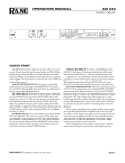
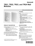
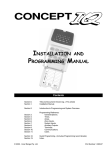
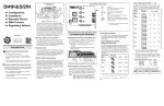
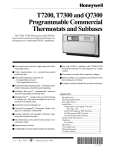
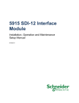
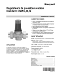
Reveal™
INSTALLATION INSTRUCTIONS
SPECIFICATIONS
Agency Approvals
• Listed device: UL/CUL
• Standards used: UL916
Physical Dimensions
• Width: 6.58 inches (147 mm)
• Height: 3.65 inches (91 mm)
• Depth: 1.42 inches (38 mm)
INTRODUCTION
Reveal™ uses Honeywell's patent pending EZ-Nav™
technology to provide real-time status information on an easyto-use, wall-mounted touch-screen LCD. Reveal has a 480 x
272, High Definition, 24-bit Full Color backlit LCD display. It is
also available in a 16-level Extended Temperature gray-scale
display. Both displays have a viewing area of 8 in2 (51.6 cm2).
Reveal has customizable user screens, multi-language
capability, and permission-based access control. With these
features it provides site personnel the ability to quickly and
conveniently access setpoint changes, local alarm data, and
other system information.
This device can be configured through the WEBs or
ComfortPoint (CP) workbench/supervisors using a software
driver.
This document contains the Installation, startup, and user
instructions for Honeywell Reveal. For further programming
instructions, go to www.Honeywell.com/manuals and
download the Reveal™ Software Installation and
Programming User Guide (form 62-0322).
LCD-CT043A100: Reveal Color Touch Screen Display
• 480 x 272 High Definition, 24-bit Full Color, Liquid Crystal
Display (LCD)
• 14°F to 122°F (-10°C to 50°C) Operating Temperature
Range
• The LCD color display is for use in a site manager's office
and/or located throughout a site for departmental
managers and facility maintenance personnel.
LCD-GT043A100: Reveal Gray-Scale Touch Screen Display
• 480 x 272 16-level Gray-Scale Display
• -4°F to 158°F (-20°C to 70°C) Operating Temperature
Range
• The LCD gray-scale display is for use inside HVAC rooftop
units, walk-in cold rooms, etc.
Operating Relative Humidity
• 5% to 95% (non-condensing)
Electrical Ratings
• Input voltage range: 20 - 30VAC, 50/60Hz, 8VA, Class 2
NOTE: Each Reveal display must have its own isolated,
non-grounded, 24 VAC power source.
Contents
Introduction ....................................................................... 1
Specifications .................................................................... 1
Ordering Information ......................................................... 2
Before Installing this Product… ........................................ 2
Mounting ........................................................................... 2
Wiring ............................................................................... 4
Power-up .......................................................................... 5
Configuration and User Access ........................................ 6
Troubleshooting ................................................................ 10
Model and Part Numbers .................................................. 10
Regulatory Compliance .................................................... 10
62-0321-01
REVEAL™
ORDERING INFORMATION
MOUNTING
When purchasing replacement and modernization products
from your TRADELINE® wholesaler or distributor, refer to the
TRADELINE® Catalog or price sheets for complete ordering
number.
NOTE: The wall plate must be mounted first so that the
wires can be pulled through the middle of the plate
before they are connected and Reveal is installed.
If you have additional questions, need further information, or
would like to comment on our products or services, please
write or phone:
1. Your local Honeywell Automation and Control Products
Sales Office (check white pages of your phone directory).
2. Honeywell Customer Care
1885 Douglas Drive North
Minneapolis, Minnesota 55422-4386
In Canada—Honeywell Limited/Honeywell Limitée, 35
Dynamic Drive, Toronto, Ontario M1V 4Z9.
International Sales and Service Offices in all principal cities of
the world. Manufacturing in Australia, Canada, Finland,
France, Germany, Japan, Mexico, Netherlands, Spain,
Taiwan, United Kingdom, U.S.A.
Reveal comes fully assembled and can easily be mounted
directly to a wall or horizontally on a standard 2 x 4 in.
electrical box.
With the optional cover plate assembly, it can be mounted
vertically on a standard 2 x 4 in. electrical box (Fig. 2 on
page 3). The mounting procedures vary depending on the
mounting location.
Mounting directly to the wall
Use Fig. 1 on page 2 and the following procedure to mount
the unit directly on the wall.
DRYWALL HOLES
APPROPRIATELY SIZED
FOR WALL ANCHORS
MOUNTING ANCHORS
(NOT SUPPLIED)
BEFORE INSTALLING THIS
PRODUCT…
CAUTION
Can cause electrical shock or equipment damage.
Disconnect power before beginning installation.
CAUTION
If this product is replacing a display that contains
mercury in a sealed tube, do not place the old
display in the trash. Contact the local waste
management authority for instructions regarding
recycling and proper disposal.
MOUNTING SCREWS (NOT SUPPLIED)
Fig. 1. Mounting the base directly to a wall.
1.
2.
IMPORTANT
This product should be installed by a trained and
experienced technician. Failure to follow these
instructions carefully could damage the product or
cause unexpected system operation.
3.
IMPORTANT
Make sure the latest software and firmware updates
have been installed by visiting www.Honeywell.com.
Register to log-in and select Software Updates
under MyHoneywell.
M28766
4.
5.
Remove the display from its wall plate (base).
Position the wall plate of the display level against the
wall and mark the wall to show the location of the two
slotted holes.
Drill two holes in the locations marked and, if necessary,
insert hollow-wall anchors.
Position the wall plate over the holes and insert and
tighten the two screws to secure the display in a level
position on the wall.
Finish wiring the wall plate before replacing the display.
See “Wiring” on page 4.
Mounting to a vertical or horizontal electrical
box
Use Fig. 2 and the following procedure to mount the display to
a standard 2 x 4 in. electrical box. The display can be
mounted to either a horizontal or vertical electrical box.
62-0321—01
2
REVEAL™
ELECTRICAL BOX
WIRE
BRACKET
#6-32 X 5/8 FLAT
HEAD SCREWS (2)
COVER PLATE
LEVEL
WIRE HOLE
LEVEL
MOUNTING HOLES (2)
WALL PLATE
WIRE HOLE
MOUNTING HOLES (2)
#6-32 X 1/4 PAN
HEAD SCREWS (2)
C
AUXE
Y
Rc
R
M
HUM
M
L
DHM
M
K
UP
M
HUM
G
Y2
DHM
NAL
ENTIO
CONV PUMP
HEAT
500
THERMOSTAT
001
23574-
M27510
Fig. 2. Mounting to a vertical electrical box using the optional Cover Plate Assembly bracket (part nbr. 50028399-001).
1.
2.
3.
4.
Remove the display from its wall plate (base).
If the 2 x 4 in. electrical box is mounted in a horizontal
orientation, position the wall plate over the box's end
holes and insert and tighten the two screws to secure
the display to the electrical box.
If the 2 x 4 in. electrical box is mounted in a vertical
orientation (Fig. 2), install an optional Cover Plate
Assembly bracket on the electrical box first and then
position the display wall plate over the bracket's
horizontal holes. Insert and tighten the two screws to
secure the display on the electrical box.
Finish wiring the wall plate before replacing the display.
See “Wiring” on page 4.
3
62-0321—01
REVEAL™
WIRING
NOTE: All communication and power connections are
intended to be wired using 18 to 22 AWG wire. Strip
approximately 1/4 in. (6.4 mm) of insulation from the
wire and connect wires to screw terminals as shown
in Fig. 3.
CAUTION
All wiring must comply with local and national
electrical codes.
NOTES:
1.
2.
3.
When attaching the unit to the wall plate, make
sure all three snap-fit latching points are fully
seated. This can be accomplished by first seating
the bottom connector of the display into the wall
plate's bottom portion and then securing the top of
the unit into the wall plate's two upper latches by
firmly pressing on the top of the display.
When removing the unit from the wall plate, lift up
on the unit from the bottom portion and pull off.
Alternatively, one can first pull the unit off from
one side of the wall plate before the other side is
unlatched.
Do NOT use any tools to pry the unit off the wall
plate.
24 VOLT TRANSFORMER
1
LCD-CT043A100
WIRING PANEL
NC
NC
NC
24 Vac
NC
PO W ER
24 Vac
NC
NC
NC
NC
C OM M
PORT
24 Vac
120 Vac
R
NC
NC
NC
C
B
SHLD
SH LD
A
A
B
WEBs/CP
CONTROLLER
RS485 COMM PORT
M28767
Fig. 3. Wiring Schematic.
Wiring 24VAC Power
When daisy chaining the displays together, connect two wires
to each screw for each of the three RS-485 communications
wires (except the last unit). No termination resistors are
required with these devices.
NOTE: Each Reveal must have its own isolated, nongrounded 24 VAC power source.
Wiring the RS-485 Network
A single Reveal display may be wired directly to a WEBs or
CP Controller as shown in Fig. 3. However, when wiring
multiple Reveal displays to the same RS-485 port on the
display network, the Reveal displays must be wired in a daisychain topology. The Reveal RS-485 network does not support
star topologies.
62-0321—01
4
Total length of network can not exceed 1,000 ft. (304.8 m) and
should use Honeywell WIR-1010 two-conductor, twisted-pair,
shielded, 22 AWG, communications cable (Belden 8761
equivalent).
NOTE: When daisy-chaining multiple Reveal units on the
same RS-485 port, remember to pull all six wires
through the wall plate.
REVEAL™
POWER-UP
4.
The device application begins the screen caching
process.
After the unit is powered-up or reset, the sequence of events
(with accompanying user screens) is as follows:
1.
At initial power up, the display remains dark for
approximately 10-12 seconds while the unit performs its
Power On Self Test sequence.
Fig. 7. Screen caching progress.
5.
The device application loads the screen object
database.
Fig. 4. Power up.
2.
Booting with progress bar shown.
ORIG ART
Fig. 8. Database load progress.
6.
The device prepares to build the screens.
Fig. 5. Booting progress.
3.
Application Started with full progress bar shown.
Fig. 9. Screen build progress.
Fig. 6. Application started progress.
5
62-0321—01
REVEAL™
7.
The default password for changing any of the Administration
or Platform settings is 9999.
The device creates and caches each screen.
NOTES:
1.
2.
The default password is only valid if the device is
in communication failure (Comm Fail).
If the device is connected (communicating to the
WEBs or CP system), then passwords are
dependent on those assigned within the WEBs or
CP Supervisor.
Fig. 10. Screen creation progress.
8.
9.
Unit power up is now complete.
The very first time a new Reveal display is powered up
(or returned to the factory default settings) the display
presents a splash screen with a Unit Configuration
button.
Fig. 12. Typical Log in screen.
Fig. 13. Typical home screen.
Fig. 11. Screen Unit Configuration button.
At this point the device is ready for configuration of the various
parameters as described in “Configuration and User Access”
on page 6.
Unit Configuration
The Unit Configuration button is where all administrative
selections, settings, and preference changes can be made.
NOTE: After a User's screen layout configuration has been
downloaded into the display, the user-defined Home
screen displays following the conclusion of all future
power-up sequences.
NOTE: Several display properties are also available for
adjustment using the Unit Configuration screen.
These properties include the ability to initiate a
download request of the user's screen layout
configuration from the WEBs or CP Controller.
CONFIGURATION AND USER ACCESS
All configuration adjustments within Platform Settings and
Administration, and all Data Items and Setpoint changes
require user authentication.
62-0321—01
6
Fig. 14. Unit Configuration screen.
REVEAL™
Platform Settings
The following can be viewed and or modified from the
Platform Settings screen (see Fig. 15):
• Contrast (only applicable to the Reveal gray-scale model)
• Brightness
•
•
•
•
•
Login Time-out
Language (Release 1.0 only supports English)
Network Address
Software Version
O.S. Version
Fig. 15. Platform screens.
Administration
•
•
•
•
•
The Administration tab on the Unit Configuration screen
allows access to the following (see Fig. 16):
• Logout
• Clean Display
• Touch Calibrate
Reboot
Upgrade Kernel
Upgrade Unit
Factory Defaults
Factory Verify
Fig. 16. Administration Screens.
7
62-0321—01
REVEAL™
Address and Screen Layout
Screens and Elements
Set Network Address
Screens and elements are fully configurable and may vary
from those shown below. They are built using a combination
of elements.
The default address of zero will not communicate with the
WEBs or CP Controller. Setting the address to any valid
address configured within the WEBs or CP Controller will
automatically establish communications with the WEBs or CP
Controller and download the user's screen layout
configuration (relevant for Reveal unit's address).
Navigation Buttons
Once the display establishes communications with the WEBs
or CP Controller, the device's user passwords will be in effect.
IMPORTANT
When installing more than one unit, make sure each
unit has a different network address.
If two units are given the same address, then the
address can not be changed from Reveal (the 9999
default password will not work). From the WEBs or
CP Controller, the network must then be disabled or
the Reveal must be put into Communication Loss
(Comm Loss) by disconnecting the network cable to
allow the 9999 password to work again.
Screen Layout Download
The initial user screen layout download begins automatically
after the Reveal's address is recognized by the display
network.
Fig. 17. Navigation Buttons.
Home Screen
The Home screen has top level buttons and associated icons
for navigation to deeper screen sets. The Home screen varies
in the types of viewable icons, depending on the users’
required access.
With Honeywell’s EZ-Nav technology, a Home icon is on every
page for quick return to the Home screen from anywhere in
the navigation.
NOTE: Downloads to multiple devices may be started and
done simultaneously.
NOTE: If a download fails, any previously loaded screen
layout is erased and the unit configuration screen
re-displays.
Refer to the Reveal™ Software Installation and Programming
User Guide (form 62-0322) for full software installation,
update, and programming details.
Fig. 18. Home screen.
Navigation List Screen
The Navigation List screen shows the various zones and
floors with optional summary data values on the buttons.
Fig. 19. Navigation List screen.
62-0321—01
8
REVEAL™
Data List Screen
The Data List screen contains all data available for each zone
or floor selected. This screen also includes a list of data
buttons with optional summary data values and read-only
(gray text) or editable points (green text).
NOTE: For gray-scale Reveal displays, the read-only points
are displayed with a lighter shade of gray.
Fig. 21. Data Editing screen.
Override Screen
The Override screen, which may or may not be used, contains
the following features:
• Buttons directly modify enumeration points when pressed
• Access code not required to modify
Fig. 20. Data List screen.
Alarm List Screen
Data Editing Screen
The Data Editing screen can be accessed directly by selecting
the editable points on the Data List screen. This page allows
editing data values via the EZ-Nav up and down arrows for
simplified usability.
The Alarm List screen, which may or may not be used,
contains the following features:
• List of current alarms
• Shows source and time of alarm occurrence
Alarm Details Screen
The Alarm Details screen, which may or may not be used,
contains the following features:
• Source point and present value
• Time of occurrence plus number of occurrences
• Acknowledge state and time
• Messages and notes
9
62-0321—01
REVEAL™
TROUBLESHOOTING
REGULATORY COMPLIANCE
Following the successful installation (mounting, wiring, unit
configuration) and screen layout download of Reveal from a
properly configured and active WEBs or CP Controller, a user
Home screen similar to the one shown below should be visible
on the Reveal display.
Meets AS/NZS CISPR 11- Mark for Australian and New
Zealand C-Tick.
Federal Communications Commission (FCC)
This equipment has been tested and found to comply with the
limits for a Class A digital device, pursuant to Part 15 Subpart
B of the FCC Rules. These limits are designed to provide
reasonable protection against such interference when
operated in a commercial environment. Operation of this
equipment in a residential area may cause interference, in
which case, users at their own expense will be required to
take whatever measures may be required to correct the
interference. Any unauthorized modification of this equipment
may result in the revocation of the owner's authority to
continue its operation.
Canadian Department of Communication (DOC)
NOTE: This Class A digital apparatus meets all
requirements of the Canadian Interference-Causing
Equipment Regulations.
Fig. 22. Typical home screen.
If the viewable screen is not similar to the one shown above,
the following troubleshooting tips may help to determine the
cause of the problem:
1. Check that the WEBs or CP Controller is powered up
and that the Reveal driver and all uploads have been
completed.
2. Check that the Reveal driver is not reporting any
communication faults with the device. If the installation
is on a site with multiple Reveal displays, faults could be
caused by a duplicate network address on the Reveal
displays.
3. For technical support, please call 1-800-328-2231 or
send an e-mail to to [email protected].
MODEL AND PART NUMBERS
Table 1 provides the part numbers that should be used to
order the necessary Honeywell parts.
Table 1. Part Numbers.
Product
Reveal Color Display
Part Number.
LCD-CT043A100
Reveal Gray-Scale Display
LCD-GT043A100
Cover Plate Assembly
50028399-001
WIR-1010 Two-conductor shielded
communications cable
(Belden 8761 equivalent)
709001000
62-0321—01
10
Cet appareil numerique de la Classe A respecte
toutes les exigencies du Reglement sur le material
broilleur du Canada.
CE Declaration of Conformity
Honeywell declares under its sole responsibility that the
Reveal is in conformity with EMC Standard EN61326.
NOTE: To maintain international compliance, the Reveal
must be powered by a CE-certified, UL Class 2
transformer.
Waste Electrical & Electronic Equipment
Customers are advised to dispose of this product at the end of
its useful life according to applicable local laws, regulations,
and procedures.
REVEAL™
11
62-0321—01
REVEAL™
Reveal™ and EZ-Nav™ are trademarks of Honeywell International Inc.
Automation and Control Solutions
Honeywell International Inc.
1985 Douglas Drive North
Golden Valley, MN 55422
Honeywell Limited-Honeywell Limitée
35 Dynamic Drive
Toronto, Ontario M1V 4Z9
customer.honeywell.com
® U.S. Registered Trademark
© 2009 Honeywell International Inc.
62-0321—01 M.S. 10-09
Printed in U.S.A.