1
Quick Start Guide
Cisco 1760 Modular Access Router Cabling and Installation
INCLUDING LICENSE AND WARRANTY
1
Cisco One-Year Limited Hardware Warranty Terms
2
Overview
3
Parts List
4
Mounting the Router in a Rack
5
Installing WIC/VIC Cards
6
Connecting the Router to Your Local Network
7
Connect Power and Verify Installation
8
Connect a PC to the Router Console Port
9
Perform Initial Configuration
10 Use the CLI to Configure VoIP
11 Obtaining Documentation
12 Documentation Feedback
13 Cisco Product Security Overview
14 Obtaining Technical Assistance
15 Obtaining Additional Publications and Information
1 Cisco One-Year Limited Hardware Warranty Terms
There are special terms applicable to your hardware warranty and various services that you can use during the warranty period.
Your formal Warranty Statement, including the warranties and license agreements applicable to Cisco software, is available on
Cisco.com. Follow these steps to access and download the Cisco Information Packet and your warranty and license agreements
from Cisco.com.
1. Launch your browser, and go to this URL:
http://www.cisco.com/univercd/cc/td/doc/es_inpck/cetrans.htm
The Warranties and License Agreements page appears.
2. To read the Cisco Information Packet, follow these steps:
a. Click the Information Packet Number field, and make sure that the part number 78-5235-03A0 is highlighted.
b. Select the language in which you would like to read the document.
c. Click Go.
The Cisco Limited Warranty and Software License page from the Information Packet appears.
d. Read the document online, or click the PDF icon to download and print the document in Adobe Portable Document
Format (PDF).
Note
You must have Adobe Acrobat Reader to view and print PDF files. You can download the reader from Adobe’s
website: http://www.adobe.com
3. To read translated and localized warranty information about your product, follow these steps:
a. Enter this part number in the Warranty Document Number field:
78-10747-01C0
b. Select the language in which you would like to view the document.
c. Click Go.
The Cisco warranty page appears.
d. Read the document online, or click the PDF icon to download and print the document in Adobe Portable Document
Format (PDF).
You can also contact the Cisco service and support website for assistance:
http://www.cisco.com/public/Support_root.shtml.
Duration of Hardware Warranty
One (1) Year
Replacement, Repair, or Refund Policy for Hardware
Cisco or its service center will use commercially reasonable efforts to ship a replacement part within ten (10) working days after
receipt of a Return Materials Authorization (RMA) request. Actual delivery times can vary, depending on the customer location.
Cisco reserves the right to refund the purchase price as its exclusive warranty remedy.
To Receive a Return Materials Authorization (RMA) Number
Contact the company from whom you purchased the product. If you purchased the product directly from Cisco, contact your Cisco
Sales and Service Representative.
2
Complete the information below, and keep it for reference.
Company product purchased from
Company telephone number
Product model number
Product serial number
Maintenance contract number
2 Overview
This document describes the hardware installation and software configuration steps necessary to install your Cisco 1760
modular access router with its complement of WAN interface cards (WICs) and voice interface cards (VICs). Additional
documentation can be found on Cisco.com.
Product Serial Number Location
The serial number label for Cisco 1760 router is located on the rear of the chassis, in the lower right-hand corner.
3 Parts List
Your router package should include the following items:
• One Cisco 1760 modular access router
• One blue RJ-45-to-DB-9 console cable
• One DB-25-to-DB-9 adapter
• One black power supply cord
• Cable guide
• Rack-mounting brackets
• Product documentation
4 Mounting the Router in a Rack
Warning
To prevent bodily injury when mounting or servicing this unit in a rack, you must take special precautions to ensure
that the system remains stable. The following guidelines are provided to ensure your safety.
• This unit should be mounted at the bottom of the rack if it is the only unit in the rack.
• When mounting this unit in a partially filled rack, load the rack from the bottom to the top with the heaviest component
at the bottom of the rack.
• If the rack is provided with stabilizing devices, install the stabilizers before mounting or servicing the unit in the rack.
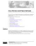
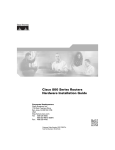
The rack-mounting brackets supplied with the router can be attached to a 19- or 24-inch rack. Figure 1 shows the bracket
mounting points that attach to the rack.
3
Figure 1
Bracket Mounting Points
24" rack
mount point
19" rack
mount point
24" rack
mount point
38398
19" rack
mount point
To install the router in a 19-inch or a 24-inch standard rack, follow the instructions described in these procedures:
• Attaching Brackets to the Router
• Attaching Brackets to the Rack
• Attaching the Optional Cable Guide
Attaching Brackets to the Router
The bracket orientation and the screws you use depend on whether you are attaching the brackets for a 19-inch or a 24-inch
rack. Use two of the supplied screws to attach each bracket, according to the following guidelines:
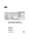
• For a 19-inch rack, use the supplied number-8 Phillips flat-head screws to attach the long side of the bracket to the router.
• For a 24-inch rack, use the supplied number-8 Phillips truss-head screws to attach the short side of the bracket to the router.
Figure 2 shows how to attach brackets to the two sides of the router with the front panel forward.
Attaching Brackets for 19- and 24-Inch Racks
PWR
OK
PVDM 0
PVDM 1
MOD
OK
OK
OK
19" Configuration
Phillips
flat-head
screws
4
SLOT 0
OK
0
1
SLOT 1
OK
0
1
60942
Figure 2
OK
PVDM 0
PVDM 1
MOD
OK
OK
OK
SLOT 0
OK
24" Configuration
0
1
SLOT 1
OK
0
1
60943
PWR
Phillips
truss-head
screws
Attaching Brackets to the Rack
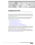
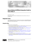
After the brackets are attached to the router, use the four supplied number-12 Phillips machine screws to securely attach the
brackets to the rack, as shown in Figure 3.
Caution
Make sure that the fans on the side of the chassis are not blocked.
Figure 3
Attaching Brackets to the Rack
CONSOLE
OK
PVDM 0
PVDM 1
MOD
OK
OK
OK
SLOT 0
OK
0
1
SLOT 1
OK
0
1
ACT
COL
FDX
100
LINK
10/100 ETHER
Cisco 170
NET
AUX
SLOT 2
OK
0
1
SLOT 3
OK
0
1
0 Series
60941
PWR
Phillips machine screws
Attaching the Optional Cable Guide
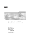
Cisco recommends attaching the cable guide to prevent the cables from obscuring the front panel of the router and the other
devices installed in the rack. If the router is in a 19-inch or 24-inch rack, use the supplied black screw, as shown in Figure 4, to
attach the cable guide to the left or right bracket.
5
Figure 4
Attaching the Cable Guide to the Router
CONSO
LE
OK
PVDM 0
PVDM 1
MOD
OK
OK
OK
SLOT 0
OK
0
1
SLOT 1
OK
0
1
ACT
COL
FDX
100
LINK
Cisco 170
10/100 ETHER
NET
AUX
SLOT 2
OK
0
1
SLOT 3
OK
0
1
0 Series
65286
PWR
Cable guide screw
5 Installing WIC/VIC Cards
The router has four card slots that hold Cisco WICs and VICs. Either one or two WICs may be installed, with the remaining
slots holding VICs, as desired. If no WICs are present in the slots, up to four VICs may be installed. Each WIC has one or two
WAN ports, and each VIC has two or more voice ports. This section describes the procedure for installing a WIC or a VIC in
the router.
Note
For details on specific WICs and VICs, on how to connect a WIC to the WAN line or a VIC to the telephone and fax
line, and on how to configure the interface with Cisco IOS software, refer to the Cisco WAN Interface Cards Hardware
Installation Guide that came with the cards.
Safety Information
This section lists safety warnings that you should be aware of before installing WICs or VICs in the router. To see translated
versions of these warnings, refer to the Regulatory Compliance and Safety Information for the Cisco 1700 Routers document
that came with the router.
Warning
Before working on a system that has an on/off switch, turn off the power and unplug the power cord.
Warning
Only trained and qualified personnel should be allowed to install or replace this equipment.
Warning
Before working on equipment that is connected to power lines, remove jewelry (including rings, necklaces, and
watches). Metal objects will heat up when connected to power and ground and can cause serious burns or weld
the metal object to the terminals.
Warning
Before opening the chassis, disconnect the telephone-network cables (from the card) to avoid contact with the
telephone-network voltages.
Warning
Do not work on the system or connect or disconnect cables during periods of lightning activity.
6
Do not connect a WAN, telephone or fax cable to the card until you have completed the installation procedure.
Caution
Card Installation
Follow these steps to insert a card in the router:
Make sure the router is turned off and is disconnected from AC power.
Step 1
Power must be removed from the system prior to installing or removing WICs or VICs to avoid damaging them.
When WICs or VICs are pushed into or pulled out of a router that is powered up, there is a very good chance that
they could be damaged electrically and will no longer function.
Caution
Loosen the thumbscrews on the WIC or VIC slot cover, as shown in Figure 5.
Figure 5
Removing a WIC or VIC Slot Cover
60950
Step 2
CONSOLE
PWR
OK
PVDM 0
PVDM 1
MOD
OK
OK
OK
SLOT 0
OK
0
1
SLOT 1
OK
0
1
ACT
COL
FDX
100
LINK
Cisco 170
10/100 ETHE
RNET
0 Series
AUX
SLOT 2
OK
0
1
SLOT 3
OK
0
1
You should be able to loosen the screws using your fingers; however, if the screws are very tight, you may need to use a Phillips
screwdriver.
Step 3
Remove the metal plate that covers the card slot.
Step 4
Hold the card by the edges on either side of the card front panel, and line up the card edges with the guides inside the
card slot, as shown in Figure 6.
Figure 6
Inserting a WIC or VIC in the Router
2
60949
1
CONSOLE
PWR
OK
PVDM 0
PVDM 1
MOD
OK
OK
OK
SLOT 0
OK
0
1
SLOT 1
OK
0
1
ACT
COL
FDX
100
LINK
Cisco 170
10/100 ETHE
RNET
0 Series
AUX
SLOT 2
OK
0
1
SLOT 3
OK
0
1
1
Interface Card
Step 5
Insert the card in the slot, and gently push it into the router until the front panel of the card is flush with the router.
2
Guides
7
Slots 2 and 3 accept VICs only. These slots have a small metal tab on the right side that interferes with a similar
tab on WICs, preventing the insertion of WICs by mistake.
Note
Step 6
Tighten the screws that are on the card.
Voice Port Verification
When the router is connected to a PC and you are running the command-line interface, as described in the “Connect a PC to
the Router Console Port” section, you can enter the show voice port command to identify the port numbers of voice interfaces
installed in your router:
Router# show voice port slot-number/port-number
As an example of voice port numbering, if you install VICs in both slot 1 and slot 2 of the router, the ports in each of these slots
would be numbered as follows:
Slot 1—1/0 and 1/1
Slot 2—2/0 and 2/1
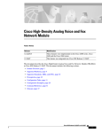
Figure 7 shows the Cisco 1760 router front panel and slot numbering.
Figure 7
Cisco 1760 Router Front Panel
1
2
3
CONSOLE
OK
PVDM 0 PVDM 1
OK
OK
MOD
OK
SLOT 0
OK
0
1
SLOT 1
OK
0
1
ACT
COL
FDX
100
LINK
10/100 ETHERNET
AUX
9
8
5
THESE SLOTS ACCEPT ONLY VOICE INTERFACE CARDS
SLOT 2
OK
0
1
SLOT 3
OK
0
Cisco 1700
Series
1
60906
PWR
4
16 15
14
13 12
11
10
7
6
1
WIC/VIC Slot 0
9
Ethernet Port
2
WIC/VIC Slot 1
10
Ethernet LEDs
3
Console Port
11
Slot 1 LEDs
4
VIC Slot 2
12
Slot 0 LEDs
5
VIC Slot 3
13
MOD OK LED
6
Slot 3 LEDs
14
PVDM 0/1 OK LEDs
7
Slot 2 LEDs
15
Router OK LED
8
Auxiliary Port
16
Power LED
6 Connecting the Router to Your Local Network
The router is connected to your local Ethernet network through the yellow 10/100 Ethernet port. You must provide the
following items for this connection:
• A straight-through, RJ-45-to-RJ-45 Ethernet cable
• A 10/100-Mbps Ethernet hub or switch
8
Warning
The ports labeled 10/100-Mbps Ethernet port and Console port are safety extra-low voltage (SELV) circuits. SELV
circuits should only be connected to other SELV circuits. Because BRI circuits are treated like telephone-network
voltage, avoid connecting the SELV circuits to the telephone network voltage (TNV) circuits. (To see translated
versions of this warning, refer to the Regulatory Compliance and Safety Information for Cisco 1700 Routers
document that came with the router.)
Caution
Always connect the Ethernet cable to the yellow ports on the router. Do not connect the cable to an ISDN S/T or
U port on a WIC or to an NT1 that is connected to a WIC. Accidentally connecting the cable to the wrong port can
damage your router.
Follow these steps to connect the router to your local network:
Connect one end of the Ethernet cable to the yellow Ethernet port (labeled 10/100-Mbps Ethernet port), as shown in
Figure 8.
Step 1
Figure 8
Connecting the Router to the Local Network
CONSO
LE
PWR
OK
PVDM 0
OK
PVDM 1
OK
MOD
OK
SLOT 0
OK
0
1
SLOT 1
OK
0
1
ACT
COL
FDX
100
LINK
Cisco 170
10/100 ETHER
NET
0 Series
AUX
SLOT 2
OK
0
1
SLOT 3
OK
0
1
1
2
1X 2X
ETHERNE
T 3X
4X
1 2 3
4
5 6 7
8
5X
3
6X
7X
8X
60945
SPEED
LED
100BaseT
X SOLID
10BaseT
BLINK
MDI
MDI-X
1
10/100 Ethernet port
2
Ethernet hub or switch
Step 2
Connect the other end of the Ethernet cable to a network port on the hub or switch.
3
Straight-through Ethernet cable
7 Connect Power and Verify Installation
Read the following warnings before connecting the power to the router.
Warning
The power supply is designed to work with TN power systems.
9
Warning
This product relies on the building’s installation for short-circuit (overcurrent) protection. Ensure that a fuse or
circuit breaker no larger than 120VAC, 15A U.S. (240VAC, 16A international) is used on the phase conductors (all
current-carrying conductors).
Warning
This equipment needs to be grounded. Use a green-and-yellow 14 AWG ground wire to connect the host to earth
ground during normal use.
Warning
When installing the unit, always make the ground connection first and disconnect it last.
Warning
Never defeat the ground conductor or operate the equipment in the absence of a suitably installed ground
conductor. Contact the appropriate electrical inspection authority or an electrician if you are uncertain that
suitable grounding is available.
Follow these steps to connect power to the router and to turn the router on:
Step 1
Figure 9
Connect the separate power cord to the power socket on the rear panel, as shown in Figure 9.
Connecting the Power Supply
60948
100-240
V~
1.5 MAX
/1.5A MAX
50-60
Hz
Step 2
Connect the other end of the separate power cord to a power outlet.
Step 3
Turn the power switch to on ( | ).
Step 4
Verify that you have correctly installed the router by checking the following LEDs:
• PWR—On when power is being supplied to the router.
• LINK—On when the router is correctly connected to the local Ethernet LAN through the 10/100-Mbps Ethernet
port.
• ETH ACT—Blinking when there is network traffic on the local Ethernet LAN.
• SLOT OK—On when a WIC is correctly installed in the slot.
• PVDM 0/1 OK—On when a packet voice data module (PVDM) is correctly installed in its slot and is recognized
by the system.
10
• MOD OK—On when the virtual private network (VPN) module is correctly installed in its slot and is recognized
by the system.
8 Connect a PC to the Router Console Port
Connect a PC to the router’s console port and establish a console session to view startup messages and verify voice card
installation. Follow these steps to connect the router to a terminal or PC:
Connect the light blue console cable to the blue console port on the router, as shown in Figure 10.
Step 1
Figure 10
Connecting the Console Cable to the Router
CONSO
LE
PWR
OK
PVDM 0
OK
PVDM 1
OK
MOD
OK
SLOT 0
OK
0
1
SLOT 1
OK
0
1
ACT
COL
FDX
100
LINK
Cisco 170
10/100 ETHER
NET
0 Series
AUX
SLOT 2
OK
0
1
SLOT 3
OK
0
1
3
60946
1
2
1
Blue console port
2
To PC or terminal
Step 2
Use the console adapter to connect the other end of the cable to the terminal or PC. If your terminal or PC has a console
port that does not fit the adapter included with the router, you must provide the correct adapter for that port.
Step 3
Start HyperTerminal or a similar terminal emulation program on your PC. Select the appropriate PC COM port. Set
the configurations to 9600 baud, 8 data bits, 1 stop bit, no flow control, and no parity.
3
Light blue console cable
Startup messages begin to appear in your terminal emulation program window.
Caution
Do not press any keys on the keyboard until the messages stop. Any keys pressed during this time are interpreted
as the first command typed when the messages stop, which might cause the router to power off and start over. It
will take a few minutes for the messages to stop.
– If you see the following messages, the router has booted with a configuration file and is ready for initial configuration
using the Cisco Router and Security Device Manager (SDM):
yourname con0 is now available
Press RETURN to get started.
See the “Initial Configuration Using Cisco Router and Security Device Manager” section on page 12 to learn how to
configure your router using SDM or to learn how to obtain SDM and install it on your router.
– If you see the following messages, the router has booted and is ready for initial configuration using the setup command
facility or the command-line interface (CLI):
11
--- System Configuration Dialog --At any point you may enter a question mark '?' for help.
Use ctrl-c to abort configuration dialog at any prompt.
Default settings are in square brackets '[]'.
Would you like to enter the initial configuration dialog? [yes/no]:
To learn how to use the CLI to configure the router, see the “Initial Configuration Using Cisco CLI—Manual
Configuration” section on page 12.
9 Perform Initial Configuration
You can configure your router by using one of the following tools:
• Security Device Manager—If your router was purchased with a VPN bundle, Security Device Manager is installed on the
router. See “Initial Configuration Using Cisco Router and Security Device Manager” to determine if SDM is installed on
the router. For instructions on configuring your router by using SDM, refer to the Cisco Security Device Manager (SDM)
Quick Start Guide that shipped with your router. Voice over IP configuration must be done using the CLI, but you can use
SDM to configure LAN and WAN connections, firewalls, VPNs, routing and other features.
• Command-line interface (CLI)—If you prefer to use the Cisco IOS CLI, see the “Initial Configuration Using Cisco
CLI—Manual Configuration” section on page 12 for instructions on how to use the CLI.
Initial Configuration Using Cisco Router and Security Device Manager
If the following messages appear at the end of the startup sequence, Cisco Router and Security Device Manager (SDM) is
installed on your router:
yourname con0 is now available
Press RETURN to get started.
For instructions on configuring your router by using SDM, refer to the Cisco Router and Security Device Manager (SDM) Quick
Start Guide that shipped with your router.
Tip
If the messages above do not appear, SDM and the Cisco Router and Security Device Manager (SDM) Quick Start
Guide were not shipped with your router. If you want to use SDM, you can download the latest version of SDM and
instructions for installing it on your router from the following location:
http://www.cisco.com/pcgi-bin/tablebuild.pl/sdm
To obtain the SDM quick start guide, SDM release notes, and other SDM documentation, go to www.cisco.com/go/sdm
and click the Technical Documentation link.
Initial Configuration Using Cisco CLI—Manual Configuration
This section shows how to display a command-line interface (CLI) prompt for configuration using the CLI, and it directs you to
documentation for the CLI configuration.
You can use the CLI if the following messages appear at the end of the startup sequence:
--- System Configuration Dialog --At any point you may enter a question mark '?' for help.
Use ctrl-c to abort configuration dialog at any prompt.
Default settings are in square brackets '[]'.
Would you like to enter the initial configuration dialog? [yes/no]:
12
If these messages do not appear, SDM and a default configuration file were installed on the router at the factory. To use SDM
to configure the router, see the “Initial Configuration Using Cisco Router and Security Device Manager” section on page 12.
Note
Be sure to save your configuration changes occasionally so that they are not lost during resets, power cycles, or power
outages. Use the copy running-config startup-config command at the privileged EXEC mode prompt (Router#) to save
the configuration to NVRAM.
Step 1
To proceed with manual configuration using the CLI, enter no when the power-up messages end.
Would you like to enter the initial configuration dialog? [yes/no]: no
Step 2
Press Return to terminate autoinstall and continue with manual configuration.
Would you like to terminate autoinstall? [yes] Return
Several messages appear, ending with a line similar to the following:
Copyright (c) 1986-2000 by cisco Systems, Inc.
Compiled <date> <time> by <person>
Step 3
Press Return to display the Router> prompt.
...
flashfs[4]: Initialization complete.
Router>
Step 4
Enter privileged EXEC mode.
Router> enable
Router#
Step 5
For configuration using the CLI, refer to the applicable configuration procedures in the Cisco 1700 Router Software
Configuration Guide documentation at the following URL:
http://www.cisco.com/univercd/cc/td/doc/product/access/acs_mod/1800/sw/index.htm
Step 6
Verify the initial configuration. See the “Verifying the Initial Configuration” section on page 13 for verification
procedures.
Verifying the Initial Configuration
To verify that the new interfaces are operating correctly, perform the following tests:
• To verify that the interfaces are operating correctly and that the interfaces and line protocol are in the correct state—up or
down—enter the show interfaces command.
• To display a summary status of the interfaces configured for IP, enter the show ip interface brief command.
• To verify that you configured the correct host name and password, enter the show configuration command.
• To identify the port numbers of voice interfaces installed in your router enter the show voice port command:
Router# show voice port slot-number/port-number
As an example of voice port numbering, if you installed VICs in both slot 1 and slot 2 of the router, the ports in each of
these slots would be numbered as follows:
Slot 1—1/0 and 1/1
Slot 2—2/0 and 2/1
When you have completed and verified the initial configuration, your Cisco router is ready to configure for specific functions.
Configuring the Router Using the Cisco IOS CLI
13
10 Use the CLI to Configure VoIP
The following sections explain how to set up basic VoIP configurations using the Cisco IOS command line interface (CLI).
Note
VoIP requires one of the IP/Plus/Voice feature sets from IOS Release 12.2(2)XK, or later.
• Information for International Users
• Saving the Configuration
• Configuring the Fast Ethernet Interface
• Configuring a Dial Plan
• Configuring Voice Interface Cards
• Configuring Quality of Service
• IP Precedence
• Low Latency Queuing
• Multilink PPP with Link Fragmentation Interleave
• Real-Time Transport Protocol Header Compression
• Frame Relay Configuration for VoIP
Information for International Users
International users must set the values of certain voice-port commands, such as cptone, that are specific to their country. Refer
to the Cisco 1751 Router Software Configuration Guide, available on Cisco.com, for details.
The rest of this guide explains how to configure your router for VoIP traffic.
Saving the Configuration
You must save the new configuration to nonvolatile RAM (NVRAM) periodically during the configuration process and also
when you finish configuring the router.
Cisco IOS software uses two configuration files—startup-config and running-config. The startup-config file is a backup file that
has all the information you specified about the router interfaces. The startup-config file is used by the router on the next restart.
The running-config file has the current operating configuration with the changes you have just made. You can make any changes
to the running-config file; however, these changes will be lost when the router powers down. To make these changes permanent,
copy the running-config file to the startup-config file stored in NVRAM.
Follow these steps for each router to write the new configuration to NVRAM:
Step 1
Step 2
Exit configuration mode, and return to the enable prompt by pressing Ctrl-Z or entering the end global configuration
command.
To see the startup configuration stored in NVRAM, enter the following command:
Router# show startup-config
Step 3
To see the operating configuration, including any changes you have just made, enter the following command:
Router# show running-config
Step 4
To write your changes to NVRAM and make them permanent, enter the following command:
Router# copy running-config startup-config
Building configuration. . .
[OK]
Router#
14
The router is now configured to start in the new configuration.
Configuring the Fast Ethernet Interface
To configure the Fast Ethernet interface, follow these steps, beginning in global configuration mode:
Command
Purpose
Step 1
Router(config)# interface
fastethernet 0/0
Enter configuration mode for the Fast Ethernet interface.
Step 2
Router(config-if)# ip address
20.20.20.20 255.255.255.0
Set the IP address and subnet mask for the Fast Ethernet
interface.
Step 3
Router(config-if)# no shutdown
Enable the Fast Ethernet interface.
Step 4
Router(config-if)# exit
Exit configuration mode for the Fast Ethernet interface.
Configuring a Dial Plan
Use a dial plan to map the destination telephone numbers with the voice ports on the router. In North America, the North
American Numbering Plan (NANP) is used, which consists of an area code, an office code, and a station code. Area codes are
assigned geographically, office codes are assigned to specific switches, and station codes identify specific ports on each switch.
The format in North America is 1Nxx-Nxx-xxxx, with N = digits 2 through 9 and x = digits 0 through 9. Internationally, each
country is assigned a one- to three-digit country code; the country’s dialing plan follows the country code.
In corporate environments, VoIP can be configured to recognize extension numbers and expand them into their full E.164
(international public telecommunications numbering plan) dialed numbers by using two commands in tandem:
destination-pattern and num-exp. Before you configure these two commands, map individual telephone extensions with their
full E.164 dialed numbers. You can do this easily by creating a number expansion table.
For Cisco voice implementations, three types of dial peers are used to match a dialed number to either a local telephony port or
a remote IP address:
• A POTS dial peer associates a physical voice port with a local telephone device. The key commands that you need to
configure are the port and destination-pattern commands, as in the following example:
Router(config)# dial-peer voice 401 pots
Router(config-dial-peer)# destination-pattern 14085553737
Router(config-dial-peer)# port 0/0
The destination-pattern command defines the telephone number associated with the POTS dial peer. The port command
associates the POTS dial peer with a specific logical dial interface, normally the voice port connecting your router to the
local POTS network.
• A VoIP dial peer associates a telephone number with an IP address. The key commands that you need to configure are the
destination-pattern and session target commands, as in the following example:
Router(config)# dial-peer voice 501 voip
Router(config-dial-peer)# destination-pattern 1919555....
Router(config-dial-peer)# session target ipv4:192.168.11.3
The destination-pattern command defines the telephone number associated with the VoIP dial peer. The session target
command specifies a destination IP address for the VoIP dial peer.
• A Voice over Frame Relay (VoFR) dial peer associates a telephone number with a Frame Relay data-link connection
identifier (DLCI). The key commands you need to configure are the destination-pattern and session target commands, as in
the following example:
Router(config)# dial-peer voice 601 vofr
Router(config-dial-peer)# destination-pattern 14087677448
Router(config-dial-peer)# session target serial 0/0 100
15
The destination-pattern command defines the telephone number associated with the VoFR dial peer. The session target
command specifies a destination DLCI for the VoFR dial peer.
Use the dial-peer voice command to define dial peers and to change to dial peer configuration mode. For examples, see the
“Configuring FXS Interfaces” section on page 17, the “Configuring FXO Interfaces” section on page 23, and the “Configuring
E&M Interfaces” section on page 24.
Wildcards and Number Expansion
Office PBXs are configured so that a user can dial a local call (within the same PBX) by dialing the extension only—for instance,
the four-digit extension 3737, or the five-digit extension 53737—rather than dialing the full telephone number, 1 408 555-3737.
You can provide the same shortcut on a VoIP network by using the number-expansion (num-exp) command.
Router(config)# num-exp 5.... 1408555....
This command tells the router to expand a particular sequence of dialed numbers into a complete telephone number (destination
pattern) as shown in Table 1.
Table 1
Sample Number Expansion Table
Extension
Destination
Pattern
3737
Num-Exp Command Entry
Description
14085553737
num-exp 3737
14085553737
To expand 3737 to
14085553737
....
1408555....
num-exp .... 1408555....
To expand any dialed sequence
of four digits (represented by
four periods) by prefixing
1408555 to it
5....
1408555....
num-exp 5.... 1408555....
To expand a five-digit extension
beginning with the numeral 5 by
prefixing 140855 to it
You can use a period (.) as a wildcard character representing a single digit in a telephone number.
You can use the show num-exp command to verify the number expansion information.
Router# show num-exp [dialed-number]
After you have configured dial peers and assigned destination patterns to them, you can use the show dialplan number command
to see how a telephone number maps to a dial peer.
Router# show dialplan number [dialed-number]
Note
You must still configure each telephone number in full on a local dial peer so that the router can find the voice port to
which it belongs.
Configuring Voice Interface Cards
The router supports one to four Cisco VICs. Each VIC provides two ports. You need one VIC port for each voice connection.
Note
To transmit voice calls over an IP WAN, you need (in addition to the VICs) at least one WIC in the router to provide
the connection to the WAN.
There are five types of VIC interfaces:
• An FXS (foreign exchange station) interface connects directly to a standard telephone, a fax machine, or a similar device.
The FXS VIC interface supplies ringing voltage, dial tone, and similar signals to the station. Ports on this VIC are gray.
16
• An FXO (foreign exchange office) interface connects local calls to a PSTN central office or to a PBX that does not support
E&M signaling. This is the interface a standard telephone provides. Ports on this VIC are pink.
• An E&M is a signaling technique for two-wire and four-wire telephone and trunk interfaces. The E&M VIC connects
remote calls from an IP network to a PBX for local distribution. Ports on this VIC are brown.
• A DID is a service offered by telephone companies that allows external callers to dial an internal extension directly, without
operator assistance. The VIC connects remote calls from the PSTN to a PBX for local distribution.
• The ISDN BRI NT/TE VIC provides a client-side (terminal equipment, or TE) ISDN S/T physical interface for connection
to an NT1 device terminating an ISDN telephone network. It can also be configured to provide a network termination (NT)
interface with phantom power. Each of its two ports can carry two voice calls (one over each ISDN B channel), for a total
of four calls per ISDN BRI card. At present, the ISDN BRI VIC does not support ISDN devices such as digital telephone,
fax, or modem.
Figure 11 shows a typical VIC.
Voice Interface Card
VIC
E&M
IN USE
VIC port 0
IN USE
VIC port 1
1
SEE MANUAL BEFORE INSTALLATION
10694
Figure 11
0
You should install and cable the VICs before you perform the software configuration tasks that follow.
Configuring FXS Interfaces
This section explains how to configure ports on FXS VICs that connect directly to a standard telephone, a fax machine, or a
similar device.
Figure 12 shows a basic voice network. A small business uses a Cisco 1760 router (named West) to provide telephone and fax
connections among employees in its office. Two of these telephones are connected to an FXS VIC port in the West router.
Figure 12
Basic Voice Network (West Router)
408 555-3737
FXS VIC
0/0
West
FXS VIC
0/1
22634
408 555-4141
IP cloud
Note
You can name your router by using the global configuration hostname command.
(For information about port numbering, see the “Voice Port Verification” section.)
17
Table 2
West Router Telephone Numbers and Voice Ports
Telephone Number
Voice Port
408 555-3737
0/0
408 555-4141
0/1
Note
If your router is configured with four 2-port VICs, you can connect a total of eight telephones and fax machines to it.
As the router has only four slots, you need to replace one VIC with a WIC to provide an interface for IP connectivity
to the WAN and for data traffic. To accommodate more voice devices, you need to add more routers or use an E&M
VIC and a local PBX, rather than connecting every telephone to its own FXS VIC.
Local Dial Peers
To route a received voice call to the right destination, the router needs to know which telephone number belongs to each voice
port. For instance, if a call comes in for 408 555-3737, the router needs to know that this telephone is connected to voice port
0/0 (as shown in Figure 12). In other words, the router needs to know the information in Table 2.
To hold this information, Cisco IOS software uses objects called dial peers. A telephone number, a voice port, and other call
parameters are tied together by associating them all with the same dial peer. Configuring dial peers is similar to configuring
static IP routes—you are telling the router what path to follow to route the call. All voice technologies use dial peers to define
the characteristics associated with a call leg. A call leg is a segment of a call path, for instance, between a telephone and a router,
a router and a network, a router and a PBX, or a router and the PSTN. Each call leg corresponds to a dial peer.
Dial peers are identified by numbers, but they are usually referred to as tags to avoid confusion with telephone numbers.
Dial-peer tags are arbitrary integers that can range from 1 to 231 – 1 (2147483647). Within the allowed range, you can choose
any dial-peer tag that is convenient or that makes sense to you. Dial peers on the same router must have unique tags, but you
can reuse the tags on other routers.
Table 3 assigns a dial-peer tag to each telephone number and its associated voice port on the West router. This type of dial peer
is called a POTS dial peer or a local dial peer. The term POTS (plain old telephone service) means that the dial peer associates
a physical voice port with a local telephone device. (Voice over IP, or VoIP, dial peers are explained in the “Calling Between
Routers” section on page 20.)
Table 3
West Router Local Dial Peers
Telephone Number
Voice Port
Dial-Peer Tag
408 555-3737
0/0
401
408 555-4141
0/1
402
You should construct a table similar to Table 3 for your own routers, assigning your own telephone numbers and dial-peer tags.
Note
The telephone numbers used in this guide are only examples and are invalid for public use in the United States. When
you configure your network, be sure to substitute your own telephone numbers.
To configure the router with the dial-peer information in Table 3, enter the following global configuration commands:
West> enable
Password:
West# configure terminal
West(config)# dial-peer voice 401 pots
West(config-dial-peer)# destination-pattern 14085553737
West(config-dial-peer)# port 0/0
West(config)# dial-peer voice 402 pots
West(config-dial-peer)# destination-pattern 14085554141
West(config-dial-peer)# port 0/1
West(config-dial-peer)# exit
18
West(config)#
These commands are summarized in Figure 13.
Figure 13
West Router Configured for Local Dial Peers
dial-peer voice 401 pots
destination-pattern 14085553737
port 0/0
FXS VIC
0/0
FXS VIC
0/1
dial-peer voice 402 pots
destination-pattern 14085554141
port 0/1
22635
IP cloud
West
The dial-peer command always takes the argument voice. The number following it is the dial-peer tag, and pots is the type of
dial peer.
Cisco IOS software refers to a telephone number as a destination pattern because it is the destination for an incoming or
outgoing call. Enter these numbers with the destination-pattern command. A destination pattern can include asterisks (*) and
pound signs (#) from the telephone keypad, and commas (,) and periods (.), which have special meanings. Parentheses ( () ),
hyphens (-), slashes (/), and spaces ( ), which are often used to make telephone numbers easier for humans to read, are not
allowed.
Notice that the commands in the examples puts the prefix 1 (used in the United States to indicate a long-distance number) and
an area code in front of the remaining numbers to complete the destination pattern. You need to include similar codes for your
country if the VoIP equipment needs to establish a connection to the Public Switched Telephone Network (PSTN).
Note
The Cisco IOS software does not check the validity of the telephone number. It accepts any string of permitted
characters as a valid number.
The business that owns the West router also has a branch office, called East. Figure 14 shows the East office network, and
Table 4 lists the phone numbers, voice ports, and dial-peer tags for this office.
Figure 14
Basic Voice Network (East Router)
919 555-8282
FXS VIC
1/0
East
FXS VIC
1/1
919 555-9595
22333
IP cloud
19
Table 4
East Router Local Dial Peers
Telephone Number
Destination Pattern
Voice Port
Dial-Peer Tag
919 555-8282
19195558282
1/0
901
919 555-9595
19195559595
1/1
902
Enter the following commands to configure the local ports on the East router with the dial-peer information in Table 4:
East(config)# dial-peer
East(config-dial-peer)#
East(config-dial-peer)#
East(config)# dial-peer
East(config-dial-peer)#
East(config-dial-peer)#
East(config-dial-peer)#
East(config)#
voice 901 pots
destination-pattern 19195558282
port 1/0
voice 902 pots
destination-pattern 19195559595
port 1/1
exit
These commands are summarized in Figure 15.
Figure 15
East Router Configured for Local Dial Peers
dial-peer voice 901 pots
destination-pattern 19195558282
port 1/0
FXS VIC
1/0
East
FXS VIC
1/1
dial-peer voice 902 pots
destination-pattern 19195559595
port 1/1
22334
IP cloud
Checking the Local Dial Peer Configuration
If you configured POTS dial peers on your router by following these examples, you can place calls between telephones connected
to the same router. You can also use the show dial-peer voice command to verify that the data that you configured is correct.
Note
If the voice port is off line, use the interface configuration no shutdown command at the config-voice-port prompt to
enable it.
Calling Between Routers
To enable the West and East offices to send voice traffic to each other over the same IP network they use for data traffic, use a
WIC on each router to provide a connection to the IP network, as shown in Figure 16.
20
Figure 16
IP Connection Between Routers
408 555-3737
919 555-8282
FXS VIC
0/0
192.168.19.27
IP cloud
192.168.11.3
East
FXS VIC
0/1
FXS VIC
1/1
919 555-9595
22335
408 555-4141
West
FXS VIC
1/0
Look at the connection between the West router and the IP network. This connection does not include a voice port or an attached
telephone—it leads from a WAN interface to a remote destination somewhere on the IP network. IP routers can locate IP
addresses on the network, but they cannot locate telephone numbers. To route an outgoing voice call over this connection, the
West router must associate a telephone number in the East office with the IP address of the East router.
Table 5 assigns a dial-peer tag to each telephone number and its associated IP address on the West router. This type of dial peer
is called a remote dial peer or VoIP dial peer. (Remember, the dial-peer tags are arbitrary.) A VoIP dial peer associates a telephone
number with an IP address.
Table 5
West Router Remote Dial Peers
Remote Location
Telephone Number
Destination Pattern
IP Address
Dial-Peer Tag
East
919 555-8282
19195558282
192.168.11.3
501
East
919 555-9595
19195559595
192.168.11.3
502
You can create a VoIP dial peer on the West router for every telephone on the East router, all associated with the same IP address.
But it is much easier to use periods as wildcards, as shown in Table 6.
Table 6
West Router Remote Dial Peers with Wildcards
Remote Location
Telephone Number
Destination Pattern
IP Address
Dial-Peer Tag
East
919 555-xxxx
1919555....
192.168.11.3
501
Construct a table similar to Table 6 for your own routers, assigning your own telephone numbers, IP addresses, and dial-peer
tags.
Note
The IP addresses shown in this guide are meant only as examples. When you configure your network, be sure to use
your own IP addresses.
Enter the following information on the West router to create the dial-peer configuration given in Table 6:
West(config)# dial-peer voice 501 voip
West(config-dial-peer)# destination-pattern 1919555....
West(config-dial-peer)# session target ipv4:192.168.11.3
Cisco IOS software describes the remote network as the session target. This command is followed by the IP address of the remote
router. The prefix ipv4 means IP version 4. Alternatively, you can use the prefix dns followed by the Domain Name System
(DNS) name, as follows:
West(config-dial-peer)# session target dns:voice.eastrouter.com
Configure a dial peer on each router for each telephone number on every other router connected to it.
21
You can simplify this process by configuring number expansion for East router telephone numbers on the West router:
West(config)# num-exp 5.... 1919555....
Now users can dial a five-digit extension beginning with 5 from a telephone on the West router to reach a telephone on the East
router.
These commands are summarized in Figure 17.
Figure 17
West Router Configured for Remote Dial Peers
192.168.11.3
IP cloud
West
East
Source
Destination
22336
919 555-xxxx
dial-peer voice 501 voip
destination-pattern 1919555….
session target ipv4:192.168.11.3
num-exp 5…. 1919555….
The West router is now configured to send calls to the East router.
Table 7 shows how to configure the East router to send calls to the West router.
Table 7
East Router Remote Dial Peers with Wildcards
Remote Location
Telephone Number
IP Address
Dial-Peer Tag
West
408 555-xxxx
192.168.19.27
801
Enter the following information on the East router to create the dial-peer configuration given in Table 7:
East(config)# num-exp 5.... 1408555....
East(config)# dial-peer voice 801 voip
East(config-dial-peer)# destination-pattern 1408555....
East(config-dial-peer)# session target ipv4:192.168.19.27
These commands are summarized in Figure 18.
Figure 18
East Router Configured for Remote Dial Peers
192.168.19.27
West
IP cloud
Destination
East
dial-peer voice 801 voip
destination-pattern 1408555….
session target ipv4:192.168.19.27
num-exp 5.... 1408555....
Source
22639
408 555-xxxx
Other Routers on the Network
If the path between the endpoints of a voice call travels through intermediate routers, configure those routers for VoIP traffic,
as described in the “Configuring FXS Interfaces” section on page 17.
You need to configure POTS or VoIP dial peers on an intermediate router only if that router also has voice devices attached to it.
22
Checking the Remote Dial Peer Configuration
If you configured VoIP dial peers on your router by following these examples, you can place calls from that router to telephones
on the remote routers (using just the extension if you configured number expansion). If you have trouble placing calls, ping the
remote router to make sure you have IP connectivity, or use the show dial-peer voice command to verify that the data you
configured is correct.
Note
See the “Configuring Quality of Service” section on page 31 if you need to improve the quality of voice connections.
Configuring FXO Interfaces
FXO interfaces provide a gateway from the VoIP network to the analog PSTN or to a PBX that does not support E&M signaling
so that users can reach telephones and fax machines outside the VoIP network. Figure 19 shows a typical FXO gateway attached
to the West router.
FXO Gateway to PSTN
Source
FXS VIC
0/0
West
Destination
PSTN
cloud
IP cloud
FXO VIC
1/0
dial-peer voice 201 pots
destination-pattern 9
port 0/0
51077
Figure 19
To create a POTS dial peer for an FXS interface as explained earlier, you enter the complete telephone number of the attached
telephone as the destination pattern for incoming calls. However, to create a POTS dial peer for an FXO interface, the
destination pattern refers to outgoing calls, and you can include wildcards in it because the PSTN performs the switching.
The VoIP feature can also remove digits that you do not want to send to the PSTN. For instance, to dial 9 to reach an outside
line (that is, the analog PSTN), enter the following commands:
West> enable
Password:
West# configure terminal
West(config)# dial-peer voice 201 pots
West(config-dial-peer)# destination-pattern 9
West(config-dial-peer)# port 1/0
When you dial 9, the router makes a connection to the PSTN through voice port 1/0. The PSTN then provides a dial tone. Any
digits you enter on the telephone thereafter are interpreted on the PSTN.
To enable East router users to make calls over the West router local PSTN, enter the following commands:
East(config)# dial-peer voice 701 voip
East(config-dial-peer)# destination-pattern 7
East(config-dial-peer)# session target ipv4:192.168.19.27
West(config)# dial-peer voice 601 pots
West(config-dial-peer)# destination-pattern 7
West(config-dial-peer)# port 1/0
When you dial 7 on the East router, the call is connected to the PSTN on the West router. The PSTN then provides a dial tone,
and any digits you enter on the telephone thereafter are interpreted on the PSTN.
23
Note
In this example, West router voice port 1/0 has two separate POTS dial peers associated with it. Dial peer 201 matches
calls beginning with the digit 9 and handles PSTN calls originating from the West router. Dial peer 601 matches calls
beginning with the digit 7 and handles calls to the PSTN originating from the East router.
Checking the FXO Configuration
If you configured your FXO interface according to the example described in the “Configuring FXO Interfaces” section on
page 23, you can place outgoing calls over the PSTN. If you have trouble placing calls, use the show voice port command to
make sure that the VIC is installed correctly. Use the show dial-peer voice command to make sure that the data you configured
is correct, and test the PSTN by connecting a handset directly to the PSTN outlet and placing a call.
Note
See the “Configuring Quality of Service” section on page 31 if you need to improve the quality of voice connections.
Configuring E&M Interfaces
If you have more than a few voice users at each location, the cost of voice ports and routers and the effort needed to configure
dial peers for all the combinations of origins and destinations increases rapidly. In this situation, it might be more efficient to
use a PBX at each location to switch local traffic and direct incoming calls and then use E&M VICs to connect the PBXs over
an IP network.
Figure 20 shows a company with two offices, West and East. Each office has a PBX to operate its internal telephone network,
and the IP network carries voice traffic between the offices. Each PBX connects to an E&M VIC port in the router.
Figure 20
Linking PBXs over the IP Network (Local Dial Peers)
E&M VIC
0/0
408 555-xxxx
PBX
West
192.168.11.3
IP cloud
East
919 555-xxxx
PBX
Destination
Source
22342
dial-peer voice 111 pots
destination-pattern 1408555….
port 0/0
To configure E&M voice ports, use the following commands beginning in privileged EXEC mode.
Command
Task
Step 1
dial-type {dtmf | pulse}
Select the appropriate dial type for out-dialing.
Step 2
signal {wink-start | immediate | delay-dial}
Select the appropriate signal type for this interface.
Step 3
cptone {australia | brazil | china | finland |
france | germany | japan | northamerica |
unitedkingdom}
Select the appropriate voice call progress tone for
this interface.
Step 4
operation {2-wire | 4-wire}
Select the appropriate cabling scheme for this voice
port.
Step 5
type {1 | 2 | 3 | 5}
Select the appropriate E&M interface type.
Both PBXs in the example shown in Figure 20 use E&M interface Type 2, with four-wire operation and immediate-start
signaling. The values for your configuration depend on your PBX and are available from your telecommunications department
or the PBX manufacturer. For more information about E&M interface configuration commands, refer to the “VoIP Commands”
chapter of the Cisco 1751 Router Software Configuration Guide.
24
In this example, West users can dial 5 and a four-digit extension to reach telephones in the East office. East users can dial 5 and
a four-digit extension to reach telephones in the West office.
The West router connects to the PBX through an E&M VIC port 0/0. This port is associated with a POTS dial peer for incoming
calls. But you no longer need to associate every telephone number with its own port. Instead, you can configure a local dial peer
as if all the West telephones (represented by a wildcard destination pattern) are connected directly to this port, as shown in the
following commands:
West> enable
Password:
West# configure terminal
West(config)# dial-peer voice 111 pots
West(config-dial-peer)# destination-pattern 1408555....
West(config-dial-peer)# port 0/0
Configure VoIP dial peers for outgoing calls and associate destination phone numbers on the East router with that router IP
address, as shown in Figure 21, and in the following commands:
West(config)# dial-peer
West(config-dial-peer)#
West(config-dial-peer)#
West(config-dial-peer)#
West(config)#
Figure 21
voice 121 voip
destination-pattern 1919555....
session target ipv4:192.168.11.3
exit
Linking PBXs over the IP Network (Remote Dial Peers)
E&M VIC
0/0
408 555-xxxx
PBX
West
192.168.11.3
IP cloud
919 555-xxxx
PBX
East
Destination
Source
22343
dial-peer voice 121 voip
destination-pattern 1919555….
session target ipv4:192.168.11.3
num-exp 5…. 1919555….
Now configure number expansion so that numbers beginning with 5 (belonging to the East office) and sent by the West PBX to
the West router are expanded into the full destination pattern:
West(config)# num-exp 5.... 1919555....
Note
You do not need to configure number expansion for calls from one West telephone to another West telephone because
the PBX switches those calls.
Finally, enter the following global configuration voice-port command to configure the E&M port:
West(config)# voice-port
West(config-voice-port)#
West(config-voice-port)#
West(config-voice-port)#
West(config-voice-port)#
West(config-voice-port)#
0/0
signal immediate
operation 4-wire
type 2
shut
no shut
Note
For these commands to take effect, you have to cycle the port by using the shutdown and no shutdown commands.
Note
Configure the PBX to pass all dual-tone multifrequency (DTMF) signals to the router.
25
Configure the East router similar to the West router. The East router connects to the PBX through an E&M VIC port 0/1. Enter
the following commands to configure a POTS dial peer for all East telephones:
East(config)# dial-peer voice 211 pots
East(config-dial-peer)# destination-pattern 1919555....
East(config-dial-peer)# port 0/1
Enter the following commands to configure a VoIP dial peer for telephones on the West router:
East(config)# dial-peer
East(config-dial-peer)#
East(config-dial-peer)#
East(config-dial-peer)#
East(config)#
voice 221 voip
destination-pattern 1408555....
session target ipv4:192.168.19.27
exit
Enter the following command to configure number expansion and to make it easy for East users to dial numbers on the West
router:
West(config)# num-exp 5.... 1408555....
Finally, configure the E&M port:
East(config)# voice-port
East(config-voice-port)#
East(config-voice-port)#
East(config-voice-port)#
East(config-voice-port)#
East(config-voice-port)#
0/1
signal immediate
operation 4-wire
type 2
shut
no shut
Checking the E&M Configuration
If you configured the E&M interfaces correctly, you can place calls from a telephone served by one PBX to a telephone served
by the other PBX (using just the extension, if you configured number expansion). If you have trouble placing calls, ping the
remote router to make sure you have IP connectivity.
Note
See the “Configuring Quality of Service” section on page 31 if you need to improve the quality of voice connections.
Configuring ISDN BRI NT/TE Interfaces
The ISDN BRI VIC provides digital connectivity for VoIP networks using the European Telecommunications Standards Institute
(ETSI) Net3 switch type. The BRI VIC presents an ISDN S/T physical interface that connects to a network termination (NT) or
terminal equipment (TE) device. With the ISDN BRI VIC, you can connect the Cisco 1760 router to a PBX network in NT or
TE mode, or to a PSTN in TE mode.
Each of the two BRI ports can operate in NT mode as the clock source or in TE mode as a clock slave. For example:
• A PBX line card connection provides the BRI interface with a clock source operating in NT mode, so that the VIC port
operates as a clock slave in TE mode.
• A PBX trunk card connection provides the BRI interface as a clock slave operating in TE mode, so that the VIC port operates
as a clock source in NT mode.
Figure 22 shows an example of a network using ISDN BRI voice interfaces.
26
Figure 22
A Network Using ISDN BRI Voice Interfaces
Router A: Cisco 1760
Router B: Cisco 1760
WAN/IP
Network
BRI NT
interface
PSTN
60960
PBX
BRI TE
interface
Configuring the BRI Layer 1
At the BRI Layer 1, you can configure each port of the VIC to operate in NT (clock source) or TE (clock slave) mode by using
the IOS isdn layer1-emulate command in interface configuration mode:
isdn layer1-emulate {network | user}
where network enables the VIC to operate in the NT mode, and user enables it to operate in the TE mode. The default setting
for each port is the TE mode.
Configuring the ISDN Protocol
Depending on your ISDN switch type, the Layer 2 protocol may be configured to operate in NT or TE mode. To do this, use
the isdn protocol-emulate command in interface configuration mode:
isdn protocol-emulate {network | user}
where network enables the ISDN Layer 2 to operate in the NT mode, and user enables it to operate in the TE mode. The default
setting is the TE mode.
Note
The configurations of Layer 1 and Layer 2 are independent of each other. For example, you can set the Layer 1 operating
mode to NT and set the Layer 2 to TE.
Turning the Line Power On/Off
To control the line power (phantom power only) being supplied to a connected device, use the line_power command in interface
configuration mode:
line_power
no line_power
The line_power and no line_power commands are valid only for a BRI port operating in NT mode. If a port is equipped with
hardware to supply line power, using these commands will activate or deactivate line power provision from that port.
Setting the Network Clock Priority
If a port is operating in TE mode, you can set the clock priority for that port. The clock priority determines whether the external
clock on the ISDN line or the internal clock on the system board takes control. To change the clock priority, use the
network-clock-priority command in interface configuration mode:
network-clock-priority {high | low}
27
where high enables the external clock, and low enables the internal clock to drive the VIC. By default, the clock priority is set
to high.
Note
If the VIC loses its external clock source, as when the ISDN line is down, the internal clock source takes over until the
external clock is functioning again.
Configuration Example
To configure each BRI interface, follow these steps, starting in privileged user mode.
Note
Before you configure each port on the VIC, verify that the BRI interface has shut down and that the cable to the
connected device is properly installed for the operating mode of the interface that you plan to configure.
Command
Description
Step 1
router# configure terminal
Enter the global configuration mode.
Step 2
router(config)# isdn switch-type basic-net3
Specify the ISDN switch type.
Note
The only switch type supported is the
basic-net3.
Step 3
router(config)# interface bri 0/0
Change to interface configuration mode for port 0
in slot 0.
Step 4
router(config-if)# no ip address
Specify that there is no IP address for this interface.
Step 5
router(config-if)# isdn incoming-voice
{voice | modem | data}
Configure this port for incoming calls.
Step 6
router(config-if)# shutdown
Shut down the interface. Then configure the Layer
1 port mode and clock settings:
router(config-if)# isdn layer1-emulate {user | network}
router(config-if)# no shutdown
• Enter user to configure the port as TE, to
function as a clock slave. This is the default.
• Enter network to configure the port as NT, to
function as a clock master.
Activate the interface after you configure the port.
Step 7
router(config-if)# network-clock-priority {low | high}
(Optional only for TE-configured ports.) To change
the setting for clock source priority:
• Set to high to use the external clock on the
ISDN line to drive the VIC. This is the default.
• Set to low to use the internal clock on the VIC.
Step 8
router(config-if)# line-power
(Optional only for NT-configured ports). Turn on
the power supplied from the port to a TE device.
Step 9
router(config-if)# isdn protocol-emulate {user | network}
Configure the Layer 2 port protocol emulation:
• Enter user to configure the port as TE so that
the PBX is the master. This is the default.
• Enter network to configure the port as NT so
that the PBX is the slave.
Step 10
28
router(config-if)# end
Exit configuration mode.
Debugging Commands
Use the following commands to debug your configuration:
• debug bri
• debug isdn q921
• debug isdn q931
• debug isdn events
• show isdn status bri
• show controller bri
• show interfaces bri
For more information about these commands, see the IOS documentation.
Configuring DID Interfaces
Direct Inward Dialing (DID) enables external callers to direct-dial an internal extension on your PBX, without operator
assistance. This service makes use of DID trunks provided by the local central office (CO), which forward only the last three to
five digits of a phone number to your PBX. If, for example, a company has a PBX with extensions 555-1000 through 555-1999,
and an external caller dials 555-1234, the local CO forwards 234 to the PBX. The PBX then rings extension 234.
When this feature is configured, a voice-enabled Cisco router can receive calls from a DID trunk and connect them to the
appropriate extensions.
The DID feature makes it seem that all extensions on a PBX have direct lines to the PSTN. This is accomplished without the
expense associated with connecting each extension to the PSTN. Besides saving the cost of an operator, DID lets callers feel that
they are calling specific individuals, rather than calling a large company.
Figure 23 shows a hypothetical topology in which a user connected to the PSTN (User A) dials various numbers; this user is
then connected to the appropriate extensions on a PBX.
DID Support for Cisco 1760 Routers
User A
PSTN
User B #456
VoFR,
VoATM,
or VoIP
DID
FXS
FXS
User C #234
Table 8
E&M
User D #345
35968
Figure 23
DID Support
Number Dialed Number Received
by User A
by Router
Extension Receiving Call
555-1234
234
User C
555-1345
345
User D
555-1456
456
User B
555-1678
678
No dial-peer match found; fast busy tone is played
29
Prerequisites
The following actions are required to support DID:
• Obtain DID service from your service provider.
• Establish a working network.
• Complete your company’s dial plan.
• Establish a working telephony network based on your company’s dial plan.
• Install the VIC-2DID cards. For more information about VIC-2DID cards, refer to the Update to Cisco WAN Interface
Cards Hardware Installation Guide.
• Install at least one other network module or WAN interface card to provide the connection to the LAN or WAN.
Configuring a Voice Port to Support DID
Use the signal did command, with the appropriate signal type, to configure a DID voice port:
West(config-voice-port)# signal did{wink-start | immediate | delay-dial}
where wink-start, immediate, and delay-dial indicate the signal types. The default signal type is immediate.
As an example, the port can be configured as shown in the following commands:
Router# configure terminal
Router(config)# voice-port 1/0
West(config-voice-port)# signal did wink-start
Verifying DID Voice Port Configuration
To verify voice-port configuration, enter the show voice port command. You can specify a voice port or view the status of all
configured voice ports. In the following example, the specified port is configured for DID.
Router# show voice port 1/0
Foreign Exchange Station with Direct Inward Dialing (FXS-DID) 1/0 Slot is 1,
Port is 0
Type of VoicePort is DID-IN
Operation State is DORMANT
Administrative State is UP
No Interface Down Failure
Description is not set
Noise Regeneration is enabled
Non Linear Processing is enabled
Music On Hold Threshold is Set to -38 dBm
In Gain is Set to 0 dB
Out Attenuation is Set to 0 dB
Echo Cancellation is enabled
Echo Cancel Coverage is set to 8 ms
Playout-delay Mode is set to default
Playout-delay Nominal is set to 60 ms
Playout-delay Maximum is set to 200 ms
Playout-delay Minimum mode is set to default, value 4 ms
Playout-delay Fax is set to 300 ms
Connection Mode is normal
Connection Number is not set
Initial Time Out is set to 10 s
Interdigit Time Out is set to 10 s
Call Disconnect Time Out is set to 3 s
Ringing Time Out is set to 180 s
Wait Release Time Out is set to 3 s
Companding Type is u-law
Region Tone is set for US
Analog Info Follows:
Currently processing none
Maintenance Mode Set to None (not in mtc mode)
30
Number of signaling protocol errors are 0
Impedance is set to 600r Ohm
Station name Chalil Mohanan, Station number 1234567
Voice card specific Info Follows:
Signal Type is wink-start
Dial Type is dtmf
In Seizure is inactive
Out Seizure is inactive
Digit Duration Timing is set to 100 ms
InterDigit Duration Timing is set to 100 ms
Pulse Rate Timing is set to 10 pulses/second
InterDigit Pulse Duration Timing is set to 750 ms
Clear Wait Duration Timing is set to 400 ms
Wink Wait Duration Timing is set to 200 ms
Wait Wink Duration Timing is set to 550 ms
Wink Duration Timing is set to 200 ms
Delay Start Timing is set to 300 ms
Delay Duration Timing is set to 2000 ms
Dial Pulse Min. Delay is set to 140 ms
Percent Break of Pulse is 60 percent
Auto Cut-through is disabled
Dialout Delay for immediate start is 300 ms
Configuring Quality of Service
The sections that follow provide an overview and brief explanations of Quality of Service (QoS) mechanisms. To ensure the best
QoS, you will need to configure various QoS mechanisms together. The examples in the following sections are given only to
illustrate various QoS concepts. To configure your router, please use the guidelines, commands and example configurations that
are given in the Cisco IOS Quality of Service Solutions Configuration Guide, Release 12.2 or later.
Voice traffic is much more sensitive to timing variations than data traffic. For good voice performance, you need to configure
your data network so that voice packets are not lost or delayed. To achieve the level of network performance needed for VoIP
connections, use the following features to improve QoS:
• IP Precedence
• Low Latency Queuing
• Multilink PPP with Link Fragmentation Interleave
• Real-Time Transport Protocol Header Compression
• Frame Relay Configuration for VoIP
Cisco IOS software provides many other tools for ensuring QoS, such as custom queuing, priority queuing, and weighted fair
queuing. For further information and more detailed examples of QoS configuration, refer to the “Congestion Management”
chapter in the Cisco IOS Quality of Service Solutions Configuration Guide, Release 12.2 or later.
Note
QoS measures the level of network performance. It does not directly measure the quality of the voice signal.
Configuring VoIP on a Frame Relay link involves special considerations. See the “Frame Relay Configuration for VoIP” section
on page 34.
On a relatively low-bandwidth connection, such as a PPP or High-Level Data Link Control (HDLC) serial link, you should
consider using methods to ensure QoS. If you have a high-bandwidth network, such as Ethernet or Fast Ethernet, and voice and
data traffic together occupy only a small fraction of the bandwidth available, you might not need to provide QoS mechanisms.
(See Figure 24.)
31
Figure 24
Bandwidth Versus Quality of Service
10689
Low bandwidth
needs QoS
High bandwidth
might not need QoS
IP Precedence
Use the ip precedence command to give voice packets a higher priority than other IP data traffic. Every IP packet is given a
precedence level: the numbers 1 through 5 identify classes for IP flows; the numbers 6 through 7 are used for network and
backbone routing and updates. You can configure voice packets for higher priority by setting the IP precedence value to 5.
Internal routers using weighted fair queuing give these packets priority. This command applies only to VoIP dial peers. The
following example sets the IP precedence to 5:
Router> enable
Password:
Router# configure terminal
Router(config)# dial-peer voice 221 voip
Router(config-dial-peer)# ip precedence 5
Use the ip precedence command if RSVP is not enabled and if you would like to give voice packets a higher priority than other
IP data traffic.
Low Latency Queuing
Low latency queuing (LLQ) provides a low-latency, strict-priority transmit queue for real-time traffic, such as VoIP traffic.
Strict-priority queuing allows delay-sensitive data such as voice to be dequeued and sent first (before packets in other queues
are dequeued), giving delay-sensitive data preferential treatment over other traffic. This reduces jitter in voice conversations.
Configuring LLQ
Ensure that the voice and data packets have different IP precedence values. This will allow the router to differentiate between
them. Normally, data packets should have an IP precedence of 0, while voice packets should have an IP precedence of 5. If the
VoIP packets are generated from within the router, you may set IP precedence to 5 for these packets by using the procedure in
the “IP Precedence” section on page 32.
Create an access list and a class map for the voice packets.
Router(config)# access-list 101 permit ip any any precedence 5
Router(config)# class-map match-all voice
Link the class map to the access list.
Router(config-cmap)# match access-group 101
Configure LLQ for voice traffic by creating a policy map and defining its class.
Router(config)# policymap mypolicy
Router(config-pmap)# class voice
Assign priority bandwidth to the voice traffic. The priority bandwidth assigned (in kilobits per second) depends on the codec
used and the number of simultaneous calls allowed.
Router(config-pmap-c)# priority 200
Attach LLQ to the dialer interface, and create a service policy.
Router(config)# interface dialer 1
Router(config-if)# service-policy out mypolicy
32
Multilink PPP with Link Fragmentation Interleave
Multilink PPP with link fragmentation interleave (MLPPP with LFI) allows large packets to be multilink-encapsulated and
fragmented into smaller packets, thus ensuring that voice packets are transmitted without delay; small real-time packets, which
are not multilink-encapsulated, are transmitted between fragments of the large packets. The interleaving feature also provides
a special transmit queue for the smaller, delay-sensitive packets, enabling them to be transmitted earlier than other flows.
You should configure MLPPP with LFI if you have a dialer, an ISDN PRI or BRI interface, or a virtual template, and either of
the following:
• Point-to-point connections using PPP encapsulation
• Links slower than 2 Mbps
Note
Do not use MLPPP with LFI on links faster than 2 Mbps.
Configuring MLPPP with LFI
To configure MLPPP with LFI on a dialer, ISDN PRI or ISDN BRI interface, or a virtual template, you must first configure
MLPPP with LFI on the interface or template by entering the following commands while in interface configuration mode:
Router(config-if)# encapsulation ppp
Router(config-if)# ppp multilink
Router(config-if)# ppp multilink interleave
Optionally, configure a maximum fragment delay:
Router(config-if)# ppp multilink fragment-delay milliseconds
You can also reserve a special queue for real-time packet flows to specified destination User Datagram Protocol (UDP) ports,
allowing real-time traffic to have higher priority than other flows. You need the following command only if you have not
configured RSVP:
Router(config-if)# ip rtp reserve lowest-UDP-port range-of-ports
For virtual templates only, apply the virtual template to the multilink bundle:
Router(config-if)# multilink virtual-template 1
To create a virtual template interface, enter the following interface virtual-template global configuration command:
Router(config)# interface virtual-template 1
Real-Time Transport Protocol Header Compression
Real-Time Transport Protocol (RTP) header compression on a PPP, HDLC, or similar serial interface compresses the packet
header to reduce network overhead.
You should configure RTP header compression on a serial interface if you have either of the following:
• Links slower than 2 Mbps
• A need to conserve bandwidth
Note
Do not use RTP header compression on links faster than 2 Mbps.
Configuring RTP Header Compression
Enable RTP header compression at both ends of the serial link by entering the ip rtp header-compression interface configuration
command:
Router(config-if)# ip rtp header-compression
33
Note
When you enter the show running-config command, the format of the ip rtp header-compression command changes to
ip rtp header-compression iphc-format.
Frame Relay Configuration for VoIP
Configuring VoIP on a Frame Relay link involves certain special considerations to ensure acceptable voice quality. For Frame
Relay links with slow output rates (64 kbps or less) and with data and voice being transmitted over the same permanent virtual
circuit (PVC), you should configure the following parameters:
• Lower maximum transmission unit (MTU) size—Voice packets are generally small. If you decrease the MTU size to 300
bytes, large data packets can be broken up into smaller data packets that are more easily interleaved with voice packets.
The following example configures an MTU size of 300 bytes over serial interface 0/0:
Router# interface serial 0/0
Router(config-if)# mtu 300
Note
Lowering the MTU size affects data throughput speed.
• Resource Reservation Protocol (RSVP)—Configure RSVP on subinterfaces (which correspond to PVCs) to reserve
bandwidth for voice channels. Refer to the “Configuring RSVP Support for Frame Relay” chapter in the
Cisco IOS Quality of Service Solutions Configuration Guide, Release 12.2.
The following example configures RSVP over serial subinterface 0/0.1:
Router(config-if)# interface serial 0/0.1 point-to-point
Router(config-if)# ip address 192.168.19.0 255.0.0.0
Router(config-if)# ip rsvp bandwidth 48 48
• RTP header compression—Configure RTP header compression on the subinterfaces to minimize the size of the voice packet.
See the “Real-Time Transport Protocol Header Compression” section on page 33.
The following command configures RTP header compression on the selected subinterface:
Router(config-if)# frame-relay ip rtp header-compression
• Traffic shaping—Use traffic shaping to control the outbound traffic rate; otherwise, voice packets can be discarded. In
Cisco IOS Release 12.0T, Frame Relay traffic shaping is not compatible with RSVP. Use generic traffic shaping instead, and
set the committed information rate (CIR) equal to the port speed. This prevents the router from exceeding the CIR rate and
discarding the frames.
The following command configures generic traffic shaping with a CIR of 32000 bps:
Router(config-if)# traffic-shape rate 32000
For further information and more detailed examples of Frame Relay configuration, refer to the Cisco 1751 Router Voice-over-IP
Configuration Guide.
11 Obtaining Documentation
Cisco documentation and additional literature are available on Cisco.com. Cisco also provides several ways to obtain technical
assistance and other technical resources. These sections explain how to obtain technical information from Cisco Systems.
Cisco.com
You can access the most current Cisco documentation at this URL:
http://www.cisco.com/univercd/home/home.htm
You can access the Cisco website at this URL:
http://www.cisco.com
34
You can access international Cisco websites at this URL:
http://www.cisco.com/public/countries_languages.shtml
Documentation DVD
Cisco documentation and additional literature are available in a Documentation DVD package, which may have shipped with
your product. The Documentation DVD is updated regularly and may be more current than printed documentation. The
Documentation DVD package is available as a single unit.
Registered Cisco.com users (Cisco direct customers) can order a Cisco Documentation DVD (product number
DOC-DOCDVD=) from the Ordering tool or Cisco Marketplace.
Cisco Ordering tool:
http://www.cisco.com/en/US/partner/ordering/
Cisco Marketplace:
http://www.cisco.com/go/marketplace/
Ordering Documentation
You can find instructions for ordering documentation at this URL:
http://www.cisco.com/univercd/cc/td/doc/es_inpck/pdi.htm
You can order Cisco documentation in these ways:
• Registered Cisco.com users (Cisco direct customers) can order Cisco product documentation from the Ordering tool:
http://www.cisco.com/en/US/partner/ordering/
• Nonregistered Cisco.com users can order documentation through a local account representative by calling Cisco Systems
Corporate Headquarters (California, USA) at 408 526-7208 or, elsewhere in North America, by calling 1 800 553-NETS
(6387).
12 Documentation Feedback
You can send comments about technical documentation to [email protected].
You can submit comments by using the response card (if present) behind the front cover of your document or by writing to the
following address:
Cisco Systems
Attn: Customer Document Ordering
170 West Tasman Drive
San Jose, CA 95134-9883
We appreciate your comments.
13 Cisco Product Security Overview
Cisco provides a free online Security Vulnerability Policy portal at this URL:
http://www.cisco.com/en/US/products/products_security_vulnerability_policy.html
From this site, you can perform these tasks:
• Report security vulnerabilities in Cisco products.
• Obtain assistance with security incidents that involve Cisco products.
• Register to receive security information from Cisco.
A current list of security advisories and notices for Cisco products is available at this URL:
http://www.cisco.com/go/psirt
35
If you prefer to see advisories and notices as they are updated in real time, you can access a Product Security Incident Response
Team Really Simple Syndication (PSIRT RSS) feed from this URL:
http://www.cisco.com/en/US/products/products_psirt_rss_feed.html
Reporting Security Problems in Cisco Products
Cisco is committed to delivering secure products. We test our products internally before we release them, and we strive to correct
all vulnerabilities quickly. If you think that you might have identified a vulnerability in a Cisco product, contact PSIRT:
• Emergencies — [email protected]
• Nonemergencies — [email protected]
Tip
We encourage you to use Pretty Good Privacy (PGP) or a compatible product to encrypt any sensitive information that
you send to Cisco. PSIRT can work from encrypted information that is compatible with PGP versions 2.x through 8.x.
Never use a revoked or an expired encryption key. The correct public key to use in your correspondence with PSIRT is the one
that has the most recent creation date in this public key server list:
http://pgp.mit.edu:11371/pks/lookup?search=psirt%40cisco.com&op=index&exact=on
In an emergency, you can also reach PSIRT by telephone:
• 1 877 228-7302
• 1 408 525-6532
14 Obtaining Technical Assistance
For all customers, partners, resellers, and distributors who hold valid Cisco service contracts, Cisco Technical Support provides
24-hour-a-day, award-winning technical assistance. The Cisco Technical Support Website on Cisco.com features extensive
online support resources. In addition, Cisco Technical Assistance Center (TAC) engineers provide telephone support. If you do
not hold a valid Cisco service contract, contact your reseller.
Cisco Technical Support Website
The Cisco Technical Support Website provides online documents and tools for troubleshooting and resolving technical issues
with Cisco products and technologies. The website is available 24 hours a day, 365 days a year, at this URL:
http://www.cisco.com/techsupport
Access to all tools on the Cisco Technical Support Website requires a Cisco.com user ID and password. If you have a valid service
contract but do not have a user ID or password, you can register at this URL:
http://tools.cisco.com/RPF/register/register.do
Note
36
Use the Cisco Product Identification (CPI) tool to locate your product serial number before submitting a web or phone
request for service. You can access the CPI tool from the Cisco Technical Support Website by clicking the Tools &
Resources link under Documentation & Tools. Choose Cisco Product Identification Tool from the Alphabetical Index
drop-down list, or click the Cisco Product Identification Tool link under Alerts & RMAs. The CPI tool offers three
search options: by product ID or model name; by tree view; or for certain products, by copying and pasting show
command output. Search results show an illustration of your product with the serial number label location highlighted.
Locate the serial number label on your product and record the information before placing a service call.
Submitting a Service Request
Using the online TAC Service Request Tool is the fastest way to open S3 and S4 service requests. (S3 and S4 service requests are
those in which your network is minimally impaired or for which you require product information.) After you describe your
situation, the TAC Service Request Tool provides recommended solutions. If your issue is not resolved using the recommended
resources, your service request is assigned to a Cisco TAC engineer. The TAC Service Request Tool is located at this URL:
http://www.cisco.com/techsupport/servicerequest
For S1 or S2 service requests or if you do not have Internet access, contact the Cisco TAC by telephone. (S1 or S2 service requests
are those in which your production network is down or severely degraded.) Cisco TAC engineers are assigned immediately to
S1 and S2 service requests to help keep your business operations running smoothly.
To open a service request by telephone, use one of the following numbers:
Asia-Pacific: +61 2 8446 7411 (Australia: 1 800 805 227)
EMEA: +32 2 704 55 55
USA: 1 800 553-2447
For a complete list of Cisco TAC contacts, go to this URL:
http://www.cisco.com/techsupport/contacts
Definitions of Service Request Severity
To ensure that all service requests are reported in a standard format, Cisco has established severity definitions.
Severity 1 (S1)—Your network is “down,” or there is a critical impact to your business operations. You and Cisco will commit
all necessary resources around the clock to resolve the situation.
Severity 2 (S2)—Operation of an existing network is severely degraded, or significant aspects of your business operation are
negatively affected by inadequate performance of Cisco products. You and Cisco will commit full-time resources during normal
business hours to resolve the situation.
Severity 3 (S3)—Operational performance of your network is impaired, but most business operations remain functional. You
and Cisco will commit resources during normal business hours to restore service to satisfactory levels.
Severity 4 (S4)—You require information or assistance with Cisco product capabilities, installation, or configuration. There is
little or no effect on your business operations.
15 Obtaining Additional Publications and Information
Information about Cisco products, technologies, and network solutions is available from various online and printed sources.
• Cisco Marketplace provides a variety of Cisco books, reference guides, and logo merchandise. Visit Cisco Marketplace, the
company store, at this URL:
http://www.cisco.com/go/marketplace/
• Cisco Press publishes a wide range of general networking, training and certification titles. Both new and experienced users
will benefit from these publications. For current Cisco Press titles and other information, go to Cisco Press at this URL:
http://www.ciscopress.com
• Packet magazine is the Cisco Systems technical user magazine for maximizing Internet and networking investments. Each
quarter, Packet delivers coverage of the latest industry trends, technology breakthroughs, and Cisco products and solutions,
as well as network deployment and troubleshooting tips, configuration examples, customer case studies, certification and
training information, and links to scores of in-depth online resources. You can access Packet magazine at this URL:
http://www.cisco.com/packet
• iQ Magazine is the quarterly publication from Cisco Systems designed to help growing companies learn how they can use
technology to increase revenue, streamline their business, and expand services. The publication identifies the challenges
facing these companies and the technologies to help solve them, using real-world case studies and business strategies to help
readers make sound technology investment decisions. You can access iQ Magazine at this URL:
http://www.cisco.com/go/iqmagazine
37
• Internet Protocol Journal is a quarterly journal published by Cisco Systems for engineering professionals involved in
designing, developing, and operating public and private internets and intranets. You can access the Internet Protocol Journal
at this URL:
http://www.cisco.com/ipj
• World-class networking training is available from Cisco. You can view current offerings at this URL:
http://www.cisco.com/en/US/learning/index.html
38
39
Corporate Headquarters
Cisco Systems, Inc.
170 West Tasman Drive
San Jose, CA 95134-1706
USA
www.cisco.com
Tel: 408 526-4000
800 553-NETS (6387)
Fax: 408 526-4100
European Headquarters
Cisco Systems International BV
Haarlerbergpark
Haarlerbergweg 13-19
1101 CH Amsterdam
The Netherlands
www-europe.cisco.com
Tel: 31 0 20 357 1000
Fax: 31 0 20 357 1100
Americas Headquarters
Cisco Systems, Inc.
170 West Tasman Drive
San Jose, CA 95134-1706
USA
www.cisco.com
Tel: 408 526-7660
Fax: 408 527-0883
Asia Pacific Headquarters
Cisco Systems, Inc.
168 Robinson Road
#28-01 Capital Tower
Singapore 068912
www.cisco.com
Tel: +65 6317 7777
Fax: +65 6317 7799
Cisco Systems has more than 200 offices in the following countries. Addresses, phone numbers, and fax numbers are listed on the
Cisco Web site at www.cisco.com/go/offices
Argentina • Australia • Austria • Belgium • Brazil • Bulgaria • Canada • Chile • China PRC • Colombia • Costa Rica • Croatia • Cyprus • Czech Republic • Denmark
Dubai, UAE • Finland • France • Germany • Greece • Hong Kong SAR • Hungary • India • Indonesia • Ireland • Israel • Italy • Japan • Korea • Luxembourg • Malaysia
Mexico • The Netherlands • New Zealand • Norway • Peru • Philippines • Poland • Portugal • Puerto Rico • Romania • Russia • Saudi Arabia • Scotland • Singapore
Slovakia • Slovenia • South Africa • Spain • Sweden • Switzerland • Taiwan • Thailand • Turkey • Ukraine • United Kingdom • United States • Venezuela • Vietnam
Zimbabwe
CCSP, CCVP, the Cisco Square Bridge logo, Follow Me Browsing, and StackWise are trademarks of Cisco Systems, Inc.; Changing the Way We Work, Live, Play, and Learn, and iQuick Study are service marks
of Cisco Systems, Inc.; and Access Registrar, Aironet, ASIST, BPX, Catalyst, CCDA, CCDP, CCIE, CCIP, CCNA, CCNP, Cisco, the Cisco Certified Internetwork Expert logo, Cisco IOS, Cisco Press, Cisco
Systems, Cisco Systems Capital, the Cisco Systems logo, Cisco Unity, Empowering the Internet Generation, Enterprise/Solver, EtherChannel, EtherFast, EtherSwitch, Fast Step, FormShare, GigaDrive, GigaStack,
HomeLink, Internet Quotient, IOS, IP/TV, iQ Expertise, the iQ logo, iQ Net Readiness Scorecard, LightStream, Linksys, MeetingPlace, MGX, the Networkers logo, Networking Academy, Network Registrar,
Packet, PIX, Post-Routing, Pre-Routing, ProConnect, RateMUX, ScriptShare, SlideCast, SMARTnet, StrataView Plus, TeleRouter, The Fastest Way to Increase Your Internet Quotient, and TransPath are
registered trademarks of Cisco Systems, Inc. and/or its affiliates in the United States and certain other countries.
All other trademarks mentioned in this document or Website are the property of their respective owners. The use of the word partner does not imply a partnership relationship between Cisco and any other
company. (0502R)
Printed in the USA on recycled paper containing 10% postconsumer waste.
78-13344-06
DOC-7813344=