1
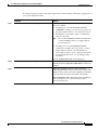
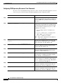
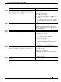
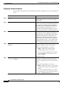
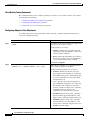
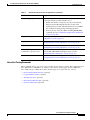
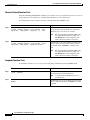
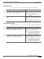
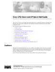
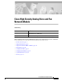
Cisco High-Density Analog Voice and Fax
Network Module
Feature History
Release
Modification
12.2(2)XT
These features were implemented on the Cisco 2600 series, Cisco
3640 and the Cisco 3660 router.
12.2(8)T
This feature was integrated into Cisco IOS Release 12.2(8)T.
This document describes the Cisco High-Density Analog Voice and Fax Network Module (NM-HDA)
in Cisco IOS Release 12.2(8)T. This document includes the following sections:
•
Feature Overview, page 2
•
Supported Platforms, page 9
•
Supported Standards, MIBs, and RFCs, page 10
•
Prerequisites, page 10
•
Configuration Tasks, page 11
•
Configuration Examples, page 29
•
Command Reference, page 31
•
Glossary, page 37
Cisco IOS Release 12.2(2)XT and 12.2(8)T
1
Cisco High-Density Analog Voice and Fax Network Module
Feature Overview
Feature Overview
The Cisco High-Density Analog Voice and Fax Network Module provides DTMF detection, voice
compression and decompression, call progress tone generation, voice activity detection (VAD), echo
cancellation, and adaptive jitter buffering for up to 16 ports.
The following port combinations are supported:
•
Twelve Foreign Exchange Station (FXS) ports
•
Eight Foreign Exchange Office (FXO) ports and four FXS ports
•
Twelve FXS and four FXO ports
•
Four Foreign Exchange Station (FXS) ports
The base card supports four FXS ports. The addition of an eight-port FXS expansion module can
increase the capacity to twelve FXS ports. The addition of two four-port FXO expansion modules can
increase the capacity to eight- FXO ports and four-FXS ports. The addition of one each of the FXS and
FXO expansion modules can increase the capacity to twelve FXS ports and four- FXO ports. The FXO
expansion module supports a power failure port which connects directly to the central office (CO) in case
of failure.
The digital signal processors (DSPs) on the network module support up to eight-ports of
high-complexity codecs or up to sixteen ports of medium-complexity and low-complexity codecs. The
number of DSPs must be increased if more than eight ports of high-complexity codecs are needed. In
this case, a DSP expansion module must be installed.
Table 1 shows analog voice port numbering, which differs for each of the voice-enabled routers. More
current information may be available in the release notes that accompany the Cisco IOS software you
are using.
Table 1
Caution
Base Module
Telephony Signaling
Interface
Voice Port Numbers
NM-HDA-4FXS
FXS
0 to 3
EM0
FXO
4 to 7
EM0
FXS
4 to 11
EM1
FXO
14 to 17
EM1
FXS
14 to 21
No more than a total of 12 FXS ports can be configured at one time.
Cisco IOS Release 12.2(2)XT and 12.2(8)T
2
High-Density Analog Voice Port Numbering
Cisco High-Density Analog Voice and Fax Network Module
Feature Overview
Telephony Signaling Interfaces
Voice ports on routers and access servers physically connect the router or access server to telephony
devices such as telephones, fax machines, PBXs, and (PSTN) central office (CO) switches. These
devices may use any of several types of signaling interfaces to generate information about on-hook
status, ringing, and line seizure.
The router’s voice-port hardware and software must be configured to transmit and receive the same type
of signaling being used by the device with which they are interfacing so that calls can be exchanged
smoothly between the packet network and the circuit-switched network.
The signaling interfaces discussed in this document include foreign exchange office (FXO), and foreign
exchange station (FXS), which are types of analog interfaces. It is important to know which signaling
method the telephony side of the connection is using and to match the router configuration and voice
interface hardware to that signaling method.
The next three illustrations show how the different signaling interfaces are associated with different uses
of voice ports. In Figure 1, FXS signaling is used for end-user telephony equipment, such as a telephone
or fax machine. Figure 2 shows an FXS connection to a telephone and an FXO connection to the PSTN
at the far side of a WAN; this might be a telephone at a local office going over a WAN to a router at
headquarters that connects to the PSTN.
FXS Signaling Interfaces
WAN
V
FXS
Figure 2
Serial or Voice port
Ethernet port 1/0/0
V
37757
Voice port Serial or
1/0/0 Ethernet port
FXS
FXS and FXO Signaling Interfaces
Voice port Serial or
1/0/0 Ethernet port
FXS
V
Serial or Voice port
Ethernet port 1/0/0
WAN
V
FXO
PSTN
37758
Figure 1
FXS and FXO Interfaces
An FXS interface connects the router or access server to end-user equipment such as telephones, fax
machines, or modems. The FXS interface supplies ring, voltage, and dial tone to the station and includes an
RJ-11 connector for basic telephone equipment, keysets, and PBXs.
An FXO interface is used for trunk, or tie line, connections to a PSTN CO or to a PBX. This interface is
of value for off-premise station applications. A standard RJ-11 modular telephone cable connects the FXO
voice interface card to the PSTN or PBX through a telephone wall outlet.
Cisco IOS Release 12.2(2)XT and 12.2(8)T
3
Cisco High-Density Analog Voice and Fax Network Module
Feature Overview
FXO and FXS interfaces indicate on-hook or off-hook status and the seizure of telephone lines by one
of two access signaling methods: loop start or ground start. The type of access signaling is determined
by the type of service from the CO; standard home telephone lines use loop start, but business telephones
can order ground start lines instead.
Loop-start is the more common of the access signaling techniques. When a handset is picked up (the
telephone goes off-hook), this action closes the circuit that draws current from the telephone company
CO and indicates a change in status, which signals the CO to provide dial tone. An incoming call is
signaled from the CO to the handset by sending a signal in a standard on/off pattern, which causes the
telephone to ring.
Loop-start has two disadvantages, however, that usually are not a problem on residential telephones but
that become significant with the higher call volume experienced on business telephones. Loop-start
signaling has no means of preventing two sides from seizing the same line simultaneously, a condition
known as glare. Also, loop-start signaling does not provide switch-side disconnect supervision for FXO
calls. The telephony switch (the connection in the PSTN, another PBX, or key system) expects the
router’s FXO interface, which looks like a telephone to the switch, to hang up the calls it receives through
its FXO port. However, this function is not built into the router for received calls; it only operates for
calls originating from the FXO port.
Another access signaling method used by FXO and FXS interfaces to indicate on-hook or off-hook status
to the CO is ground start signaling. It works by using ground and current detectors that allow the network
to indicate off-hook or seizure of an incoming call independent of the ringing signal and allow for
positive recognition of connects and disconnects. For this reason, ground-start signaling is typically used
on trunk lines between PBXs and in businesses where call volume on loop start lines can result in glare.
See the “Configuring Disconnect Supervision Commands” section on page 14 and “Configuring FXO
Supervisory Disconnect Tone Commands” section on page 16 for voice port commands that configure
additional recognition of disconnect signaling.
In most cases, the default voice port command values are sufficient to configure FXO and FXS voice
ports.
Disconnect Supervision Commands
PBX and PSTN switches use several different methods to indicate that a call should be disconnected
because one or both parties have hung up. The commands in this section are used to configure the router
to recognize the type of signaling in use by the PBX or PSTN switch connected to the voice port. These
methods include the following:
•
Battery reversal disconnect
•
Battery denial disconnect
•
Supervisory tone disconnect (STD)
Battery reversal occurs when the connected switch changes the polarity of the line in indicate changes
in call state (such as off-hook or, in this case, call disconnect). This is the signaling looked for when the
battery reversal command is enabled on the voice port, which is the default configuration.
Battery denial (sometimes called power denial) occurs when the connected switch provides a short
(approximately 600 ms) interruption of line power to indicate a change in call state. This is the signaling
looked for when the supervisory disconnect command is enabled on the voice port, which is the default
configuration.
Cisco IOS Release 12.2(2)XT and 12.2(8)T
4
Cisco High-Density Analog Voice and Fax Network Module
Feature Overview
Supervisory tone disconnect occurs when the connected switch provides a special tone to indicate a
change in call state. Some PBXs and PSTN CO switches provide a 600-millisecond interruption of line
power as a supervisory disconnect, and others provide supervisory tone disconnect (STD). This is the
signal that the router is looking for when the no supervisory disconnect command is configured on the
voice port.
Note
In some circumstances, you can use the FXO Disconnect Supervision feature to enable analog FXO
ports to monitor call progress tones for disconnect supervision that are returned from a PBX or from
the PSTN. For more information, see the “Configuring FXO Supervisory Disconnect Tone
Commands” section on page 16.
FXO Supervisory Disconnect Tone Commands
If the FXO supervisory disconnect tone is configured and a detectable tone from the PSTN or PBX is
detected by the Digital Signal Processor (DSP), the analog FXO port goes on-hook. This feature prevents
an analog FXO port from remaining in an off-hook state after an incoming call is ended. FXO
supervisory disconnect tone enables interoperability with PSTN and PBX systems whether or not they
transmit supervisory tones.
Note
This feature applies only to analog FXO ports with loop-start signaling on the Cisco 2600 series, the
Cisco 3640, and the Cisco 3660 routers.
To configure a voice port to detect incoming tones, you must know the parameters of the tones expected
from the PBX or PSTN. Then create a voice class that defines the tone- detection parameters, and,
finally, apply the voice class to the applicable analog FXO voice ports. This procedure configures the
voice port to go on-hook when it detects the specified tones. The parameters of the tones need to be
precisely specified to prevent unwanted disconnects due to detection of nonsupervisory tones or noise.
A supervisory disconnect tone is normally a dual tone consisting of two frequencies; however, tones of
only one frequency can also be detected. Use caution if you configure voice ports to detect nondual
tones, because unwanted disconnects can result from detection of random tone frequencies. You can
configure a voice port to detect a tone with one on/off time cycle, or you can configure it to detect tones
in a cadence pattern with up to four on/off time cycles.
Delay in Voice Networks
Delay is the time it takes for voice packets to travel between two endpoints. Excessive delay can cause
quality problems with real-time traffic such as voice. However, because of the speed of network links
and the processing power of intermediate devices, some delay is expected.
When listening to speech, the human ear normally accepts up to about 150 ms of delay without noticing
delays. The ITU G.114 standard recommends no more than 150 ms of one-way delay for a normal voice
conversation. Once the delay exceeds 150 ms, a conversation is more like a “walkie-talkie” conversation
in which one person must wait for the other to stop speaking before beginning to talk.
You can measure delay fairly easily by using ping tests at various times of the day with different network
traffic loads. If network delay is excessive, it must be reduced for adequate voice quality.
Cisco IOS Release 12.2(2)XT and 12.2(8)T
5
Cisco High-Density Analog Voice and Fax Network Module
Feature Overview
Several different types of delay combine to make up the total end-to-end delay associated with voice
calls:
Note
•
Propagation delay—Amount of time it takes the data to physically travel over the media.
•
Handling delay—Amount of time it takes to process data by adding headers, taking samples,
forming packets, and so on.
•
Queuing delay—Amount of time lost due to congestion.
•
Variable delay or jitter—Amount of time that causes the conversation to break and become
unintelligible. Jitter is described in detail below.
Propagation, handling, and queuing delay are not addressed by voice-port commands and fall outside
the scope of this document.
Voice Level Adjustment
As much as possible, it is desirable to achieve a uniform input decibel level to the packet voice network
to limit or eliminate any voice distortion due to incorrect input and output decibel levels. Adjustments
to levels may be required by the type of equipment connected to the network or by local country-specific
conditions.
Incorrect input or output levels can cause echo, as can an impedance mismatch. Too much input gain can
cause clipped or fuzzy voice quality. If the output level is too high at the remote router’s voice port, the
local caller hears echo. If the local router’s voice port input decibel level is too high, the remote side
hears clipping. If the local router’s voice port input decibel level is too low, or the remote router’s output
level is too low, the remote side voice can be distorted at a very low volume and Dual Tone
Multi-Frequency (DTMF) may be missed.
Echo Cancellation
Echo is the sound of your own voice reverberating in the telephone receiver while you are talking. When
timed properly, echo is not a problem in the conversation; however, if the echo interval exceeds
approximately 25 milliseconds, it is distracting. Echo is controlled by echo cancellers.
In the traditional telephony network, echo is generally caused by an impedance mismatch when the
4-wire network is converted to the 2-wire local loop. In voice packet-based networks, echo cancellers
are built into the low-bit rate codecs and are operated on each DSP.
Adaptive Jitter Buffering
Delay can cause unnatural starting and stopping of conversations, but variable-length delays (also known
as jitter) can cause a conversation to break and become unintelligible. Jitter is not usually a problem with
PSTN calls because the bandwidth of calls is fixed and each call has a dedicated circuit for the duration
of the call. However, in Voice over IP (VoIP) networks, data traffic might be bursty, and jitter from the
packet network can become an issue. Especially during times of network congestion, packets from the
same conversation can arrive at different interpacket intervals, disrupting the steady, even delivery
needed for voice calls. Cisco voice gateways have built-in jitter buffering to compensate for a certain
amount of jitter; the playout-delay command can be used to adjust the jitter buffer.
Cisco IOS Release 12.2(2)XT and 12.2(8)T
6
Cisco High-Density Analog Voice and Fax Network Module
Feature Overview
Normally, the defaults in effect are sufficient for most networks. However, a small playout delay from
the jitter buffer can cause lost packets and choppy audio, and a large playout delay can cause
unacceptably high overall end-to-end delay.
Note
Prior to Cisco IOS Release 12.1(5)T, playout delay was configured in voice-port configuration mode.
For Cisco IOS Release 12.1(5)T and later releases, in most cases, playout delay should be configured
in dial-peer configuration mode on the VoIP dial peer that is on the receiving end of the voice traffic
that is to be buffered. This dial peer senses network conditions and relays them to the DSPs, which
adjust the jitter buffer as necessary. When multiple applications are configured on the gateway,
playout delay should be configured in dial-peer configuration mode. When there are numerous dial
peers to configure, it might be simpler to configure playout delay on a voice port. If there are
conflicting playout delay configurations on a voice port and also on a dial peer, the dial peer
configuration takes precedence.
Voice Activity Detection Commands
In normal voice conversations, only one person speaks at a time. Today’s circuit-switched telephone
networks dedicate a bidirectional, 64-kbps channel for the duration of each conversation, regardless of
whether anyone is speaking at the moment. This means that, in a normal voice conversation, at least
50 percent of the bandwidth is wasted when one or both parties are silent. This figure can actually be
much higher when normal pauses and breaks in conversation are taken into account.
Packet-switched voice networks, on the other hand, can use this “wasted” bandwidth for other purposes
when voice activity detection (VAD) is configured. VAD works by detecting the magnitude of speech in
decibels and deciding when to cut off the voice from being framed. VAD has some technological
problems, however, which include the following:
•
General difficulties in determining when speech ends
•
Clipped speech when VAD is slow to detect that speech is beginning again
•
Automatic disabling of VAD when conversations take place in noisy surroundings
Benefits
Cost Effective
•
Higher density of analog interfaces provides voice and data over a single network
– 16 analog voice ports in a single network module (NM)
•
Connects existing analog voice telephone sets, fax machines, and key systems using Cisco gateways
Scalability-Modularity and Flexibility
•
Eliminates the need for a channel bank
•
The network module may be configured to be an FXO, an FXS or a combination module
Serviceability
•
Provides remote monitoring, testing, and diagnoses
Cisco IOS Release 12.2(2)XT and 12.2(8)T
7
Cisco High-Density Analog Voice and Fax Network Module
Feature Overview
Restrictions
The following features not supported at this time:
•
ATM SVC
•
SAS signaling
Supported High-Complexity Codecs
•
G.711 a-law
•
G.711 u-law
•
G.723.1 ANNEX-A 5300 bps
•
G.723.1 ANNEX-A 6300 bps
•
G.723.1 5300 bps
•
G.723.1 6300 bps
•
G.726 16000 bps
•
G.726 24000 bps
•
G.726 32000 bps
•
G.728 16000 bps
•
G.729 ANNEX-B 8000 bps
•
G.729 8000 bps
•
GSMFR 13200 bps
Supported Medium-Complexity Codecs:
•
G.726 16000 bps
•
G.726 24000 bps
•
G.726 32000 bps
•
G.729 ANNEX-B 8000 bps (Annex A version)
•
G.729 8000 bps (Annex A version)
Supported low-Complexity Codecs:
Note
•
G.711 a-law 64000 bps
•
G.711 u-law 64000 bps
Three-way calling is not supported with low-complexity codecs.
The ring capacity is 10 Ringer Equivalency Number (REN). The total of all RENs of the telephones
connected to the one line must not exceed the value 5, or some or all of the ringers may not operate.
Cisco IOS Release 12.2(2)XT and 12.2(8)T
8
Cisco High-Density Analog Voice and Fax Network Module
Supported Platforms
Related Documents
For information about installing voice network modules and voice interface cards in Cisco 2600 series,
Cisco 3640 and Cisco 3660 routers, see these publications:
•
Cisco 2600 Series Hardware Installation Guide
•
Cisco 3620 and Cisco 3640 Modular Access Routers Quick Start Guide
•
Cisco 3600 Series Hardware Installation Guide
•
Update to the Cisco Network Module Hardware Installation Guide
•
WAN Interface Card Hardware Installation Guide
For information about configuring Voice features, see these publications:
•
Cisco 2600 Series Software Configuration Guide
•
Cisco IOS Release 12.2 Voice, Video, and Fax Configuration Guide
•
Cisco IOS Release 12.2 Voice, Video, and Fax Command Reference Guide
Supported Platforms
•
Cisco 2600 series
•
Cisco 3640
•
Cisco 3660
Determining Platform Support Through Cisco Feature Navigator
Cisco IOS software is packaged in feature sets that support specific platforms. To get updated
information regarding platform support for this feature, access Cisco Feature Navigator. Cisco Feature
Navigator dynamically updates the list of supported platforms as new platform support is added for the
feature.
Cisco Feature Navigator is a web-based tool that enables you to quickly determine which Cisco IOS
software images support a specific set of features and which features are supported in a specific
Cisco IOS image. You can search by feature or release. Under the release section, you can compare
releases side by side to display both the features unique to each software release and the features in
common.
To access Cisco Feature Navigator, you must have an account on Cisco.com. If you have forgotten or
lost your account information, send a blank e-mail to [email protected]. An automatic check
will verify that your e-mail address is registered with Cisco.com. If the check is successful, account
details with a new random password will be e-mailed to you. Qualified users can establish an account
on Cisco.com by following the directions at http://www.cisco.com/register.
Cisco Feature Navigator is updated regularly when major Cisco IOS software releases and technology
releases occur. For the most current information, go to the Cisco Feature Navigator home page at the
following URL:
http://www.cisco.com/go/fn
Cisco IOS Release 12.2(2)XT and 12.2(8)T
9
Cisco High-Density Analog Voice and Fax Network Module
Supported Standards, MIBs, and RFCs
Table 2 lists the hardware platforms that support this feature, and the releases in which the feature was
first supported. If the First T train Release column is blank, the feature is not yet available in a Cisco IOS
T release on that platform.
Table 2
Cisco IOS Release and Platform Support for this Feature
Platform
12.2(2)XT
12.2(8)T
Cisco 2600 series
X
X
Cisco 3640
X
X
Cisco 3660
X
X
Supported Standards, MIBs, and RFCs
Standards
•
No new or modified Standards are supported by this feature.
MIBs
•
No new or modified MIBs are supported by this feature.
To obtain lists of supported MIBs by platform and Cisco IOS release, and to download MIB modules,
go to the Cisco MIB website on Cisco.com at the following URL:
http://www.cisco.com/public/sw-center/netmgmt/cmtk/mibs.shtml
RFCs
•
No new or modified RFCs are supported by this feature.
•
Obtain analog line or analog trunk service from your PBX, Key System, or PSTN.
•
Complete your company’s dial plan.
•
Establish a working telephony network based on your company’s dial plan.
•
Install at least one other network module or WAN interface card to provide the connection to the
network LAN or WAN.
•
Establish a working IP and Frame Relay or ATM network. For more information about configuring
IP, refer to the Cisco IOS IP Configuration Guide, Release 12.2.
•
Install appropriate voice processing and voice interface hardware on the router. See the
“Configuring Analog FXO and FXS Voice Ports” section on page 11.
Prerequisites
Cisco IOS Release 12.2(2)XT and 12.2(8)T
10
Cisco High-Density Analog Voice and Fax Network Module
Configuration Tasks
Configuration Tasks
See the following sections for configuration tasks for this feature.
•
Configuring Analog FXO and FXS Voice Ports (required)
•
Configuring Voice Activity Detection (VAD) (optional)
•
Fine-Tuning Analog Voice Ports (optional)
•
Verifying Analog Voice-Port Configurations (optional)
Configuring Analog FXO and FXS Voice Ports
To configure basic analog voice port parameters on Cisco 2600 series, Cisco 3640 and
Cisco 3660 routers, use the following commands beginning in global configuration mode:
Step 1
Command
Purpose
Router(config)# voice-port slot/subunit/port
Enters voice-port configuration mode.
The arguments are as follows:
•
slot—Specifies the number of the router slot
where the voice network module is installed.
•
port—Indicates the voice port. See Table 1 on
page 2 for valid entries.
•
subunit—Specifies the location of the
Cisco High-Density Analog Voice/Fax Netwo
rk Module (NM-HDA). The valid entry is 0.
Note
A slash must be entered between
arguments.
Valid entries vary by router platform; enter the
show voice port summary command for
available values.
Step 2
FXO or FXS
Router(config-voiceport)# signal {loop-start |
ground-start}
Step 3
Router(config-voiceport)# cptone locale
Selects the access signaling type to match that of
the telephony connection you are making. The
keywords are as follows:
•
loop-start—(default) Uses a closed circuit to
indicate off-hook status; used for residential
loops.
•
ground-start—Uses ground and current
detectors; preferred for PBXs and trunks.
Selects the two-letter locale for the voice call
progress tones and other locale-specific parameters
to be used on this voice port.
Cisco routers comply with the ISO 3166 locale
name standards. To see valid choices, enter a
question mark (?) following the cptone command.
The default is us.
Cisco IOS Release 12.2(2)XT and 12.2(8)T
11
Cisco High-Density Analog Voice and Fax Network Module
Configuration Tasks
Step 4
Command
Purpose
Router(config-voiceport)# ring frequency {25 | 50}
(FXS only) Selects the ring frequency, in hertz
(HZ), used on the FXS interface. This number must
match the connected telephony equipment and may
be country-dependent. If not set properly, the
attached telephony device may not ring or it may
buzz.
The keyword default is 25 on Cisco 2600 series,
Cisco 3640 and Cisco 3660 routers.
Step 5
Router(config-voiceport)# ring number number
(FXO only) Specifies the maximum number of
rings to be detected before an incoming call is
answered by the router.
The default is 1.
Step 6
Router(config-voiceport)# ring cadence {[pattern01 |
pattern02 | pattern03 | pattern04 | pattern05 |
pattern06 | pattern07 | pattern08 | pattern09 |
pattern10 | pattern11 | pattern12] | [define pulse
interval]}
(FXS only) Specifies an existing pattern for ring, or
defines a new one. Each pattern specifies a
ring-pulse time and a ring-interval time. The
keywords and arguments are as follows:
•
pattern01 through pattern12 name pre-set
ring cadence patterns. Enter ring cadence ? to
see ring pattern explanations.
•
define pulse interval specifies a user-defined
pattern: pulse is a number (one or two digits,
from 1 to 50) specifying ring pulse (on) time in
hundreds of milliseconds, and interval is a
number (one or two digits from 1 to 50)
specifying ring interval (off) time in hundreds
of milliseconds.
The default is the pattern specified by the cptone
locale that has been configured.
Step 7
Router(config-voiceport)# description string
Attaches a text string to the configuration that
describes the connection for this voice port. This
description appears in various displays and is
useful for tracking the purpose or use of the voice
port. The string argument is a character string from
1 to 255 characters in length.
The default is that there is no text string (describing
the voice port) attached to the configuration.
Step 8
Router(config-voiceport)# no shutdown
Cisco IOS Release 12.2(2)XT and 12.2(8)T
12
Activates the voice port. If a voice port is not being
used, shut the voice port down with the shutdown
command.
Cisco High-Density Analog Voice and Fax Network Module
Configuration Tasks
Configuring Voice Activity Detection (VAD)
Voice activity detection (VAD) is configured on dial peers; by default it is enabled. For more
information, see the “Configuring Dial Plans, Dial Peers, and Digit Manipulation” chapter in the
Cisco IOS Release 12.2 Voice, Video, and Fax Configuration Guide, Release 12.2. Two parameters
associated with VAD, music threshold and comfort noise, are configured on voice ports.
If VAD is enabled, use the following commands to adjust parameter values associated with VAD,
beginning in voice-port configuration mode:
Command
Purpose
Step 1
Router(config-voiceport)# music-threshold number
Specifies the minimal decibel level of music played
when calls are put on hold. The decibel level affects
how voice activity detection (VAD) treats the music
data. Valid entries range from –70 to –30. When
used with VAD, if the level is set too high, the
remote end hears no music; if it is set too low, there
is unnecessary voice traffic. The default is –38.
Step 2
Router(config-voiceport)# comfort-noise
This parameter creates subtle background noise to
fill silent gaps during calls when VAD is enabled on
voice dial peers. If comfort noise is not generated,
the resulting silence can fool the caller into
thinking the call is disconnected instead of being
merely idle. The default is that comfort noise is
enabled.
Fine-Tuning Analog Voice Ports
Normally, default parameter values for voice ports are sufficient for most networks. Depending on the
specifics of your particular network, however, you may need to adjust certain parameters that are
configured on voice ports. Collectively, these commands are referred to as voice-port tuning commands.
Note
The commands, keywords, and arguments that you are able to use may differ slightly from those
presented here, based on your platform, Cisco IOS release, and configuration. When in doubt, use
Cisco IOS command help (command ?) to determine the syntax choices that are available.
The voice-port tuning commands are grouped into these categories and explained in the following
sections:
•
Configuring Disconnect Supervision Commands (optional)
•
Configuring FXO Supervisory Disconnect Tone Commands (optional)
•
Configuring Timeouts Commands (optional)
•
Timing Commands (optional)
•
Voice Quality Tuning Commands (optional)
Full descriptions of the commands in this section can be found in the Cisco IOS Voice, Video, and Fax
Command Reference, Release 12.2.
Cisco IOS Release 12.2(2)XT and 12.2(8)T
13
Cisco High-Density Analog Voice and Fax Network Module
Configuration Tasks
Configuring Disconnect Supervision Commands
PBX and PSTN switches use several different methods to indicate that a call should be disconnected
because one or both parties have hung up. The commands in this section are used to configure the router
to recognize the type of signaling in use by the PBX or PSTN switch connected to the voice port. These
methods include the following:
•
Battery reversal disconnect
•
Battery denial disconnect
•
Supervisory tone disconnect (STD)
Battery reversal occurs when the connected switch changes the polarity of the line to indicate changes
in call state (such as off-hook or, in this case, call disconnect). This is the signaling looked for when the
battery reversal command is enabled on the voice port, which is the default configuration.
Battery denial (sometimes called power denial) occurs when the connected switch provides a short
(approximately 600 ms) interruption of line power to indicate a change in call state. This is the signaling
looked for when the supervisory disconnect command is enabled on the voice port, which is the default
configuration.
Supervisory tone disconnect occurs when the connected switch provides a special tone to indicate a
change in call state. Some PBXs and PSTN CO switches provide a 600-millisecond interruption of line
power as a supervisory disconnect, and others provide supervisory tone disconnect (STD). This is the
signal that the router is looking for when the no supervisory disconnect command is configured on the
voice port.
Note
In some circumstances, you can use the FXO Disconnect Supervision feature to enable analog FXO
ports to monitor call progress tones for disconnect supervision that are returned from a PBX or from
the PSTN. For more information, see the “Configuring FXO Supervisory Disconnect Tone
Commands” section on page 16.
Cisco IOS Release 12.2(2)XT and 12.2(8)T
14
Cisco High-Density Analog Voice and Fax Network Module
Configuration Tasks
To change parameters related to disconnect supervision, use the following commands as appropriate, in
voice-port configuration mode:
Step 1
Command
Purpose
Router(config-voiceport)# battery-reversal
Enables battery reversal. The default is that battery
reversal is enabled.
•
Note
•
For FXO ports—Use the no battery-reversal
command to configure a loop-start voice port to not
disconnect when it detects a second battery reversal.
The default is to disconnect when a second battery
reversal is detected.
Also use the no battery-reversal command when
a connected FXO port does not support battery
reversal detection.
For FXS ports—Use the no battery-reversal
command to configure the voice port not to reverse
battery when it connects calls. The default is to
reverse battery when a call is connected, then return
to normal when the call is over, providing positive
disconnect.
See also the disconnect-ack command (Step 7).
Step 2
Router(config-voiceport)# supervisory disconnect
(FXO only) Enables the PBX or PSTN switch to provide
STD. By default the supervisory disconnect command is
enabled.
Step 3
Router(config-voiceport)# disconnect-ack
(FXS only) Configures the voice port to return an
acknowledgment upon receipt of a disconnect signal. The
FXS port removes line power if the equipment on the FXS
loop-start trunk disconnects first. This is the default.
The no disconnect-ack command prevents the FXS port
from responding to the on-hook disconnect with a
removal of line power.
Cisco IOS Release 12.2(2)XT and 12.2(8)T
15
Cisco High-Density Analog Voice and Fax Network Module
Configuration Tasks
Configuring FXO Supervisory Disconnect Tone Commands
To create a voice class that defines the specific tone or tones to be detected and then apply the voice class
to the voice port, use the following commands beginning in global configuration mode:
Command
Purpose
Step 1
Router(config)# voice class dualtone tag
Creates a voice class for defining one tone
detection pattern. The range for the tag number is
from 1 to 10000. The tag number must be unique on
the router.
Step 2
Router(config-voice-class)# freq-pair tone-id
frequency-1 frequency-2
Specifies the two frequencies, in Hz, for a tone to
be detected (or one frequency if a nondual tone is
to be detected). If the tone to be detected contains
only one frequency, enter 0 for frequency-2. The
arguments are as follows:
•
tone-id—Ranges from 1 to 16. There is no
default.
•
frequency-1 and frequency-2—Ranges from
300 to 3600, or you can enter 0 for
frequency-2. There is no default.
Note
Repeat this command for each additional
tone to be specified.
Step 3
Router(config-voice-class)# freq-max-deviation
frequency
Specifies the maximum frequency deviation that
will be detected, in Hz. The frequency argument
ranges from 10 to 125. The default is 10.
Step 4
Router(config-voice-class)# freq-max-power dBmO
Specifies the maximum tone power that will be
detected, in dBmO. The dBmO argument ranges
from 0 to 20. The default is 10.
Step 5
Router(config-voice-class)# freq-min-power dBmO
Specifies the minimum tone power that will be
detected, in dBmO. The dBmO argument ranges
from 10 to 35. The default is 30.
Step 6
Router(config-voice-class)# freq-power-twist dBmO
Specifies the power difference allowed between the
two frequencies, in dBmO. The dBmO argument
ranges from 0 to 15. The default is 6.
Step 7
Router(config-voice-class)# freq-max-delay time
Specifies the timing difference allowed between
the two frequencies, in 10-millisecond increments.
The time argument ranges from 10 to 100 (100 ms
to 1 sec). The default is 20 (200 ms).
Step 8
Router(config-voice-class)# cadence-min-on-time time
Specifies the minimum tone on time that will be
detected, in 10-millisecond increments. The time
argument ranges from 0 to 100 (0 ms to 1 sec).
Step 9
Router(config-voice-class)# cadence-max-off-time time
Specifies the maximum tone off time that will be
detected, in 10-millisecond increments. The time
argument ranges from 0 to 5000 (0 ms to 50 sec).
Cisco IOS Release 12.2(2)XT and 12.2(8)T
16
Cisco High-Density Analog Voice and Fax Network Module
Configuration Tasks
Step 10
Command
Purpose
Router(config-voice-class)# cadence-list cadence-id
cycle-1-on-time cycle-1-off-time cycle-2-on-time
cycle-2-off-time cycle-3-on-time cycle-3-off-time
cycle-4-on-time cycle-4-off-time
(Optional) Specifies a tone cadence pattern to be
detected. Specify an on time and off time for each
cycle of the cadence pattern.
The arguments are as follows:
•
cadence-id—Ranges from 1 to 10. There is no
default.
•
cycle-N-on-time and cycle-N-off-time—Range
from 0 to 1000 (0 ms to 10 sec). The default is
0.
Step 11
Router(config-voice-class)# cadence-variation time
(Optional) Specifies the maximum time that the
tone onset can vary from the specified onset time
and still be detected, in 10-millisecond increments.
The time argument ranges from 0 to 200 (0 ms to 2
sec). The default is 0.
Step 12
Router(config-voice-class)# exit
Exits voice class configuration mode.
Step 13
Router(config)# voice-port slot/subunit/port
Enters voice-port configuration mode.
The arguments are as follows:
Step 14
Router(config-voiceport)# supervisory disconnect
dualtone {mid-call | pre-connect} voice-class tag
•
slot—Specifies the slot number where the
voice network module is installed.
•
subunit—Specifies the
Cisco High-Density Analog Voice/Fax Netwo
rk Module (NM-HDA) where the voice port is
located.
•
port—Identifies the analog voice-port number.
See Table 1 on page 2 for valid entries.
Assigns an FXO supervisory disconnect tone voice
class to the voice port.
The keywords are as follows:
Step 15
Router(config-voiceport)# supervisory disconnect
anytone
•
mid-call—Specifies tone detection during the
entire call.
•
pre-connect—Specifies tone detection only
during call setup.
Configures the voice port to disconnect on receipt
of any tone.
Cisco IOS Release 12.2(2)XT and 12.2(8)T
17
Cisco High-Density Analog Voice and Fax Network Module
Configuration Tasks
Configuring Timeouts Commands
To change timeouts parameters, use the following commands as appropriate, in voice-port configuration
mode:
Command
Purpose
Step 1
Router(config-voiceport)# timeouts call-disconnect
seconds
Configures the call disconnect timeout value in
seconds. Valid entries range from 0 to 120. The
default is 60.
Step 2
Router(config-voiceport)# timeouts initial seconds
Sets the number of seconds that the system waits
between the caller input of the initial digit and the
subsequent digit of the dialed string. If the wait
time expires before the destination is identified, a
tone sounds and the call ends. The seconds
argument is the initial timeout duration. A valid
entry is an integer from 0 to 120. The default is 10.
Step 3
Router(config-voiceport)# timeouts interdigit seconds
Configures the number of seconds that the system
waits after the caller has input the initial digit or a
subsequent digit of the dialed string. If the timeout
ends before the destination is identified, a tone
sounds and the call ends. This value is important
when using variable-length dial-peer destination
patterns (dial plans). The seconds argument is the
interdigit timeout wait time in seconds. A valid
entry is an integer from 0 to 120. The default is 10.
Step 4
Router(config-voiceport)# timeouts ringing {seconds |
infinity}
Specifies the duration that the voice port allows
ringing to continue if a call is not answered.
The keyword and argument are as follows:
•
infinity—Indicates that ringing should
continue until the caller goes on hook.
•
seconds—Specifies the number of seconds to
allow ringing without answer. The range is
from 5 to 60000.
The default is 180.
Step 5
Router(config-voiceport)# timeouts wait-release
{seconds | infinity}
Specifies the duration that a voice port stays in the
call-failure state while the Cisco device sends a
busy tone, reorder tone, or an out-of-service tone to
the port.
The keyword and argument are as follows:
Cisco IOS Release 12.2(2)XT and 12.2(8)T
18
•
infinity—Indicates that the voice port should
not be released as long as the call-failure state
remains.
•
seconds—Specifies the number of seconds to
allow before the call is released. The range is
from 3 to 3600. The default is 30.
Cisco High-Density Analog Voice and Fax Network Module
Configuration Tasks
Timing Commands
To change timing parameters, use the following commands as appropriate, in voice-port configuration
mode:
Command
Purpose
Step 1
Router(config-voiceport)# timing dial-pulse min-delay
milliseconds
Specifies time, in milliseconds, between the
generation of wink-like pulses when the type is
pulse. Valid entries are from 0 to 5000. The default
is 300 for the Cisco 3600 series routers.
Step 2
Router(config-voiceport)# timing digit milliseconds
Specifies the DTMF digit signal duration in
milliseconds. Valid entries are from 50 to 100. The
default is 100.
Step 3
Router(config-voiceport)# timing guard-out
milliseconds
(FXO ports only) Specifies the duration in
milliseconds of the guard-out period that prevents
this port from seizing a remote FXS port before the
remote port detects a disconnect signal. The range
is from 300 to 3000. The default is 2000.
Step 4
Router(config-voiceport)# timing hookflash-out
milliseconds
Specifies the duration, in milliseconds, of the
hookflash. Valid entries are from 50 to 500. The
default is 300.
Step 5
Router(config-voiceport)# timing interdigit
milliseconds
Specifies the DTMF interdigit duration, in
milliseconds. Valid entries are from 50 to 500. The
default is 100.
Step 6
Router(config-voiceport)# timing pulse
pulses-per-second
(FXO only) Specifies the pulse dialing rate in
pulses per second. Valid entries are from 10 to 20.
The default is 20.
Step 7
Router(config-voiceport)# timing pulse-digit
milliseconds
(FXO only) Configures the pulse digit signal
duration. The range of the pulse digit signal
duration is from 10 to 20. The default is 20.
Step 8
Router(config-voiceport)# timing pulse-interdigit
(FXO only) Specifies pulse dialing interdigit
timing in milliseconds. Valid entries are from 100
to 1000. The default is 500.
Cisco IOS Release 12.2(2)XT and 12.2(8)T
19
Cisco High-Density Analog Voice and Fax Network Module
Configuration Tasks
Voice Quality Tuning Commands
The commands in this section configure parameters to improve voice quality. Common voice quality
issues include the following:
•
Configuring Adaptive Jitter Adjustment (optional)
•
Configuring Echo Adjustment (optional)
•
Configuring Voice Level Adjustment (optional)
Configuring Adaptive Jitter Adjustment
To configure the playout delay jitter buffer, use the following commands beginning in dial-peer or
voice-port configuration mode:
Step 1
Command
Purpose
Router(config-voiceport)# playout-delay mode {adaptive
| fixed}
Determines the mode in which the jitter buffer will
operate for calls on this voice port.
The keywords are as follows:
•
adaptive—Adjusts the jitter buffer size and
amount of playout delay during a call based on
current network conditions.
•
fixed—Defines the jitter buffer size as fixed so
that the playout delay does not adjust during a
call. A constant playout delay is added.
The default is adaptive.
Step 2
Router(config-voiceport)# playout-delay {nominal value
| maximum value | minimum {default | low | high}}
Tunes the playout buffer to accommodate packet
jitter caused by switches in the WAN.
The keywords and arguments are as follows:
Cisco IOS Release 12.2(2)XT and 12.2(8)T
20
•
nominal—Defines the amount of playout
delay applied at the beginning of a call by the
jitter buffer in the gateway. In fixed mode, this
is also the maximum size of the jitter buffer
throughout the call.
•
value—Specifies the range that depends on
type of DSP and configured codec complexity.
For medium codec complexity, the range is
from 0 to 150 ms. For high codec complexity
and DSPs that do not support codec
complexity, the range is from 0 to 250 ms.
•
maximum (adaptive mode only)—Specifies
the jitter buffer's upper limit (80 ms), or the
highest value to which the adaptive delay is set.
•
minimum (adaptive mode only)—Specifies
the jitter buffer's lower limit (10 ms), or the
lowest value to which the adaptive delay is set.
•
default—Specifies 40 ms.
Cisco High-Density Analog Voice and Fax Network Module
Configuration Tasks
Configuring Echo Adjustment
By design, echo cancellers are limited by the total amount of time they wait for the reflected speech to
be received, which is known as an echo trail. The echo trail is normally 32 milliseconds. In Cisco System
voice implementations, echo cancellers are enabled using the echo-cancel enable command, and echo
trails are configured using the echo-cancel coverage command.
To configure parameters related to the echo canceller, use the following commands beginning in
voice-port configuration mode:
Command
Purpose
Step 1
Router(config-voiceport)# echo-cancel enable
Enables the cancellation of voice that is sent and
received on the same interface. Echo cancellation
coverage must also be configured. The default is
that echo cancellation is enabled.
Step 2
Router(config-voiceport)# echo-cancel coverage {8 | 16
| 24 | 32}
Adjusts the echo canceller by the specified number
of milliseconds. The default is 16.
Step 3
Router(config-voiceport)# non-linear
Enables nonlinear processing (residual echo
suppression) in the echo canceller, which shuts off
any signal if no near-end speech is detected. Echo
cancelling must be enabled for this feature. The
default is that nonlinear processing is enabled.
Configuring Voice Level Adjustment
Use the input gain and output attenuation commands to adjust voice levels, and the impedance
command to set the impedance value to match that of the voice circuit to which the voice port connects.
To change parameters related to voice levels, use the following commands as appropriate, in voice-port
configuration mode:
Step 1
Command
Purpose
Router(config-voiceport)# input gain value
Specifies, in decibels, the amount of gain to be
inserted at the receiver side of the interface,
increasing or decreasing the signal. After an input
gain setting is changed, the voice call must be
disconnected and reestablished before the changes
take effect. The value argument is any integer from
–6 to 14. The default is 0.
Cisco IOS Release 12.2(2)XT and 12.2(8)T
21
Cisco High-Density Analog Voice and Fax Network Module
Configuration Tasks
Step 2
Command
Purpose
Router(config-voiceport)# output attenuation value
Specifies the amount of attenuation in decibels at
the transmit side of the interface, decreasing the
signal. A system-wide loss plan can be
implemented using the input gain and output
attenuation commands.
The default value for this command assumes that a
standard transmission loss plan is in effect,
meaning that normally there must be –6 dB
attenuation between phones.
The value argument is any integer from –6 to 14.
The default is 0.
Step 3
Router(config-voiceport)# impedance { 600r | complex1 }
Specifies the terminating impedance of a voice
port interface, which needs to match the
specifications from the specific telephony system
to which it is connected.
•
600r—Specifies 600 ohms real.
•
complex1—Specifies Complex 1.
The default is 600r.
Verifying Analog Voice-Port Configurations
After configuring the voice ports on your router, perform the following steps to verify proper operation:
Step 1
Pick up the handset of an attached telephony device and check for a dial tone.
Step 2
If you have dial tone, check for DTMF detection. If the dial tone stops when you dial a digit, then the
voice port is most likely configured properly.
Step 3
To identify port numbers of voice interfaces installed in your router, use the show voice port summary
command. For examples of the output, see the “Analog FXS Voice Port Example” section on page 30.
Step 4
To verify voice-port parameter settings, use the show voice port command with the appropriate syntax
from Table 3. For sample output, see the “Analog FXO Voice Port Example” section on page 29.
Table 3
Show Analog Voice Port Command Syntax
Platform
Command Syntax
Cisco 2600 series
show voice port [slot-number/subunit-number/port]
Cisco 3640
Cisco 3660
Step 5
To display voice-channel configuration information for all DSP channels, use the show voice dsp
command.
Router# show voice dsp
Cisco IOS Release 12.2(2)XT and 12.2(8)T
22
Cisco High-Density Analog Voice and Fax Network Module
Configuration Tasks
Step 6
To verify the call status for all voice ports, use the show voice call summary command.
Router# show voice call summary
Step 7
To display the contents of the active call table, which shows all of the calls currently connected through
the router or concentrator, use the show call active voice command.
Router# show call active voice
Step 8
To display the contents of the call history table, use the show call history voice command. To limit the
display to the last calls connected through this router, use the keyword last and define the number of
calls to be displayed with the argument number. To limit the display to a shortened version of the call
history table, use the brief keyword.
Router# show call history voice [last | number | brief]
Troubleshooting Tips
The following sections will assist in analyzing and troubleshooting voice port problems:
•
Troubleshooting Chart, page 24
•
Voice Port Testing Commands, page 25
To troubleshoot the high density analog network module, perform the following steps:
•
To display the ccaal2 function calls during call setup and teardown, use the debug ccaal2 session
privileged EXEC command.
•
To trace the state transition of the RAS state machine based on the processed events, use the debug
cch323 ras privileged EXEC command.
•
To enable debugging for DSP API message events, use the debug dspapi all EXEC command.
•
To display ASN1 contents of RAS and Q.931 messages, use the debug h255 asn1 privileged EXEC
command.
•
To enable debugging for Host Port Interface (HPI) message events, use the debug hpi all EXEC
command.
•
To display debugging information for all components of the Voice Call Manager, use the debug
voice all privileged EXEC command
•
To trace the execution path through the call control API, use the debug voip ccapi inout EXEC
command.
•
To trace error logs in the call control API, use the debug voip ccapi error EXEC command.
•
To enable debugging on all virtual voice port module (VPM) areas, use the debug vpm all
command.
•
To turn off all port level debugging, use the no debug vpm all command. It is usually a good idea
to turn off all debugging and then enter the debug commands you are interested in one by one. This
will help to avoid confusion about which ports you are actually debugging
•
To show messages from the digital signal processor (DSP) on the V.Fast Class (VFC) modem to the
router, use the debug vtsp dsp EXEC command.
Cisco IOS Release 12.2(2)XT and 12.2(8)T
23
Cisco High-Density Analog Voice and Fax Network Module
Configuration Tasks
To troubleshoot specific areas of the high density analog network module, perform the following steps:
•
To show messages from the DSP on the VPM to the router, Use the debug vpm dsp .
•
To show which debug commands are enabled, use the show debug.
•
To enable the display of trunk conditioning supervisory component trace information, use the debug
vtsp all.
Troubleshooting Chart
Table 4 lists some problems you might encounter after configuring voice ports and some suggested
remedies.
Table 4
Troubleshooting Voice Port Configurations
Problem
Suggested Action
No connectivity
Ping the associated IP address to confirm connectivity. If you
cannot successfully ping your destination, refer to the Cisco IOS
IP Configuration Guide, Release 12.2.
No connectivity
Enter the show voice port command with the voice port number
that you are troubleshooting, which will tell you:
If the voice port is up. If it is not, use the no shutdown
command to make it active.
•
What parameter values have been set for the voice port,
including default values (these do not appear in the output for
the show running-config command). If these values do not
match those of the telephony connection you are making,
reconfigure the voice port.
Telephony device buzzes or does
not ring
Use the show voice port command to confirm that ring frequency
is configured correctly. It must match the connected telephony
equipment and may be country-dependent.
Distorted speech
Use the show voice port command to confirm that the cptone
keyword setting (also called region tone) is US.
Music on hold is not heard
Reduce the music-threshold level.
Background noise is not heard
Enable the comfort-noise command.
Long pauses occur in
conversation; like speaking on a
walkie-talkie
Overall delay is probably excessive; the standard for adequate
voice quality is 150 ms one-way transit delay. Measure delay by
using ping tests at various times of the day with different network
traffic loads. If delay must be reduced, areas to examine include
propagation delay of signals between the sending and receiving
endpoints, voice encoding delay, and the voice packetization time
for various VoIP codecs.
Cisco IOS Release 12.2(2)XT and 12.2(8)T
24
•
Cisco High-Density Analog Voice and Fax Network Module
Configuration Tasks
Table 4
Troubleshooting Voice Port Configurations (continued)
Problem
Suggested Action
Jerky or choppy speech
Variable delay, or jitter, is being introduced by congestion in the
packet network. Two possible remedies are to:
•
Reduce the amount of congestion in your packet network.
Pings between VoIP endpoints will give an idea of the
round-trip delay of a link, which should never exceed 300 ms.
Also examine network queuing and dropped packets.
•
Increase the size of the jitter buffer with the playout-delay
command. (See the “Configuring Adaptive Jitter Adjustment”
section on page 20.)
Clipped or fuzzy speech
Reduce input gain. (See the “Configuring Voice Level
Adjustment” section on page 21.)
Clipped speech
Reduce the input level at the listener’s router. (See the
“Configuring Voice Level Adjustment” section on page 21.)
Volume too low or missed DTMF Increase speaker’s output level or listener’s input level. (See the
“Configuring Voice Level Adjustment” section on page 21.)
Echo interval is greater than 25 ms Configure the echo-cancel enable command and increase the
(sounds like a separate voice)
value for the echo-cancel coverage keyword. (See the
“Configuring Echo Adjustment” section on page 21.)
Too much echo
Reduce the output level at the speaker’s voice port. (See the
“Configuring Voice Level Adjustment” section on page 21.)
Voice Port Testing Commands
These commands allow you to force voice ports into specific states for testing. They require the use of
Cisco IOS Release 12.0(7)XK or 12.1(2)T or a later release, and they apply to Cisco 2600 series,
Cisco 3640, and Cisco 3660 routers. The following types of voice-port tests are covered:
•
Detector-Related Function Tests (optional)
•
Loopback Function Tests (optional)
•
Tone Injection Tests (optional)
•
Relay-Related Function Tests (optional)
•
Fax/Voice Mode Tests (optional)
Cisco IOS Release 12.2(2)XT and 12.2(8)T
25
Cisco High-Density Analog Voice and Fax Network Module
Configuration Tasks
Detector-Related Function Tests
Using the test voice port detector command, you are able to force a particular detector into an on or off
state, perform tests on the detector, and then return the detector to its original state.
To configure this feature, use the following commands in privileged EXEC mode:
Step 1
Command
Purpose
Router# test voice port slot/subunit/port detector
{m-lead | battery-reversal | loop-current | ring |
tip-ground | ring-ground | ring-trip} {on | off}
Identifies the voice port you want to test. Enter a
keyword for the detector under test and specify
whether to force it to the on or off state.
Note
Step 2
Router# test voice port slot/subunit/port detector
{m-lead | battery-reversal | loop-current | ring |
tip-ground | ring-ground | ring-trip} disable
For each signaling type (FXO, FXS), only
the applicable keywords are displayed.
The disable keyword is displayed only
when a detector is in the forced state.
Identifies the voice port on which you want to end
the test. Enter a keyword for the detector under
test and the keyword disable to end the forced
state.
Note
For each signaling type (FXO, FXS), only
the applicable keywords are displayed.
The disable keyword is displayed only
when a detector is in the forced state.
Loopback Function Tests
To establish loopbacks on a voice port, use the following commands in privileged EXEC mode:
Step 1
Command
Purpose
Router# test voice port slot/subunit/port loopback
{local | network}
Identifies the voice port you want to test and enters
a keyword for the loopback direction.
Note
Step 2
Router# test voice port slot/subunit/port loopback
disable
Cisco IOS Release 12.2(2)XT and 12.2(8)T
26
A call must be established on the voice
port under test.
Identifies the voice port on which you want to end
the test and enters the keyword disable to end the
loopback.
Cisco High-Density Analog Voice and Fax Network Module
Configuration Tasks
Tone Injection Tests
To inject a test tone into a voice port, use the following commands in privileged EXEC mode:
Step 1
Command
Purpose
Router# test voice port slot/subunit/port inject-tone
{local | network} {1000hz | 2000hz | 200hz | 3000hz |
300hz | 3200hz | 3400hz | 500hz | quiet}
Identifies the voice port you want to test and enters
keywords for the direction to send the test tone and
for the frequency of the test tone.
Note
Step 2
Router# test voice port slot/subunit/port inject-tone
disable
A call must be established on the voice
port under test.
Identifies the voice port on which you want to end
the test and enters the keyword disable to end the
test tone.
Note
The disable keyword is available only if a
test condition is already activated.
Relay-Related Function Tests
To test relay-related functions on a voice port, use the following commands in privileged EXEC mode:
Step 1
Command
Purpose
Router# test voice port slot/subunit/port relay
{e-lead | loop | ring-ground | battery-reversal |
power-denial | ring | tip-ground} {on | off}
Identifies the voice port you want to test. Enter a
keyword for the relay under test and specify
whether to force it to the on or off state.
Note
Step 2
Router# test voice port slot/subunit/port relay
{e-lead | loop | ring-ground | battery-reversal |
power-denial | ring | tip-ground} disable
For each signaling type (FXO, FXS), only
the applicable keywords are displayed.
The disable keyword is displayed only
when a relay is in the forced state.
Identifies the voice port on which you want to end
the test. Enter a keyword for the relay under test,
and the keyword disable to end the forced state.
Note
For each signaling type (FXO, FXS), only
the applicable keywords are displayed.
The disable keyword is displayed only
when a relay is in the forced state.
Cisco IOS Release 12.2(2)XT and 12.2(8)T
27
Cisco High-Density Analog Voice and Fax Network Module
Configuration Tasks
Fax/Voice Mode Tests
The test voice port switch fax command forces a voice port into fax mode for testing. After you enter
this command, you can use the show voice call or show voice call summary command to check whether
the voice port is able to operate in fax mode. If no fax data is detected by the voice port, the voice port
remains in fax mode for 30 seconds and then reverts automatically to voice mode.
The disable keyword ends the forced mode switch; however, the fax mode ends automatically after
30 seconds. The disable keyword is available only while the voice port is in fax mode.
To force a voice port into fax mode and return it to voice mode, use the following commands in
privileged EXEC mode:
Command
Purpose
Step 1
Router# test voice port slot/subunit/port switch fax
Identifies the voice port you want to test. Enter the
keyword fax to force the voice port into fax mode.
Step 2
Router# test voice port slot/subunit/port switch
disable
Identifies the voice port on which you want to end
the test. Enter the keyword disable to return the
voice port to voice mode.
Cisco IOS Release 12.2(2)XT and 12.2(8)T
28
Cisco High-Density Analog Voice and Fax Network Module
Configuration Examples
Configuration Examples
This section provides the following voice port configuration examples:
•
Analog FXO Voice Port Example
•
Analog FXS Voice Port Example
Analog FXO Voice Port Example
The following example shows analog FXO output for voice-port configuration:
voice-port 1/0/4
no vad
timeouts call-disconnect 3
timeouts wait-release 3
connection trunk 8004 answer-mode
supervisory disconnect dualtone pre-connect
supervisory answer dualtone
no battery-reversal
!
voice-port 1/0/5
no vad
timeouts call-disconnect 3
timeouts wait-release 3
connection trunk 8005 answer-mode
supervisory disconnect dualtone pre-connect
supervisory answer dualtone
no battery-reversal
!
voice-port 1/0/6
no vad
timeouts call-disconnect 3
timeouts wait-release 3
connection trunk 8006 answer-mode
supervisory disconnect dualtone pre-connect
supervisory answer dualtone
no battery-reversal
!
voice-port 1/0/7
no vad
timeouts call-disconnect 3
timeouts wait-release 3
connection trunk 8007 answer-mode
supervisory disconnect dualtone pre-connect
supervisory answer dualtone
no battery-reversal
!
Cisco IOS Release 12.2(2)XT and 12.2(8)T
29
Cisco High-Density Analog Voice and Fax Network Module
Configuration Examples
Analog FXS Voice Port Example
The following example shows analog FXS output for voice-port configuration:
voice-port 1/0/0
signal loopStart
no vad
station-id name test1 abc
station-id number 8000
caller-id enable
!
voice-port 1/0/1
signal loopStart
no vad
!
voice-port 1/0/2
signal loopStart
no vad
!
voice-port 1/0/3
signal loopStart
no vad
!
Cisco IOS Release 12.2(2)XT and 12.2(8)T
30
Cisco High-Density Analog Voice and Fax Network Module
Command Reference
Command Reference
This section documents previously undocumented commands. All other commands used with this
feature are documented in the Cisco IOS Release 12.2 command reference publications.
•
debug dspapi, page 32
•
debug hpi, page 34
This section documents modified commands. All other commands used with this feature are documented
in the Cisco IOS Release 12.2 command reference publications.
•
voice-port, page 35
Cisco IOS Release 12.2(2)XT and 12.2(8)T
31
Cisco High-Density Analog Voice and Fax Network Module
debug dspapi
debug dspapi
To enable debugging for Digital Signal Processor (DSP) Application Programming Interface (API)
message events, use the debug dspapi command in EXEC mode. To reset the default value for this
feature, use the no form of this command.
debug dspapi { all | command | detail | error | notification | response }
[no] debug dspapi { all | command | detail | error | notification | response }
Syntax Description
all
Enables all dspapi debug options (command, detail, error, notification and
response).
command
Displays commands sent to the DSPs.
detail
Displays additional detail for the dspapi debugs enabled.
error
Displays any dspapi errors.
notification
Displays notification messages sent from the DSP. (for example, tone
detection notification).
response
Displays responses sent by the DSP (for example, responses to statistic
requests).
Defaults
This command is not enabled.
Command Modes
EXEC
Command History
Release
Modification
12.1(5)XM
This command was first introduced on the Cisco AS5300 and Cisco AS5800.
12.1(5)XM1
This command was implemented on the Cisco AS 5350 and Cisco AS5400.
12.2(2)T
This command was implemented on the Cisco 1700, Cisco 2600 series,
Cisco 3600 series, and the Cisco 3810.
12.2(8)T
This command was integrated into the Cisco IOS Release 12.2(8)T.
Usage Guidelines
DSP API message events used to communicate with DSPs are intended for use with Connexant
(Nextport) and Texas Instrument (54x) DSPs. This command severely impacts performance and should
be used only for single-call debug capture.
Examples
The following example shows how to enable debugging for all DSP API message events:
Router #debug dspapi all
Cisco IOS Release 12.2(2)XT and 12.2(8)T
32
Cisco High-Density Analog Voice and Fax Network Module
debug dspapi
Related Commands
Command
Description
debug hpi
Enables debugging for Host Port Interface (HPI) message events.
Cisco IOS Release 12.2(2)XT and 12.2(8)T
33
Cisco High-Density Analog Voice and Fax Network Module
debug hpi
debug hpi
To enable debugging for Host Port Interface (HPI) message events, use the debug hpi command in
EXEC mode. To reset the default value for this feature, use the no form of this command.
debug hpi { all | command | detail | error | notification | response }
[no] debug hpi { all | command | detail | error | notification | response }
Syntax Description
all
Enables all HPI debug options (command, detail, error, notification and
response).
command
Displays commands being sent to the 54x DSP.
detail
Displays additional detail for the HPI debugs enabled.
error
Displays any HPI errors.
notification
Displays notification messages sent from the 54x DSP. (for example, tone
detection notification).
response
Displays responses (to commands) sent by the 54x DSP (for example,
responses to statistic requests).
Defaults
This command is not enabled.
Command Modes
EXEC
Command History
Release
Modification
12.1(5)XM
This command was first introduced on the Cisco AS5300 and Cisco AS5800.
12.2(2)T
This command was implemented on the Cisco 1700, Cisco 2600 series,
Cisco 3600 series, and the Cisco 3810.
12.2(8)T
This command was integrated into the Cisco IOS Release 12.2(8)T.
Usage Guidelines
This command enables debugging for HPI message events, which are used to communicate with the
54x DSPs. This command severely impacts performance and should be used only for single-call debug
capture.
Examples
The following example shows how to enable debugging for all HPI message events:
Router #debug hpi all
Related Commands
Command
Description
debug dspapi
Enables debugging for DSP API message events.
Cisco IOS Release 12.2(2)XT and 12.2(8)T
34
Cisco High-Density Analog Voice and Fax Network Module
voice-port
voice-port
To enter voice-port configuration mode, use the voice-port command in global configuration mode.
Cisco 2600, and Cisco 3600 Router
voice-port {slot-number/subunit-number/port}
Syntax Description
slot-number
Slot number in the Cisco router in which the High-Density Analog Voice
and Fax Network Module (NM-HDA) is installed. Valid entries are from 0
to 3, depending on the slot in which it has been installed.
subunit-number
Subunit on the NM-HDA in which the voice port is located. Valid entry is 0.
port
Voice port number. Valid entries are 0 to 21.
slot
The router location in which the voice port adapter is installed. Valid entries
are from 0 to 3.
port
•
Indicates the voice interface card location. Valid entries are 0 to 21. See
Table 1 on page 2 for port numbering.
Defaults
No default behavior or values
Command Modes
Global configuration
Command History
Release
Modification
11.3(1)T
This command was introduced.
11.3(3)T
Support for Cisco 2600 series routers was added.
12.0(3)T
Support for the Cisco AS5300 access server was added.
12.0(7)T
Support for the Cisco AS5800 universal access server, the Cisco 7200 series
router, and the Cisco 1750 router was added. Arguments for the
Cisco 2600 series and Cisco 3600 series router were added.
12.2(2)XT
This command was modified on the Cisco 2600 series, the Cisco 3640 series
and the Cisco 3660 series to accommodate the additional ports of the
NM-HDA.
12.2(8)T
This command was integrated into the Cisco IOS Release 12.2(8)T.
Usage Guidelines
Use the voice-port command in global configuration mode to switch to voice-port configuration mode
from global configuration mode. Use the exit command to exit voice-port configuration mode and return
to global configuration mode.
Examples
The following example accesses voice-port configuration mode for port 0, located on subunit 0 on a
voice interface card installed in slot 1 for the Cisco 3660 series:
voice-port 1/0/0
Cisco IOS Release 12.2(2)XT and 12.2(8)T
35
Cisco High-Density Analog Voice and Fax Network Module
voice-port
Related Commands
Command
Description
dial-peer voice
Enters dial-peer configuration mode and specifies the method of voice
encapsulation.
Cisco IOS Release 12.2(2)XT and 12.2(8)T
36
Cisco High-Density Analog Voice and Fax Network Module
Glossary
Glossary
ATM—Asynchronous Transport Mode.
adaptive jitter buffering—adaptive jitter buffer intelligently balances delay and packet loss through the
gateway for maximum call clarity and quality.
CAS—Channel Associated signaling. A signaling technique that uses the same facility path for both
voice and signaling traffic.
comfort noise generation—While using VAD, the DSP at the destination emulates background noise
from the source side, preventing the perception that a call is disconnected.
DSP—Digital Signal Processor. Specialized microprocessor used for voice processing.
DTMF—dual tone multifrequency. Tones used to send phone number digits to and from a switch. DTMF
tones identify the number 0-9 and the * and # symbols.
ground start— Used for PBX and other services that must have ground signal to indicate when a dial
tone is applied by the serving switching system or is used to avoid glare. Advantages of Ground-Start:
minimizes the possibility of glare; provides Far-End Disconnect Supervision (for example, the remote
user can disconnect, and local FXO can be made aware of this and also disconnect).
H.323—ITU-T standard for multimedia logical channels.
NM-HDA—High-Density Analog Voice and Fax Network Module.
immediate start— In the immediate start protocol, the originating side does not wait for a wink before
sending addressing information. After receiving addressing digits, the terminating side then goes
off-hook for the duration of the call. The originating endpoint maintains off-hook for the duration of the
call.
loop start— Use the loop signaling format. On-hook and off-hook states are represented by the absence
or presence of current in the loop. Loop start is used for signaling over subscriber line circuit, or loop.
Loop start might have two problems of glare state and no disconnect recognition.
NM—network module.
PSTN—Public Switched Telephone Network.
RAS—Registration Admissions and Status Protocol.
SAS—Signaling Access Server. Also called a signaling controller. A server based on TransPath system
technology that interfaces between the NAS and the SS7 signaling network.
SVC—switched virtual circuit.
T1—24 64kpbs timeslots on a 1.544 Mbps serial interface.
VAD—Voice Activity Detection (silence suppression) Bandwidth on the packet network is used only
when someone is speaking.
Wink—TelCo terminology for a specific transition of the signaling bits on a T1 line. If the originating
state of the signaling bits indicates on-hook, then a “wink” is an on-hook to off-hook to on-hook
transition. The timing of the wink and the values of the signaling bits for on-hook and off-hook can
depend on signaling type.
Wink Start—The terminating side responds to an off-hook from the originating side with a short wink.
This wink tells the originating side that the terminating side is ready to receive addressing digits. After
receiving addressing digits, the terminating side then goes off-hook for the duration of the call.
Cisco IOS Release 12.2(2)XT and 12.2(8)T
37
Cisco High-Density Analog Voice and Fax Network Module
Glossary
Cisco IOS Release 12.2(2)XT and 12.2(8)T
38