1
Configuring Voice Ports
Voice ports are found at the intersections of packet-based networks and traditional telephony networks,
and they facilitate the passing of voice and call signals between the two networks. Physically, voice ports
connect a router or access server to a line from a circuit-switched telephony device in a PBX or the public
switched telephone network (PSTN).
Basic software configuration for voice ports describes the type of connection being made and the type
of signaling to take place over this connection. Additional commands provide fine-tuning for voice
quality, enable special features, and specify parameters to match those of proprietary PBXs.
This chapter includes the following sections:
•
Voice Port Configuration Overview, page 36
•
Analog Voice Ports Configuration Task List, page 40
•
Configuring Digital Voice Ports, page 54
•
Fine-Tuning Analog and Digital Voice Ports, page 78
•
Verifying Analog and Digital Voice-Port Configurations, page 97
•
Troubleshooting Analog and Digital Voice Port Configurations, page 108
Not all voice-port commands are covered in this chapter. Some are described in the “Configuring Trunk
Connections and Conditioning Features” chapter or the “Configuring ISDN Interfaces for Voice” chapter
in this configuration guide. The voice-port configuration commands included in this chapter are fully
documented in the Cisco IOS Voice, Video, and Fax Command Reference.
To identify the hardware platform or software image information associated with a feature in this
chapter, use the Feature Navigator on Cisco.com to search for information about the feature or refer to
the software release notes for a specific release. For more information, see the “Identifying Supported
Platforms” section in the “Using Cisco IOS Software” chapter.
Cisco IOS Voice, Video, and Fax Configuration Guide
VC-35
Configuring Voice Ports
Voice Port Configuration Overview
Voice Port Configuration Overview
Voice ports on routers and access servers emulate physical telephony switch connections so that voice
calls and their associated signaling can be transferred intact between a packet network and a
circuit-switched network or device.
For a voice call to occur, certain information must be passed between the telephony devices at either end
of the call, such as the devices’ on-hook status, the line’s availability, and whether an incoming call is
trying to reach a device. This information is referred to as signaling, and to process it properly, the
devices at both ends of the call segment (that is, those directly connected to each other) must use the
same type of signaling.
The devices in the packet network must be configured to convey signaling information in a way that the
circuit-switched network can understand. They must also be able to understand signaling information
received from the circuit-switched network. This is accomplished by installing appropriate voice
hardware in the router or access server and by configuring the voice ports that connect to telephony
devices or the circuit-switched network.
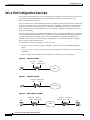
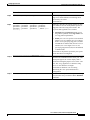
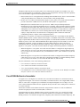
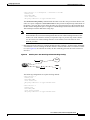
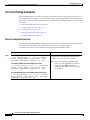
The illustrations below show examples of voice port usage.
•
In Figure 10, one voice port connects a telephone to the wide-area network (WAN) through the
router.
•
In Figure 11, one voice port connects to the PSTN and another to a telephone; the router acts like a
small PBX.
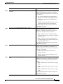
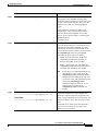
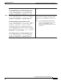
•
Figure 12 shows how two PBXs can be connected over a WAN to provide toll bypass.
Figure 10
Telephone to WAN
WAN
V
Figure 11
37754
Voice port
Serial or
1/0/0
Ethernet port
Telephone to PSTN
PSTN
V
PBX-to-PBX over a WAN
Voice port Serial or
1/0/0 Ethernet port
Serial or Voice port
Ethernet port 1/0/0
PBX
PBX
V
Cisco IOS Voice, Video, and Fax Configuration Guide
VC-36
WAN
V
37756
Figure 12
37755
Voice port Voice port
1/0/0
0/0/1
Configuring Voice Ports
Voice Port Configuration Overview
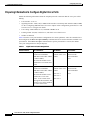
Cisco provides a variety of Cisco IOS commands for flexibility in programming voice ports to match the
physical attributes of the voice connections that are being made. Some of these connections are made
using analog means of transmission, while others use digital transmission. Table 4 shows the analog and
digital voice-port connection support of the router platforms discussed in this chapter.
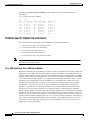
Table 4
Analog and Digital Voice-port Support on Cisco Routers and Access Servers
Platform
Analog
Digital
Cisco 803 and 804
Yes
No
Cisco 1750
Yes
No
Cisco 2600 series
Yes
Yes
Cisco 3600 series
Yes
Yes
Cisco MC3810
Yes
Yes
Cisco AS5300
No
Yes
Cisco AS5800
No
Yes
Cisco 7200 series
No
Yes
Cisco 7500 series
No
Yes
Telephony Signaling Interfaces
Voice ports on routers and access servers physically connect the router or access server to telephony
devices such as telephones, fax machines, PBXs, and PSTN central office (CO) switches. These devices
may use any of several types of signaling interfaces to generate information about on-hook status,
ringing, and line seizure.
The router’s voice-port hardware and software need to be configured to transmit and receive the same
type of signaling being used by the device with which they are interfacing so that calls can be exchanged
smoothly between the packet network and the circuit-switched network.
The signaling interfaces discussed in this chapter include foreign exchange office (FXO), foreign
exchange station (FXS), and receive and transmit (E&M), which are types of analog interfaces. Some
digital connections emulate FXO, FXS, and E&M interfaces, and they are discussed in the second half
of this chapter. It is important to know which signaling method the telephony side of the connection is
using, and to match the router configuration and voice interface hardware to that signaling method.
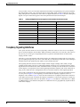
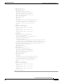
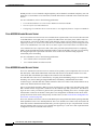
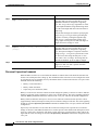
The next three illustrations show how the different signaling interfaces are associated with different uses
of voice ports. In Figure 13, FXS signaling is used for end-user telephony equipment, such as a
telephone or fax machine. Figure 14 shows an FXS connection to a telephone and an FXO connection
to the PSTN at the far side of a WAN; this might be a telephone at a local office going over a WAN to a
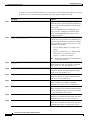
router at headquarters that connects to the PSTN. In Figure 15, two PBXs are connected across a WAN
by E&M interfaces. This illustrates the path over a WAN between two geographically separated offices
in the same company.
Cisco IOS Voice, Video, and Fax Configuration Guide
VC-37
Configuring Voice Ports
Voice Port Configuration Overview
FXS Signaling Interfaces
FXS
WAN
V
FXS
FXS and FXO Signaling Interfaces
Voice port Serial or
1/0/0 Ethernet port
FXS
Figure 15
V
Serial or Voice port
Ethernet port 1/0/0
WAN
V
V
FXO
PSTN
37758
Figure 14
Serial or Voice port
Ethernet port 1/0/0
37757
Voice port Serial or
1/0/0 Ethernet port
E&M Signaling Interfaces
Voice port Serial or
1/0/0 Ethernet port
Serial or Voice port
Ethernet port 1/0/0
PBX
PBX
E&M
V
WAN
V
E&M
37759
Figure 13
FXS and FXO Interfaces
An FXS interface connects the router or access server to end-user equipment such as telephones, fax
machines, or modems. The FXS interface supplies ring, voltage, and dial tone to the station and includes an
RJ-11 connector for basic telephone equipment, keysets, and PBXs.
An FXO interface is used for trunk, or tie line, connections to a PSTN CO or to a PBX that does not
support E&M signaling (when local telecommunications authority permits). This interface is of value
for off-premise station applications. A standard RJ-11 modular telephone cable connects the FXO voice
interface card to the PSTN or PBX through a telephone wall outlet.
FXO and FXS interfaces indicate on-hook or off-hook status and the seizure of telephone lines by one
of two access signaling methods: loop start or ground start. The type of access signaling is determined
by the type of service from the CO; standard home telephone lines use loop start, but business telephones
can order ground start lines instead.
Cisco IOS Voice, Video, and Fax Configuration Guide
VC-38
Configuring Voice Ports
Voice Port Configuration Overview
Loop-start is the more common of the access signaling techniques. When a handset is picked up (the
telephone goes off-hook), this action closes the circuit that draws current from the telephone company
CO and indicates a change in status, which signals the CO to provide dial tone. An incoming call is
signaled from the CO to the handset by sending a signal in a standard on/off pattern, which causes the
telephone to ring.
Loop-start has two disadvantages, however, that usually are not a problem on residential telephones but
that become significant with the higher call volume experienced on business telephones. Loop-start
signaling has no means of preventing two sides from seizing the same line simultaneously, a condition
known as glare. Also, loop start signaling does not provide switch-side disconnect supervision for FXO
calls. The telephony switch (the connection in the PSTN, another PBX, or key system) expects the
router’s FXO interface, which looks like a telephone to the switch, to hang up the calls it receives
through its FXO port. However, this function is not built into the router for received calls; it only
operates for calls originating from the FXO port.
Another access signaling method used by FXO and FXS interfaces to indicate on-hook or off-hook status
to the CO is ground start signaling. It works by using ground and current detectors that allow the network
to indicate off-hook or seizure of an incoming call independent of the ringing signal and allow for
positive recognition of connects and disconnects. For this reason, ground start signaling is typically used
on trunk lines between PBXs and in businesses where call volume on loop start lines can result in glare.
See the “Disconnect Supervision Commands” section on page 82 and “FXO Supervisory Disconnect
Tone Commands” section on page 85 for voice port commands that configure additional recognition of
disconnect signaling.
In most cases, the default voice port command values are sufficient to configure FXO and FXS voice
ports.
E&M Interfaces
Trunk circuits connect telephone switches to one another; they do not connect end-user equipment to the
network. The most common form of analog trunk circuit is the E&M interface, which uses special
signaling paths that are separate from the trunk’s audio path to convey information about the calls. The
signaling paths are known as the E-lead and the M-lead. The name E&M is thought to derive from the
phrase Ear and Mouth or rEceive and transMit although it could also come from Earth and Magnet. The
history of these names dates back to the days of telegraphy, when the CO side had a key that grounded
the E circuit, and the other side had a sounder with an electromagnet attached to a battery. Descriptions
such as Ear and Mouth were adopted to help field personnel determine the direction of a signal in a wire.
E&M connections from routers to telephone switches or to PBXs are preferable to FXS/FXO
connections because E&M provides better answer and disconnect supervision.
Like a serial port, an E&M interface has a data terminal equipment/data communications equipment
(DTE/DCE) type of reference. In the telecommunications world, the trunking side is similar to the DCE,
and is usually associated with CO functionality. The router acts as this side of the interface. The other
side is referred to as the signaling side, like a DTE, and is usually a device such as a PBX. Five distinct
physical configurations for the signaling part of the interface (Types I-V) use different methods to signal
on-hook/off-hook status, as shown in Table 5. Cisco voice implementation supports E&M Types I, II,
III, and V.
The physical E&M interface is an RJ-48 connector that connects to PBX trunk lines, which are classified
as either two-wire or four-wire. This refers to whether the audio path is full duplex on one pair of wires
(two-wire) or on two pair of wires (four-wire). A connection may be called a four-wire E&M circuit
although it actually has six to eight physical wires. It is an analog connection although an analog E&M
circuit may be emulated on a digital line. For more information on digital voice port configuration of
E&M signaling, see the “DS0 Groups on Digital T1/E1 Voice Ports” section on page 70.
Cisco IOS Voice, Video, and Fax Configuration Guide
VC-39
Configuring Voice Ports
Analog Voice Ports Configuration Task List
PBXs built by different manufacturers can indicate on-hook/off-hook status and telephone line seizure
on the E&M interface by using any of three types of access signaling that are as follows:
•
Immediate-start is the simplest method of E&M access signaling. The calling side seizes the line by
going off-hook on its E-lead and sends address information as dual-tone multifrequency (DTMF)
digits (or as dialed pulses on Cisco 2600 series routers and Cisco 3600 series routers) following a
short, fixed-length pause.
•
Wink-start is the most commonly used method for E&M access signaling, and is the default for
E&M voice ports. Wink-start was developed to minimize glare, a condition found in immediate-start
E&M, in which both ends attempt to seize a trunk at the same time. In wink-start, the calling side
seizes the line by going off-hook on its E-lead, then waits for a short temporary off-hook pulse, or
“wink,” from the other end on its M-lead before sending address information. The switch interprets
the pulse as an indication to proceed and then sends the dialed digits as DTMF or dialed pulses.
•
In delay-dial signaling, the calling station seizes the line by going off-hook on its E-lead. After a
timed interval, the calling side looks at the status of the called side. If the called side is on-hook, the
calling side starts sending information as DTMF digits; otherwise, the calling side waits until the
called side goes on-hook and then starts sending address information.
Table 5
E&M Wiring and Signaling Methods
M-Lead
E&M Type E-Lead Configuration Configuration
Signal Battery Lead
Configuration
Signal Ground Lead
Configuration
I
Output, relay to
ground
Input, referenced to
ground
—
—
II
Output, relay to SG
Input, referenced to
ground
Feed for M,
connected to –48V
Return for E,
galvanically isolated
from ground
III
Output, relay to
ground
Input, referenced to
ground
Connected to –48V
Connected to ground
V
Output, relay to
ground
Input, referenced to
–48V
—
—
Analog Voice Ports Configuration Task List
Analog voice port interfaces connect routers in packet-based networks to analog two-wire or four-wire
analog circuits in telephony networks. Two-wire circuits connect to analog telephone or fax devices, and
four-wire circuits connect to PBXs. Typically, connections to the PSTN CO are made with digital
interfaces.
This section describes how to configure analog voice ports and covers the following topics:
•
Configuring Codec Complexity for Analog Voice Ports on the Cisco MC3810 with
High-Performance Compression Modules, page 45
•
Configuring Basic Parameters on Analog FXO, FXS, or E&M Voice Ports, page 46
•
Configuring Analog Telephone Connections on Cisco 803 and 804 Routers, page 50
Cisco IOS Voice, Video, and Fax Configuration Guide
VC-40
Configuring Voice Ports
Analog Voice Ports Configuration Task List
Three other sections later in the chapter provide help with fine-tuning and troubleshooting:
•
Fine-Tuning Analog and Digital Voice Ports, page 78
•
Verifying Analog and Digital Voice-Port Configurations, page 97
•
Troubleshooting Analog and Digital Voice Port Configurations, page 108
Prerequisites for Configuring Analog Voice Ports
•
Obtain two- or four-wire line service from your service provider or from a PBX.
•
Complete your company’s dial plan.
•
Establish a working telephony network based on your company’s dial plan.
•
Install at least one other network module or WAN interface card to provide the connection to the
network LAN or WAN.
•
Establish a working IP and Frame Relay or ATM network. For more information about configuring
IP, refer to the Cisco IOS IP Configuration Guide, Release 12.2.
•
Install appropriate voice processing and voice interface hardware on the router. See the
“Configuring Platform-Specific Analog Voice Hardware” section on page 43.
Preparing to Configure Analog Voice Ports
Before configuring an analog voice port, assemble the following information about the telephony
connection that the voice port will be making. If connecting to a PBX, it is important to understand the
PBX’s wiring scheme and timing parameters. This information should be available from your PBX
vendor or the reference manuals that accompany your PBX.
•
Telephony signaling interface: FXO, FXS, or E&M
•
Locale code (usually the country) for call progress tones
•
If FXO, type of dialing: DTMF (touch-tone) or pulse
•
If FXO, type of start signal: loop-start or ground-start
•
If E&M, type: I, II, III, or V
•
If E&M, type of line: two-wire or four-wire
•
If E&M, type of start signal: wink, immediate, delay-dial
Table 6 should help you determine which hardware and configuration instructions are appropriate for
your situation. Table 7 on page 42 shows slot and port numbering, which differs for each of the
voice-enabled routers. More current information may be available in the release notes that accompany
the Cisco IOS software you are using.
Cisco IOS Voice, Video, and Fax Configuration Guide
VC-41
Configuring Voice Ports
Analog Voice Ports Configuration Task List
Table 6
Telephony
Signaling
Interface
Analog Voice Port Configurations
Router Platform
End user:
Cisco 803
telephone or Cisco 804
fax
FXO
“Configuring Analog Telephone
Connections on Cisco 803 and
804 Routers”
“Configuring Basic Parameters
on Analog FXO, FXS, or E&M
Voice Ports”
MC3810-AVM6
MC3810-APM-FXO
MC3810-AVM6
MC3810-APM-FXS
Cisco 1750
VIC-2E/M
Cisco 2600 series
Cisco 3600 series
Cisco MC3810
Table 7
Section Containing Voice Port
Configuration Instructions
Cisco 1750
VIC-2FXS
Cisco 2600 series
Cisco 3600 series
Cisco MC3810
E&M
—
Cisco 1750
VIC-2FXO, VIC-2FXO-EU
Cisco 2600 series
Cisco 3600 series
Cisco MC3810
FXS
Voice Hardware Required
MC3810-AVM6
MC3810-APM-EM
Analog Voice Slot/Port Designations
Router Platform
Voice Hardware
Chassis Slot
Numbers
Voice NM Slot Voice Port
Numbers
Numbers
Cisco 803, 804
Analog POTS
—
—
—
Cisco 1750
Analog VIC
0 to 1
—
0 to 1
Cisco 2600 series
Voice/fax network module
with two-port VIC
Varies, based
on router
1
0 to 1
Cisco 3600 series
Voice/fax network module
with two-port voice over
interface cards (VICs)
1
3620: 0 to 1
0 to 1
3640: 0 to 3
3660: 1 to 6
Cisco MC3810
Analog voice module (AVM)
Cisco IOS Voice, Video, and Fax Configuration Guide
VC-42
1
—
1 to 6
Configuring Voice Ports
Analog Voice Ports Configuration Task List
Configuring Platform-Specific Analog Voice Hardware
This section describes the general types of analog voice port hardware available for the router platforms
included in this chapter:
Note
•
Cisco 800 Series Routers, page 43
•
Cisco 1750 Modular Router, page 43
•
Cisco 2600 Series and Cisco 3600 Series Routers, page 44
•
Cisco MC3810 Multiservice Concentrator, page 44
For current information about supported hardware, see the release notes for the platform and
Cisco IOS release being used.
Cisco 800 Series Routers
Cisco 803 and Cisco 804 routers support data and voice applications. The data applications on these
routers are implemented through the ISDN port, and the voice applications are implemented with ISDN
Basic Rate Interface (BRI) through the telephone ports. If a Cisco 803 or 804 router is being used,
connect two devices, such as an analog touch-tone telephone, fax machine, or modem through two fixed
telephone ports, the gray PHONE 1 and PHONE 2 ports that have RJ-11 connectors. Each device is
connected to basic telephone services through the ISDN line.
For more information, refer to the Cisco 800 Series Routers Hardware Installation Guide.
Cisco 1750 Modular Router
The Cisco 1750 modular router provides Voice over IP (VoIP) functionality and can carry voice traffic
(for example, telephone calls and faxes) over an IP network. To make a voice connection, the router must
have a supported VIC installed. The Cisco 1750 router supports two slots for either WAN interface cards
(WICs) or VICs and supports one VIC-only slot. For analog connections, two-port VICs are available to
support FXO, FXS, and E&M signaling. VICs provide direct connections to telephone equipment
(analog phones, analog fax machines, key systems, or PBXs) or to a PSTN.
For more information, refer to the Cisco 1750 Voice-over-IP Quick Start Guide.
Cisco IOS Voice, Video, and Fax Configuration Guide
VC-43
Configuring Voice Ports
Analog Voice Ports Configuration Task List
Cisco 2600 Series and Cisco 3600 Series Routers
The Cisco 2600 and 3600 series routers are modular, multifunction platforms that combine dial access,
routing, local area network-to-local area network (LAN) services, and multiservice integration of voice,
video, and data in the same device.
Voice network modules installed in Cisco 2600 series or Cisco 3600 series routers convert telephone
voice signals into data packets that can be transmitted over an IP network. The voice network modules
have no connectors; VICs installed in the network modules provide connections to the telephone
equipment or network. VICs work with existing telephone and fax equipment and are compatible with
H.323 standards for audio and video conferencing.
The Cisco 2600 series router can house one network module. In the Cisco 3600 series, the Cisco 3620
router has slots for up to two network modules; the Cisco 3640 router has slots for up to four network
modules; and the Cisco 3660 router has slots for up to six network modules. (Typically, one of the slots
is used for LAN connectivity.)
For analog telephone connections, low-density voice/fax network modules that contain either one or two
VIC slots are installed in the network module slots. Each VIC is specific to a particular telephone
signaling interface (FXS, FXO, or E&M); therefore, the VIC determines the type of signaling on that
module.
For more information, refer to the following:
•
Cisco 2600 Series Hardware Installation Guide
•
Cisco 3600 Series Hardware Installation Guide
•
Cisco Network Module Hardware Installation Guide
Cisco MC3810 Multiservice Concentrator
To support analog voice circuits, a Cisco MC3810 multiservice concentrator must be equipped with an
AVM, which supports six analog voice ports. By installing specific signaling modules known as analog
personality modules (APMs), the analog voice ports may be equipped for the following signaling types
in various combinations: FXS, FXO, and E&M. For FXS, the analog voice ports use an RJ-11 connector
interface to connect to analog telephones or fax machines (two-wire) or to a key system (four-wire). For
FXO, the analog voice ports use an RJ-11 physical interface to connect to a CO trunk. For E&M
connections, the analog voice ports use an RJ-1CX physical interface to connect to an analog PBX
(two-wire or four-wire).
Optional high-performance voice compression modules (HCMs) can replace standard voice
compression modules (VCMs) to operate according to the voice compression coding algorithm (codec)
specified when the Cisco MC3810 concentrator is configured. The HCM2 provides four voice channels
at high codec complexity and eight channels at medium complexity. The HCM6 provides 12 voice
channels at high complexity and 24 channels at medium complexity. One or two HCMs can be installed
in a Cisco MC3810 multiservice concentrator, but an HCM may not be combined with a VCM in one
chassis.
For more information, refer to the Cisco MC3810 Multiservice Concentrator Hardware Installation
Guide.
Note
For current information about supported hardware, see the release notes for the platform and
Cisco IOS release being used.
Cisco IOS Voice, Video, and Fax Configuration Guide
VC-44
Configuring Voice Ports
Analog Voice Ports Configuration Task List
Configuring Codec Complexity for Analog Voice Ports on the Cisco MC3810
with High-Performance Compression Modules
The term codec stands for coder-decoder. A codec is a particular method of transforming analog voice
into a digital bit stream (and vice versa) and also refers to the type of compression used. Several different
codecs have been developed to perform these functions, and each one is known by the number of the
International Telecommunication Union-Telecommunication Standardization Sector (ITU-T) standard
in which it is defined. For example, two common codecs are the G.711 and the G.729 codecs. The various
codecs use different algorithms to encode analog voice into digital bit-streams and have different bit
rates, frame sizes, and coding delays associated with them. The codecs also differ in the amount of
perceived voice quality they achieve. Specialized hardware and software in the digital signal processors
(DSPs) perform codec transformation and compression functions, and different DSPs may offer different
selections of codecs.
Select the same type of codec as the one that is used at the other end of the call. For instance, if a call
was coded with a G.729 codec, it must be decoded with a G.729 codec. Codec choice is configured on
dial peers. For more information, see the “Configuring Dial Plans, Dial Peers, and Digit Manipulation”
chapter in this configuration guide.
Codec complexity refers to the amount of processing power that a codec compression technique
requires: some require more processing power than others. Codec complexity affects call density, which
is the number of calls that can take place on the DSP interfaces, which can be HCMs, port adapter DSP
farms, or voice cards, depending on the type of router (in this case, the Cisco MC3810 multiservice
concentrator). The greater the codec complexity, the fewer the calls that can be handled.
Codec complexity is either medium or high. The difference between medium- and high-complexity
codecs is the amount of CPU power necessary to process the algorithm and, therefore, the number of
voice channels that can be supported by a single DSP. All medium-complexity codecs can also be run in
high-complexity mode, but fewer (usually half as many) channels will be available per DSP.
For details on the number of calls that can be handled simultaneously using each of the codec standards,
refer to the entries for the codec and codec complexity commands in the Cisco IOS Voice, Video, and
Fax Command Reference.
On a Cisco MC3810 concentrator, only a single codec complexity setting is used, even when two HCMs
are installed. The value that is specified in this task affects the choice of codecs available when the codec
dial-peer configuration command is configured. See the “Configuring Dial Plans, Dial Peers, and Digit
Manipulation” chapter in this configuration guide.
Note
On the Cisco MC3810 with high-performance compression modules, check the DSP voice channel
activity with the show voice dsp command. If any DSP voice channels are in the busy state, the codec
complexity cannot be changed. When all the DSP channels are in the idle state, changes can be made
to the codec complexity selection.
Cisco IOS Voice, Video, and Fax Configuration Guide
VC-45
Configuring Voice Ports
Analog Voice Ports Configuration Task List
To configure codec complexity on the Cisco MC3810 multiservice concentrator using HCMs, use the
following commands beginning in privileged EXEC mode:
Step 1
Command
Purpose
Router# show voice dsp
Checks the DSP voice channel activity. If any DSP
voice channels are in the busy state, the codec
complexity cannot be changed.
When all the DSP channels are in the idle state,
continue to Step 2.
Step 2
Router# configure terminal
Enters global configuration mode.
Step 3
Router(config)# voice-card 0
Enters voice-card configuration mode and
specifies voice card 0.
Step 4
Router(config-voicecard)# codec complexity {high |
medium}
(For analog voice ports) Specifies codec
complexity based on the codec standard being
used. This setting restricts the codecs available in
dial peer configuration. All voice cards in a router
must use the same codec complexity setting.
The keywords are as follows:
•
high—Specifies two voice channels encoded
in any of the following formats:
G.711ulaw, G.711alaw, G.723.1(r5.3),
G.723.1 Annex A(r5.3), G.723.1(r6.3),
G.723.1 Annex A(r6.3), G.726(r16),
G.726(r24), G.726(r32), G.728, G.729, G.729
Annex B, and fax relay.
•
medium—(default) Specifies four voice
channels encoded in any of the following
formats: G.711ulaw, G.711alaw, G.726(r16),
G.726(r24), G.726(r32), G.729 Annex A,
G.729 Annex B with Annex A, and fax relay.
Note
If two HCMs are installed, this command
configures both HCMs at once.
Configuring Basic Parameters on Analog FXO, FXS, or E&M Voice Ports
This section describes commands for basic analog voice port configuration. All the data recommended
in the “Preparing to Configure Analog Voice Ports” section on page 41 should be gathered before
starting this procedure.
If configuring a Cisco MC3810 multiservice concentrator that has HCMs, codec complexity should also
be configured, following the steps in the “Configuring Codec Complexity for Analog Voice Ports on the
Cisco MC3810 with High-Performance Compression Modules” section on page 45.
Note
If you have a Cisco MC3810 multiservice concentrator or Cisco 3660 router, the compand-type
a-law command must be configured on the analog ports only. The Cisco 2660, 3620, and 3640 routers
do not require the configuration of th compand-type a-law command, however, if you request a list
of commands, the compand-type a-law command will display.
Cisco IOS Voice, Video, and Fax Configuration Guide
VC-46
Configuring Voice Ports
Analog Voice Ports Configuration Task List
In addition to the basic voice port parameters described in this section, there are commands that allow
voice port configurations to be fine tuned. In most cases, the default values for fine-tuning commands
are sufficient for establishing FXO and FXS voice port configurations. E&M voice ports are more likely
to require some configuration. If it is necessary to change some of the voice port values to improve voice
quality or to match parameters on proprietary PBXs to which you are connecting, use the commands in
the current section and also in the “Fine-Tuning Analog and Digital Voice Ports” section on page 78.
After the voice-port has been configured, make sure that the ports are operational by following the steps
described in the following sections:
•
Verifying Analog and Digital Voice-Port Configurations, page 97
•
Troubleshooting Analog and Digital Voice Port Configurations, page 108
For more information on these and other voice port commands, see the Cisco IOS Voice, Video, and Fax
Command Reference.
Note
The commands, keywords, and arguments that you are able to use may differ slightly from those
presented here, based on your platform, Cisco IOS release, and configuration. When in doubt, use
Cisco IOS command help (command ?) to determine the syntax choices that are available.
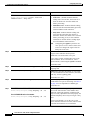
To configure basic analog voice port parameters on Cisco 1750, Cisco 2600 series, Cisco 3600 series,
and Cisco MC3810 routers, use the following commands beginning in global configuration mode:
Step 1
Command
Purpose
Cisco 1750 and MC3810
Enters voice-port configuration mode.
Router(config)# voice-port slot/port
The arguments are as follows:
Cisco 2600 and 3600 series
•
slot—Specifies the number of the router slot
where the voice network module is installed
(Cisco 2600 and Cisco 3600 series routers) or
the router slot number where the analog voice
module is installed (Cisco MC3810
multiservice concentrator).
•
port—Indicates the voice port. Valid entries
are 0 or 1.
•
subunit—Specifies the location of the VIC.
Router(config)# voice-port slot/subunit/port
Note
The slash must be entered between slot
and port.
Valid entries vary by router platform; see Table 7
on page 42 or enter the show voice port
summary command for available values.
Step 2
FXO or FXS
Router(config-voiceport)# signal {loop-start |
ground-start}
Selects the access signaling type to match that of
the telephony connection you are making. The
keywords are as follows:
•
loop-start—(default) Uses a closed circuit to
indicate off-hook status; used for residential
loops.
•
ground-start—Uses ground and current
detectors; preferred for PBXs and trunks.
Cisco IOS Voice, Video, and Fax Configuration Guide
VC-47
Configuring Voice Ports
Analog Voice Ports Configuration Task List
Command
Purpose
E&M
The keywords are as follows:
Router(config-voiceport)# signal {wink-start |
immediate-start | delay-dial}
•
wink-start—(default) Indicates that the
calling side seizes the line, then waits for a
short off-hook wink from the called side
before proceeding.
•
immediate-start—Indicates that the calling
side seizes the line and immediately proceeds;
used for E&M tie trunk interfaces.
•
delay-dial—Indicates that the calling side
seizes the line and waits, then checks to
determine whether the called side is on-hook
before proceeding; if not, it waits until the
called side is on-hook before sending digits.
Used for E&M tie trunk interfaces.
Note
Step 3
Router(config-voiceport)# cptone locale
Configuring the signal keyword for one
voice port on a Cisco 2600 or 3600 series
router VIC changes the signal value for
both ports on the VIC.
Selects the two-letter locale for the voice call
progress tones and other locale-specific
parameters to be used on this voice port.
Cisco routers comply with the ISO 3166 locale
name standards. To see valid choices, enter a
question mark (?) following the cptone command.
The default is us.
Step 4
Router(config-voiceport)# dial-type {dtmf | pulse}
(FXO only) Specifies the dialing method for
outgoing calls.
Step 5
Router(config-voiceport)# operation {2-wire | 4-wire}
(E&M only) Specifies the number of wires used
for voice transmission at this interface (the audio
path only, not the signaling path).
Step 6
Router(config-voiceport)# type {1 | 2 | 3 | 5}
The default is 2-wire.
(E&M only) Specifies the type of E&M interface
to which this voice port is connecting. See Table 5
on page 40 for an explanation of E&M types.
The default is 1.
Step 7
Cisco 1750 Router and 2600 and 3600 Series Routers
Router(config-voiceport)# ring frequency {25 | 50}
Cisco MC3810 Multiservice Concentrator
Router(config-voiceport)# ring frequency {20 | 30}
(FXS only) Selects the ring frequency, in hertz,
used on the FXS interface. This number must
match the connected telephony equipment and
may be country-dependent. If not set properly, the
attached telephony device may not ring or it may
buzz.
The keyword default is 25 on the Cisco 1750
router, 2600 and 3600 series routers; and 20 on the
Cisco MC3810 multiservice concentrator.
Cisco IOS Voice, Video, and Fax Configuration Guide
VC-48
Configuring Voice Ports
Analog Voice Ports Configuration Task List
Step 8
Command
Purpose
Router(config-voiceport)# ring number number
(FXO only) Specifies the maximum number of
rings to be detected before an incoming call is
answered by the router.
The default is 1.
Step 9
Router(config-voiceport)# ring cadence {[pattern01 |
pattern02 | pattern03 | pattern04 | pattern05 |
pattern06 | pattern07 | pattern08 | pattern09 |
pattern10 | pattern11 | pattern12] | [define pulse
interval]}
(FXS only) Specifies an existing pattern for ring,
or it defines a new one. Each pattern specifies a
ring-pulse time and a ring-interval time. The
keywords and arguments are as follows:
•
pattern01 through pattern12 name pre-set
ring cadence patterns. Enter ring cadence ? to
see ring pattern explanations.
•
define pulse interval specifies a user-defined
pattern: pulse is a number (one or two digits,
from 1 to 50) specifying ring pulse (on) time
in hundreds of milliseconds, and interval is a
number (one or two digits from 1 to 50)
specifying ring interval (off) time in hundreds
of milliseconds.
The default is the pattern specified by the cptone
locale that has been configured.
Step 10
Router(config-voiceport)# description string
Attaches a text string to the configuration that
describes the connection for this voice port. This
description appears in various displays and is
useful for tracking the purpose or use of the voice
port. The string argument is a character string
from 1 to 255 characters in length.
The default is that there is no text string
(describing the voice port) attached to the
configuration.
Step 11
Router(config-voiceport)# no shutdown
Activates the voice port. If a voice port is not being
used, shut the voice port down with the shutdown
command.
Cisco IOS Voice, Video, and Fax Configuration Guide
VC-49
Configuring Voice Ports
Analog Voice Ports Configuration Task List
Configuring Analog Telephone Connections on Cisco 803 and 804 Routers
Multiple devices (analog telephone, fax machine, or modem) can be connected to a Cisco 803 or 804
telephone port. The number of devices that can be connected depends on the ringer equivalent number
(REN) of each device that is to be connected. (The REN can usually be found on the bottom of a device.)
The REN of the router telephone port is 5, so if the REN of each device to be connected is 1, a maximum
of five devices can be connected to that particular telephone port.
These routers support touch-tone analog telephones only; they do not support rotary telephones.
To configure standard features for analog telephone connections on Cisco 803 and 804 routers, use the
following commands in global configuration mode:
Step 1
Command
Purpose
Router(config)# pots country country
Specifies the country to use for country-specific
default settings for physical characteristics. Enter
pots country ? for a list of supported countries and
the codes to enter.
A default country is not defined.
Step 2
Router(config)# pots line-type {type1 | type2 |
type3}
(Optional) Specifies the impedance of telephones,
fax machines, or modems connected to a Cisco 800
series router. The keywords are as follows:
•
type1—Specifies the resistance used for the
POTS connection, typically 600 ohms.
•
type2—Specifies the resistance used for the
POTS connection, typically 900 ohms.
•
type3—Specifies the resistance used for the
POTS connection, typically 300/400 ohms.
The default depends on the country chosen in the
pots country command.
Step 3
Router(config)# pots dialing-method {overlap |
enblock}
(Optional) Specifies how the router collects and
sends digits dialed on connected telephones, fax
machines, or modems. The keywords are as follows:
•
overlap—Tells the router to send each digit
dialed in a separate message.
•
enblock—Tells the router to collect all digits
dialed and to send the digits in one message.
The default depends on the country chosen in the
pots country command.
Cisco IOS Voice, Video, and Fax Configuration Guide
VC-50
Configuring Voice Ports
Analog Voice Ports Configuration Task List
Step 4
Command
Purpose
Router(config)# pots disconnect-supervision {osi |
reversal}
(Optional) Specifies how the router notifies the
connected telephones, fax machines, or modems
when the calling party has disconnect. The keywords
are as follows:
•
osi—(open switching interval) Specifies the
duration for which DC voltage applied between
tip and ring conductors of a telephone port is
removed.
•
reversal—Specifies the polarity reversal of the
tip and ring conductors of a telephone port.
The default depends on the country chosen in the
pots country command.
Step 5
Router(config)# pots encoding {alaw | ulaw}
(Optional) Specifies the pulse code modulation
(PCM) encoding scheme for telephones, fax
machines, or modems connected to a Cisco 800
series router. The keywords are as follows:
•
alaw—Specifies the ITU-T PCM encoding
scheme used to represent analog voice samples
as digital values.
•
ulaw—Specifies the North American PCM
encoding scheme used to represent analog voice
samples as digital values.
The default depends on the country chosen in the
pots country command.
Step 6
Step 7
Router(config)# pots tone-source {local | remote}
Router(config)# pots ringing-freq {20Hz | 25Hz |
50Hz}
(Optional) Specifies the source of dial, ringback,
and busy tones for telephones, fax machines, or
modems connected to a Cisco 800 series router. The
keywords are as follows:
•
local—(default) Specifies that the router
supplies the tones.
•
remote—Specifies that the telephone switch
supplies the tones.
(Optional) Specifies the frequency at which
telephones, fax machines, or modems connected to a
Cisco 800 series router ring. The keywords are as
follows:
•
20Hz—Indicates that connected devices ring at
20 Hz.
•
25Hz—Indicates that connected devices ring at
25 Hz.
•
50Hz—Indicates that connected devices ring at
50 Hz.
The default depends on the country chosen in the
pots country command.
Cisco IOS Voice, Video, and Fax Configuration Guide
VC-51
Configuring Voice Ports
Analog Voice Ports Configuration Task List
Step 8
Command
Purpose
Router(config)# pots disconnect-time interval
(Optional) Specifies the interval at which the
disconnect method is applied if connected
telephones, fax machines, or modems fail to detect
that a calling party has disconnected. The interval
argument is the number of milliseconds of the
interval and ranges from 50 to 2000.
The default depends on the country chosen in the
pots country command.
Step 9
Router(config)# pots silence-time seconds
(Optional) Specifies the interval of silence after a
calling party disconnects. The seconds argument is
the number of seconds of the interval and ranges
from 0 to 10.
The default depends on the country chosen in the
pots country command.
Step 10
Router(config)# pots distinctive-ring-guard-time
milliseconds
(Optional) Specifies the delay after which a
telephone port can be rung after a previous call is
disconnected. The milliseconds argument is the
number of milliseconds of the delay and ranges from
0 to 1000.
The default depends on the country chosen in the
pots country command.
Verifying Analog Telephone Connections on Cisco 803 and 804 Routers
After configuring analog telephone connections, perform the following steps to verify proper operation:
Step 1
Pick up the handset of an attached telephony device and check for a dial tone.
Step 2
Review the configuration using the show pots status command, which displays settings of physical
characteristics and other information on telephone interfaces.
Router# show pots status
POTS Global Configuration:
Country: United States
Dialing Method: Overlap, Tone Source: Remote, CallerId Support: YES
Line Type: 600 ohm, PCM Encoding: u-law, Disc Type: OSI,
Ringing Frequency: 20Hz, Distinctive Ring Guard timer: 0 msec
Disconnect timer: 1000 msec, Disconnect Silence timer: 5 sec
TX Gain: 6dB, RX Loss: -6dB,
Filter Mask: 6F
Adaptive Cntrl Mask: 0
POTS PORT: 1
Hook Switch Finite State Machine:
State: On Hook, Event: 0
Hook Switch Register: 10, Suspend Poll: 0
CODEC Finite State Machine
State: Idle, Event: 0
Connection: None, Call Type: Two Party, Direction: Rx only
Line Type: 600 ohm, PCM Encoding: u-law, Disc Type: OSI,
Ringing Frequency: 20Hz, Distinctive Ring Guard timer: 0 msec
Disconnect timer: 1000 msec, Disconnect Silence timer: 5 sec
TX Gain: 6dB, RX Loss: -6dB,
Cisco IOS Voice, Video, and Fax Configuration Guide
VC-52
Configuring Voice Ports
Analog Voice Ports Configuration Task List
Filter Mask: 6F
Adaptive Cntrl Mask: 0
CODEC Registers:
SPI Addr: 2, DSLAC Revision: 4
SLIC Cmd: 0D, TX TS: 00, RX TS: 00
Op Fn: 6F, Op Fn2: 00, Op Cond: 00
AISN: 6D, ELT: B5, EPG: 32 52 00 00
SLIC Pin Direction: 1F
CODEC Coefficients:
GX: A0 00
GR: 3A A1
Z: EA 23 2A 35 A5 9F C2 AD 3A AE 22 46 C2 F0
B: 29 FA 8F 2A CB A9 23 92 2B 49 F5 37 1D 01
X: AB 40 3B 9F A8 7E 22 97 36 A6 2A AE
R: 01 11 01 90 01 90 01 90 01 90 01 90
GZ: 60
ADAPT B: 91 B2 8F 62 31
CSM Finite State Machine:
Call 0 - State: idle, Call Id: 0x0
Active: no
Call 1 - State: idle, Call Id: 0x0
Active: no
Call 2 - State: idle, Call Id: 0x0
Active: no
POTS PORT: 2
Hook Switch Finite State Machine:
State: On Hook, Event: 0
Hook Switch Register: 20, Suspend Poll: 0
CODEC Finite State Machine:
State: Idle, Event: 0
Connection: None, Call Type: Two Party, Direction: Rx only
Line Type: 600 ohm, PCM Encoding: u-law, Disc Type: OSI,
Ringing Frequency: 20Hz, Distinctive Ring Guard timer: 0 mse
Disconnect timer: 1000msec,Disconnect Silence timer: 5 sec
TX Gain: 6dB, RX Loss: -6dB,
Filter Mask: 6F
Adaptive Cntrl Mask: 0
CODEC Registers:
SPI Addr: 3, DSLAC Revision: 4
SLIC Cmd: 0D, TX TS: 00, RX TS: 00
Op Fn: 6F, Op Fn2: 00, Op Cond: 00
AISN: 6D, ELT: B5, EPG: 32 52 00 00
SLIC Pin Direction: 1F
CODEC Coefficients:
GX: A0 00
GR: 3A A1
Z: EA 23 2A 35 A5 9F C2 AD 3A AE 22 46 C2 F0
B: 29 FA 8F 2A CB A9 23 92 2B 49 F5 37 1D 01
X: AB 40 3B 9F A8 7E 22 97 36 A6 2A AE
R: 01 11 01 90 01 90 01 90 01 90 01 90
GZ: 60
ADAPT B: 91 B2 8F 62 31
CSM Finite State Machine:
Call 0 - State: idle, Call Id: 0x0
Active: no
Call 1 - State: idle, Call Id: 0x0
Active: no
Call 2 - State: idle, Call Id: 0x0
Active: no
Time Slot Control: 0
Cisco IOS Voice, Video, and Fax Configuration Guide
VC-53
Configuring Voice Ports
Configuring Digital Voice Ports
Troubleshooting Tip for Cisco 803 and 804 Routers
Check to ensure that all cables are securely connected.
Configuring Digital Voice Ports
The digital voice port commands discussed in this section configure channelized T1 or E1 connections;
for information on ISDN connections, see “Configuring ISDN Interfaces for Voice” in this configuration
guide.
The T1 or E1 lines that connect a telephony network to the digital voice ports on a router or access server
contain channels for voice calls; a T1 line contains 24 full-duplex channels or timeslots, and an E1 line
contains 30. The signal on each channel is transmitted at 64 kbps, a standard known as digital signal 0
(DS0); the channels are known as DS0 channels. The ds0-group command creates a logical voice port
(a DS0 group) from some or all of the DS0 channels, which allows you to address those channels easily,
as a group, in voice-port configuration commands.
Digital voice ports are found at the intersection of a packet voice network and a digital, circuit-switched
telephone network. The digital voice port interfaces that connect the router or access server to T1 or E1 lines
pass voice data and signaling between the packet network and the circuit-switched network.
Signaling is the exchange of information about calls and connections between two ends of a
communication path. For instance, signaling communicates to the call’s end points whether a line is idle
or busy, whether a device is on-hook or off-hook, and whether a connection is being attempted. An end
point can be a CO switch, a PBX, a telephony device such as a telephone or fax machine, or a
voice-equipped router acting as a gateway. There are two aspects to consider about signaling on digital
lines: one aspect is the actual information about line and device states that is transmitted, and the second
aspect is the method used to transmit the information on the digital lines.
The actual information about line and device states is communicated over digital lines using signaling
methods that emulate the methods used in analog circuit-switched networks: FXS, FXO, and E&M.
The method used to transmit the information describes the way that the emulated analog signaling is
transmitted over digital lines, which may be common-channel signaling (CCS) or channel-associated
signaling (CAS). CCS sends signaling information down a dedicated channel and CAS takes place
within the voice channel itself. This chapter describes CAS signaling, which is sometimes called
robbed-bit signaling because user bandwidth is robbed by the network for signaling. A bit is taken from
every sixth frame of voice data to communicate on- or off-hook status, wink, ground start, dialed digits,
and other information about the call.
In addition to setting up and tearing down calls, CAS provides the receipt and capture of dialed number
identification (DNIS) and automatic number identification (ANI) information, which are used to support
authentication and other functions. The main disadvantage of CAS signaling is its use of user bandwidth
to perform these signaling functions.
For signaling to pass between the packet network and the circuit-switched network, both networks must
use the same type of signaling. The voice ports on Cisco routers and access servers can be configured to
match the signaling of most COs and PBXs, as explained in this chapter.
This section discusses the following topics:
•
Prerequisites for Configuring Digital Voice Ports, page 55
•
Preparing Information to Configure Digital Voice Ports, page 56
•
Platform-Specific Digital Voice Hardware, page 58
•
Configuring Basic Parameters on Digital T1/E1 Voice Ports, page 61
Cisco IOS Voice, Video, and Fax Configuration Guide
VC-54
Configuring Voice Ports
Configuring Digital Voice Ports
Prerequisites for Configuring Digital Voice Ports
Digital T1 or E1 packet voice capability requires specific service, software, and hardware:
•
Obtain T1 or E1 service from the service provider or from your PBX.
•
Create your company’s dial plan.
•
Establish a working telephony network based on your company’s dial plan.
•
Establish a connection to the network LAN or WAN.
•
Set up a working IP and Frame Relay or ATM network. For more information about configuring IP,
refer to the Cisco IOS IP Configuration Guide, Release 12.2.
•
Install appropriate voice processing and voice interface hardware on the router. See the
“Platform-Specific Digital Voice Hardware” section on page 58.
•
(Cisco 2600 and 3600 series routers) For digital T1 packet voice trunk network modules, install
Cisco IOS Release 12.0(5)XK, 12.0(7)T, 12.2(1), or a later release. The minimum DRAM memory
requirements are as follows:
– 32 MB, with one or two T1 lines
– 48 MB, with three or four T1 lines
– 64 MB, with five to ten T1 lines
– 128 MB, with more than ten T1 lines
The memory required for high-volume applications may be greater than that listed. Support for
digital T1 packet voice trunk network modules is included in Plus feature sets. The IP Plus feature
set requires 8 MB of Flash memory; other Plus feature sets require 16 MB.
•
(Cisco 2600 and 3600 series routers) For digital E1 packet voice trunk network modules, install
Cisco IOS Release 12.1(2)T, 12.2(1), or a later release. The minimum DRAM memory requirements
are:
– 48 MB, with one or two E1s
– 64 MB, with three to eight E1s
– 128 MB, with 9 to 12 E1s
For high-volume applications, the memory required may be greater than these minimum values.
Support for digital E1 packet voice trunk network modules is included in Plus feature sets. The IP
Plus feature set requires 16 MB of Flash memory.
•
(Cisco MC3810 concentrators) HCMs require Cisco IOS Release 12.0(7)XK or 12.1(2)T, 12.2(1),
or a later release.
•
(Cisco 7200 and 7500 series routers) For digital T1/E1 voice port adapters, install Cisco IOS
Release 12.0(5)XE, 12.0(7)T, 12.2(1), or a later release. The minimum DRAM memory requirement
to support T1/E1 high-capacity digital voice port adapters is 64 MB.
The memory required for high-volume applications may be greater than that listed. Support for T1/E1
high-capacity digital voice port adapters is included in Plus feature sets. The IP Plus feature set requires
16 MB of Flash memory.
Cisco IOS Voice, Video, and Fax Configuration Guide
VC-55
Configuring Voice Ports
Configuring Digital Voice Ports
Preparing Information to Configure Digital Voice Ports
Gather the following information about the telephony network connection that the voice port will be
making:
•
Line interface: T1 or E1
•
Signaling interface: FXO, FXS, or E&M. If the interfaces are Primary Rate Interface (PRI) or BRI,
see the “Configuring ISDN Interfaces for Voice” chapter in this configuration guide and Cisco IOS
Terminal Services Configuration Guide.
•
Line coding: AMI or B8ZS for T1, and AMI or HDB3 for E1
•
Framing format: SF (D4) or ESF for T1, and CRC4 or no-CRC4 for E1
•
Number of channels
Table 8 describes voice-port hardware configurations for various platforms. After the controllers have
been configured, the show voice port summary command can also be used to determine available voice
port numbers. If the show voice port command and a specific port number is entered, the default
voice-port configuration for that port displays.
Table 8
Digital Voice Slot/Port Designations
Router Platform
Voice Hardware
Slot Number
Port Number
Cisco 2600 series
Digital T1/E1 Packet Voice
Trunk Network Module
(NM-HDV with VWIC-1MFT
or VWIC-2MFT)
slot is the router
location of the voice
module.
port is the VWIC
location in the
network module.
1
0 to 1
slot is the router
location of the voice
module.
port is the VWIC
location in the
network module.
One network module can be
installed in a Cisco 2600 series
router.
Cisco 3600 series
Digital T1/E1 Packet Voice
Trunk Network Module
(NM-HDV with VWIC-1MFT
or VWIC-2MFT)
3620: 0 to 1
One network module can be
3640: 0 to 3
installed in a Cisco 3620
3660: 0 to 5
router. A Cisco 3640 router
can support three modules, and
as many as six can be installed
in a Cisco 3660 router.
Cisco IOS Voice, Video, and Fax Configuration Guide
VC-56
0 to 1
Configuring Voice Ports
Configuring Digital Voice Ports
Table 8
Digital Voice Slot/Port Designations (continued)
Router Platform
Cisco MC3810
Voice Hardware
•
Digital voice module
(DVM)
•
Voice compression
module (VCM3 or
VCM6)
Slot Number
Port Number
1
—
or
•
High-compression
module (HCM2 or
HCM6)
VCM3 and VCM6 do not
support codec complexity
options.
Cisco AS5300
Cisco AS5800
Cisco 7200 series
One Octal T1/E1 feature card —
(eight ports) or one Quad
T1/E1 feature card (four ports)
and one or two VFCs for voice
and fax features.
controller is :
Up to four 12-port T1/E1 trunk shelf is 1
cards and up to eight VFCs
slot is 0 to 5
0 to 11
Octal: 0 to 7
Quad: 0 to 3
Two-port T1/E1 enhanced Port adapter slot:
Interface port: 0 to 1
digital voice port adapters from 1 to 4, or from 1
to 6
• PA-VXC (high-capacity)
•
•
PA-VXB (moderate
capacity)
Port adapter slot 0 is reserved
for the Fast Ethernet port on
the I/O controller (if present).
Cisco 7500 series
PA-VXB and PA-VXC on a
VIP2 or VIP4 in Cisco 7500
series routers
If the VIP is inserted in
interface processor slot 3 and
port adapter slot 0, then the
addresses of the PA-VXB or
PA-VXC are 3/0/0 or 3/0/1
(interface processor slot 3,
port adapter slot 0, and
interfaces 0 and 1).
Interface processor
Port adapter slot:
slot: 0 to 12 (depends always 0 or 1
on the number of slots Interface port: 0 or 1
in the router)
Cisco IOS Voice, Video, and Fax Configuration Guide
VC-57
Configuring Voice Ports
Configuring Digital Voice Ports
The following is show voice port summary sample output for a Cisco MC3810 multiservice
concentrator:
Router# show voice port summary
IN
PORT
======
0:17
0:18
0:19
0:20
0:21
0:22
0:23
OUT
CH SIG-TYPE
== ==========
18 fxo-ls
19 fxo-ls
20 fxo-ls
21 fxo-ls
22 fxo-ls
23 fxo-ls
24 e&m-imd
ADMIN
=====
down
up
up
up
up
up
up
OPER
====
down
dorm
dorm
dorm
dorm
dorm
dorm
STATUS
========
idle
idle
idle
idle
idle
idle
idle
STATUS
========
on-hook
on-hook
on-hook
on-hook
on-hook
on-hook
idle
EC
==
y
y
y
y
y
y
y
Platform-Specific Digital Voice Hardware
This section briefly describes digital voice hardware on the following platforms:
Note
•
Cisco 2600 series and Cisco 3600 series routers
•
Cisco MC3810 multiservice concentrator
•
Cisco AS5300 universal access server
•
Cisco AS5800 universal access server
•
Cisco 7200 series and Cisco 7500 series routers
For current information about supported hardware, see the release notes for the platform and
Cisco IOS release you are using.
Cisco 2600 Series and Cisco 3600 Series Routers
Digital voice hardware on Cisco 2600 series and Cisco 3600 series modular access routers includes the
high-density voice (HDV) network module and the multiflex trunk (MFT) voice/WAN interface card
(VWIC). When an HDV is used in conjunction with an MFT and packet voice DSP modules (PVDMs),
the HDV module is also called a digital packet voice trunk network module. The digital T1 or E1 packet
voice trunk network module supports T1 or E1 applications, including fractional use. The T1 version
integrates a fully managed data service unit/channel service unit (DSU/CSU), and the E1 version
includes a fully managed DSU. The digital T1 or E1 packet voice trunk network module provides
per-channel T1 or E1 data rates of 64 or 56 kbps for WAN services (Frame Relay or leased line).
Digital T1 or E1 packet voice trunk network modules for Cisco 2600 and 3600 series routers allow
enterprises or service providers, using the voice-equipped routers as customer premise equipment
(CPE), to deploy digital voice and fax relay. These network modules receive constant bit-rate telephony
information over T1 or E1 interfaces and convert that information to a compressed format so that it can
be sent over a packet network. The digital T1 or E1 packet voice trunk network modules can connect
either to a PBX (or similar telephony device) or to a CO to provide PSTN connectivity. One digital T1
or E1 packet voice trunk network module can be installed in a Cisco 2600 series router or in a Cisco
3620 router. A Cisco 3640 router can support three network modules, and a Cisco 3660 router can
support up to six network modules.
Cisco IOS Voice, Video, and Fax Configuration Guide
VC-58
Configuring Voice Ports
Configuring Digital Voice Ports
The MFT VWICs that are used in the packet voice trunk network modules are available in one- and
two-port configurations for T1 and for E1, and in two-port configurations with drop-and-insert capability
for T1 and E1. MFTs support the following kinds of traffic:
•
Data. As WICs for T1 or E1 applications, including fractional data line use, the T1 version includes
a fully managed DSU/CSU, and the E1 version includes a fully managed DSU.
•
Packet voice. As VWICs included with the digital T1 or E1 packet voice trunk network module to
provide connections to PBXs and COs, the MFTs enable packet voice applications.
•
Multiplexed voice and data. Some two-port T1 or E1 VWICs can provide drop-and-insert
multiplexing services with integrated DSU/CSUs. For example, when used with a digital T1 packet
voice trunk network module, drop-and-insert allows 64-kbps DS0 channels to be taken from one T1
and digitally cross-connected to 64-kbps DS0 channels on another T1. Drop and insert, sometimes
called TDM cross-connect, uses circuit switching rather than the DSPs that VoIP technology
employs. (Drop-and-insert is described in the “Configuring Trunk Connections and Trunk
Conditioning Features” chapter in this configuration guide.)
The digital T1 or E1 packet voice trunk network module contains five 72-pin Single In-line Memory
Module (SIMM) sockets or banks, numbered 0 through 4, for PVDMs. Each socket can be filled with a
single 72-pin PVDM, and there must be at least one packet voice data module (PVDM-12) in the network
module to process voice calls. Each PVDM holds three digital signal processors (DSPs), so with five
PVDM slots populated, a total of 15 DSPs are provided. High-complexity codecs support two
simultaneous calls on each DSP, and medium-complexity codecs support four calls on each DSP. A
digital T1 or E1 packet voice trunk network module can support the following numbers of channels:
•
When the digital T1 or E1 packet voice trunk network module is configured for high-complexity
codec mode, up to six voice or fax calls can be completed per PVDM-12, using the following codecs:
G.711, G.726, G.729, G729 Annex A (E1), G.729 Annex B, G.723.1, G723.1 Annex A (T1), G.728,
and fax relay.
•
When the digital T1 or E1 packet voice trunk network module is configured for medium-complexity
codec mode, up to 12 voice or fax calls can be completed per PVDM-12, using the following codecs:
G.711, G.726, G.729 Annex A, G.729 Annex B with Annex A, and fax relay.
For more information, refer to the following publications:
•
Cisco 2600 Series Hardware Installation Guide
•
Cisco 3600 Series Hardware Installation Guide
•
Cisco Network Module Hardware Installation Guide
•
Cisco IOS Release 12.0(7)T online document Configuring 1- and 2-Port T1/E1 Multiflex Voice/WAN
Interface Cards on Cisco 2600 and 3600 Series Routers
Cisco MC3810 Multiservice Concentrator
To support a T1 or E1 digital voice interface, the Cisco MC3810 multiservice concentrator must be
equipped with a digital voice interface card (DVM). The DVM interfaces with a digital PBX, channel
bank, or video codec. It supports up to 24 channels of compressed digital voice at 8 kbps, or it can
cross-connect channelized data from user equipment directly onto the router’s trunk port for connection
to a carrier network.
The DVM is available with a balanced interface using an RJ-48 connector or with an unbalanced
interface using Bayonet-Neill-Concelman (BNC) connectors.
Optional HCMs can replace standard VCMs to operate according to the voice compression coding
algorithm (codec) specified when the Cisco MC3810 multiservice concentrator is configured. The
HCM2 provides 4 voice channels at high codec complexity and 8 channels at medium complexity. The
Cisco IOS Voice, Video, and Fax Configuration Guide
VC-59
Configuring Voice Ports
Configuring Digital Voice Ports
HCM6 provides 12 voice channels at high complexity and 24 channels at medium complexity. You can
install one or two HCMs in a Cisco MC3810, but an HCM can not be combined with a VCM in the same
chassis.
For more information, refer to the following publications:
•
Cisco MC3810 Multiservice Concentrator Hardware Installation Guide
•
Overview of the Cisco MC3810 Series
•
Configuring Cisco MC3810 Series Concentrators to Use High-Performance Compression Modules
Cisco AS5300 Universal Access Server
The Cisco AS5300 Universal Access Server includes three expansion slots. One slot is for either an Octal
T1/E1/PRI feature card (eight ports) or a Quad T1/E1/PRI feature card (four ports), and the other two
can be used for voice/fax or modem feature cards. Because a single voice/fax feature card (VFC) can
support up to 48 (T1) or 60 (E1) voice calls, the Cisco AS5300/Voice Gateway system can support a total
of 96 or 120 simultaneous voice calls. The use of VFCs requires Cisco IOS release 12.0.2XH or later.
Cisco AS5300 VFCs are coprocessor cards, each with a powerful reduced instruction set computing
(RISC) engine and dedicated, high-performance DSPs to ensure predictable, real-time voice processing.
The design couples this coprocessor with direct access to the Cisco AS5300 routing engine for
streamlined packet forwarding.
For more information, refer to the following publications:
•
Cisco AS5300 Chassis Installation Guide
•
Cisco AS5300 Module Installation Guide
Cisco AS5800 Universal Access Server
The Cisco AS5800 Universal Access Server consists of two primary system components: the Cisco 5814
dial shelf (DS), which holds channelized trunk cards and connects to the PSTN, and the Cisco 7206
router shelf (RS), which holds port adapters and connects to the IP backbone.
The dial shelf acts as the access concentrator by accepting and consolidating all types of remote traffic,
including voice, dial-in analog and digital ISDN data, and industry-standard WAN and remote
connection types. The dial shelf also contains controller cards voice feature cards, modem feature cards,
trunk cards, and dial shelf interconnect cards.
One or two dial shelf controllers (DSCs) provide clock and power control to the dial shelf cards. Each
DSC contains a block of logic that is referred to as the common logic and system clocks. This block of
logic can use a variety of sources to generate the system timing, including an E1 or T1/T3 input signal
from the BNC connector on the DSC's front panel. The configuration commands for the master clock
specify the various clock sources and a priority for each source (see the “Clock Sources on Digital T1/E1
Voice Ports” section on page 66).
The Cisco AS5800 voice feature card is a multi-DSP coprocessing board and software package that adds
VoIP capabilities to the Cisco AS5800 platform. The Cisco AS5800 voice feature card, when used with
other cards such as LAN/WAN and modem cards, provides a gateway for up to 192 packetized voice/fax
calls and 360 data calls per card. A Cisco AS5800 can support up to 1,344 voice calls in split-dial-shelf
configuration with two 7206VXR router shelves.
Cisco IOS Voice, Video, and Fax Configuration Guide
VC-60
Configuring Voice Ports
Configuring Digital Voice Ports
For more information, refer to the following publications:
•
Cisco AS5800 Universal Access Server Operation, Administration, Maintenance, and Provisioning
Guide
•
Cisco AS5800 Access Server Hardware Installation Guide
Cisco 7200 and Cisco 7500 Series Routers
Cisco 7200 and Cisco 7500 series routers support multimedia routing and bridging with a wide variety
of protocols and media types. The Cisco 7000 family versatile interface processor (VIP) is based on a
RISC engine optimized for I/O functions. To this engine are attached one or two port adapters or
daughter boards, which provide the media-specific interfaces to the network. The network interfaces
provide connections between the routers’ peripheral component interconnect (PCI) buses and external
networks. Port adapters can be placed in any available port adapter slot, in any desired combination.
T1/E1 high-capacity digital voice port adapters for Cisco 7200 and Cisco 7500 series routers allow
enterprises or service providers, using the equipped routers as customer premise equipment, to deploy
digital voice and fax relay. These port adapters receive constant bit-rate telephony information over
T1/E1 interfaces and can convert that information to a compressed format for transmission as voice over
IP (VoIP). Two types of digital voice port adapters are supported on Cisco 7200 and Cisco 7500 series
routers: two-port high-capacity (up to 48 or 120 channels of compressed voice, depending on codec
choice), and two-port moderate capacity (up to 24 or 48 channels of compressed voice). These
single-width port adapters incorporate two universal ports configurable for either T1 or E1 connection,
for use with high-performance digital signal processors (DSPs). Integrated CSU/DSUs, echo
cancellation, and DS0 drop-and-insert functionality eliminate the need for external line termination
devices and multiplexers.
For more information, refer to the following publications:
Note
•
Cisco 7200 VXR Installation and Configuration Guide
•
Cisco 7500 Series Installation and Configuration Guide
•
Two-Port T1/E1 Moderate-Capacity and High-Capacity Digital Voice Port Adapter Installation and
Configuration
For current information about supported hardware, see the release notes for the platform and
Cisco IOS release being used.
Configuring Basic Parameters on Digital T1/E1 Voice Ports
This section describes commands for basic digital voice port configuration. Make sure you have all the
data recommended in the “Preparing Information to Configure Digital Voice Ports” section on page 56
before starting this procedure.
Cisco IOS Voice, Video, and Fax Configuration Guide
VC-61
Configuring Voice Ports
Configuring Digital Voice Ports
The basic steps for configuring digital voice ports are described in the next three sections. They are
grouped by the configuration mode from which they are executed, as follows:
•
Configuring Codec Complexity for Digital T1/E1 Voice Ports, page 62
Codec complexity refers to the amount of processing power assigned to codec processing on a voice
port. On most router platforms that support codec complexity, codec complexity is selected in voice
card configuration mode, although it is selected in DSP interface mode on the Cisco 7200 and
7500 series. The value configured for codec complexity establishes the choice of codecs that are
available on the dial peers. See the Configuring Dial Plans, Dial Peers, and Digit Manipulation
chapter in this configuration guide for more information about configuring dial peers.
•
Configuring Controller Settings for Digital T1/E1 Voice Ports, page 65
Specific line characteristics must be configured to match those of the PSTN line that is being
connected to the voice port. These are typically configured in controller configuration mode.
•
Configuring Basic Voice Port Parameters for Digital T1/E1 Voice Ports, page 76
Voice port configuration mode allows many of the basic voice call attributes to be configured to
match those of the PSTN or PBX connection being made on this voice port.
In addition to the basic voice port parameters, there are additional commands that allow for the finetuning of the voice port configurations or for configuration of optional features. In most cases, the default
values for these commands are sufficient for establishing voice port configurations. If it is necessary to
change some of these parameters to improve voice quality or to match parameters in proprietary PBXs
to which you are connecting, use the commands in the “Fine-Tuning Analog and Digital Voice Ports”
section on page 78.
After voice port configuration, make sure the ports are operational by following the steps described in
these sections:
•
Verifying Analog and Digital Voice-Port Configurations, page 97
•
Troubleshooting Analog and Digital Voice Port Configurations, page 108
For more information on voice port commands, refer to the Cisco IOS Voice, Video, and Fax Command
Reference.
Configuring Codec Complexity for Digital T1/E1 Voice Ports
On the Cisco 2600, 3600, 7200, and 7500 routers, codec complexity can be configured separately for
each T1/E1 digital packet voice trunk network module or port adapter. On a Cisco MC3810 multiservice
concentrator, only a single codec complexity setting is used, even when two HCMs are installed. The
value specified in this task affects the choice of codecs available when the codec dial-peer configuration
command is configured.
For details on the number of calls that can be handled simultaneously using each of the codec standards,
refer to the entries for codec and codec complexity in the Cisco IOS Voice, Video, and Fax Command
Reference and to platform-specific product literature.
For more information on codec complexity, see the “Configuring Codec Complexity for Analog Voice
Ports on the Cisco MC3810 with High-Performance Compression Modules” section on page 45.
Two configuration task tables are shown below: one for the Cisco 2600 and 3600 series routers and the
Cisco MC3810 concentrator, which use voice card configuration mode, and the second for the
Cisco 7200 and 7500 series routers, which use DSP interface configuration mode.
Cisco IOS Voice, Video, and Fax Configuration Guide
VC-62
Configuring Voice Ports
Configuring Digital Voice Ports
Cisco 2600 and 3600 Series and Cisco MC3810
This procedure applies to voice ports on digital packet voice trunk network modules on
Cisco 2600 series and Cisco 3600 series routers, and to voice ports on HCMs on Cisco MC3810
multiservice concentrators.
Note
On Cisco 2600 and 3600 series routers with digital T1/E1 packet voice trunk network modules, codec
complexity cannot be configured if DS0 groups are configured. Use the no ds0-group command to
remove DS0 groups before configuring codec complexity.
Note
On the Cisco MC3810 multiservice concentrator with high compression modules, check the DSP
voice channel activity with the show voice dsp command. If any DSP voice channels are in the busy
state, you cannot change the codec complexity. When all of the DSP channels are in the idle state,
you can make changes to the codec complexity selection.
To configure codec complexity, use the following commands beginning in privileged EXEC mode:
Step 1
Command
Purpose
Router# show voice dsp
Checks the DSP voice channel activity. If any DSP voice
channels are in the busy state, codec complexity cannot be
changed.
When all of the DSP channels are in the idle state, continue to
Step 2.
Step 2
Router# configure terminal
Enters global configuration mode.
Step 3
Router(config)# voice-card slot
Enters voice card configuration mode for the card or cards in
the slot specified.
For the Cisco 2600 and 3600 series routers, the slot argument
ranges from 0 to 5. For the Cisco MC3810 multiservice
concentrator, slot must be 0.
Step 4
Router(config-voicecard)# codec complexity
{high | med}
Specifies codec complexity based on the codec standard being
used. This setting restricts the codecs available in dial peer
configuration. All voice cards in a router must use the same
codec complexity setting. The keywords are as follows:
•
high—(Optional) Specifies up to six voice or fax calls
completed per PVDM-12, using the following codecs:
G.711, G.726, G.729, G.729 Annex B, G.723.1, G.723.1
Annex A, G.728, and fax relay.
•
med—(Optional) Supports up to 12 voice or fax calls
completed per PVDM-12, using the following codecs:
G.711, G.726, G.729 Annex A, G.729 Annex B with
Annex A, and fax relay. The default is med.
Note
On the Cisco MC3810 multiservice concentrator, this
command is valid only with one or more HCMs
installed, and voice card 0 must be specified. If two
HCMs are installed, this command configures both
HCMs at once.
Cisco IOS Voice, Video, and Fax Configuration Guide
VC-63
Configuring Voice Ports
Configuring Digital Voice Ports
Cisco AS5300 Universal Access Server
Codec support on the Cisco AS5300 universal access server is determined by the capability list on the
voice feature card, which defines the set of codecs that can be negotiated for a voice call. The capability
list is created and populated when VCWare is unbundled and DSPWare is added to VFC Flash memory.
The capability list does not indicate codec preference; it simply reports the codecs that are available. The
session application decides which codec to use. Codec support is configured on dial peers rather than on
voice ports; see the “Configuring Dial Plans, Dial Peers, and Digit Manipulation” chapter in this
configuration guide.
Cisco AS5800 Universal Access Server
Selection of codec support on Cisco AS5800 access servers is made during dial peer configuration. See
the “Configuring Dial Plans, Dial Peers, and Digit Manipulation” chapter in this configuration guide.
Cisco 7200 Series and Cisco 7500 Series Routers
On Cisco 7200 series and Cisco 7500 series routers, codec complexity is configured on the DSP
interface.
Note
Check the DSP voice channel activity using the show interfaces dspfarm command. If any DSP
voice channels are in the busy state, codec complexity cannot be changed. When all of the DSP
channels are in the idle state, changes can be made to the codec complexity selection.
To configure the DSP interface, use the following commands beginning in privileged EXEC mode:
Step 1
Command
Purpose
Router# show interfaces dspfarm
Displays the DSP voice channel activity. If any
DSP voice channels are in the busy state, codec
complexity cannot be changed.
When all of the DSP channels are in the idle state,
continue to Step 2.
Step 2
Router# configure terminal
Enters global configuration mode.
Step 3
Cisco 7200 series
Enters DSP interface configuration mode. The
arguments are as follows:
Router(config)# dspint dspfarm slot/port
Cisco 7500 series
•
slot/port—Specifies the slot and port numbers
of the interface.
•
adapter/port—Specifies the adapter and port
numbers of the interface.
Router(config)# dspint dspfarm slot/port-adapter/port
Cisco IOS Voice, Video, and Fax Configuration Guide
VC-64
Configuring Voice Ports
Configuring Digital Voice Ports
Step 4
Step 5
Command
Purpose
Router(config-dspfarm)# codec {high | med}
Specifies the codec complexity based on the codec
standard being used. The keyword specified for
codec affects the choice of codecs available when
the codec dial-peer configuration command is
used. The keywords are as follows:
Router(config-dspfarm)# description
•
high—Supports two voice channels encoded
in any of the following formats: G.711, G.726,
G.729, G.729 Annex B, G.723.1, G.723.1
Annex A, G.728, and fax relay.
•
med—(default) Supports up to four calls
using the following codecs: G.711, G.726,
G.729 Annex A, G.729 Annex B with Annex
A, and fax relay.
Enters a string to include descriptive text about
this DSP interface connection. This information is
displayed in the output for show commands and
does not affect the operation of the interface in any
way.
Configuring Controller Settings for Digital T1/E1 Voice Ports
The purpose of configuring controllers for digital T1/E1 voice ports is to match the configuration of the
router to the line characteristics of the telephony network connection being made so that voice and
signaling can be transferred between them and so that logical voice ports, or DS0 groups, may be
established.
Figure 16 shows how a ds0-group command gathers some of the DS0 time slots from a T1 line into a
group that becomes a single logical voice port, which can later be addressed as a single entity in voice
port configurations. Other DS0 groups for voice can be created from the remaining time slots shown in
the figure, or the time slots can be used for data or serial pass-through.
Note that all the controller commands in Figure 16 other than ds0-group apply to all the time slots in
the T1.
Cisco IOS Voice, Video, and Fax Configuration Guide
VC-65
Configuring Voice Ports
Configuring Digital Voice Ports
Figure 16
T1 Controller Configuration on Cisco 2600 or 3600 Series Routers
Network module slot 1
VWIC slot 0
T1
V
V
Creates DS0 group, or
logical voice port, 1/0:1
by grouping 12
time slots together
controller t1 1/0
framing esf
clock source line
linecode b8zs
ds0-group 1 timeslots 1-12 type e&m-wink-start
37760
Configures T1
controller 1/0
Voice port controller configuration includes setting the parameters described in the following sections:
•
Framing Formats on Digital T1/E1 Voice Ports
•
Clock Sources on Digital T1/E1 Voice Ports
•
Line Coding on Digital T1/E1 Voice Ports
•
DS0 Groups on Digital T1/E1 Voice Ports
Another controller command that might be needed, cablelength, is discussed in the Cisco IOS Interface
Command Reference, Release 12.2.
Framing Formats on Digital T1/E1 Voice Ports
The framing format parameter describes the way that bits are robbed from specific frames to be used for
signaling purposes. The controller must be configured to use the same framing format as the line from
the PBX or CO that connects to the voice port you are configuring.
Digital T1 lines use super frame (SF) or extended super frame (ESF) framing formats. SF provides
two-state, continuous supervision signaling, in which bit values of 0 are used to represent on-hook and
bit values of 1 are used to represent off-hook. ESF robs four bits instead of two, yet has little impact on
voice quality. ESF is required for 64-kbps operation on DS0 and is recommended for Primary Rate
Interface (PRI) configurations.
E1 lines can be configured for cyclic redundancy check (CRC4) or no cyclic redundancy check, with an
optional argument for E1 lines in Australia.
Clock Sources on Digital T1/E1 Voice Ports
Digital T1/E1 interfaces use timers called clocks to ensure that voice packets are delivered and
assembled properly. All interfaces handling the same packets must be configured to use the same source
of timing so that packets are not lost or delivered late. The timing source that is configured can be
external (from the line) or internal to the router’s digital interface.
Cisco IOS Voice, Video, and Fax Configuration Guide
VC-66
Configuring Voice Ports
Configuring Digital Voice Ports
If the timing source is internal, timing derives from the onboard phase-lock loop (PLL) chip in the digital
voice interface. If the timing source is line (external), then timing derives from the PBX or PSTN CO to
which the voice port is connected. It is generally preferable to derive timing from the PSTN because their
clocks are maintained at an extremely accurate level. This is the default setting for the clocks. When two
or more controllers are configured, one should be designated as the primary clock source; it will drive
the other controllers.
The line keyword specifies that the clock source is derived from the active line rather than from the
free-running internal clock. The following rules apply to clock sourcing on the controller ports:
•
When both ports are set to line clocking with no primary specification, port 0 is the default primary
clock source and port 1 is the default secondary clock source.
•
When both ports are set to line and one port is set as the primary clock source, the other port is by
default the backup or secondary source and is loop-timed.
•
If one port is set to clock source line or clock source line primary and the other is set to clock source
internal, the internal port recovers clock from the clock source line port if the clock source line port
is up. If it is down, then the internal port generates its own clock.
•
If both ports are set to clock source internal, there is only one clock source: internal.
This section describes the five basic timing scenarios that can occur when a digital voice port is
connected to a PBX or CO. In all the examples that follow, the PSTN (or CO) and the PBX are
interchangeable for purposes of providing or receiving clocking.
•
Single Voice Port Providing Clocking—In this scenario, the digital voice hardware is the clock
source for the connected device, as shown in Figure 17. The PLL generates the clock internally and
drives the clocking on the line. Generally, this method is useful only when connecting to a PBX, key
system, or channel bank. A Cisco VoIP gateway rarely provides clocking to the CO because CO
clocking is much more reliable. The following configuration sets up this clocking method for a
digital E1 voice port:
controller E1 1/0
framing crc4
linecoding hdb3
clock source internal
ds0-group timeslots 1-15 type e&m-wink-start
Single Voice Port Providing Clocking
E1 0
Clock
Single Voice Port Receiving Internal Clocking—In this scenario, the digital voice hardware receives
clocking from the connected device (CO telephony switch or PBX) (see Figure 18). The PLL
clocking is driven by the clock reference on the receive (Rx) side of the digital line connection.
Figure 18
Single E1 Port Receiving Clocking from the Line
E1 0
Clock
PSTN
26920
•
PBX
26919
Figure 17
Cisco IOS Voice, Video, and Fax Configuration Guide
VC-67
Configuring Voice Ports
Configuring Digital Voice Ports
The following configuration sets up this clocking method:
controller T1 1/0
framing esf
linecoding ami
clock source line
ds0-group timeslots 1-12 type e&m-wink-start
•
Dual Voice Ports Receiving Clocking from the Line—In this scenario, the digital voice port has two
reference clocks, one from the PBX and another from the CO, as shown in Figure 19. Because the
PLL can derive clocking from only one source, this case is more complex than the two preceding
examples.
Before looking at the details, consider the following as they pertain to the clocking method:
– Looped-time clocking: The voice port takes the clock received on its Rx (receive) pair and
regenerates it on its Tx (transmit) pair. While the port receives clocking, the port is not driving
the PLL on the card but is “spoofing” (that is, fooling) the port so that the connected device has
a viable clock and does not see slips (that is, loss of data bits). PBXs are not designed to accept
slips on a T1 or E1 line, and such slips cause a PBX to drop the link into failure mode. While
in looped-time mode, the router often sees slips, but because these are controlled slips, they
usually do not force failures of the router’s voice port.
– Slips: These messages indicate that the voice port is receiving clock information that is out of
phase (out of synchronization). Because the router has only a single PLL, it can experience
controlled slips while it receives clocking from two different time sources. The router can
usually handle controlled slips because its single-PLL architecture anticipates them.
Note
Physical layer issues, such as bad cabling or faulty clocking references, can cause slips.
Eliminate these slips by addressing the physical layer or clock reference problems.
In the dual voice ports receiving clocking from the line scenario, the PLL derives clocking from the
CO and puts the voice port connected to the PBX into looped-time mode. This is usually the best
method because the CO provides an excellent clock source (and the PLL usually requires that the
CO provide that source) and a PBX usually must receive clocking from the other voice port.
Figure 19
Dual E1 Ports Receiving Clocking from the Line
Clock
PSTN
E1 1
Clock
PBX
26921
E1 0
Looped time
The following configuration sets up this clocking method:
controller E1 1/0 << description - connected to the CO
framing crc4
linecoding hdb3
clock source line primary
ds0-group timeslots 1-15 type e&m-wink-start
!
Cisco IOS Voice, Video, and Fax Configuration Guide
VC-68
Configuring Voice Ports
Configuring Digital Voice Ports
controller E1 1/1 << description - connected to the PBX
framing crc4
linecoding hdb3
clock source line
ds0-group timeslots 1-15 type e&m-wink-start
The clock source line primary command tells the router to use this voice port to drive the PLL. All
other voice ports configured as clock source line are then put into an implicit loop-timed mode. If
the primary voice port fails or goes down, the other voice port instead receives the clock that drives
the PLL. In this configuration, port 1/1 might see controlled slips, but these should not force it down.
This method prevents the PBX from seeing slips.
Note
When terminating two T1/E1 lines on a two-port interface card, such as the VWIC-2MFT, if
both controllers are set for line clocking but the lines are not within clocking tolerance of one
another, one of the controllers is likely to experience slips. To prevent slips, ensure that the
two T1/E1 lines are within clocking tolerance of one another, even if the lines are from
different providers.
•
Dual Voice Ports (One Receives Clocking and One Provides Clocking)—In this scenario, the digital
voice hardware receives clocking for the PLL from E1 0 and uses this clock as a reference to clock
E1 1 (see Figure 20). If controller E1 0 fails, the PLL internally generates the clock reference to
drive E1 1.
Figure 20
Dual E1 ports—One Receiving and One Providing Clocking
Clock
PSTN
E1 1
Clock
PBX
26922
E1 0
The following configuration sets up this clocking method:
controller E1 1/0
framing crc4
linecoding hdb3
clock source line
ds0-group timeslots 1-15 type e&m-wink-start
!
controller E1 1/1
framing crc4
linecoding hdb3
clock source internal
ds0-group timeslots 1-15 type e&m-wink-start
Cisco IOS Voice, Video, and Fax Configuration Guide
VC-69
Configuring Voice Ports
Configuring Digital Voice Ports
•
Dual Voice Ports (Router Provides Both Clocks)—In this scenario, the router generates the clock for
the PLL and, therefore, for both voice ports (see Figure 21).
Figure 21
Dual E1 Ports—both Clocks from the Router
Clock
PSTN
E1 1/1
Clock
PBX
26923
E1 1/0
The following configuration sets up this clocking method:
controller E1 1/0
framing crc4
linecoding hdb3
clock source internal
ds0-group timeslots 1-15 type e&m-wink-start
!
controller E1 1/1
framing esf
linecoding b8zs
clock source internal
ds0-group timeslots 1-15 type e&m-wink-start
Line Coding on Digital T1/E1 Voice Ports
Digital T1/E1 interfaces require that line encoding be configured to match that of the PBX or CO that is
being connected to the voice port. Line encoding defines the type of framing used on the line.
T1 line encoding methods include alternate mark inversion (AMI) and binary 8 zero substitution (B8ZS).
AMI is used on older T1 circuits and references signal transitions with a binary 1, or “mark.” B8ZS, a
more reliable method, is more popular and is recommended for PRI configurations as well. B8ZS
encodes a sequence of eight zeros in a unique binary sequence to detect line-coding violations.
Supported E1 line encoding methods are AMI and high-density bipolar 3 (HDB3), which is a form of
zero-suppression line coding.
DS0 Groups on Digital T1/E1 Voice Ports
For digital voice ports, a single command, ds0-group, performs the following functions:
•
Defines the T1/E1 channels for compressed voice calls.
•
Automatically creates a logical voice port.
The numbering for the logical voice port created as a result of this command is
controller:ds0-group-no, where controller is defined as the platform-specific address for a particular
controller. On a Cisco 3640 router, for example, ds0-group 1 timeslots 1-24 type e&m-wink
automatically creates the voice port 1/0:1 when issued in the configuration mode for controller 1/0.
On a Cisco MC3810 universal concentrator, when you are in the configuration mode for controller
0, the command ds0-group 1 timeslots 1-24 type e&m-wink creates logical voice port 0:1.
To map individual DS0s, define additional DS0 groups under the T1/E1 controller, specifying
different time slots. Defining additional DS0 groups also creates individual DS0 voice ports.
•
Defines the emulated analog signaling method that the router uses to connect to the PBX or PSTN.
Cisco IOS Voice, Video, and Fax Configuration Guide
VC-70
Configuring Voice Ports
Configuring Digital Voice Ports
Most digital T1/E1 connections used for switch-to-switch (or switch-to-router) trunks are E&M
connections, but FXS and FXO connections are also supported. These are normally used to provide
emulated-OPX (Off-Premises eXtension) from a PBX to remote stations. FXO ports connect to FXS
ports. The FXO or FXS connection between the router and switch (CO or PBX) must use matching
signaling, or calls cannot connect properly. Either ground start or loop start signaling is appropriate
for these connections. Ground start provides better disconnect supervision to detect when a remote
user has hung up the telephone, but ground start is not available on all PBXs.
Digital ground start differs from digital E&M because the A and B bits do not track each other as
they do in digital E&M signaling (that is, A is not necessarily equal to B). When the CO delivers a
call, it seizes a channel (goes off-hook) by setting the A bit to 0. The CO equipment also simulates
ringing by toggling the B bit. The terminating equipment goes off-hook when it is ready to answer
the call. Digits are usually not delivered for incoming calls.
E&M connections can use one of three different signaling types to acknowledge on-hook and
off-hook states: wink start, immediate start, and delay start. E&M wink start is usually preferred,
but not all COs and PBXs can handle wink start signaling. The E&M connection between the router
and switch (CO or PBX) must match the CO or PBX E&M signaling type, or calls cannot be
connected properly.
E&M signaling is normally used for trunks. It is normally the only way that a CO switch can provide
two-way dialing with Direct Inward Dialing (DID). In all the E&M protocols, off-hook is indicated
by A=B=1 and on-hook is indicated by A=B=0 (robbed-bit signaling). If dial pulse dialing is used,
the A and B bits are pulsed to indicate the addressing digits. The are several further important
subclasses of E&M robbed-bit signaling:
– E&M Wink Start—Feature Group B
In the original wink start handshaking protocol, the terminating side responds to an off-hook
from the originating side with a short wink (transition from on-hook to off-hook and back
again). This wink tells the originating side that the terminating side is ready to receive
addressing digits. After receiving addressing digits, the terminating side then goes off-hook for
the duration of the call. The originating endpoint maintains off-hook for the duration of the call.
– E&M Wink Start—Feature Group D
In Feature Group D wink start with wink acknowledge handshaking protocol, the terminating
side responds to an off-hook from the originating side with a short wink (transition from
on-hook to off-hook and back again) just as in the original wink start. This wink tells the
originating side that the terminating side is ready to receive addressing digits. After receiving
addressing digits, the terminating side provides another wink (called an acknowledgment wink)
that tells the originating side that the terminating side has received the dialed digits. The
terminating side then goes off-hook to indicate connection. This last indication can be due to
the ultimate called endpoint’s having answered. The originating endpoint maintains an off-hook
condition for the duration of the call.
– E&M Immediate Start
In the immediate-start protocol, the originating side does not wait for a wink before sending
addressing information. After receiving addressing digits, the terminating side then goes
off-hook for the duration of the call. The originating endpoint maintains off-hook for the
duration of the call.
Note
Feature Group D is supported on Cisco AS5300 platforms, and on Cisco 2600, 3600, and 7200 series
with digital T1 packet voice trunk network modules. Feature Group D is not supported on E1 or
analog voice ports.
Cisco IOS Voice, Video, and Fax Configuration Guide
VC-71
Configuring Voice Ports
Configuring Digital Voice Ports
To configure controller settings for digital T1/E1 voice ports, use the following commands beginning in
global configuration mode:
Step 1
Command
Purpose
Cisco 7200 and 7500 series
Defines the card as T1 or E1 and stipulates the
location.
Router(config)# card type {t1 | e1} slot
The keywords and arguments are as follows:
Step 2
•
t1 | e1—Defines the type of card.
•
slot—A value from 0 to 5.
Cisco 2600 and 3600 series, Cisco MC3810, and Cisco 7200 series
Enters controller configuration mode.
Router(config)# controller {t1 | e1} slot/port
The keywords and arguments are as follows:
Cisco AS5300
•
t1 | e1—The type of controller.
Router(config)# controller {t1 | e1} number
•
slot/port—The backplane slot number and
port number for the interface being
configured.
•
number—The network processor module
number; the range is from 0 to 2.
•
shelf/slot/port—Indicates the controller ports;
the range for port is from 0 to 11.
Cisco AS5800
Router(config)# controller {t1 | e1} shelf/slot/port
Cisco 7500 series
Router(config)# controller {t1 | e1}
slot/port-adapter/slot
Step 3
T1
Selects frame type for T1 or E1 line.
Router(config-controller)# framing {sf | esf}
The keywords and arguments are as follows:
E1
T1 lines
Router(config-controller)# framing {crc4 | no-crc4}
[australia]
•
sf—super frame
•
esf—extended super frame
E1 lines
•
crc4—Provides 4 bits of error protection.
•
no-crc4—Disables crc4.
•
australia—(Optional) Specifies the E1 frame
type used in Australia.
The default for T1 is sf.
The default for E1 is crc4.
Cisco IOS Voice, Video, and Fax Configuration Guide
VC-72
Configuring Voice Ports
Configuring Digital Voice Ports
Step 4
Command
Purpose
Router(config-controller)# clock source {line [primary
| secondary] | internal}
Configures the clock source.
The keywords and arguments are as follows:
•
line—Specifies that the PLL on this port
derives clocking from the external source to
which the port is connected (generally the
CO).
•
primary—(Optional) Specifies that the PLL
on this port derives clocking from the external
source and puts the other port (generally
connected to the PBX) into looped-time
mode. Both ports are configured with line, but
only the port connected to the external source
is configured with primary.
•
secondary—(Optional) Indicates a backup
external source for clocking if the primary
clocking shuts down. Configure the clock
source line secondary command on the
controller that has the next-best-known
clocking.
•
internal—(Optional) Specifies that the clock
is generated from the voice port’s internal
PLL.
For more information about clock sources, see the
“Clock Sources on Digital T1/E1 Voice Ports”
section on page 66.
The default is line.
Step 5
T1 lines
Specifies the line encoding to use.
Router(config-controller)# linecode {ami | b8zs}
The keywords are as follows:
E1 lines
•
ami—Specifies the alternate mark inversion
(AMI) line code type. (T1 and E1)
•
b8zs—Specifies the binary 8 zero substitution
(B8ZS) line code type. (T1 only)
•
hdb3—Specifies the high-density bipolar 3
(HDB3) line code type. (E1 only)
Router(config-controller)# linecode {ami | hdb3}
The default for T1 is ami.
The default for E1 is hdb3.
Cisco IOS Voice, Video, and Fax Configuration Guide
VC-73
Configuring Voice Ports
Configuring Digital Voice Ports
Step 6
Command
Purpose
Cisco 2600 and 3600 Series Routers and Cisco MC3810 Multiservice
Concentrators—T1
Defines the T1 channels for use by compressed
voice calls and the signaling method that the
router uses to connect to the PBX or CO.
Router(config-controller)# ds0-group ds0-group-no
timeslots timeslot-list type {e&m-delay-dial | e&m-fgd
| e&m-immediate-start e&m-wink-start | ext-sig |
fgd-eana | fxo-ground-start | fxo-loop-start |
fxs-ground-start | fxs-loop-start}
Note
Cisco 2600 and 3600 Series Routers and Cisco MC3810 Multservice
Concentrators—E1
Router(config-controller)# ds0-group ds0-group-no
timeslots timeslot-list type {e&m-delay-dial |
e&m-immediate-start | e&m-melcas-delay |
e&m-melcas-immed | e&m-melcas-wink | e&m-wink-start |
ext-sig | fgd-eana | fxo-ground-start | fxo-loop-start
| fxo-melcas | fxs-ground-start | fxs-loop-start |
fxs-melcas | r2-analog | r2-digital | r2-pulse}
This step shows the basic syntax and
signaling types available with the
ds0-group command. For the complete
syntax, see the Cisco IOS Voice, Video,
and Fax Command Reference,
Release 12.2.
The keywords and arguments are as follows:
•
ds0-group-no—Identifies the DS0 group
(number from 0 to 23, for T1, or from 0 to 30,
for E1).
•
timeslots timeslot-list—Specifies the single
time slot number, single range of numbers, or
multiple ranges of numbers separated by
commas. For T1/E1, allowable values are
from 1 to 24. Examples are as follows:
Cisco AS5300 Universal Access Servers—T1
Router(config-controller)# ds0-group ds0-group-no
timeslots timeslot-list [service {data | fax | voice}]
[type {e&m-fgb | e&m-fgd | e&m-immediate-start |
fxs-ground-start | fxs-loop-start | fgd-eana | fgd-os
| r1-itu | sas-ground-start | sas-loop-start | none}]
– 2, 3-5
– 1, 7, 9
Cisco AS5300 Universal Access Servers—E1
Router(config-controller)# ds0-group ds0-group-no
timeslots timeslot-list type {none | p7 | r2-analog |
r2-digital | r2-lsv181-digital | r2-pulse}
Cisco AS5800 Universal Access Servers—T1
Router(config-controller)# ds0-group ds0-group-no
timeslots timeslot-list type {e&m-fgb | e&m-fgd |
e&m-immediate-start | fxs-ground-start |
fxs-loop-start | fgd-eana | r1-itu | r1-modified |
r1-turkey | sas-ground-start | sas-loop-start | none}
Cisco AS5800 Universal Access Servers E1 Voice Ports
Router(config-controller)# ds0-group ds0-group-no
timeslots timeslot-list type {e&m-fgb | e&m-fgd |
e&m-immediate-start | fxs-ground-start |
fxs-loop-start | p7 | r2-analog | r2-digital |
r2-pulse | sas-ground-start | sas-loop-start | none}
– 1-12
•
service—Indicates the type of calls to be
handled by this DS0 group—data, fax, or
voice).
•
type—Refers to the signaling type of the
telephony connection being made. Types
include the following:
– e&m-delay-dial—Specifies the
originating endpoint that sends an
off-hook signal and waits for the off-hook
signal followed by an on-hook signal
from the destination.
– e&m-fgb—E & M Type II Feature
Group B.
– e&m-fgd—E & M Type II Feature
Cisco 7200 and 7500 Series Series Routers T1 and E1 Voice Ports
Router(config-controller)# ds0-group ds0-group-no
timeslots timeslot-list type {e&m-delay |
e&m-immediate | e&m-wink | fxs-ground-start |
fxs-loop-start | fxo-ground-start | fxo-loop-start}
Cisco IOS Voice, Video, and Fax Configuration Guide
VC-74
Group D.
Configuring Voice Ports
Configuring Digital Voice Ports
Command
Purpose
– e&m-immediate-start—E & M
Immediate Start.
– e&m-melcas-delay—E&M Mercury
Exchange Limited Channel Associated
Signaling (MELCAS) delay start
signaling support.
– e&m-melcas-immed—E&M MELCAS
immediate start signaling support.
– e&m-melcas-wink—E&M MELCAS
wink start signaling support.
– e&m-wink-start—The originating
endpoint sends an off-hook signal and
waits for a
– ext-sig—For the specified channel,
automatically generates the off-hook
signal and stays in the off-hook state.
– fgd-eana—Feature Group D Exchange
Access North American.
– fgd-os—Feature Group D Operator
Services.
– fxo-melcas—MELCAS Foreign
Exchange Office signaling support.
– fxs-melcas—MELCAS Foreign
Exchange Station signaling support.
– fxs-ground-start—FXS Ground Start.
– fxs-loop-start—FXS Loop Start.
– none—Null Signaling for External Call
Control.
– p7—Specifies the p7 switch type.
– r1-itu—R1 ITU
– sas-ground-start—SAS Ground Start.
– sas-loop-start—SAS Loop Start.
The r1 and r2 keywords refer to line signaling,
based on international signaling standards.
The r1 itu keywords are based on signaling
standards in countries besides the United States.
An “ITU variant” means that there are multiple R1
standards in a particular country but that Cisco
supports the ITU variant.
Step 7
Router(config-controller)# no shutdown
Activates the controller.
Cisco IOS Voice, Video, and Fax Configuration Guide
VC-75
Configuring Voice Ports
Configuring Digital Voice Ports
Configuring Basic Voice Port Parameters for Digital T1/E1 Voice Ports
For FXO and FXS connections the default voice-port parameter values are often adequate. However, for
E&M connections, it is important to match the characteristics of your PBX, so voice port parameters
may need to be reconfigured from their defaults.
Each voice port that you address in digital voice port configuration is one of the logical voice ports that
you created with the ds0-group command.
Companding (from compression and expansion), used in Step 4 of the following table, is the part of the
PCM process in which analog signal values are logically rounded to discrete scale-step values on a
nonlinear scale. The decimal step number is then coded in its binary equivalent prior to transmission.
The process is reversed at the receiving terminal using the same nonlinear scale.
Note
The commands, keywords, and arguments that you are able to use may differ slightly from those
presented here, based on your platform, Cisco IOS release, and configuration. When in doubt, use
Cisco IOS command help (command ?) to determine the syntax choices that are available.
To configure basic parameters for digital T1/E1 voice ports, use the following commands beginning in
global configuration mode.
Step 1
Command
Purpose
Cisco 2600 and 3600 Series Routers
Enters voice-port configuration mode. The
arguments are defined as the following
Router(config)# voice-port slot/port:ds0-group-no
•
slot—Specifies the router location where the
network module (Cisco 2600, 3600, and
MC3810) or voice port adapter (Cisco
AS5300, AS5800, 7200, and 7500) is
installed. This is the same number as the
controller for the T1/E1 voice port.
•
port—Indicates the voice interface card
location.
•
ds0-group-no—Specifies the logical voice
port that was created with the ds0-group
controller command.
Router(config)# voice-port
slot/port-adapter:ds0-group-no
•
controller—Indicates the controller for the
T1/E1 voice port.
Cisco 7500 Series Routers
•
shelf—Specifies the dial shelf, which is
always 0.
•
port-adapter—Indicates the port adapter for
the voice port.
Cisco MC3810 Multiseries Concentrators
Router(config)# voice-port slot:ds0-group-no
Cisco AS5300 Universal Access Server
Router(config)# voice-port controller:ds0-group-no
Cisco AS5800 Universal Access Server
Router(config)# voice-port
shelf/slot/port:ds0-group-no
Cisco 7200 Series Routers
Router(config)# voice-port
slot/port-adapter/slot:ds0-group-no
Step 2
Router(config-voiceport)# type {1 | 2 | 3 | 5}
(E&M only) Specifies the type of E&M interface
to which this voice port is connected. See Table 5
for an explanation of E&M types.
The default is 1.
Cisco IOS Voice, Video, and Fax Configuration Guide
VC-76
Configuring Voice Ports
Configuring Digital Voice Ports
Step 3
Command
Purpose
Router(config-voiceport)# cptone locale
Selects a two-letter locale keyword for the voice
call progress tones and other locale-specific
parameters to be used on this voice port. Voice call
progress tones include dial tone, busy tone, and
ringback tone, which vary with geographical
region.
Other parameters include ring cadence and
compand type. Cisco routers comply with the
ISO3166 locale name standards; to see valid
choices, enter a question mark (?) following the
cptone command.
The default is us.
Step 4
Router(config-voiceport)# compand-type {u-law | a-law}
(Cisco 2600 and 3600 series routers and
Cisco MC3810 multiservice concentrators only)
Specifies the companding standard used. This
command is used in cases when the DSP is not
used, such as local cross-connects, and overwrites
the compand-type value set by the cptone
command. The keywords are as follows:
•
a-law—Specifies the ITU-T PCM a-law
companding standard used primarily in
Europe. The default for E1 is a-law.
•
u-law—Specifies the ITU-T PCM mu-law
companding standard used in North America
and Japan. The default for T1 is u-law.
Note
Step 5
Cisco 2600 series and 3600 series
Router(config-voiceport)# ring frequency {25 | 50}
Cisco MC3810
Router(config-voiceport)# ring frequency {20 | 30}
If you have a Cisco MC3810 multiservice
concentrator or Cisco 3660 router, the
compand-type a-law command must be
configured on the analog ports only. The
Cisco 2660, 3620, and 3640 routers do not
require the compand-type a-law
command configured, however, if you
request a list of commands, the
compand-type a-law command will
display.
(FXS only) Selects the ring frequency, in hertz,
used on the FXS interface. This number must
match the connected telephony equipment, and
can be country-dependent. If not set properly, the
attached telephony device may not ring or it may
buzz.
The default is 25 on the Cisco 2600 and 3600
series routers and 20 on the Cisco MC3810
multiservice concentrators.
Cisco IOS Voice, Video, and Fax Configuration Guide
VC-77
Configuring Voice Ports
Configuring Digital Voice Ports
Step 6
Command
Purpose
Router(config-voiceport)# ring number number
(FXO only) Specifies the maximum number of
rings to be detected before an incoming call is
answered by the router.
The default is 1.
Step 7
Router(config-voiceport)# ring cadence {[pattern01 |
pattern02 | pattern03 | pattern04 | pattern05 |
pattern06 | pattern07 | pattern08 | pattern09 |
pattern10 | pattern11 | pattern12] [define pulse
interval]}
(FXS only) Specifies an existing pattern for ring,
or defines a new one. Each pattern specifies a
ring-pulse time and a ring-interval time. The
keywords and arguments are as follows:
•
pattern01 through pattern12—Specifies
preset ring cadence patterns. Enter ring
cadence ? to see ring pattern explanations.
•
define pulse interval—Specifies a
user-defined pattern as follows:
– pulse is a number (1 or 2 digits from 1 to
50) specifying ring pulse (on) time in
hundreds of milliseconds.
– interval is a number (1 or 2 digits from 1
to 50) specifying ring interval (off) time
in hundreds of milliseconds.
The default is the pattern specified by the
configured cptone locale command.
Step 8
Router(config-voiceport)# description string
Attaches a text string to the configuration that
describes the connection for this voice port. This
description appears in various displays and is
useful for tracking the purpose or use of the voice
port. The string argument is a character string
from 1 to 255 characters in length.
The default is that no description is attached to the
configuration.
Step 9
Router(config-voiceport)# no shutdown
Activates the voice port.
Fine-Tuning Analog and Digital Voice Ports
Normally, default parameter values for voice ports are sufficient for most networks. Depending on the
specifics of your particular network, however, you may need to adjust certain parameters that are
configured on voice ports. Collectively, these commands are referred to as voice port tuning commands.
Note
The commands, keywords, and arguments that you are able to use may differ slightly from those
presented here, based on your platform, Cisco IOS release, and configuration. When in doubt, use
Cisco IOS command help (command ?) to determine the syntax choices that are available.
Cisco IOS Voice, Video, and Fax Configuration Guide
VC-78
Configuring Voice Ports
Configuring Digital Voice Ports
The voice port tuning commands are grouped into these categories and explained in the following
sections:
•
Auto Cut-Through Command, page 79
•
Bit Modification Commands for Digital Voice Ports, page 79
•
Calling Number Outbound Commands, page 81
•
Disconnect Supervision Commands, page 82
•
FXO Supervisory Disconnect Tone Commands, page 85
•
Timeouts Commands, page 87
•
Timing Commands, page 89
•
DTMF Timer Inter-Digit Command for Cisco AS5300 Access Servers, page 90
•
Voice Quality Tuning Commands, page 92
Full descriptions of the commands in this section can be found in the Cisco IOS Voice, Video, and Fax
Command Reference, Release 12.2.
Auto Cut-Through Command
The auto-cut-through command allows you to connect to PBXs that do not provide an M-lead response.
To configure auto-cut-through, use the following command in voice-port configuration mode:
Command
Purpose
Router(config-voiceport)# auto-cut-through
(E&M only) Enables call completion on a router when a PBX
does not provide an M-lead response.
Bit Modification Commands for Digital Voice Ports
The bit modification commands for digital voice ports modify sent or received bit patterns. Different
versions of E&M use different ABCD signaling bits to represent idle and seize. For example, North
American CAS E&M represents idle as 0XXX and seize as 1XXX, where X indicates that the state of
the BCD bits is ignored. In MELCAS E&M, idle is 1101 and seize is 0101. The commands in this section
are provided to modify bit patterns to match particular E&M schemes.
To manipulate bit patterns for digital voice ports, use the following commands as necessary, in voice-port
configuration mode:
Cisco IOS Voice, Video, and Fax Configuration Guide
VC-79
Configuring Voice Ports
Configuring Digital Voice Ports
Step 1
Command
Purpose
Router(config-voiceport)# condition {tx-a-bit |
tx-b-bit | tx-c-bit | tx-d-bit} {rx-a-bit | rx-b-bit |
rx-c-bit | rx-d-bit} {on | off | invert}
Manipulates sent or received bit patterns to match
expected patterns on a connected device. Repeat
the command for each transmit and/or receive bit
to be modified, but be careful not to destroy the
information content of the bit pattern.
The default is that the signaling format is not
manipulated (for all transmit or receive A, B, C,
and D bits).
The keywords are as follows:
•
on—Sets the bit to 1 permanently.
•
off—Sets the bit to 0 permanently.
•
invert—Changes the state to the opposite of
the original transmit or receive state.
Note
Step 2
Router(config-voiceport)# define {tx-bits | rx-bits}
{seize | idle} {0000 | 0001 | 0010 | 0011 | 0100 |
0101 | 0110 | 0111 | 1000 | 1001 | 1010 | 1011 | 1100
| 1101 | 1110 | 1111}
The show voice port command reports at
the protocol level, and the show
controller command reports at the driver
level. The driver is not notified of any bit
manipulation using the condition
command. As a result, the show
controller command output does not
account for the bit conditioning.
(Digital E1 E&M voice ports on Cisco 2600 and
3600 series routers and Cisco MC3810
multiservice concentrators only) Defines specific
transmit or receive signaling bits to match the bit
patterns required by a connected device for North
American E&M and E&M MELCAS voice
signaling, if patterns different from the preset
defaults are required.
Also specifies which bits a voice port monitors
and which bits it ignores, if patterns that are
different from the defaults are required.
See the define command for the default signaling
patterns as defined in American National
Standards Institute (ANSI) and code excited linear
prediction compression (CEPT) standards. The
keywords are as follows:
•
Cisco IOS Voice, Video, and Fax Configuration Guide
VC-80
tx-bits—Indicates the pattern applies to
transmit signaling bits.
Configuring Voice Ports
Configuring Digital Voice Ports
Command
Step 3
Purpose
Router(config-voiceport)# ignore {rx-a-bit | rx-b-bit
| rx-c-bit | rx-d-bit}
•
rx-bits—Indicates the pattern applies to
receive signaling bits
•
seize—Indicates that the pattern represents
line seizure.
•
idle—Indicates that the pattern represents an
idle condition.
•
0000...1111—Represents the bit pattern to
use.
(Digital E1 E&M voice ports on Cisco 2600 and
3600 series routers and Cisco MC3810
multiservice concentrators only) Configures the
voice port to ignore the specified receive bit for
North American E&M or E&M MELCAS, if
patterns different from the defaults are required.
See the command reference for the default
signaling patterns as defined in ANSI and CEPT
standards.
Calling Number Outbound Commands
On the Cisco AS5300 universal access server platform, if T1 CAS is configured with the Feature
Group-D (FGD)—Exchange Access North American (FGD-EANA) signaling, the automatic number
identification (ANI) can be sent for outgoing calls by using the calling-number outbound command.
FGD-EANA is a FGD signaling protocol of type EANA, which provides certain call services, such as
emergency (USA 911) calls. ANI is an SS7 (Signaling System 7) feature in which a series of digits,
analog or digital, are included in the call to identify the telephone number of the calling device. In other
words, ANI identifies the number of the calling party. ANI digits are used for billing purposes by Internet
service providers (ISPs), among other things. The commands in this section can be issued in voice-port
or dial-peer mode, because the syntax is the same.
To configure your digital T1/E1 packet voice trunk network module to generate outbound ANI digits on
a Cisco AS5300 universal access server, use the following commands in voice-port configuration mode:
Cisco IOS Voice, Video, and Fax Configuration Guide
VC-81
Configuring Voice Ports
Configuring Digital Voice Ports
Step 1
Command
Purpose
Router(config-voiceport)# calling-number outbound
range string1 string2
(Cisco AS5300 universal access server only)
Specifies ANI to be sent out when the T1-CAS
fgd-eana command is configured as signaling
type. The string1 and string2 arguments are valid
E.164 telephone number strings. Both strings must
be of the same length and cannot be more than 32
digits long.
Only the last four digits are used for specifying the
range (string1 to string2) and for generating the
sequence of ANI by rotating through the range
until string2 is reached and then starting from
string1 again. If strings are less than four digits in
length, then entire strings are used.
Step 2
Router(config-voiceport)# calling-number outbound
sequence [string1] [string2] [string3] [string4]
[string5]
(Cisco AS5300 universal access server only)
Specifies ANI to be sent out when the T1-CAS
fgd-eana command is configured as signaling
type. This option configures a sequence of discrete
strings (string1...string5) to be passed out as ANI
for successive calls using the dial peer or voice
port. Limit is five (5) strings. All strings must be
valid E.164 numbers, up to 32 digits in length.
Step 3
Router(config-voiceport)# calling-number outbound null
(Cisco AS5300 universal access server only)
Suppresses ANI. No ANI is passed when this
voice port is selected.
Disconnect Supervision Commands
PBX and PSTN switches use several different methods to indicate that a call should be disconnected
because one or both parties have hung up. The commands in this section are used to configure the router
to recognize the type of signaling in use by the PBX or PSTN switch connected to the voice port. These
methods include the following:
•
Battery reversal disconnect
•
Battery denial disconnect
•
Supervisory tone disconnect (STD)
Battery reversal occurs when the connected switch changes the polarity of the line in order to indicate
changes in call state (such as off-hook or, in this case, call disconnect). This is the signaling looked for
when the battery reversal command is enabled on the voice port, which is the default configuration.
Battery denial (sometimes called power denial) occurs when the connected switch provides a short
(approximately 600 ms) interruption of line power to indicate a change in call state. This is the signaling
looked for when the supervisory disconnect command is enabled on the voice port, which is the default
configuration.
Supervisory tone disconnect occurs when the connected switch provides a special tone to indicate a
change in call state. Some PBXs and PSTN CO switches provide a 600-millisecond interruption of line
power as a supervisory disconnect, and others provide supervisory tone disconnect (STD). This is the
signal that the router is looking for when the no supervisory disconnect command is configured on the
voice port.
Cisco IOS Voice, Video, and Fax Configuration Guide
VC-82
Configuring Voice Ports
Configuring Digital Voice Ports
Note
In some circumstances, you can use the FXO Disconnect Supervision feature to enable analog FXO
ports to monitor call progress tones for disconnect supervision that are returned from a PBX or from
the PSTN. For more information, see the “FXO Supervisory Disconnect Tone Commands” section
on page 85.
Cisco IOS Voice, Video, and Fax Configuration Guide
VC-83
Configuring Voice Ports
Configuring Digital Voice Ports
To change parameters related to disconnect supervision, use the following commands as appropriate, in
voice-port configuration mode:
Step 1
Command
Purpose
Router(config-voiceport)# no battery-reversal
(Analog only) Enables battery reversal. The
default is that battery reversal is enabled.
•
For FXO ports—Use the no battery-reversal
command to configure a loop-start voice port
not to disconnect when it detects a second
battery reversal. The default is to disconnect
when a second battery reversal is detected.
This functionality is supported on
Cisco MC3810 analog voice ports; on
Cisco 1750, Cisco 2600 series, and
Cisco 3600 series routers, only analog voice
ports on VIC-2FXO cards are able to detect
battery reversal.
– Also use the no battery-reversal
command when a connected FXO port
does not support battery reversal
detection.
•
For FXS ports—Use the no battery-reversal
command to configure the voice port not to
reverse battery when it connects calls. The
default is to reverse battery when a call is
connected, then return to normal when the call
is over, providing positive disconnect.
See also the disconnect-ack command (Step 7).
Step 2
Router(config-voiceport)# no supervisory disconnect
(FXO only) Enables the PBX or PSTN switch to
provide STD. By default the supervisory
disconnect command is enabled.
Step 3
Router(config-voiceport)# disconnect-ack
(FXS only) Configures the voice port to return an
acknowledgment upon receipt of a disconnect
signal. The FXS port removes line power if the
equipment on the FXS loop-start trunk
disconnects first. This is the default.
The no disconnect-ack command prevents the
FXS port from responding to the on-hook
disconnect with a removal of line power.
Cisco IOS Voice, Video, and Fax Configuration Guide
VC-84
Configuring Voice Ports
Configuring Digital Voice Ports
FXO Supervisory Disconnect Tone Commands
If the FXO supervisory disconnect tone is configured and a detectable tone from the PSTN or PBX is
detected by the digital signal processor (DSP), the analog FXO port goes on-hook. This feature prevents
an analog FXO port from remaining in an off-hook state after an incoming call is ended. FXO
supervisory disconnect tone enables interoperability with PSTN and PBX systems whether or not they
transmit supervisory tones.
Note
This feature applies only to analog FXO ports with loop-start signaling on the Cisco 2600 and 3600
series routers and on Cisco MC3810 multiservice concentrators with high-performance compression
modules (HCMs).
To configure a voice port to detect incoming tones, you need to know the parameters of the tones
expected from the PBX or PSTN. Then create a voice class that defines the tone detection parameters,
and, finally, apply the voice class to the applicable analog FXO voice ports. This procedure configures
the voice port to go on-hook when it detects the specified tones. The parameters of the tones need to be
precisely specified to prevent unwanted disconnects due to detection of nonsupervisory tones or noise.
A supervisory disconnect tone is normally a dual tone consisting of two frequencies; however, tones of
only one frequency can also be detected. Use caution if you configure voice ports to detect nondual
tones, because unwanted disconnects can result from detection of random tone frequencies. You can
configure a voice port to detect a tone with one on/off time cycle, or you can configure it to detect tones
in a cadence pattern with up to four on/off time cycles.
Note
In the following procedure, the following commands were not supported until Cisco IOS Release
12.2(2)T: freq-max-deviation, freq-max-power, freq-min-power, freq-power-twist, and
freq-max-delay.
Cisco IOS Voice, Video, and Fax Configuration Guide
VC-85
Configuring Voice Ports
Configuring Digital Voice Ports
To create a voice class that defines the specific tone or tones to be detected and then apply the voice class
to the voice port, use the following commands beginning in global configuration mode:
Step 1
Command
Purpose
Router(config)# voice class dualtone tag
Creates a voice class for defining one tone
detection pattern. The range for the tag number is
from 1 to 10000. The tag number must be unique
on the router.
For more information about configuring voice
classes, see the “Configuring Dial Plans, Dial
Peers, and Digit Manipulation” chapter in this
configuration guide.
Step 2
Router(config-voice-class)# freq-pair tone-id
frequency-1 frequency-2
Specifies the two frequencies, in Hz, for a tone to
be detected (or one frequency if a nondual tone is
to be detected). If the tone to be detected contains
only one frequency, enter 0 for frequency-2. The
arguments are as follows:
•
tone-id—Ranges from 1 to 16. There is no
default.
•
frequency-1 and frequency-2—Ranges from
300 to 3600, or you can enter 0 for
frequency-2. There is no default.
Note
Repeat this command for each additional
tone to be specified.
Step 3
Router(config-voice-class)# freq-max-deviation
frequency
Specifies the maximum frequency deviation that
will be detected, in Hz. The frequency argument
ranges from 10 to 125. The default is 10.
Step 4
Router(config-voice-class)# freq-max-power dBmO
Specifies the maximum tone power that will be
detected, in dBmO. The dBmO argument ranges
from 0 to 20. The default is 10.
Step 5
Router(config-voice-class)# freq-min-power dBmO
Specifies the minimum tone power that will be
detected, in dBmO. The dBmO argument ranges
from 10 to 35. The default is 30.
Step 6
Router(config-voice-class)# freq-power-twist dBmO
Specifies the power difference allowed between
the two frequencies, in dBmO. The dBmO
argument ranges from 0 to 15. The default is 6.
Step 7
Router(config-voice-class)# freq-max-delay time
Specifies the timing difference allowed between
the two frequencies, in 10-millisecond increments.
The time argument ranges from 10 to 100 (100 ms
to 1 s). The default is 20 (200 ms).
Step 8
Router(config-voice-class)# cadence-min-on-time time
Specifies the minimum tone on time that will be
detected, in 10-millisecond increments. The time
argument ranges from 0 to 100 (0 ms to 1 s).
Step 9
Router(config-voice-class)# cadence-max-off-time time
Specifies the maximum tone off time that will be
detected, in 10-millisecond increments. The time
argument ranges from 0 to 5000 (0 ms to 50 s).
Cisco IOS Voice, Video, and Fax Configuration Guide
VC-86
Configuring Voice Ports
Configuring Digital Voice Ports
Step 10
Command
Purpose
Router(config-voice-class)# cadence-list cadence-id
cycle-1-on-time cycle-1-off-time cycle-2-on-time
cycle-2-off-time cycle-3-on-time cycle-3-off-time
cycle-4-on-time cycle-4-off-time
(Optional) Specifies a tone cadence pattern to be
detected. Specify an on time and off time for each
cycle of the cadence pattern.
The arguments are as follows:
•
cadence-id—Ranges from 1 to 10. There is no
default.
•
cycle-N-on-time and
cycle-N-off-time—Range from 0 to 1000 (0
ms to 10 s). The default is 0.
Step 11
Router(config-voice-class)# cadence-variation time
(Optional) Specifies the maximum time that the
tone onset can vary from the specified onset time
and still be detected, in 10-millisecond
increments. The time argument ranges from 0 to
200 (0 ms to 2 s). The default is 0.
Step 12
Router(config-voice-class)# exit
Exits voice class configuration mode.
Step 13
Cisco 2600 and 3600 Series Routers
Enters voice-port configuration mode.
Router(config)# voice-port slot/subunit/port
The arguments are as follows:
Cisco MC3810 Multiservice Concentrators
•
slot—Specifies the slot number where the
voice network module is installed (Cisco 2600
and Cisco 3600 series routers) or the router
slot number where the analog voice module is
installed (Cisco MC3810 multiservice
concentrators).
•
subunit—Specifies the voice interface card
(VIC) where the voice port is located.
•
port—Identifies the analog voice-port
number.
Router(config)# voice-port slot/port
Step 14
Router(config-voiceport)# supervisory disconnect
dualtone {mid-call | pre-connect} voice-class tag
Assigns an FXO supervisory disconnect tone
voice class to the voice port.
The keywords are as follows:
Step 15
Router(config-voiceport)# supervisory disconnect
anytone
•
mid-call—Specifies tone detection during the
entire call.
•
pre-connect—Specifies tone detection only
during call set-up.
Configures the voice port to disconnect on receipt
of any tone.
Timeouts Commands
To change timeouts parameters, use the following commands as appropriate, in voice-port configuration
mode:
Cisco IOS Voice, Video, and Fax Configuration Guide
VC-87
Configuring Voice Ports
Configuring Digital Voice Ports
Command
Purpose
Step 1
Router(config-voiceport)# timeouts call-disconnect
seconds
Configures the call disconnect timeout value in
seconds. Valid entries range from 0 to 120. The
default is 60.
Step 2
Router(config-voiceport)# timeouts initial seconds
Sets the number of seconds that the system waits
between the caller input of the initial digit and the
subsequent digit of the dialed string. If the wait
time expires before the destination is identified, a
tone sounds and the call ends. The seconds
argument is the initial timeout duration. A valid
entry is an integer from 0 to 120. The default is 10.
Step 3
Router(config-voiceport)# timeouts interdigit seconds
Configures the number of seconds that the system
waits after the caller has input the initial digit or a
subsequent digit of the dialed string. If the timeout
ends before the destination is identified, a tone
sounds and the call ends. This value is important
when using variable-length dial peer destination
patterns (dial plans). The seconds argument is the
interdigit timeout wait time in seconds. A valid
entry is an integer from 0 to 120. The default is 10.
Step 4
Router(config-voiceport)# timeouts ringing {seconds |
infinity}
Specifies the duration that the voice port allows
ringing to continue if a call is not answered.
The keyword and argument are as follows:
•
infinity—Indicates ringing should continue
until the caller goes on hook.
•
seconds—Specifies the number of seconds to
allow ringing without answer. The range is
from 5 to 60000.
The default is 180.
Step 5
Router(config-voiceport)# timeouts wait-release
{seconds | infinity}
Specifies the duration that a voice port stays in the
call-failure state while the Cisco device sends a
busy tone, reorder tone, or an out-of-service tone
to the port.
The keyword and argument are as follows:
•
infinity—Indicates the voice port should not
be released as long as the call-failure state
remains.
•
seconds—Specifies the number of seconds to
allow before the call is released. The range is
from 3 to 3600.
The default is 30.
Cisco IOS Voice, Video, and Fax Configuration Guide
VC-88
Configuring Voice Ports
Configuring Digital Voice Ports
Timing Commands
To change timing parameters, use the following commands as appropriate, in voice-port configuration
mode:
Command
Purpose
Step 1
Router(config-voiceport)# timing clear-wait
milliseconds
(E&M only) Specifies the minimum amount of
time between the inactive seizure signal and
clearing of the call. Valid entries for the
milliseconds argument are from 200 to
2000 milliseconds. The default is 400.
Step 2
Router(config-voiceport)# timing delay-duration
milliseconds
(E&M only) Specifies the delay signal duration for
delay-dial signaling in milliseconds. Valid entries
are from 100 to 5000. The default is 2000.
Step 3
Router(config-voiceport)# timing delay-start
milliseconds
(E&M only) Specifies minimum delay time, in
milliseconds, from outgoing seizure to outdial
address. Valid entries are from 20 to 2000.
The default is 300 for the Cisco 3600 series
routers, and 150 for the Cisco MC3810
multiservice concentrators.
Step 4
Router(config-voiceport)# timing delay-with-integrity
milliseconds
(Cisco MC3810 multiservice concentrators E&M
ports only) Specifies duration of the wink pulse for
the delay dial in milliseconds. Valid entries are
from 0 to 5000. The default is 0.
Step 5
Router(config-voiceport)# timing dial-pulse min-delay
milliseconds
Specifies time, in milliseconds, between the
generation of wink-like pulses when the type is
pulse. Valid entries are from 0 to 5000.
The default is 300 for the Cisco 3600 series
routers, and 140 for the Cisco MC3810
multiservice concentrators.
Step 6
Router(config-voiceport)# timing dialout-delay
milliseconds
(Cisco MC3810 multiservice concentrators only)
Specifies dialout delay, in milliseconds, for the
sending digit or cut-through on an FXO trunk or
an E&M immediate trunk. Valid entries are from
100 to 5000. The default is 300.
Step 7
Router(config-voiceport)# timing digit milliseconds
Specifies the DTMF digit signal duration in
milliseconds. Valid entries are from 50 to 100. The
default is 100.
Step 8
Router(config-voiceport)# timing guard-out
milliseconds
(FXO ports only) Specifies the duration in
milliseconds of the guard-out period that prevents
this port from seizing a remote FXS port before
the remote port detects a disconnect signal. The
range is from 300 to 3000. The default is 2000.
Step 9
Router(config-voiceport)# timing hookflash-out
milliseconds
Specifies the duration, in milliseconds, of the
hookflash. Valid entries are from 50 to 500. The
default is 300.
Cisco IOS Voice, Video, and Fax Configuration Guide
VC-89
Configuring Voice Ports
Configuring Digital Voice Ports
Command
Purpose
Step 10
Router(config-voiceport)# timing interdigit
milliseconds
Specifies the DTMF interdigit duration, in
milliseconds. Valid entries are from 50 to 500. The
default is 100.
Step 11
Router(config-voiceport)# timing percentbreak percent
(Cisco MC3810 multiservice concentrators FXO
and E&M ports only) Specifies the percentage of
the break period for the dialing pulses, if different
from the default. The range is from 20 to 80. The
default is 50.
Step 12
Router(config-voiceport)# timing pulse
pulses-per-second
(FXO and E&M only) Specifies the pulse dialing
rate in pulses per second. Valid entries are from 10
to 20. The default is 20.
Step 13
Router(config-voiceport)# timing pulse-digit
milliseconds
(FXO only) Configures the pulse digit signal
duration. The range of the pulse digit signal
duration is from 10 to 20. The default is 20.
Step 14
Router(config-voiceport)# timing pulse-interdigit
(FXO and E&M only) Specifies pulse dialing
interdigit timing in milliseconds. Valid entries are
from 100 to 1000. The default is 500.
Step 15
Router(config-voiceport)# timing wink-duration
milliseconds
(E&M only) Specifies maximum wink-signal
duration, in milliseconds, for a wink-start signal.
Valid entries are from 100 to 400. The default is
200.
Step 16
Router(config-voiceport)# timing wink-wait
milliseconds
(E&M only) Specifies maximum wink-wait
duration, in milliseconds, for a wink-start signal.
Valid entries are from 100 to 5000. The default is
200.
DTMF Timer Inter-Digit Command for Cisco AS5300 Access Servers
To configure the DTMF timer for Cisco AS5300 access servers, use the following commands beginning
in global configuration mode:
Command
Purpose
Step 1
Router(config)# controller T1 number
Configures a T1 controller and enters controller
configuration mode.
Step 2
Router(config)# ds0-group channel-number timeslots
range type signaling-type dtmf dnis
Configures channelized T1 timeslots, which enables a
Cisco AS5300 modem to answer and send an analog
call.
Step 3
Router(config)# cas-custom channel
Customizes E1 R2 signaling parameters for a
particular E1 channel group on a channelized E1 line.
Step 4
Router(conf-ctrl-cas)# dtmf-timer-inter-digit
milliseconds
Configures the DTMF inter-digit timer for a DS0
group.
Cisco IOS Voice, Video, and Fax Configuration Guide
VC-90
Configuring Voice Ports
Configuring Digital Voice Ports
Verifying DTMF Timer Inter-Digit Command
To verify the DTMF timer, use the following command in EXEC mode:
Command
Purpose
Router# show running-config
Displays the configuration information currently
running on the terminal.
Voice Activity Detection Commands Related to Voice-Port Configuration Mode
In normal voice conversations, only one person speaks at a time. Today’s circuit-switched telephone
networks dedicate a bidirectional, 64 kbps channel for the duration of each conversation, regardless of
whether anyone is speaking at the moment. This means that, in a normal voice conversation, at least
50 percent of the bandwidth is wasted when one or both parties are silent. This figure can actually be
much higher when normal pauses and breaks in conversation are taken into account.
Packet-switched voice networks, on the other hand, can use this “wasted” bandwidth for other purposes
when voice activity detection (VAD) is configured. VAD works by detecting the magnitude of speech in
decibels and deciding when to cut off the voice from being framed. VAD has some technological
problems, however, which include the following:
•
General difficulties determining when speech ends
•
Clipped speech when VAD is slow to detect that speech is beginning again
•
Automatic disabling of VAD when conversations take place in noisy surroundings
VAD is configured on dial peers; by default it is enabled. For more information, see the “Configuring
Dial Plans, Dial Peers, and Digit Manipulation” chapter in this configuration guide. Two parameters
associated with VAD, music threshold and comfort noise, are configured on voice ports.
If VAD is enabled, use the following commands to adjust parameter values associated with VAD,
beginning in voice-port configuration mode:
Command
Purpose
Step 1
Router(config-voiceport)# music-threshold number
Specifies the minimal decibel level of music
played when calls are put on hold. The decibel
level affects how voice activity detection (VAD)
treats the music data. Valid entries range from –70
to –30. When used with VAD, if the level is set too
high, the remote end hears no music; if it is set too
low, there is unnecessary voice traffic. The default
is –38.
Step 2
Router(config-voiceport)# comfort-noise
This parameter creates subtle background noise to
fill silent gaps during calls when VAD is enabled
on voice dial peers. If comfort noise is not
generated, the resulting silence can fool the caller
into thinking the call is disconnected instead of
being merely idle. The default is that comfort
noise is enabled.
Cisco IOS Voice, Video, and Fax Configuration Guide
VC-91
Configuring Voice Ports
Configuring Digital Voice Ports
Voice Quality Tuning Commands
The commands in this section configure parameters to improve voice quality. Common voice quality
issues include the following:
•
Delay in Voice Networks
•
Jitter Adjustment
•
Echo Adjustment
•
Voice Level Adjustment
Delay in Voice Networks
Delay is the time it takes for voice packets to travel between two endpoints. Excessive delay can cause
quality problems with real-time traffic such as voice. However, because of the speed of network links
and the processing power of intermediate devices, some delay is expected.
When listening to speech, the human ear normally accepts up to about 150 ms of delay without noticing
delays. The ITU G.114 standard recommends no more than 150 ms of one-way delay for a normal voice
conversation. Once the delay exceeds 150 ms, a conversation is more like a “walkie-talkie” conversation
in which one person must wait for the other to stop speaking before beginning to talk.
You can measure delay fairly easily by using ping tests at various times of the day with different network
traffic loads. If network delay is excessive, it must be reduced for adequate voice quality.
Several different types of delay combine to make up the total end-to-end delay associated with voice
calls:
•
Propagation delay—Amount of time it takes the data to physically travel over the media.
•
Handling delay—Amount of time it takes to process data by adding headers, taking samples,
forming packets, etc.
•
Queuing delay—Amount of time lost due to congestion.
•
Variable delay or jitter—Amount of time that causes the conversation to break and become
unintelligible. Jitter is described in detail below.
Propagation, handling, and queuing delay are not addressed by voice-port commands and fall outside the
scope of this chapter.
Jitter Adjustment
Delay can cause unnatural starting and stopping of conversations, but variable-length delays (also known
as jitter) can cause a conversation to break and become unintelligible. Jitter is not usually a problem with
PSTN calls because the bandwidth of calls is fixed and each call has a dedicated circuit for the duration
of the call. However, in VoIP networks, data traffic might be bursty, and jitter from the packet network
can become an issue. Especially during times of network congestion, packets from the same conversation
can arrive at different interpacket intervals, disrupting the steady, even delivery needed for voice calls.
Cisco voice gateways have built-in jitter buffering to compensate for a certain amount of jitter; the
playout-delay command can be used to adjust the jitter buffer.
Normally, the defaults in effect are sufficient for most networks. However, a small playout delay from
the jitter buffer can cause lost packets and choppy audio, and a large playout delay can cause
unacceptably high overall end-to-end delay.
Cisco IOS Voice, Video, and Fax Configuration Guide
VC-92
Configuring Voice Ports
Configuring Digital Voice Ports
Note
Prior to Cisco IOS Release 12.1(5)T, playout delay was configured in voice-port configuration mode.
For Cisco IOS Release 12.1(5)T and later releases, in most cases playout delay should be configured
in dial-peer configuration mode on the VoIP dial peer that is on the receiving end of the voice traffic
that is to be buffered. This dial peer senses network conditions and relays them to the DSPs, which
adjust the jitter buffer as necessary. When multiple applications are configured on the gateway,
playout delay should be configured in dial-peer configuration mode. When there are numerous dial
peers to configure, it might be simpler to configure playout delay on a voice port. If there are
conflicting playout delay configurations on a voice port and also on a dial peer, the dial peer
configuration takes precedence.
To configure the playout delay jitter buffer, use the following commands beginning in dial-peer or
voice-port configuration mode:
Step 1
Command
Purpose
Router(config-voiceport)# playout-delay mode {adaptive
| fixed}
Determines the mode in which the jitter buffer will
operate for calls on this voice port.
The keywords are as follows:
•
adaptive—Adjusts the jitter buffer size and
amount of playout delay during a call based
on current network conditions.
•
fixed—Defines the jitter buffer size as fixed
so that the playout delay does not adjust
during a call. A constant playout delay is
added.
The default is adaptive.
Cisco IOS Voice, Video, and Fax Configuration Guide
VC-93
Configuring Voice Ports
Configuring Digital Voice Ports
Step 2
Command
Purpose
Router(config-voiceport)# playout-delay {nominal value
| maximum value | minimum {default | low | high}}
Tunes the playout buffer to accommodate packet
jitter caused by switches in the WAN.
The keywords and arguments are as follows:
•
nominal—Defines the amount of playout
delay applied at the beginning of a call by the
jitter buffer in the gateway. In fixed mode, this
is also the maximum size of the jitter buffer
throughout the call.
•
value—Specifies the range that depends on
type of DSP and configured codec complexity.
For medium codec complexity, the range is
from 0 to 150 ms. For high codec complexity
and DSPs that do not support codec
complexity, the range is from 0 to 250 ms.
•
maximum (adaptive mode only)—Specifies
the jitter buffer's upper limit (80ms), or the
highest value to which the adaptive delay is
set.
•
minimum (adaptive mode only)—Specifies
the jitter buffer's lower limit (10 ms), or the
lowest value to which the adaptive delay is
set.
•
default—Specifies 40 ms.
Echo Adjustment
Echo is the sound of your own voice reverberating in the telephone receiver while you are talking. When
timed properly, echo is not a problem in the conversation; however, if the echo interval exceeds
approximately 25 milliseconds, it is distracting. Echo is controlled by echo cancellers.
In the traditional telephony network, echo is generally caused by an impedance mismatch when the
four-wire network is converted to the two-wire local loop. In voice packet-based networks, echo
cancellers are built into the low-bit rate codecs and are operated on each DSP.
By design, echo cancellers are limited by the total amount of time they wait for the reflected speech to
be received, which is known as an echo trail. The echo trail is normally 32 milliseconds. In Cisco
System’s voice implementations, echo cancellers are enabled using the echo-cancel enable command,
and echo trails are configured using the echo-cancel coverage command.
To configure parameters related to the echo canceller, use the following commands beginning in
voice-port configuration mode:
Cisco IOS Voice, Video, and Fax Configuration Guide
VC-94
Configuring Voice Ports
Configuring Digital Voice Ports
Step 1
Command
Purpose
Router(config-voiceport)# echo-cancel enable
Enables the cancellation of voice that is sent and
received on the same interface. Echo cancellation
coverage must also be configured. The default is
that echo cancellation is enabled.
Note
Not valid for four-wire E&M interfaces.
Use no echo-cancel enable to disable the
feature.
Step 2
Router(config-voiceport)# echo-cancel coverage {8 | 16
| 24 | 32}
Adjusts the echo canceller by the specified number
of milliseconds. The default is 16.
Step 3
Router(config-voiceport)# non-linear
Enables nonlinear processing (residual echo
suppression) in the echo canceler, which shuts off
any signal if no near-end speech is detected. Echo
cancelling must be enabled for this feature. The
default is that nonlinear processing is enabled.
Cisco IOS Voice, Video, and Fax Configuration Guide
VC-95
Configuring Voice Ports
Configuring Digital Voice Ports
Voice Level Adjustment
As much as possible, it is desirable to achieve a uniform input decibel level to the packet voice network
in order to limit or eliminate any voice distortion due to incorrect input and output decibel levels.
Adjustments to levels may be required by the type of equipment connected to the network or by local
country-specific conditions.
Incorrect input or output levels can cause echo, as can an impedance mismatch. Too much input gain can
cause clipped or fuzzy voice quality. If the output level is too high at the remote router’s voice port, the
local caller will hear echo. If the local router’s voice port input decibel level is too high, the remote side
will hear clipping. If the local router’s voice port input decibel level is too low, or the remote router’s
output level is too low, the remote side voice can be distorted at a very low volume and DTMF may be
missed.
Use the input gain and output attenuation commands to adjust voice levels, and the impedance
command to set the impedance value to match that of the voice circuit to which the voice port connects.
To change parameters related to voice levels, use the following commands as appropriate, in voice-port
configuration mode:
Command
Purpose
Step 1
Router(config-voiceport)# input gain value
Specifies, in decibels, the amount of gain to be
inserted at the receiver side of the interface,
increasing or decreasing the signal. After an input
gain setting is changed, the voice call must be
disconnected and reestablished before the changes
take effect. The value argument is any integer
from –6 to 14. The default is 0.
Step 2
Router(config-voiceport)# output attenuation value
Specifies the amount of attenuation in decibels at
the transmit side of the interface, decreasing the
signal. A system-wide loss plan can be
implemented using the input gain and output
attenuation commands.
The default value for this command assumes that
a standard transmission loss plan is in effect,
meaning that normally there must be –6 dB
attenuation between phones.
The value argument is any integer from –6 to 14.
The default is 0.
Step 3
Router(config-voiceport)# impedance {600c | 600r |
900c | complex1 | complex2}
Specifies the terminating impedance of a voice
port interface, which needs to match the
specifications from the specific telephony system
to which it is connected.
•
600c—Specifies 600 ohms complex.
•
600r—Specifies 600 ohms real.
•
900c—Specifies 900 ohms complex.
•
complex1—Specifies Complex 1.
•
complex2—Specifies Complex 2.
The default is 600r.
Cisco IOS Voice, Video, and Fax Configuration Guide
VC-96
Configuring Voice Ports
Verifying Analog and Digital Voice-Port Configurations
Command
Purpose
Step 4
Router(config-voiceport)# loss-plan {plan1 | plan2 |
plan5 | plan6 | plan7 | plan8 | plan9}
(Cisco MC3810 multiservice concentrators FXO
or FXS analog voice ports only) Specifies the
analog-to-digital gain offset loss plan. For
definitions of each plan, see the Cisco IOS Voice,
Video, and Fax Command Reference. The default
is the plan1 keyword.
Step 5
Router(config-voiceport)# idle-voltage {high | low}
(Cisco MC3810 multiservice concentrators analog
FXS ports only) Specifies the talk-battery
(tip-to-ring) voltage condition when the port is
idle.
The keywords are as follows:
•
high—Specifies that the voltage is high
(–48V).
•
low—Specifies that the voltage is low (–24V)
and is the default.
Verifying Analog and Digital Voice-Port Configurations
After configuring the voice ports on your router, perform the following steps to verify proper operation:
Step 1
Pick up the handset of an attached telephony device and check for a dial tone.
Step 2
If you have dial tone, check for DTMF detection. If the dial tone stops when you dial a digit, then the
voice port is most likely configured properly.
Step 3
To identify port numbers of voice interfaces installed in your router, use the show voice port summary
command. For examples of the output, see the “show voice port summary Command Examples” section
on page 98.
Step 4
To verify voice-port parameter settings, use the show voice port command with the appropriate syntax
from Table 9. For sample output, see the “show voice port Command Examples” section on page 99.
Table 9
Show Voice Port Command Syntax
Platform
Voice Port Type
Command Syntax
Cisco 1750
Analog
show voice port [slot/port | summary]
Cisco 2600 series
Cisco 3600 series
Analog
show voice port [slot/port | summary]
Digital
show voice port [slot/port:ds0-group-no | summary]
Cisco MC3810
Analog
show voice port [slot/port | summary]
Digital
show voice port [slot:ds0-group-no | summary]
Cisco AS5300
Digital
show voice-port controller:ds0-group-no
Cisco AS5800
Digital
show voice-port {shelf/slot/port:ds0-group-no}
Cisco 7200 series
Digital
show voice port {slot/port-adapter:ds0-group-no}
Cisco 7500 series
Digital
show voice port {slot/port-adapter/slot:ds0-group-no}
Cisco IOS Voice, Video, and Fax Configuration Guide
VC-97
Configuring Voice Ports
Verifying Analog and Digital Voice-Port Configurations
Step 5
For digital T1/E1 connections, to verify the codec complexity configuration, use the show
running-config command to display the current voice-card setting. If medium complexity is specified,
the codec complexity setting is not displayed. If high complexity is specified, the setting codec
complexity high is displayed. The following example shows an excerpt from the command output when
high complexity has been specified:
Router# show running-config
.
.
.
hostname router-alpha
voice-card 0
codec complexity high
.
.
.
Step 6
For digital T1/E1 connections, to verify that the controller is up and that no alarms have been reported,
and to display information about clock sources and other controller settings, use the show controller
command. For output examples, see the “show controller Command Examples” section on page 103.
Router# show controller {t1 | e1} controller-number
Step 7
To display voice-channel configuration information for all DSP channels, use the show voice dsp
command. For output examples, see the “show voice dsp Command Examples” section on page 104.
Router# show voice dsp
Step 8
To verify the call status for all voice ports, use the show voice call summary command. For output
examples, see the “show voice call summary Command Examples” section on page 105.
Router# show voice call summary
Step 9
To display the contents of the active call table, which shows all of the calls currently connected through
the router or concentrator, use the show call active voice command. For output examples, see the “show
call active voice Command Example” section on page 105.
Router# show call active voice
Step 10
To display the contents of the call history table, use the show call history voice command. To limit the
display to the last calls connected through this router, use the keyword last and define the number of
calls to be displayed with the argument number. To limit the display to a shortened version of the call
history table, use the brief keyword. For output examples, see the “show call history voice Command
Example” section on page 106.
Router# show call history voice [last | number | brief]
show voice port summary Command Examples
In the following sections, output examples of the following types are shown:
•
Cisco 3640 Router Analog Voice Port
•
Cisco MC3810 Multiservice Concentrator Digital Voice Port
Cisco IOS Voice, Video, and Fax Configuration Guide
VC-98
Configuring Voice Ports
Verifying Analog and Digital Voice-Port Configurations
Cisco 3640 Router Analog Voice Port
The following output is from a Cisco 3640 router:
Router# show voice port summary
PORT
======
2/0/0
2/0/1
2/1/0
2/1/1
CH
==
-----
SIG-TYPE
==========
e&m-wnk
e&m-wnk
fxs-ls
fxs-ls
ADMIN
=====
up
up
up
up
OPER
====
dorm
dorm
dorm
dorm
IN
STATUS
========
idle
idle
on-hook
on-hook
OUT
STATUS
========
idle
idle
idle
idle
EC
==
y
y
y
y
Cisco MC3810 Multiservice Concentrator Digital Voice Port
The following output is from a Cisco MC3810 multiservice concentrator:
Router# show voice port summary
PORT
======
0:17
0:18
0:19
0:20
0:21
0:22
0:23
1/1
1/2
1/3
1/4
1/5
1/6
CH
==
18
19
20
21
22
23
24
-------
SIG-TYPE
==========
fxo-ls
fxo-ls
fxo-ls
fxo-ls
fxo-ls
fxo-ls
e&m-imd
fxs-ls
fxs-ls
e&m-imd
e&m-imd
fxo-ls
fxo-ls
ADMIN
=====
down
up
up
up
up
up
up
up
up
up
up
up
up
OPER
====
down
dorm
dorm
dorm
dorm
dorm
dorm
dorm
dorm
dorm
dorm
dorm
dorm
IN
STATUS
========
idle
idle
idle
idle
idle
idle
idle
on-hook
on-hook
idle
idle
idle
idle
OUT
STATUS
========
on-hook
on-hook
on-hook
on-hook
on-hook
on-hook
idle
idle
idle
idle
idle
on-hook
on-hook
EC
==
y
y
y
y
y
y
y
y
y
y
y
y
y
show voice port Command Examples
In the following sections, output examples of the following types are shown:
•
Cisco 3600 Series Router Analog E&M Voice Port, page 99
•
Cisco 3600 Series Router Analog FXS Voice Port, page 100
•
Cisco 3600 Series Router Digital E&M Voice Port, page 101
•
Cisco AS5300 Universal Access Server T1 CAS Voice Port, page 101
•
Cisco 7200 Series Router Digital E&M Voice Port, page 102
Cisco 3600 Series Router Analog E&M Voice Port
The following output is from a Cisco 3600 series router analog E&M voice port:
Router# show voice port 1/0/0
E&M Slot is 1, Sub-unit is 0, Port is 0
Type of VoicePort is E&M
Operation State is unknown
Administrative State is unknown
The Interface Down Failure Cause is 0
Alias is NULL
Cisco IOS Voice, Video, and Fax Configuration Guide
VC-99
Configuring Voice Ports
Verifying Analog and Digital Voice-Port Configurations
Noise Regeneration is disabled
Non Linear Processing is disabled
Music On Hold Threshold is Set to 0 dBm
In Gain is Set to 0 dB
Out Attenuation is Set to 0 dB
Echo Cancellation is disabled
Echo Cancel Coverage is set to 16ms
Connection Mode is Normal
Connection Number is
Initial Time Out is set to 0 s
Interdigit Time Out is set to 0 s
Analog Info Follows:
Region Tone is set for northamerica
Currently processing none
Maintenance Mode Set to None (not in mtc mode)
Number of signaling protocol errors are 0
Voice card specific Info Follows:
Signal Type is wink-start
Operation Type is 2-wire
Impedance is set to 600r Ohm
E&M Type is unknown
Dial Type is dtmf
In Seizure is inactive
Out Seizure is inactive
Digit Duration Timing is set to 0 ms
InterDigit Duration Timing is set to 0 ms
Pulse Rate Timing is set to 0 pulses/second
InterDigit Pulse Duration Timing is set to 0 ms
Clear Wait Duration Timing is set to 0 ms
Wink Wait Duration Timing is set to 0 ms
Wink Duration Timing is set to 0 ms
Delay Start Timing is set to 0 ms
Delay Duration Timing is set to 0 ms
Cisco 3600 Series Router Analog FXS Voice Port
The following output is from a Cisco 3600 series router analog FXS voice port:
Router# show voice port 1/2
Voice port 1/2 Slot is 1, Port is 2
Type of VoicePort is FXS
Operation State is UP
Administrative State is UP
No Interface Down Failure
Description is not set
Noise Regeneration is enabled
Non Linear Processing is enabled
In Gain is Set to 0 dB
Out Attenuation is Set to 0 dB
Echo Cancellation is enabled
Echo Cancel Coverage is set to 8 ms
Connection Mode is normal
Connection Number is not set
Initial Time Out is set to 10 s
Interdigit Time Out is set to 10 s
Coder Type is g729ar8
Companding Type is u-law
Voice Activity Detection is disabled
Ringing Time Out is 180 s
Wait Release Time Out is 30 s
Nominal Playout Delay is 80 milliseconds
Cisco IOS Voice, Video, and Fax Configuration Guide
VC-100
Configuring Voice Ports
Verifying Analog and Digital Voice-Port Configurations
Maximum Playout Delay is 160 milliseconds
Analog Info Follows:
Region Tone is set for northamerica
Currently processing Voice
Maintenance Mode Set to None (not in mtc mode)
Number of signaling protocol errors are 0
Impedance is set to 600r Ohm
Analog interface A-D gain offset = -3 dB
Analog interface D-A gain offset = -3 dB
Voice card specific Info Follows:
Signal Type is loopStart
Ring Frequency is 20 Hz
Hook Status is On Hook
Ring Active Status is inactive
Ring Ground Status is inactive
Tip Ground Status is active
Digit Duration Timing is set to 100 ms
InterDigit Duration Timing is set to 100 ms
Ring Cadence are [20 40] * 100 msec
InterDigit Pulse Duration Timing is set to 500 ms
Cisco 3600 Series Router Digital E&M Voice Port
The following output is from a Cisco 3600 series router digital E&M voice port:
Router# show voice port 1/0:1
receEive and transMit Slot is 1, Sub-unit is 0, Port is 1
Type of VoicePort is E&M
Operation State is DORMANT
Administrative State is UP
No Interface Down Failure
Description is not set
Noise Regeneration is enabled
Non Linear Processing is enabled
Music On Hold Threshold is Set to -38 dBm
In Gain is Set to 0 dB
Out Attenuation is Set to 0 dB
Echo Cancellation is enabled
Echo Cancel Coverage is set to 8 ms
Connection Mode is normal
Connection Number is not set
Initial Time Out is set to 10 s
Interdigit Time Out is set to 10 s
Region Tone is set for US
Cisco AS5300 Universal Access Server T1 CAS Voice Port
The following output is from a Cisco AS5300 universal access server T1 CAS voice port:
Router# show voice port
DS0 Group 1:0 - 1:0
Type of VoicePort is CAS
Operation State is DORMANT
Administrative State is UP
No Interface Down Failure
Description is not set
Noise Regeneration is enabled
Non Linear Processing is enabled
Music On Hold Threshold is Set to -38 dBm
Cisco IOS Voice, Video, and Fax Configuration Guide
VC-101
Configuring Voice Ports
Verifying Analog and Digital Voice-Port Configurations
In Gain is Set to 0 dB
Out Attenuation is Set to 0 dB
Echo Cancellation is enabled
Echo Cancel Coverage is set to 8 ms
Playout-delay Mode is set to default
Playout-delay Nominal is set to 60 ms
Playout-delay Maximum is set to 200 ms
Connection Mode is normal
Connection Number is not set
Initial Time Out is set to 10 s
Interdigit Time Out is set to 10 s
Call-Disconnect Time Out is set to 60 s
Ringing Time Out is set to 180 s
Companding Type is u-law
Region Tone is set for US
Wait Release Time Out is 30 s
Station name None, Station number None
Voice card specific Info Follows:
DS0 channel specific status info:
IN
PORT
CH SIG-TYPE
OPER STATUS
OUT
STATUS
TIP
RING
Cisco 7200 Series Router Digital E&M Voice Port
The following output is from a Cisco 7200 series router digital E&M voice port:
Router# show voice port 1/0:1
receEive and transMit Slot is 1, Sub-unit is 0, Port is 1
Type of VoicePort is E&M
Operation State is DORMANT
Administrative State is UP
No Interface Down Failure
Description is not set
Noise Regeneration is enabled
Non Linear Processing is enabled
Music On Hold Threshold is Set to -38 dBm
In Gain is Set to 0 dB
Out Attenuation is Set to 0 dB
Echo Cancellation is enabled
Echo Cancel Coverage is set to 8 ms
Connection Mode is normal
Connection Number is not set
Initial Time Out is set to 10 s
Interdigit Time Out is set to 10 s
Region Tone is set for US
Cisco IOS Voice, Video, and Fax Configuration Guide
VC-102
<< voice-port 1/0:1
Configuring Voice Ports
Verifying Analog and Digital Voice-Port Configurations
show controller Command Examples
In the following sections, output examples of the following types are shown:
•
Cisco 3600 Series Router T1 Controller, page 103
•
Cisco MC3810 Multiservice Concentrator E1 Controller, page 103
•
Cisco AS5800 Universal Access Server T1 Controller, page 103
Cisco 3600 Series Router T1 Controller
The following output is from a Cisco 3600 series router with a T1 controller:
Router# show controller T1 1/1/0
T1 1/0/0 is up.
Applique type is Channelized T1
Cablelength is long gain36 0db
No alarms detected.
alarm-trigger is not set
Framing is ESF, Line Code is B8ZS, Clock Source is Line.
Data in current interval (180 seconds elapsed):
0 Line Code Violations, 0 Path Code Violations
0 Slip Secs, 0 Fr Loss Secs, 0 Line Err Secs, 0 Degraded Mins
0 Errored Secs, 0 Bursty Err Secs, 0 Severely Err Secs, 0 Unavail Secs
Cisco MC3810 Multiservice Concentrator E1 Controller
The following output is from a Cisco MC3810 multiservice concentrator with an E1 controller:
Router# show controller E1 1/0
E1 1/0 is up.
Applique type is Channelized E1
Cablelength is short 133
Description: E1 WIC card Alpha
No alarms detected.
Framing is CRC4, Line Code is HDB3, Clock Source is Line Primary.
Data in current interval (1 seconds elapsed):
0 Line Code Violations, 0 Path Code Violations
0 Slip Secs, 0 Fr Loss Secs, 0 Line Err Secs, 0 Degraded Mins
0 Errored Secs, 0 Bursty Err Secs, 0 Severely Err Secs, 0 Unavail Secs
Cisco AS5800 Universal Access Server T1 Controller
The following output is from a Cisco AS5800 universal access server with a T1 controller:
Router# show controller t1 2
T1 2 is up.
No alarms detected.
Version info of slot 0:
HW: 2, Firmware: 16, PLD Rev: 0
Manufacture Cookie Info:
EEPROM Type 0x0001, EEPROM Version 0x01, Board ID 0x42,
Board Hardware Version 1.0, Item Number 73-2217-4,
Board Revision A0, Serial Number 06467665,
PLD/ISP Version 0.0, Manufacture Date 14-Nov-1997.
Framing is ESF, Line Code is B8ZS, Clock Source is Internal.
Cisco IOS Voice, Video, and Fax Configuration Guide
VC-103
Configuring Voice Ports
Verifying Analog and Digital Voice-Port Configurations
Data in current interval (269 seconds elapsed):
0 Line Code Violations, 0 Path Code Violations
0 Slip Secs, 0 Fr Loss Secs, 0 Line Err Secs, 0 Degraded Mins
0 Errored Secs, 0 Bursty Err Secs, 0 Severely Err Secs, 0 Unavail Secs
show voice dsp Command Examples
The following output is from a Cisco 3640 router when a digital voice port is configured:
Router# show voice dsp
TYPE DSP CH CODEC
VERS STATE STATE
RST AI PORT
TS ABORT
TX/RX-PAK-CNT
==== === == ======== ==== ===== ======= === == ======= == ===== ===============
C549 010 00 g729r8
3.3 busy idle
0 0 1/015
1
0
67400/85384
01 g729r8
.8 busy idle
0 0 1/015
7
0
67566/83623
02 g729r8
busy idle
0 0 1/015 13
0
65675/81851
03 g729r8
busy idle
0 0 1/015 20
0
65530/83610
C549 011 00 g729r8
3.3 busy idle
0 0 1/015
2
0
66820/84799
01 g729r8
.8 busy idle
0 0 1/015
8
0
59028/66946
02 g729r8
busy idle
0 0 1/015 14
0
65591/81084
03 g729r8
busy idle
0 0 1/015 21
0
66336/82739
C549 012 00 g729r8
3.3 busy idle
0 0 1/015
3
0
59036/65245
01 g729r8
.8 busy idle
0 0 1/015
9
0
65826/81950
02 g729r8
busy idle
0 0 1/015 15
0
65606/80733
03 g729r8
busy idle
0 0 1/015 22
0
65577/83532
C549 013 00 g729r8
3.3 busy idle
0 0 1/015
4
0
67655/82974
01 g729r8
.8 busy idle
0 0 1/015 10
0
65647/82088
02 g729r8
busy idle
0 0 1/015 17
0
66366/80894
03 g729r8
busy idle
0 0 1/015 23
0
66339/82628
C549 014 00 g729r8
3.3 busy idle
0 0 1/015
5
0
68439/84677
01 g729r8
.8 busy idle
0 0 1/015 11
0
65664/81737
02 g729r8
busy idle
0 0 1/015 18
0
65607/81820
03 g729r8
busy idle
0 0 1/015 24
0
65589/83889
C549 015 00 g729r8
3.3 busy idle
0 0 1/015
6
0
66889/83331
01 g729r8
.8 busy idle
0 0 1/015 12
0
65690/81700
02 g729r8
busy idle
0 0 1/015 19
0
66422/82099
03 g729r8
busy idle
0 0 1/015 25
0
65566/83852
Router# show voice dsp
TYPE DSP CH CODEC
VERS STATE STATE
RST AI PORT
TS ABORT
TX/RX-PAK-CNT
==== === == ======== ==== ===== ======= === == ======= == ===== ===============
C549 007 00 {medium} 3.3 IDLE idle
0 0 1/0:1
4
0
0/0
.13
C549 008 00 {medium} 3.3 IDLE idle
0 0 1/0:1
5
0
0/0
.13
C549 009 00 {medium} 3.3 IDLE idle
0 0 1/0:1
6
0
0/0
.13
C549 010 00 {medium} 3.3 IDLE idle
0 0 1/0:1
7
0
0/0
.13
C549 011 00 {medium} 3.3 IDLE idle
0 0 1/0:1
8
0
0/0
.13
C549 012 00 {medium} 3.3 IDLE idle
0 0 1/0:1
9
0
0/0
.13
C542 001 01 g711ulaw 3.3 IDLE idle
0 0 2/0/0
0
512/519
.13
C542 002 01 g711ulaw 3.3 IDLE idle
0 0 2/0/1
0
505/502
.13
C542 003 01 g711alaw 3.3 IDLE idle
0 0 2/1/0
0
28756/28966
.13
C542 004 01 g711ulaw 3.3 IDLE idle
0 0 2/1/1
0
834/838
.13
Cisco IOS Voice, Video, and Fax Configuration Guide
VC-104
Configuring Voice Ports
Verifying Analog and Digital Voice-Port Configurations
show voice call summary Command Examples
In the following sections, output examples of the following types are shown:
•
Cisco MC3810 Multiservice Concentrator Analog Voice Port
•
Cisco 3600 Series Router Digital Voice Port
Cisco MC3810 Multiservice Concentrator Analog Voice Port
The following output is from a Cisco MC3810 multiservice concentrator:
Router# show voice call summary
PORT
=========
1/1
1/2
1/3
1/4
1/5
1/6
CODEC
VAD VTSP STATE
VPM STATE
======== === ===================== ========================
g729r8
y S_CONNECT
FXSLS_CONNECT
- FXSLS_ONHOOK
- EM_ONHOOK
- EM_ONHOOK
- FXOLS_ONHOOK
- FXOLS_ONHOOK
Cisco 3600 Series Router Digital Voice Port
The following output is from a Cisco 3600 series router:
Router# show voice call summary
PORT
CODEC
========= ========
1/015.1 g729r8
1/015.2 g729r8
1/015.3 g729r8
1/015.4 g729r8
1/015.5 g729r8
1/015.6 g729r8
1/015.7 g729r8
1/015.8 g729r8
1/015.9 g729r8
1/015.10 g729r8
1/015.11 g729r8
1/015.12 g729r8
VAD VTSP STATE
VPM STATE
=== ===================== ========================
y S_CONNECT
S_TSP_CONNECT
y S_CONNECT
S_TSP_CONNECT
y S_CONNECT
S_TSP_CONNECT
y S_CONNECT
S_TSP_CONNECT
y S_CONNECT
S_TSP_CONNECT
y S_CONNECT
S_TSP_CONNECT
y S_CONNECT
S_TSP_CONNECT
y S_CONNECT
S_TSP_CONNECT
y S_CONNECT
S_TSP_CONNECT
y S_CONNECT
S_TSP_CONNECT
y S_CONNECT
S_TSP_CONNECT
y S_CONNECT
S_TSP_CONNECT
show call active voice Command Example
The following output is from a Cisco 7200 series router:
Router# show call active voice
GENERIC:
SetupTime=94523746 ms
Index=448
PeerAddress=##73072
PeerSubAddress=
PeerId=70000
PeerIfIndex=37
Cisco IOS Voice, Video, and Fax Configuration Guide
VC-105
Configuring Voice Ports
Verifying Analog and Digital Voice-Port Configurations
LogicalIfIndex=0
ConnectTime=94524043
DisconectTime=94546241
CallOrigin=1
ChargedUnits=0
InfoType=2
TransmitPackets=6251
TransmitBytes=125020
ReceivePackets=3300
ReceiveBytes=66000
VOIP:
ConnectionId[0x142E62FB 0x5C6705AF 0x0 0x385722B0]
RemoteIPAddress=171.68.235.18
RemoteUDPPort=16580
RoundTripDelay=29 ms
SelectedQoS=best-effort
tx_DtmfRelay=inband-voice
SessionProtocol=cisco
SessionTarget=ipv4:171.68.235.18
OnTimeRvPlayout=63690
GapFillWithSilence=0 ms
GapFillWithPrediction=180 ms
GapFillWithInterpolation=0 ms
GapFillWithRedundancy=0 ms
HiWaterPlayoutDelay=70 ms
LoWaterPlayoutDelay=30 ms
ReceiveDelay=40 ms
LostPackets=0 ms
EarlyPackets=1 ms
LatePackets=18 ms
VAD = disabled
CoderTypeRate=g729r8
CodecBytes=20
cvVoIPCallHistoryIcpif=0
SignalingType=cas
show call history voice Command Example
The following output is from a Cisco 7200 series router:
Router# show call history voice
GENERIC:
SetupTime=94893250 ms
Index=450
PeerAddress=##52258
PeerSubAddress=
PeerId=50000
Cisco IOS Voice, Video, and Fax Configuration Guide
VC-106
Configuring Voice Ports
Verifying Analog and Digital Voice-Port Configurations
PeerIfIndex=35
LogicalIfIndex=0
DisconnectCause=10
DisconnectText=normal call clearing.
ConnectTime=94893780
DisconectTime=95015500
CallOrigin=1
ChargedUnits=0
InfoType=2
TransmitPackets=32258
TransmitBytes=645160
ReceivePackets=20061
ReceiveBytes=401220
VOIP:
ConnectionId[0x142E62FB 0x5C6705B3 0x0 0x388F851C]
RemoteIPAddress=171.68.235.18
RemoteUDPPort=16552
RoundTripDelay=23 ms
SelectedQoS=best-effort
tx_DtmfRelay=inband-voice
SessionProtocol=cisco
SessionTarget=ipv4:171.68.235.18
OnTimeRvPlayout=398000
GapFillWithSilence=0 ms
GapFillWithPrediction=1440 ms
GapFillWithInterpolation=0 ms
GapFillWithRedundancy=0 ms
HiWaterPlayoutDelay=97 ms
LoWaterPlayoutDelay=30 ms
ReceiveDelay=49 ms
LostPackets=1 ms
EarlyPackets=1 ms
LatePackets=132 ms
VAD = disabled
CoderTypeRate=g729r8
CodecBytes=20
cvVoIPCallHistoryIcpif=0
Cisco IOS Voice, Video, and Fax Configuration Guide
VC-107
Configuring Voice Ports
Troubleshooting Analog and Digital Voice Port Configurations
Troubleshooting Analog and Digital Voice Port Configurations
The following sections will assist in analyzing and troubleshooting voice port problems:
•
Troubleshooting Chart, page 108
•
Voice Port Testing Commands, page 110
Troubleshooting Chart
Table 10 lists some problems you might encounter after configuring voice ports and has some suggested
remedies.
Table 10
Troubleshooting Voice Port Configurations
Problem
Suggested Action
No connectivity
Ping the associated IP address to confirm connectivity. If you
cannot successfully ping your destination, refer to the Cisco IOS
IP Configuration Guide.
No connectivity
Enter the show controller t1 or show controller e1 command
with the controller number for the voice port you are
troubleshooting. This will tell you:
•
If the controller is up. If it is not, use the no shutdown
command to make it active.
•
Whether alarms have been reported.
•
What parameter values have been set for the controller
(framing, clock source, line code, cable length). If these
values do not match those of the telephony connection you
are making, reconfigure the controller.
See the “show controller Command Examples” section on
page 103 for output.
No connectivity
Enter the show voice port command with the voice port number
that you are troubleshooting, which will tell you:
•
If the voice port is up. If it is not, use the no shutdown
command to make it active.
•
What parameter values have been set for the voice port,
including default values (these do not appear in the output for
the show running-config command). If these values do not
match those of the telephony connection you are making,
reconfigure the voice port.
See the “show voice port Command Examples” section on
page 99 for sample output.
Telephony device buzzes or does
not ring
Cisco IOS Voice, Video, and Fax Configuration Guide
VC-108
Use the show voice port command to confirm that ring frequency
is configured correctly. It must match the connected telephony
equipment and may be country-dependent.
Configuring Voice Ports
Troubleshooting Analog and Digital Voice Port Configurations
Table 10
Troubleshooting Voice Port Configurations (continued)
Problem
Suggested Action
Distorted speech
Use the show voice port command to confirm the cptone
keyword setting (also called region tone) is US.
Setting a wrong cptone could result in faulty voice reproduction
during analog-to-digital or digital-to-analog conversions.
Music on hold is not heard
Reduce the music-threshold level.
Background noise is not heard
Enable the comfort-noise command.
Long pauses occur in
conversation; like speaking on a
walkie-talkie
Overall delay is probably excessive; the standard for adequate
voice quality is 150 ms one-way transit delay. Measure delay by
using ping tests at various times of the day with different network
traffic loads. If delay must be reduced, areas to examine include
propagation delay of signals between the sending and receiving
endpoints, voice encoding delay, and the voice packetization time
for various VoIP codecs.
Jerky or choppy speech
Variable delay, or jitter, is being introduced by congestion in the
packet network. Two possible remedies are to:
•
Reduce the amount of congestion in your packet network.
Pings between VoIP endpoints will give an idea of the
round-trip delay of a link, which should never exceed 300 ms.
Network queuing and dropped packets should also be
examined.
•
Increase the size of the jitter buffer with the playout-delay
command. (See the “Jitter Adjustment” section on page 92.)
Clipped or fuzzy speech
Reduce input gain. (See the “Voice Level Adjustment” section on
page 96.)
Clipped speech
Reduce the input level at the listener’s router. (See the “Voice
Level Adjustment” section on page 96.)
Volume too low or missed DTMF Increase speaker’s output level or listener’s input level. (See the
“Voice Level Adjustment” section on page 96.)
Echo interval is greater than 25 ms Configure the echo-cancel enable command and increase the
(sounds like a separate voice)
value for the echo-cancel coverage keyword. (See the “Echo
Adjustment” section on page 94.)
Too much echo
Reduce the output level at the speaker’s voice port. (See the
“Voice Level Adjustment” section on page 96.)
Cisco IOS Voice, Video, and Fax Configuration Guide
VC-109
Configuring Voice Ports
Troubleshooting Analog and Digital Voice Port Configurations
Voice Port Testing Commands
These commands allow you to force voice ports into specific states for testing. They require the use of
Cisco IOS Release 12.0(7)XK or 12.1(2)T or a later release, and they apply only to Cisco 2600 and 3600
series routers, and to Cisco MC3810 multiservice concentrators. The following types of voice-port tests
are covered:
•
Detector-Related Function Tests, page 110
•
Loopback Function Tests, page 112
•
Tone Injection Tests, page 113
•
Relay-Related Function Tests, page 114
•
Fax/Voice Mode Tests, page 114
Detector-Related Function Tests
Using the test voice port detector command, you are able to force a particular detector into an on or off
state, perform tests on the detector, and then return the detector to its original state.
To configure this feature, use the following commands in privileged EXEC mode:
Step 1
Command
Purpose
Cisco 2600 and 3600 Series Routers Analog Voice Ports
Identifies the voice port you want to test. Enter a
keyword for the detector under test and specify
whether to force it to the on or off state.
Router# test voice port slot/subunit/port detector
{m-lead | battery-reversal | loop-current | ring |
tip-ground | ring-ground | ring-trip} {on | off}
Note
Cisco 2600 and 3600 Series Routers Digital Voice Ports
Router# test voice port slot/port:ds0-group detector
{m-lead | battery-reversal | loop-current | ring |
tip-ground | ring-ground | ring-trip} {on | off}
Cisco MC3810 Multiservice Concentrators Analog Voice Ports
Router# test voice port slot/port detector {m-lead |
battery-reversal | loop-current | ring | tip-ground |
ring-ground | ring-trip} {on | off}
Cisco IOS Voice, Video, and Fax Configuration Guide
VC-110
For each signaling type (E&M, FXO,
FXS), only the applicable keywords are
displayed. The disable keyword is
displayed only when a detector is in the
forced state.
Configuring Voice Ports
Troubleshooting Analog and Digital Voice Port Configurations
Command
Purpose
Cisco MC3810 Multiservice Concentrators Digital Voice Ports
Router# test voice port slot:ds0-group detector
{m-lead | battery-reversal | loop-current | ring |
tip-ground | ring-ground | ring-trip} {on | off}
Step 2
Cisco 2600 and 3600 Series Routers Analog Voice Ports
Router# test voice port slot/subunit/port detector
{m-lead | battery-reversal | loop-current | ring |
tip-ground | ring-ground | ring-trip} disable
Cisco 2600 and 3600 Series Routers Digital Voice Ports
Router# test voice port slot/port:ds0-group detector
{m-lead | battery-reversal | loop-current | ring |
tip-ground | ring-ground | ring-trip} disable
Identifies the voice port on which you want to end
the test. Enter a keyword for the detector under
test and the keyword disable to end the forced
state.
Note
For each signaling type (E&M, FXO,
FXS), only the applicable keywords are
displayed. The disable keyword is
displayed only when a detector is in the
forced state.
Cisco MC3810 Multiservice Concentrators Analog Voice Ports
Router# test voice port slot/port detector {m-lead |
battery-reversal | loop-current | ring | tip-ground |
ring-ground | ring-trip} disable
Cisco MC3810 Multiservice Concentrators Digital Voice Ports
Router# test voice port slot:ds0-group detector
{m-lead | battery-reversal | loop-current | ring |
tip-ground | ring-ground | ring-trip} disable
Cisco IOS Voice, Video, and Fax Configuration Guide
VC-111
Configuring Voice Ports
Troubleshooting Analog and Digital Voice Port Configurations
Loopback Function Tests
To establish loopbacks on a voice port, use the following commands in privileged EXEC mode:
Step 1
Command
Purpose
Cisco 2600 and 3600 Series Routers Analog Voice Ports
Identifies the voice port you want to test and enters
a keyword for the loopback direction.
Router# test voice port slot/subunit/port loopback
{local | network}
Cisco 2600 and 3600 Series Routers Digital Voice Ports
Note
A call must be established on the voice
port under test.
Router# test voice port slot/port:ds0-group loopback
{local | network}
Cisco MC3810 Multiservice Concentrators Analog Voice Ports
Router# test voice port slot/port detector loopback
{local | network}
Cisco MC3810 Multiservice Concentrators Digital Voice Ports
Router# test voice port slot:ds0-group loopback {local
| network}
Step 2
Cisco 2600 and 3600 Series Routers Analog Voice Ports
Router# test voice port slot/subunit/port loopback
disable
Cisco 2600 and 3600 Series Routers Digital Voice Ports
Router# test voice port slot/port:ds0-group loopback
disable
Cisco MC3810 Multiservice Concentrators Analog Voice Ports
Router# test voice port slot/port detector loopback
disable
Cisco MC3810 Multiservice Concentrators Digital Voice Ports
Router# test voice port slot:ds0-group loopback
disable
Cisco IOS Voice, Video, and Fax Configuration Guide
VC-112
Identifies the voice port on which you want to end
the test and enters the keyword disable to end the
loopback.
Configuring Voice Ports
Troubleshooting Analog and Digital Voice Port Configurations
Tone Injection Tests
To inject a test tone into a voice port, use the following commands in privileged EXEC mode:
Step 1
Command
Purpose
Cisco 2600 and 3600 Series Routers Analog Voice Ports
Identifies the voice port you want to test and enter
keywords for the direction to send the test tone and
for the frequency of the test tone.
Router# test voice port slot/subunit/port inject-tone
{local | network} {1000hz | 2000hz | 200hz | 3000hz |
300hz | 3200hz | 3400hz | 500hz | quiet}
Note
Cisco 2600 and 3600 Series Routers Digital Voice Ports
A call must be established on the voice
port under test.
Router# test voice port slot/port:ds0-group
inject-tone {local | network} {1000hz | 2000hz | 200hz
| 3000hz | 300hz | 3200hz | 3400hz | 500hz | quiet}
Cisco MC3810 Multiservice Concentrators Analog Voice Ports
Router# test voice port slot/port detector inject-tone
{local | network} {1000hz | 2000hz | 200hz | 3000hz |
300hz | 3200hz | 3400hz | 500hz | quiet}
Cisco MC3810 Multiservice Concentrators Digital Voice Ports
Router# test voice port slot:ds0-group inject-tone
{local | network} {1000hz | 2000hz | 200hz | 3000hz |
300hz | 3200hz | 3400hz | 500hz | quiet}
Step 2
Cisco 2600 and 3600 Series Routers Analog Voice Ports
Identifies the voice port on which you want to end
the test and enter the keyword disable to end the
test tone.
Router# test voice port slot/subunit/port inject-tone
disable
Note
Cisco 2600 and 3600 Series Routers Digital Voice Ports
The disable keyword is available only if a
test condition is already activated.
Router# test voice port slot/port:ds0-group
inject-tone disable
Cisco MC3810 Multiservice Concentrators Analog Voice Ports
Router# test voice port slot/port detector inject-tone
disable
Cisco MC3810 Multiservice Concentrators Digital Voice Ports
Router# test voice port slot:ds0-group inject-tone
disable
Cisco IOS Voice, Video, and Fax Configuration Guide
VC-113
Configuring Voice Ports
Troubleshooting Analog and Digital Voice Port Configurations
Relay-Related Function Tests
To test relay-related functions on a voice port, use the following commands in privileged EXEC mode:
Step 1
Command
Purpose
Cisco 2600 and 3600 Series Routers Analog Voice Ports
Identifies the voice port you want to test. Enter a
keyword for the relay under test and specify
whether to force it to the on or off state.
Router# test voice port slot/subunit/port relay
{e-lead | loop | ring-ground | battery-reversal |
power-denial | ring | tip-ground} {on | off}
Note
Cisco 2600 and 3600 Series Routers Digital Voice Ports
Router# test voice port slot/port:ds0-group relay
{e-lead | loop | ring-ground | battery-reversal |
power-denial | ring | tip-ground} {on | off}
For each signaling type (E&M, FXO,
FXS), only the applicable keywords are
displayed. The disable keyword is
displayed only when a relay is in the
forced state.
Cisco MC3810 Multiservice Concentrators Analog Voice Ports
Router# test voice port slot/port detector relay
{e-lead | loop | ring-ground | battery-reversal |
power-denial | ring | tip-ground} {on | off}
Cisco MC3810 Multiservice Concentrators Digital Voice Ports
Router# test voice port slot:ds0-group relay {e-lead |
loop | ring-ground | battery-reversal | power-denial |
ring | tip-ground} {on | off}
Step 2
Cisco 2600 and 3600 Series Routers Analog Voice Ports
Router# test voice port slot/subunit/port relay
{e-lead | loop | ring-ground | battery-reversal |
power-denial | ring | tip-ground} disable
Identifies the voice port on which you want to end
the test. Enter a keyword for the relay under test,
and the keyword disable to end the forced state.
Note
Cisco 2600 and 3600 Series Routers Digital Voice Ports
Router# test voice port slot/port:ds0-group relay
{e-lead | loop | ring-ground | battery-reversal |
power-denial | ring | tip-ground} disable
For each signaling type (E&M, FXO,
FXS), only the applicable keywords are
displayed. The disable keyword is
displayed only when a relay is in the
forced state.
Cisco MC3810 Multiservice Concentrators Analog Voice Ports
Router# test voice port slot/port detector relay
{e-lead | loop | ring-ground | battery-reversal |
power-denial | ring | tip-ground} disable
Cisco MC3810 Multiservice Concentrators Digital Voice Ports
Router# test voice port slot:ds0-group relay {e-lead |
loop | ring-ground | battery-reversal | power-denial |
ring | tip-ground} disable
Fax/Voice Mode Tests
The test voice port switch fax command forces a voice port into fax mode for testing. After you enter
this command, you can use the show voice call or show voice call summary command to check whether
the voice port is able to operate in fax mode. If no fax data is detected by the voice port, the voice port
remains in fax mode for 30 seconds and then reverts automatically to voice mode.
The disable keyword ends the forced mode switch; however, the fax mode ends automatically after
30 seconds. The disable keyword is available only while the voice port is in fax mode.
Cisco IOS Voice, Video, and Fax Configuration Guide
VC-114
Configuring Voice Ports
Troubleshooting Analog and Digital Voice Port Configurations
To force a voice port into fax mode and return it to voice mode, use the following commands in
privileged EXEC mode:
Step 1
Command
Purpose
Cisco 2600 and 3600 Series Routers Analog Voice Ports
Identifies the voice port you want to test. Enter the
keyword fax to force the voice port into fax mode.
Router# test voice port slot/subunit/port switch fax
Cisco 2600 and 3600 Series Routers Digital Voice Ports
Router# test voice port slot/port:ds0-group switch fax
Cisco MC3810 Multiservice Concentrators Analog Voice Ports
Router# test voice port slot/port detector switch fax
Cisco MC3810 Multiservice Concentrators Digital Voice Ports
Router# test voice port slot:ds0-group switch fax
Step 2
Cisco 2600 and 3600 Series Routers Analog Voice Ports
Router# test voice port slot/subunit/port switch
disable
Identifies the voice port on which you want to end
the test. Enter the keyword disable to return the
voice port to voice mode.
Cisco 2600 and 3600 Series Routers Digital Voice Ports
Router# test voice port slot/port:ds0-group switch
disable
Cisco MC3810 Multiservice Concentrators Analog Voice Ports
Router# test voice port slot/port detector switch
disable
Cisco MC3810 Multiservice Concentrators Digital Voice Ports
Router# test voice port slot:ds0-group switch disable
Cisco IOS Voice, Video, and Fax Configuration Guide
VC-115
Configuring Voice Ports
Troubleshooting Analog and Digital Voice Port Configurations
Cisco IOS Voice, Video, and Fax Configuration Guide
VC-116