1
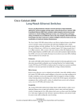
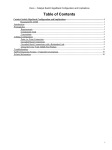
Data Sheet
Cisco Catalyst 2950 Series Switches
with Standard Image Software
Product Overview
The Cisco® Catalyst® 2950SX-48, 2950T-48, 2950SX-24, 2950-24, and 2950-12 switches,
members of the Cisco Catalyst 2950 Series, are standalone, fixed-configuration, managed
10/100-Mbps switches providing basic workgroup connectivity for small to midsize
networks. These wire-speed desktop switches come with Standard Image software features
and offer Cisco IOS® Software functions for basic data, voice, and video services at the edge
of the network. Embedded in all Cisco Catalyst 2950 Series switches is the Cisco Cluster
Management Suite (CMS) software, which allows users to simultaneously configure and
troubleshoot multiple Cisco Catalyst desktop switches using a standard Web browser. In
addition, with the newly launched Cisco Express Setup, users now have the option to set up
the switch through a Web browser, eliminating the need for more complex terminal
emulation programs and knowledge of the command-line interface (CLI). Cisco Express
Setup reduces the cost of deployment by enabling less-skilled personnel to set up switches
quickly. This product line offers two distinct sets of software features and a range of
configurations to allow small, midsize, and enterprise branch offices to select the right
combination for the network edge. For networks that require additional security, advanced
quality of service (QoS), and high availability, Enhanced Image software delivers intelligent
services such as rate limiting and security filtering for deployment at the network edge.
The Cisco Catalyst 2950SX-48, 2950T-48, 2950SX-24, 2950-12 and 2950-24 switches
(Figures 1–5) are available only with the Standard Image (SI) software for the Cisco
Catalyst 2950 Series.
• Cisco Catalyst 2950SX-48 Switch—48 10/100-Mbps ports with two fixed
1000BASE-SX uplinks
• Cisco Catalyst 2950T-48 Switch—48 10/100-Mbps ports with two fixed 10/100/
1000BASE-T uplinks
• Cisco Catalyst 2950SX-24 Switch—24 10/100-Mbps ports with two fixed
1000BASE-SX uplinks
• Cisco Catalyst 2950-24 Switch— 24 10/100-Mbps ports
• Cisco Catalyst 2950-12 Switch—12 10/100-Mbps ports
Cisco Systems, Inc.
All contents are Copyright © 1992–2003 Cisco Systems, Inc. All rights reserved. Important Notices and Privacy Statement.
Page 1 of 15
Figure 1
Cisco Catalyst 2950-12 Switch
Figure 2
Cisco Catalyst 2950-24 Switch
Figure 3
Cisco Catalyst 2950SX-24 Switch
Figure 4
Cisco Catalyst 2950T-48 Switch
Figure 5
Cisco Catalyst 2950SX-48 Switch
Cisco Systems, Inc.
All contents are Copyright © 1992–2003 Cisco Systems, Inc. All rights reserved. Important Notices and Privacy Statement.
Page 2 of 15
These switches provide customers with many connectivity and port-density options. The Cisco Catalyst 2950-12
and Cisco Catalyst 2950-24 switches provide 12 and 24 10/100-Mbps ports, respectively, for edge connectivity.
Depending on port-density requirements, customers with gigabit fiber uplink connectivity needs can choose between
the Cisco Catalyst 2950SX-24 Switch, which provides 24 10/100-Mbps ports and 2 integrated 1000BASE-SX ports,
and the Cisco Catalyst 2950SX-48 Switch, which provides 48 10/100-Mbps ports and 2 integrated 1000BASE-SX
ports.
With these integrated ports, customers get an extremely cost-effective solution for delivering gigabit speeds using
fiber. These switches are ideal for education and government segments where fiber uplinks are required. For
customers that do not need fiber connectivity, the Cisco Catalyst 2950T-48 Switch with 48 10/100-Mbps ports and
two integrated 10/100/1000 BASE-T ports is a cost-effective alternative. The 10/100/1000 BASE-T ports can be used
for server connectivity or for uplink connectivity to distribution or other switches. Dual ports also provide
redundancy and increased availability, as well as provide a cost-effective means for cascading switches and managing
them as a cluster. The Cisco Catalyst 2950 Series Intelligent Ethernet switches with Enhanced Image software are
fixed-configuration models that bring intelligent services, such as advanced QoS, enhanced security, and high
availability to the network edge while maintaining the simplicity of traditional LAN switching. Combining a
Cisco Catalyst 2950 Series Intelligent Ethernet Switch with a Cisco Catalyst 3550 Series Switch enables IP routing
from the edge to the core of the network. Refer to the Cisco Catalyst 2950 Series Enhanced Image Data Sheet for
more information:
http://www.cisco.com/en/US/partner/products/hw/switches/ps628/products_data_sheet09186a00801a0c5b.html
Network Availability with Wire-Speed Performance in Connecting End Stations
to the LAN
With a switching fabric of 13.6 Gbps and a maximum forwarding bandwidth of 13.6 Gbps, Cisco Catalyst 2950
Series switches deliver wire-speed performance on all ports in connecting end stations and users to the company
LAN. Cisco Catalyst 2950 Series switches with basic services support performance-boosting features such as Cisco
Fast EtherChannel® to provide high-performance bandwidth between Cisco Catalyst switches, routers, and servers.
Network Security
Cisco Catalyst 2950 Series switches offer enhanced data security through a wide range of security features. These
features allow customers to provide network security based on users or MAC addresses. The security enhancements
are available free by downloading the latest software for the Cisco Catalyst 2950 Series switches.
Private VLAN Edge isolates ports on a switch, ensuring that traffic travels directly from the entry point to the
aggregation device through a virtual path and cannot be directed to another port. In addition, for authentication
of users with a TACACS+ or a RADIUS server, 802.1x provides port-level security. Simple Network Management
Protocol Version 3 (SNMPv3) (non-crypto) monitors and controls network devices as well as manages
configurations, performance, collection of statistics, and security.
With the Cisco Catalyst 2950SX-48, 2950T-48, 2950SX-24, 2950-24, and 2950-12 switches, network managers can
make ports and consoles highly secure. MAC-address-based port-level security prevents unauthorized stations from
accessing the switch. Multilevel access security on the switch console and the Web management interface prevents
unauthorized users from accessing or altering switch configurations and can be implemented using an internal user
database on each switch or a centrally administered TACACS+ or RADIUS server. Using 802.1x in conjunction with
Cisco Systems, Inc.
All contents are Copyright © 1992–2003 Cisco Systems, Inc. All rights reserved. Important Notices and Privacy Statement.
Page 3 of 15
a RADIUS server allows dynamic port-based user authentication. In addition, 802.1x can coexist with port security
on a per-port basis. Security features can be deployed using Cisco CMS software security wizards, which ease the
deployment of security features that restrict user access to a server or portion of the network or restrict the
applications used in certain areas of the network.
Network Control
Cisco Catalyst 2950SX-48, 2950T-48, 2950SX-24, 2950-24, and 2950-12 switches deliver LAN-edge QoS,
supporting two modes of reclassification. One mode—based on the IEEE 802.1p standard—honors the
class-of-service (CoS) value at the ingress point and assigns the packet to the appropriate queue. In the second mode,
packets can be reclassified based on a default CoS value assigned to the ingress port by the network administrator.
In the case of frames that arrive without a CoS value (such as untagged frames), these Cisco Catalyst 2950 Series
switches support classification based on a default CoS value per port assigned by the network administrator. After
the frames have been classified or reclassified using one of the above modes, they are assigned to the appropriate
queue at the egress. Cisco Catalyst 2950 Series switches support four egress queues, which allow the network
administrator to be more discriminating and granular in assigning priorities for the various applications on the LAN.
Strict Priority Scheduling configuration ensures that time-sensitive applications, such as voice, always follow an
expedited path through the switch fabric. Weighted Round Robin (WRR) scheduling, another significant
enhancement, ensures that lower-priority traffic receives attention without comprising the priority settings
administered by a network manager. These features allow network administrators to prioritize mission-critical,
time-sensitive traffic, such as voice (IP telephony traffic), enterprise resource planning (Oracle, SAP, etc.), and
computer-assisted design and manufacturing, over less time-sensitive applications such as FTP or e-mail (Simple Mail
Transfer Protocol).
Network Availability
To provide efficient use of resources for bandwidth-hungry applications like multicasts, Cisco Catalyst 2950 Series
switches support Internet Group Management Protocol Version 3 (IGMPv3) snooping in hardware. Through the
support and configuration of IGMP snooping through the Cisco CMS software, these Cisco Catalyst 2950 Series
switches deliver outstanding performance and ease of use in administering and managing multicast applications on
the LAN.
The IGMPv3 snooping feature allows the switch to “listen in” on the IGMP conversation between hosts and routers.
When a switch hears an IGMP join request from a host for a given multicast group, the switch adds the host’s port
number to the group destination address list for that group. And when the switch hears an IGMP leave request, it
removes the host’s port from the content-addressable memory (CAM) table entry.
Multicast VLAN Registration (MVR) is designed for applications using wide-scale deployment of multicast traffic
across an Ethernet ring-based service provider network (for example, the broadcast of multiple television channels
over a service-provider network). MVR allows a subscriber on a port to subscribe and unsubscribe to a multicast
stream on the networkwide multicast VLAN.
Per VLAN Spanning Tree Plus (PVST+) allows users to implement redundant uplinks while also distributing traffic
loads across multiple links. This is not possible with standard Spanning Tree Protocol implementations. Cisco
UplinkFast technology ensures immediate transfer to the secondary uplink, much better than the traditional 30- to
60-second convergence time. This is yet another enhancement of the Spanning Tree Protocol implementation. An
Cisco Systems, Inc.
All contents are Copyright © 1992–2003 Cisco Systems, Inc. All rights reserved. Important Notices and Privacy Statement.
Page 4 of 15
additional feature that enhances performance is voice VLAN. This feature allows network administrators to assign
voice traffic to a VLAN dedicated to IP telephony, thereby simplifying phone installations and providing easier
network traffic administration and troubleshooting.
Network Management
Cisco Cluster Management Suite (CMS) is Web software that is embedded in Cisco Catalyst 3750, 3550, 2970, 2950,
2940, 3500 XL, 2900 XL, and 2900 LRE XL series switches. Through Cisco switch-clustering technology, users
access Cisco CMS software with any standard Web browser to manage up to 16 of these switches at once, regardless
of their geographic proximityæwith the option of using a single IP address for the entire cluster if desired. Cisco CMS
software supports standards-based connectivity options such as Ethernet, Fast Ethernet, Fast EtherChannel, Gigabit
Ethernet, and Gigabit EtherChannel connectivity. Because Cisco switch-clustering technology is not limited to a
single stack of switches, Cisco CMS software expands the traditional cluster domain beyond a single wiring closet
and saves time and effort for network administrators.
Cisco Catalyst 2950 Series switches can be configured either as command or member switches in a Cisco switch
cluster. Cisco CMS also allows the network administrator to designate a standby or redundant command switch,
which takes the commander duties should the primary command switch fail. Other key features include the ability
to configure multiple ports and switches simultaneously, as well as perform software updates across the entire cluster
at once, and clone configurations to other clustered switches for rapid network deployment. Bandwidth graphs and
link reports provide useful diagnostic information, and the topology map gives network administrators a quick view
of network status.
In addition to CMS, Cisco Catalyst 2950 Series switches provide extensive management tools using SNMP network
management platforms such as CiscoWorks.
Cisco Catalyst 2950 Series switches deliver a comprehensive set of management tools to provide the required
visibility and control in the network. Managed with CiscoWorks, Cisco Catalyst family switches can be configured
and managed to deliver end-to-end device, VLAN, traffic, and policy management. Coupled with CiscoWorks, Cisco
Resource Manager Essentials, a Web-based management tool, offers automated inventory collection, software
deployment, easy tracking of network changes, views into device availability, and quick isolation of error conditions.
Cisco Express Setup is a new feature that simplifies initial configuration of a switch. Users now have the option to
set up the switch using a Web browser, eliminating the need for more complex terminal emulation programs and
knowledge of CLI. Cisco Express Setup reduces the cost of deployment by enabling less-skilled personnel to set up
switches quickly and simply.
Cisco Systems, Inc.
All contents are Copyright © 1992–2003 Cisco Systems, Inc. All rights reserved. Important Notices and Privacy Statement.
Page 5 of 15
Product Features and Benefits
Feature
Benefit
Availability
Superior redundancy
for fault backup
• IEEE 802.1D Spanning Tree Protocol support for redundant backbone connections and
loop-free networks simplifies network configuration and improves fault tolerance.
• Support for Cisco Spanning Tree Protocol enhancements such as UplinkFast,
BackboneFast, and PortFast technologies ensures quick failover recovery and enhances
overall network stability and availability.
• Support for an optional 675W redundant Cisco AC power system provides a backup
power source for as many as four units or six units, respectively, for improved fault
tolerance and network uptime.
• Unidirectional link detection (UDLD) and aggressive UDLD detect and disable
unidirectional links on fiber-optic interfaces caused by incorrect fiber-optic wiring or
port faults.
Integrated Cisco IOS
Software features
for bandwidth
optimization
• Bandwidth aggregation through Cisco EtherChannel technology enhances fault tolerance
and offers higher-speed aggregated bandwidth between switches to routers and
individual servers. Port Aggregation Protocol (PagP) is available to simplify configuration.
• VLAN1 minimization allows VLAN1 to be disabled on any individual VLAN trunk link.
• Per-port broadcast, multicast, and unicast storm control prevents faulty end stations from
degrading overall system performance.
• Per VLAN Spanning Tree Plus (PVST+) allows for Layer 2 load sharing on redundant links
to efficiently use the extra capacity inherent in a redundant design.
• VLAN Trunking Protocol (VTP) pruning limits bandwidth consumption on VTP trunks by
flooding broadcast traffic only on trunk links required to reach the destination devices.
Dynamic Trunking Protocol (DTP) enables dynamic trunk configuration across all ports in
the switch.
• IGMPv3 snooping provides for fast client joins and leaves of multicast streams and limits
bandwidth-intensive video traffic to the requestors. MVR, IGMP filtering, and fast-join and
immediate leave are available as enhancements.
Cisco Systems, Inc.
All contents are Copyright © 1992–2003 Cisco Systems, Inc. All rights reserved. Important Notices and Privacy Statement.
Page 6 of 15
Feature
Benefit
Security
Networkwide
security features
• A private VLAN edge provides security and isolation between ports on a switch, ensuring
that voice traffic travels directly from its entry point to the aggregation device through a
virtual path and cannot be directed to a different port.
• Support for the 802.1x standard allows users to be authenticated regardless of which LAN
ports they are accessing, and it provides unique benefits to customers who have a large
base of mobile (wireless) users accessing the network.
• 802.1x with voice VLAN permits an IP phone access to the voice VLAN regardless of the
authorized or unauthorized state of the port.
• 802.1x with Port Security authenticates the port and manages network access for all MAC
addresses, including that of the client.
• Port Security secures the access to a port based on the MAC address of a user’s device.
The aging feature removes the MAC address from the switch after a specific time to allow
another device to connect to the same port.
• MAC Address Notification allows administrators to be notified of new users added or
removed from the network.
• Multilevel security on console access prevents unauthorized users from altering the
switch configuration.
• Trusted Boundary provides the ability to trust the QoS priority settings if an IP phone is
present and disable the trust setting in the event that the IP phone is removed, thereby
preventing a rogue user from overriding prioritization policies in the network.
• TACACS+ and RADIUS authentication enables centralized control of the switch and
restricts unauthorized users from altering the configuration.
• SNMPv3 (non-crypto) monitors and controls network devices, manages configurations,
statistics collection, performance, and security.
• Cisco CMS software security wizards ease the deployment of security features for
restricting user access to a server, a portion of the network, or access to the network.
Quality of Service
Layer 2 QoS
• Support for reclassifying frames is based either on 802.1p class-of-service (CoS) value or
default CoS value per port assigned by network manager.
• Four queues per egress port are supported in hardware.
• The Weighted Round Robin (WRR) scheduling algorithm ensures that low-priority queues
are not starved.
• Strict priority queue configuration via Strict Priority Scheduling ensures that
time-sensitive applications such as voice always follow an expedited path through the
switch fabric.
Cisco Systems, Inc.
All contents are Copyright © 1992–2003 Cisco Systems, Inc. All rights reserved. Important Notices and Privacy Statement.
Page 7 of 15
Feature
Benefit
Management
Superior
manageability
• SNMP and Telnet interface support delivers comprehensive in-band management, and a
CLI management console provides detailed out-of-band management.
• An embedded Remote Monitoring (RMON) software agent supports four RMON groups
(history, statistics, alarms, and events) for enhanced traffic management, monitoring, and
analysis.
• A Switched Port Analyzer (SPAN) port can mirror traffic from one or many ports to another
port for monitoring all nine RMON groups with an RMON probe or network analyzer.
• Trivial File Transfer Protocol (TFTP) reduces the cost of administering software upgrades
by downloading from a centralized location.
• Network Timing Protocol (NTP) provides an accurate and consistent timestamp to all
switches within the intranet.
• Layer 2 traceroute eases troubleshooting by identifying the physical path that a packet
takes from the source device to a destination device.
• Multifunction LEDs per port for port status, half-duplex/full-duplex, 10BASE-T/
100BASE-TX/1000BASE-T indication, as well as switch-level status LEDs for system,
redundant power supply, and bandwidth utilization provide a comprehensive and
convenient visual management system.
• Crash information support enables a switch to generate a crash file for improved
troubleshooting.
• Show-interface-capabilities provide information about the configuration capabilities of
any interface.
• Response Time Monitoring (RTTMON) MIB allows users to monitor network performance
between a Cisco Catalyst switch and a remote device.
Cisco Systems, Inc.
All contents are Copyright © 1992–2003 Cisco Systems, Inc. All rights reserved. Important Notices and Privacy Statement.
Page 8 of 15
Feature
Benefit
Cisco Cluster
Management Suite
• Cisco Cluster Management Suite (CMS) software allows the user to manage up to 16
interconnected Cisco Catalyst 3750, 2970, 2950, 2940, 3500XL, 2900XL, and 2900 LRE XL
series switches without the limitation of being located in the same wiring closet, and with
the option of using a single IP address for the entire cluster if desired. Full backward
compatibility ensures that any combination of the above switches can be managed with
a Cisco Catalyst 2950 Series Switch.
• Cisco AVVID (Architecture for Voice, Video and Integrated Data) wizards use just a few
user inputs to automatically configure the switch to optimally handle different types of
traffic: voice, video, multicast, and high-priority data.
• One-click software upgrades can be performed across the entire cluster simultaneously,
and configuration cloning enables rapid deployment of networks.
• Cisco CMS Guide Mode helps users configure powerful advanced features by providing
step-by-step instructions.
• Cisco CMS provides enhanced online help for context-sensitive assistance.
• Easy-to-use graphical interface provides both a topology map and front-panel view of the
cluster.
• Cisco CMS Client Install improves the launch time of Cisco CMS by installing the software
files on the management station.
• Multidevice- and multiport-configuration capabilities allow network administrators to
save time by configuring features across multiple switches and ports simultaneously.
• Cisco CMS allows the launch of the Web-based management for a Cisco Aironet®
Wireless Access Point simply by clicking its icon in the topology map.
• User-personalized interface allows users to modify polling intervals, table views, and
other settings within Cisco CMS and retain these settings the next time they use
Cisco CMS.
• Alarm notification provides automated e-mail notification of network errors and alarm
thresholds.
• A Cisco CMS plug-in enables configuration of the management station with the correct
run-time software.
Support for
CiscoWorks
• Manageability is enabled through CiscoWorks network management software on a
per-port and per-switch basis, providing a common management interface for Cisco
routers, switches, and hubs.
• SNMPv1, v2, and v3 (non-crypto) and Telnet interface support delivers comprehensive
in-band management, and a command-line-interface (CLI) management console provides
detailed out-of-band management.
• Cisco Discovery Protocol (CDP) versions 1 and 2 enable a CiscoWorks network
management station to automatically discover the switch in a network topology.
• Support is provided by the CiscoWorks LAN Management Solution.
Cisco Systems, Inc.
All contents are Copyright © 1992–2003 Cisco Systems, Inc. All rights reserved. Important Notices and Privacy Statement.
Page 9 of 15
Feature
Benefit
Ease of use and
deployment
• Cisco Express Setup:
– Simplifies initial configuration of a switch via a Web browser, eliminating the need for
more complex terminal emulation programs and CLI knowledge.
– Reduces the cost of deployment by enabling less-skilled personnel to set up switches
quickly and simply.
• Auto-configuration eases deployment of switches in the network by automatically
configuring multiple switches across a network using a bootp server.
• Autosensing on each port detects the speed of the attached device and automatically
configures the port for 10- or 100-Mbps operation, easing the deployment of the switch
in mixed-speed environments.
• Auto-negotiating on all ports automatically selects half- or full-duplex transmission mode
to optimize bandwidth.
• Link Aggregation Control Protocol (LACP) allows the creation of Ethernet channeling with
devices that conform to IEEE 802.3ad. This is similar to Cisco EtherChannel and PagP.
• Cisco Discovery Protocol versions 1 and 2 enable a CiscoWorks network management
station to automatically discover the switch in a network topology.
• Cisco VTP supports dynamic VLANs and dynamic trunk configuration across all switches.
• Support for dynamic VLAN assignment through implementation of VLAN Membership
Policy Server (VMPS) client functions provides flexibility in assigning ports to VLANs.
• Voice VLAN simplifies telephony installations by keeping voice traffic on a separate VLAN
for easier network administration and troubleshooting.
• The default configuration stored in Flash memory ensures that the switch can be quickly
connected to the network and can pass traffic with minimal user intervention.
Cisco Systems, Inc.
All contents are Copyright © 1992–2003 Cisco Systems, Inc. All rights reserved. Important Notices and Privacy Statement.
Page 10 of 15
Product Specifications
Feature
Description
Performance
•
•
•
•
•
•
•
•
•
•
•
•
•
•
•
13.6-Gbps switching fabric
Cisco Catalyst 2950-12: 2.4-Gbps maximum forwarding bandwidth
Cisco Catalyst 2950-24: 4.8-Gbps maximum forwarding bandwidth
Cisco Catalyst 2950SX-24: 8.8-Gbps maximum forwarding bandwidth
Cisco Catalyst 2950T-48: 13.6-Gbps maximum forwarding bandwidth
Cisco Catalyst 2950SX-48: 13.6-Gbps maximum forwarding bandwidth
(Forwarding rates based on 64-byte packets)
Cisco Catalyst 2950-12: 1.8-Mpps wire-speed forwarding rate
Cisco Catalyst 2950-24: 3.6-Mpps wire-speed forwarding rate
Cisco Catalyst 2950SX-24: 6.6-Mpps wire-speed forwarding rate
Cisco Catalyst 2950T-48: 10.1-Mpps wire-speed forwarding rate
Cisco Catalyst 2950SX-48: 10.1-Mpps wire-speed forwarding rate
8 MB packet buffer memory architecture shared by all ports
16 MB DRAM and 8 MB Flash memory
Configurable up to 8000 MAC addresses
Feature
Description/Part Numbers
Management
•
•
•
•
•
•
•
•
•
•
•
•
•
•
•
•
•
•
•
•
•
•
•
•
BRIDGE-MIB
CISCO-2900-MIB
CISCO-BULK-FILE-MIB
CISCO-CDP-MIB
CISCO-CLASS-BASED-QOS-MIB
CISCO-CLUSTER-MIB
CISCO-CONFIG-COPY-MIB
CISCO-CONFIG-MAN-MIB
CISCO-ENVMON-MIB
CISCO-FLASH-MIB
CISCO-FTP-CLIENT-MIB
CISCO-IMAGE-MIB
CISCO-IPMROUTE-MIB
CISCO-MAC-NOTIFICATION-MIB
CISCO-MEMORY-POOL-MIB
CISCO-PAGP-MIB
CISCO-PING-MIB
CISCO-PROCESS-MIB
CISCO-PRODUCTS-MIB
CISCO-RTTMON-MIB
CISCO-SMI
CISCO-STACKMAKER-MIB
CISCO-STP-EXTENSIONS-MIB
CISCO-SYSLOG-MIB
•
•
•
•
•
•
•
•
•
•
•
•
•
•
•
•
•
•
•
•
•
•
•
•
CISCO-TC
CISCO-TCP-MIB
CISCO-VLAN-MEMBERSHIP-MIB
CISCO-VTP-MIB
ENTITY-MIB
IANAifType-MIB
IF-MIB (RFC 1573)
OLD-CISCO-CHASSIS-MIB
OLD-CISCO-CPU-MIB
OLD-CISCO-INTERFACES-MIB
OLD-CISCO-IP-MIB
OLD-CISCO-MEMORY-MIB
OLD-CISCO-SYSTEM-MIB
OLD-CISCO-TCP-MIB
OLD-CISCO-TS-MIB
RFC1213-MIB (MIB-II)
RFC1398-MIB (ETHERNET-MIB)
RMON-MIB (RFC 1757)
RS-232-MIB
SNMPv2-MIB
SNMPv2-SMI
SNMPv2-TC
TCP-MIB
UDP-MIB
Cisco Systems, Inc.
All contents are Copyright © 1992–2003 Cisco Systems, Inc. All rights reserved. Important Notices and Privacy Statement.
Page 11 of 15
Feature
Description/Part Numbers
Standards
•
•
•
•
•
•
•
•
•
Connectors
and cabling
• 10BASE-T ports: RJ-45 connectors, two-pair Category 3, 4, or 5 unshielded twisted-pair (UTP)
cabling
• 100BASE-TX ports: RJ-45 connectors; two-pair Category 5 UTP cabling
• 1000BASE-SX ports: MT-RJ connectors, up to 1800 feet (550 meters) cable distance for 50/125
or up to 900 ft (275 m) cable distance for 62.5/125 micron multimode fiber-optic cabling
• Management console port: 8-pin RJ-45 connector, RJ-45-to-DB9 adapter cable for PC
connections; for terminal connections, use RJ-45-to-DB25 female data-terminal-equipment
(DTE) adapter (can be ordered separately, Cisco part number ACS-DSBUASYN=)
MT-RJ patch
cables for
Cisco Catalyst
2950SX-24
Switch
Type of cable, Cisco part number:
Power
connectors
Customers can provide power to a switch by using the internal power supply, the Cisco RPS 675
Redundant Power System. The connectors are located at the back of the switch.
•
•
•
•
•
•
IEEE 802.1x support
IEEE 802.3x full duplex on 10BASE-T and 100BASE-TX ports
IEEE 802.1D Spanning-Tree Protocol
IEEE 802.1p class-of-service (CoS) prioritization
IEEE 802.1Q VLAN
IEEE 802.3 10BASE-T specification
IEEE 802.3u 100BASE-TX specification
IEEE 802.3ad
IEEE 802.3z 1000BASE-X specification
1-meter MT-RJ-to-SC multimode cable, CAB-MTRJ-SC-MM-1M
3-meter MT-RJ-to-SC multimode cable, CAB-MTRJ-SC-MM-3M
5-meter MT-RJ-to-SC multimode cable, CAB-MTRJ-SC-MM-5M
1-meter MT-RJ-to-ST multimode cable, CAB-MTRJ-ST-MM-1M
3-meter MT-RJ-to-ST multimode cable, CAB-MTRJ-ST-MM-3M
5-meter MT-RJ-to-ST multimode cable, CAB-MTRJ-ST-MM-5M
Internal power supply connector:
• The internal power supply is an auto-ranging unit.
• The internal power supply supports input voltages between 100 and 240 VAC.
• Use the supplied AC power cord to connect the AC power connector to an AC power outlet.
Cisco RPS 675 connector:
• The connector offers connection for an optional Cisco RPS 675 that uses AC input and supplies
DC output to the switch.
• The connector offers a 675W redundant power system that supports six external network
devices and provides power to one failed device at a time.
• The connector automatically senses when the internal power supply of a connected device
fails and provides power to the failed device, preventing loss of network traffic.
• Attach only the Cisco RPS 675 (Model PWR675-AC-RPS-NI=) to the redundant power supply
receptacle with this connector.
Indicators
• Per-port status LEDs: link integrity, disabled, activity, speed, and full-duplex indications
• System status LEDs: system, RPS, and bandwidth-utilization indications
Dimensions
and weight
(H x W x D)
•
•
•
•
•
1.72 x 17.5 x 9.52 in. (4.36 x 44.45 x 24.18 cm) (Cisco Catalyst 2950SX-24, 2950-24, 2950-12)
1.72 x 17.5 x 13 in. (4.36 x 44.45 x 33.02 cm) (Cisco Catalyst 2950SX-48, 2950T-48)
1 RU high (1.72 in./4.36 cm)
6.5 lb (3.0 kg) (Cisco Catalyst 2950SX-24, 2950-24, 2950-12)
10.b lb (4.8 kg) (Cisco Catalyst 2950SX-48, 2950T-48)
Cisco Systems, Inc.
All contents are Copyright © 1992–2003 Cisco Systems, Inc. All rights reserved. Important Notices and Privacy Statement.
Page 12 of 15
Feature
Description/Part Numbers
Environmental
ranges
•
•
•
•
•
Power
requirements
• Power consumption: 30W (maximum), 102 BTUs per hour (Cisco Catalyst 2950SX-24, 2950-24.
2950-12)
• Power consumption: 45W (maximum), 154 BTUs per hour (Cisco Catalyst 2950T-48, 2950SX-48)
• AC input voltage: 100 to 127, 200 to 240 VAC (auto-ranging)
• AC input frequency: 47 to 63 Hz
• DC input voltages for Cisco RPS 675 and Cisco RPS 300: +12V at 4.5A
Acoustic noise
Predicted mean
time between
failure
ISO 7770, bystander position, operating to an ambient temperature of 86 F (30 C):
• WS-C2950-24, WS-C2950-12, WS-C2950SX-24: 46 dBa
• WS-C2950T-48-SI, WS-C2950SX-48-SI: 48 dBa
• 268,292 hours (Cisco Catalyst 2950-24)
• 318,440 hours (Cisco Catalyst 2950-12)
• 403,214 hours (Cisco Catalyst 2950SX-24)
• 268,876 hours (Cisco Catalyst 2950T-48-SI)
• 274,916 hours (Cisco Catalyst 2950SX-48-SI)
Operating temperature: 32 to 113 F (0 to 45 C)
Storage temperature: –13 to 158 F (–25 to 70 C)
Operating relative humidity: 10–85% (non-condensing)
Operating altitude: Up to 10,000 ft (3000 m)
Storage altitude: Up to 15,000 ft (4500 m)
Regulatory Agency Approvals
Safety
certifications
•
•
•
•
UL 60950/CSA 22.2 No. 950
IEC 60950/EN 60950
AS/NZS 3260, TS001
CE Marking
Electromagnetic
emissions
certifications
•
•
•
•
•
•
•
•
•
FCC Part 15 Class A
EN 55022: 1998 (CISPR 22) Class A
EN 55022: 1998 (CISPR 22)
VCCI Class A
AS/NZS 3548 Class A
CE Marking
CNS 13438 Class A
CLEI Code
MIC
Warranty
• Lifetime limited warranty
Cisco Systems, Inc.
All contents are Copyright © 1992–2003 Cisco Systems, Inc. All rights reserved. Important Notices and Privacy Statement.
Page 13 of 15
Service and Support
The services and support programs described here are available as part of the Cisco Desktop Switching Service and
Support solution and are available directly from Cisco Systems® and through resellers.
Service and Support
Features
Benefits
•
•
•
•
•
•
Project management
Site survey, configuration deployment
Installation, text, and cutover
Training
Major moves, adds, changes
Design review and product staging
• Supplements existing staff
• Ensures that functions meet needs
• Mitigates risk
• Around-the-clock access to software
updates
• Web access to technical repositories
• Telephone support through the Technical
Assistance Center
• Advance replacement of hardware parts
• Enables proactive or expedited
issue resolution
• Lowers cost of ownership by using
Cisco expertise and knowledge
• Minimizes network downtime
Advanced Services
Total Implementation
Solutions (TIS)—Available
direct from Cisco
Packaged Total
Implementation Solutions
(Packaged TIS)—Available
through resellers
Technical Support Services
Cisco SMARTnet® services
and Cisco SMARTnet
Onsite services—Available
direct from Cisco
Packaged Cisco SMARTnet
services—Available
through resellers
Ordering Information
Model Numbers
Configuration
WS-C2950-12
• 12 10/100-Mbps ports
• 1-RU standalone, fixed-configuration, managed 10/100-Mpbs switch
• Standard Image (SI) Software
WS-C2950-24
• 24 10/100-Mpbs ports
• 1-RU standalone, fixed-configuration, managed 10/100-Mbps switch
• Standard Image (SI) Software
WS-C2950SX-24
• 24 10/100-Mpbs ports with two fixed 1000BASE-SX uplinks
• 1-RU standalone, fixed-configuration, managed 10/100-Mbps switch
• Standard Image (SI) Software
WS-C2950T-48-SI
• 48 10/100-Mbps ports with two fixed 10/100/1000BASE-T uplinks
• 1-RU standalone, fixed-configuration, managed 10/100-Mbps switch
• Standard Image (SI) Software
WS-C2950SX-48-SI
• 48 10/100-Mbps ports with two fixed 1000BASE-SX uplinks
• 1-RU standalone, fixed-configuration, managed 10/100-Mbps switch
• Standard Image (SI) Software
Cisco Systems, Inc.
All contents are Copyright © 1992–2003 Cisco Systems, Inc. All rights reserved. Important Notices and Privacy Statement.
Page 14 of 15
For More Information
For more information about Cisco products, contact:
• United States and Canada: 800 553-NETS (6387)
• Europe: 32 2 778 4242
• Australia: 612 9935 4107
• Other: 408 526-7209
• World Wide Web: http://www.cisco.com