1
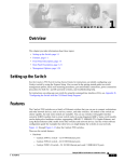
C H A P T E R
1
Overview
This chapter provides information about the following topics:
•
Switch features
•
Front- and rear-panel descriptions
•
Management options
Features
The Catalyst 2950 series switches are stackable Ethernet switches to which you
can connect workstations and other network devices, such as servers, routers, and
other switches. The switches can be deployed as backbone switches, aggregating
10BASE-T, 100BASE-TX, and Gigabit Ethernet traffic from other network
devices. Refer to the Catalyst 2950 Desktop Switch Software Configuration Guide
for examples showing how you might deploy the switches in your network.
Figure 1-1 shows the Catalyst 2950 series switches, and Table 1-1 lists the switch
features.
Catalyst 2950 Desktop Switch Hardware Installation Guide
78-11157-01
1-1
Chapter 1
Overview
Features
Catalyst 2950 Series Switches
Version Number
Description
WS-C2950-12
12 fixed autosensing 10/100 ports
Switch
SYST
RPS
STAT
UTIL DUPLX
1x
2x
3x
4x
5x
SPEED
6x
7x
8x
MODE
WS-C2950-24
24 fixed autosensing 10/100 ports
SYST
RPS
STAT
UTIL DUPLX
1x
2x
3x
4x
5x
SPEED
6x
7x
8x
MODE
WS-C2950C-24
24 fixed autosensing 10/100 ports
2 100BASE-FX ports
SYST
RPS
STAT
UTIL DUPLX
1x
2x
3x
4x
5x
SPEED
6x
7x
8x
MODE
9x
9x
9x
10x
10x
10x
11x
11x
11x
10BASE
-T / 100BAS
E-TX
12x
Catalyst 2950
SERIES
Catalyst 2950
SERIES
Catalyst 2950
SERIES
10BASE
-T / 100BAS
E-TX
12x
13x
14x
15x
16x
17x
18x
19x
20x
21x
22x
23x
24x
10BASE
-T / 100BAS
E-TX
12x
13x
14x
15x
16x
17x
18x
19x
20x
21x
22x
23x
24x
100BAS
E-FX
25
WS-C2950T-24
24 fixed autosensing 10/100 ports
2 fixed autosensing 10/100/1000
ports
SYST
RPS
STAT
UTIL DUPLX
1x
2x
3x
SPEED
MODE
4x
5x
6x
7x
8x
9x
10x
11x
26
10BASE
-T / 100BAS
E-TX
12x
13x
14x
15x
16x
17x
18x
19x
20x
Catalyst 2950
21x
22x
23x
24x
SERIES
10/100/1000BA
1
SE-T
2
47268
Figure 1-1
Catalyst 2950 Desktop Switch Hardware Installation Guide
1-2
78-11157-01
Chapter 1
Overview
Front-Panel Description
Table 1-1
Catalyst 2950 Switch Features
Feature
Hardware
Configuration
Power redundancy
Description
•
12 10/100 Ethernet ports
•
24 10/100 Ethernet ports
•
24 10/100 Ethernet ports and 2 100BASE-FX ports
•
24 10/100 Ethernet ports and 2 10/100/1000 Ethernet ports
•
Autonegotiates the speed and duplex settings on 10/100 ports and
on 10/100/1000 ports
•
Autonegotiates the duplex setting on 100BASE-FX ports
•
Supports 8192 MAC addresses
•
Checks for errors on a received packet, determines the destination
port, stores the packet in shared memory, and then forwards the
packet to the destination port
•
Connection for an optional Cisco RPS 300 Redundant Power
System (RPS) that uses AC input and supplies DC output to the
switch
Front-Panel Description
The switch front panels contain the ports, the LEDs, and the Mode button. The
Catalyst 2950-12 switch (see Figure 1-2) and Catalyst 2950-24 switch (see
Figure 1-3) have 10/100 ports. The Catalyst 2950C-24 switch has 10/100 ports
and 100BASE-FX ports. (See Figure 1-4.) The Catalyst 2950T-24 switch has
10/100 ports and 10/100/1000 ports. (See Figure 1-5.)
Catalyst 2950 Desktop Switch Hardware Installation Guide
78-11157-01
1-3
Chapter 1
Overview
Front-Panel Description
SYST
RPS
STAT
UTIL DUPLX
1x
2x
Catalyst 2950-12 Switch
3x
4x
5x
SPEED
6x
7x
8x
MODE
9x
10x
10Base-T
11x
/ 100Base-
TX
12x
Catalyst 295
0 SERIES
45568
Figure 1-2
10/100 ports
SYST
RPS
STAT
UTIL DUPLX
1
2
Catalyst 2950-24 Switch
3
4x
5x
SPEED
6x
7x
8x
MODE
9x
10x
10Base-T
11x
/ 100Base-
TX
12x
13x
14x
15x
16x
17x
18x
19x
20x
Catalyst 295
21x
0 SERIES
22x
23x
45567
Figure 1-3
24x
10/100 ports
SYST
RPS
STAT
UTIL DUPLX
SPEED
MODE
1x
2x
Catalyst 2950C-24 Switch
3x
4x
5x
6x
7x
8x
9x
10x
10BASE-T
11x
/ 100BASE
-TX
12x
13x
14x
15x
16x
17x
18x
19x
20x
Catalyst 295
21x
0 SERIES
22x
23x
24x
100BASE
45570
Figure 1-4
-FX
25
26
10/100 ports
100BASE-FX ports
Catalyst 2950 Desktop Switch Hardware Installation Guide
1-4
78-11157-01
Chapter 1
Overview
Front-Panel Description
SYST
RPS
STAT
UTIL DUPLX
1x
2x
Catalyst 2950T-24 Switch
3x
SPEED
4x
5x
6x
7x
MODE
8x
9x
10x
10Base-T
11x
/ 100Base-
TX
12x
13x
14x
15x
16x
17x
18x
19x
20x
Catalyst 295
21x
0 SERIES
22x
23x
24x
10/100/1
47337
Figure 1-5
00Base-T
1
2
10/100 ports
10/100/1000 ports
10/100 Ports
The 10/100 ports use RJ-45 connectors and Category 5 cabling. These ports can
be explicitly set to operate in any combination of half duplex, full duplex,
10 Mbps, or 100 Mbps. They can also be set for speed and duplex autonegotiation,
compliant with IEEE 802.3u. In all cases, the cable length from a switch to an
attached device cannot exceed 328 feet (100 meters).
When set for autonegotiation, a port senses the speed and duplex settings of the
attached device and advertises its own capabilities. If the attached device supports
autonegotiation, the port negotiates the best connection (that is, the fastest line
speed that both devices support and full-duplex transmission, if the attached
device supports it) and configures itself accordingly.
100BASE-FX Ports
The 100BASE-FX ports use 50/125- or 62.5/125-micron multimode fiber-optic
cabling. In full-duplex mode (the default), the cable length from a switch to an
attached device cannot exceed 6562 feet (2 kilometers). In half-duplex mode, the
cable length cannot exceed 1352 feet (412 meters).
You can connect a 100BASE-FX port to an SC or ST port on a target device by
using one of the MT-RJ fiber-optic patch cables listed in Table 1-2. Use the Cisco
part numbers in Table 1-2 to order the patch cables that you need.
Catalyst 2950 Desktop Switch Hardware Installation Guide
78-11157-01
1-5
Chapter 1
Overview
Front-Panel Description
Table 1-2
MT-RJ Patch Cables
Type
Cisco Part Number
1-meter, MT-RJ-to-SC multimode cable
CAB-MTRJ-SC-MM-1M
3-meter, MT-RJ-to-SC multimode cable
CAB-MTRJ-SC-MM-3M
5-meter, MT-RJ-to-SC multimode cable
CAB-MTRJ-SC-MM-5M
1-meter, MT-RJ-to-ST multimode cable
CAB-MTRJ-ST-MM-1M
3-meter, MT-RJ-to-ST multimode cable
CAB-MTRJ-ST-MM-3M
5-meter, MT-RJ-to-ST multimode cable
CAB-MTRJ-ST-MM-5M
10/100/1000 Ports
The 10/100/1000 ports use RJ-45 connectors and Category 5 UTP cabling. These
ports can be explicitly set to operate at 10 or 100 Mbps in half- or full-duplex
mode or at 1000 Mbps in full-duplex mode. The default duplex setting is full
duplex. They can also be set for speed and duplex autonegotiation, compliant with
IEEE 802.3ab. In all cases, the cable length from a switch to an attached device
cannot exceed 328 feet (100 meters).
LEDs
You can use the LEDs to monitor switch activity and performance. Figure 1-6
shows the location of the LEDs and the Mode button that you use to select the port
mode. Changing the port mode changes the information provided by each port
status LED.
All of the LEDs described in this section except the utilization meter (UTIL) are
visible in the Cluster Management Suite (CMS). The Catalyst 2950 Desktop
Switch Software Configuration Guide describes how to use CMS to manage
individual switches and switch clusters.
Catalyst 2950 Desktop Switch Hardware Installation Guide
1-6
78-11157-01
Chapter 1
Overview
Front-Panel Description
Figure 1-6
LEDs
RPS
LED
Port status
LEDs
System
LED
SYST
RPS
Port mode
LEDs
STAT
UTIL D
UPLX
1x
2x
3x
SPEED
4x
5x
6x
MODE
52918
Mode button
System LED
The system LED shows whether the system is receiving power and functioning
properly. Table 1-3 lists the LED colors and meanings.
Table 1-3
System LED
Color
System Status
Off
System is not powered up.
Green
System is operating normally.
Amber
System is receiving power but is not functioning properly.
For information about the system LED colors during the power-on self-test
(POST), see the “Powering On the Switch and Running POST” section on
page 2-15.
Catalyst 2950 Desktop Switch Hardware Installation Guide
78-11157-01
1-7
Chapter 1
Overview
Front-Panel Description
RPS LED
The RPS LED shows the RPS status. Table 1-4 lists the LED colors and meanings.
Table 1-4
RPS LED
Color
RPS Status
Off
RPS is off or is not installed.
Solid green
RPS is connected and operational.
Blinking green RPS is backing up another switch in the stack.
Solid amber
RPS is connected but not functioning properly.
•
RPS could be in standby mode. Pressing the
Standby/Active button on the RPS puts it in Active mode,
and the LED should turn green. If the LED does not turn
green, check the RPS power supplies or fan.
•
One of the RPS power supplies could be down.
•
The RPS fan could have failed.
Blinking amber Internal power supply in this switch is down, and redundancy
is lost. The switch is operating on the RPS.
For more information about the Cisco RPS 300, refer to the Cisco RPS 300
Redundant Power System Hardware Installation Guide.
Port Mode and Port Status LEDs
Each port has a port status LED, also called a port LED. These LEDs, as a group
or individually, display information about the switch and the individual ports. The
port modes (see Table 1-5) determine the type of information displayed.
Catalyst 2950 Desktop Switch Hardware Installation Guide
1-8
78-11157-01
Chapter 1
Overview
Front-Panel Description
Table 1-5
Port Mode LEDs
Mode LED
Port Mode
Description
STAT
Port status
The port status. This mode is the default mode.
UTIL
Switch utilization
The current bandwidth in use by the switch.
DUPLX
Port duplex mode
The port duplex mode: half duplex or full duplex.
SPEED
Port speed
The port operating speed: 10 or 100 Mbps for 10/100 ports
and 10, 100, or 1000 Mbps for 10/100/1000 ports.
To select or change the port mode, press the Mode button (see Figure 1-7) to
highlight the mode you want. Release the button to enable the highlighted mode.
Figure 1-7
Changing the Port Mode
SYST
RPS
STAT
UTIL D
UPLX SP
EED
1x
2x
3x
4x
5x
6x
Mode button
52917
MODE
Catalyst 2950 Desktop Switch Hardware Installation Guide
78-11157-01
1-9
Chapter 1
Overview
Front-Panel Description
When you change the port mode, the meaning of the port LED colors changes.
Table 1-6 explains how to interpret the port LED colors.
Table 1-6
Meaning of Port LED Colors in Different Modes
Port Mode
Color
Meaning
STAT (port status)
Off
No link.
Solid green
Link present.
Flashing green Activity. Port is transmitting or receiving data.
Alternating
green-amber
Link fault. Error frames can affect connectivity, and errors such
as excessive collisions, CRC errors, and alignment and jabber
errors are monitored for a link-fault indication.
Solid amber
Port is not forwarding. Port was disabled by management or an
address violation, or it was blocked by Spanning Tree Protocol
(STP).
Note
UTIL (utilization)
After a port is reconfigured, the port LED can
remain amber for up to 30 seconds while STP
checks the switch for possible loops.
Green
The current backplane utilization that is displayed over the
amber LED background on a logarithmic scale.
Amber
The maximum backplane utilization since the switch was
powered on.
Green and
amber
If all LEDs are green (no amber showing), the switch is using
50% or more of the total bandwidth. If the right-most LED is
off, the switch is using more than 25% but less than 50% of the
total bandwidth, and so on. If only the left-most LED is green,
the switch is using less than 0.0488% of the total bandwidth.
See Figure 1-8 for details.
Note
DUPLX
Off
(half or full duplex) Green
If the current utilization exceeds the maximum
utilization, the maximum utilization is
automatically updated.
Port is operating in half duplex.
Port is operating in full duplex.
Catalyst 2950 Desktop Switch Hardware Installation Guide
1-10
78-11157-01
Chapter 1
Overview
Front-Panel Description
Table 1-6
Meaning of Port LED Colors in Different Modes (continued)
Port Mode
Color
Meaning
SPEED (speed)
10/100 ports
Off
Port is operating at 10 Mbps.
Green
Port is operating at 100 Mbps.
10/100/1000 ports
Off
Port is operating at 10 Mbps.
Green
Port is operating at 100 Mbps.
Flashing green Port is operating at 1000 Mbps.
Figure 1-8 shows the bandwidth utilization percentages displayed by the
right-most LEDs.
Figure 1-8
Bandwidth Utilization
Catalyst 2950 SERIES
10Base-T / 100Base-TX
1x
STAT
2x
3x
4x
5x
6x
7x
RPS
8x
9x
10x
11x
12x
47267
SYST
UTIL DUPLX SPEED
MODE
0–0.0487%+
6.25–12.4%+
12.5–24%+
25–49%+
50%+
Catalyst 2950 Desktop Switch Hardware Installation Guide
78-11157-01
1-11
Chapter 1
Overview
Rear-Panel Description
Rear-Panel Description
The switch rear panel has an AC power connector, an RPS connector, and an
RJ-45 console port. (See Figure 1-9.)
RATING
100-127V~
@ 1A
200-240V~
@0.5A
50-60Hz
Catalyst 2950 Switch Rear Panel
DC INPUT
FO
POWE R REMOTE
SPECIF R SUPPLY
IED IN
+12V @4MANUAL.
.5A
CONSOLE
AC power
connector
RPS
connector
Fan
45585
Figure 1-9
RJ-45
console port
Power Connectors
You can provide power to a switch either by using the internal power supply or
the Cisco RPS.
Internal Power Supply Connector
The internal power supply is an autoranging unit that supports input voltages
between 100 and 240 VAC. Use the supplied AC power cord to connect the AC
power connector to an AC power outlet.
Cisco RPS Connector
The RPS is a 300W redundant power system that can support six external network
devices and provides power to one failed device at a time. It automatically senses
when the internal power supply of a connected device fails and provides power to
Catalyst 2950 Desktop Switch Hardware Installation Guide
1-12
78-11157-01
Chapter 1
Overview
Management Options
the failed device, preventing loss of network traffic. When the internal power
supply has been brought up or replaced, the RPS automatically stops powering the
device.
Warning
Attach only the Cisco RPS 300 (model PWR300-AC-RPS-N1) to the RPS
receptacle.
For more information about the Cisco RPS 300, refer to the Cisco RPS 300
Redundant Power System Hardware Installation Guide.
Console Port
You can connect a switch to a PC through the console port and the supplied
rollover cable and DB-9 adapter. If you want to connect a switch to a terminal,
you need to provide an RJ-45-to-DB-25 female DTE adapter. You can order a kit
(part number ACS-DSBUASYN=) with that adapter from Cisco. For console-port
and adapter-pinout information, see the “Cable and Adapter Specifications”
section on page B-4.
Management Options
Catalyst 2950 series switches offer these management options:
•
Cluster Management Suite (CMS)
CMS is made up of three web-based applications that you use to manage
switches. You can use Cluster Builder, which includes Cluster View, and
Cluster Manager to create, monitor, and configure switch clusters. You can
also use Visual Switch Manager (VSM) to manage individual and standalone
switches. For more information, refer to the Catalyst 2950 Desktop Switch
Software Configuration Guide and the CMS online help.
•
IOS command-line interface (CLI)
You can manage switches using traditional command-line entries. To access
the CLI, connect a PC or terminal directly to the console port on the switch
rear panel. If the switch is attached to your network, you can use a Telnet
connection to manage the switch from a remote location. For more
information, refer to the Catalyst 2950 Desktop Switch Command Reference.
Catalyst 2950 Desktop Switch Hardware Installation Guide
78-11157-01
1-13
Chapter 1
Overview
Management Options
•
CiscoView application
You can use the CiscoView device-management application to set
configuration parameters and to view switch status and performance
information. This application, which you purchase separately, can be a
standalone application or part of an Simple Network Management Protocol
(SNMP) network-management platform. For more information, refer to the
documentation that came with your CiscoView application.
•
SNMP network management
You can manage switches by using an SNMP-compatible management station
running platforms such as HP OpenView and SunNet Manager. The switch
supports a comprehensive set of MIB extensions and MIB II, the
IEEE 802.1D bridge MIB, and four RMON groups. For more information,
refer to the documentation that came with your SNMP application.
Catalyst 2950 Desktop Switch Hardware Installation Guide
1-14
78-11157-01