1
DMX-55
DMX Controller
USER MANUAL
Chauvet, 3000 N 29th Ct, Hollywood, FL 33020 U.S.A
(800) 762-1084 – (954) 929-1115
FAX (954) 929-5560
www.chauvetlighting.com
TABLE OF CONTENT
BEFORE YOU BEGIN ...................................................................................................................................................... 3
WHAT IS INCLUDED................................................................................................................................................................................ 3
UNPACKING INSTRUCTIONS .................................................................................................................................................................... 3
SAFETY INSTRUCTIONS .......................................................................................................................................................................... 3
INTRODUCTION............................................................................................................................................................... 4
FEATURES ............................................................................................................................................................................................ 4
GENERAL OVERVIEW............................................................................................................................................................................. 4
PRODUCT OVERVIEW (FRONT) ............................................................................................................................................................... 5
CONNECTION DIAGRAM (REAR) .............................................................................................................................................................. 6
LCD DISPLAY TABLE OF DEFINITIONS ..................................................................................................................................................... 6
COMMON TERMS .................................................................................................................................................................................. 7
OPERATING INSTRUCTIONS.......................................................................................................................................... 8
SETUP ................................................................................................................................................................................................. 8
Setting up the system ........................................................................................................................................................................................ 8
Fixture patch ...................................................................................................................................................................................................... 8
Joystick setup..................................................................................................................................................................................................... 9
Reverse DMX channel and joystick................................................................................................................................................................... 9
Deleting a scanner’s dmx channel settings ..................................................................................................................................................... 10
Clear all scanner’s DMX channels................................................................................................................................................................... 10
Display Pan/Tilt DMX channels ....................................................................................................................................................................... 10
Fade time settings............................................................................................................................................................................................ 10
Scene Programming ........................................................................................................................................................................................ 11
Entering programming mode ........................................................................................................................................................................... 11
Create a scene................................................................................................................................................................................................. 11
Scene edit ........................................................................................................................................................................................................ 11
Copy scanner settings ..................................................................................................................................................................................... 12
Copy scene ...................................................................................................................................................................................................... 12
Delete scene .................................................................................................................................................................................................... 12
Delete all scenes.............................................................................................................................................................................................. 12
Copy bank........................................................................................................................................................................................................ 12
CHASE PROGRAMMING ........................................................................................................................................................................ 13
Create a chase................................................................................................................................................................................................. 13
Inserting a bank of scenes into a chase .......................................................................................................................................................... 13
Add a step ........................................................................................................................................................................................................ 14
Delete a step.................................................................................................................................................................................................... 14
Delete a chase ................................................................................................................................................................................................. 14
Delete all chases.............................................................................................................................................................................................. 15
PLAYBACK (SCENES) .......................................................................................................................................................................... 15
Manual run scene ............................................................................................................................................................................................ 15
Running in Sound-Mode .................................................................................................................................................................................. 15
Running in Auto-Mode ..................................................................................................................................................................................... 15
Blackout ........................................................................................................................................................................................................... 15
PLAYBACK (CHASES) .......................................................................................................................................................................... 16
Manual run chases........................................................................................................................................................................................... 16
Auto run chases ............................................................................................................................................................................................... 16
Music run chases ............................................................................................................................................................................................. 16
MIDI OPERATION................................................................................................................................................................................. 17
DATA TRANSFER ................................................................................................................................................................................. 17
APPENDIX...................................................................................................................................................................... 18
DMX PRIMER ..................................................................................................................................................................................... 18
Fixture Linking.................................................................................................................................................................................................. 18
MAINTENANCE .................................................................................................................................................................................... 19
RETURNS PROCEDURE ........................................................................................................................................................................ 19
CLAIMS .............................................................................................................................................................................................. 19
GENERAL TROUBLESHOOTING.............................................................................................................................................................. 20
TECHNICAL SPECIFICATIONS ................................................................................................................................................................ 21
DMX-55 User Manual
2
2006-01-11 11:59:07
BEFORE YOU BEGIN
What is included
DMX-55 Controller
DC 9~12V 500mA power adapter
Manual with warranty card
Unpacking Instructions
Immediately upon receiving a fixture, carefully unpack the carton, check the contents to ensure that
all parts are present, and have been received in good condition. Notify the shipper immediately and
retain packing material for inspection if any parts appear damaged from shipping or the carton itself
shows signs of mishandling. Save the carton and all packing materials. In the event that a fixture
must be returned to the factory, it is important that the fixture be returned in the original factory box
and packing.
Safety Instructions
Please read these instructions carefully, which includes important
information about the installation, usage and maintenance?
Caution!
Please keep this User Guide for future consultation. If you sell the unit to another user, be sure that
they also receive this instruction booklet.
Always make sure that you are connecting to the proper voltage and that the line voltage you are
connecting to is not higher than that stated on decal or rear panel of the fixture.
This product is intended for indoor use only!
To prevent risk of fire or shock, do not expose fixture to rain or moisture. Make sure there are no
flammable materials close to the unit while operating.
The unit must be installed in a location with adequate ventilation, at least 50cm from adjacent
surfaces. Be sure that no ventilation slots are blocked.
Always disconnect from power source before servicing or replacing lamp or fuse and be sure to
replace with same lamp source.
In the event of serious operating problem, stop using the unit immediately. Never try to repair the unit
by yourself. Repairs carried out by unskilled people can lead to damage or malfunction. Please
contact the nearest authorized technical assistance center. Always use the same type spare parts.
Don’t connect the device to a dimmer pack.
Make sure power cord is never crimped or damaged.
Never disconnect power cord by pulling or tugging on the cord.
Do not operate this device under 113° F ambient temperature conditions.
There are no user serviceable parts inside the unit. Do not open the housing or attempt
any repairs yourself. In the unlikely event your unit may require service, please contact
CHAUVET.
DMX-55 User Manual
3
2006-01-11 11:59:07
INTRODUCTION
Features
Universal DMX-512 Controller
240 scene memory
192 DMX channels of control
Polarity selector
Fog control button
Strobe
3 space 19" rack or table top mount
Removable rubber edge guard
Midi compatible
Controls up to 12 intelligent lights
30 banks of 8 scenes
Beat-activation, tap sync, auto run
6 sets of chases containing 240 scenes
Assignable and reversible joystick
Override button
Reversible sliders
Grab any fixture on the fly
General Overview
The DMX-55 is a universal intelligent lighting controller. It allows the control of 12 fixtures composed
of 16 channels each and up to 240 programmable scenes. Six chase banks can contain up to 240
steps composed of the saved scenes and in any order. Programs can be triggered by music, midi,
automatically or manually.
On the surface you will find various programming tools such as 8 universal channel sliders, a joystick
and LED display indicators for easier navigation of controls and menu functions. You can control the
pan and tilt of different intelligent lighting fixtures using the same joystick at the same time by means
of a programmable joystick. This joystick allows the user to assign individual pan and tilt channels for
every fixture. Integrated fog and strobe controller simplifies setup and eliminates multiple control
sources.
DMX-55 User Manual
4
2006-01-11 11:59:07
Introduction
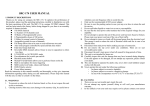
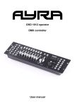
Product Overview (front)
1
2
21
17
3
10
9
11
12
14
15
13
5
6
18
23
7
16
8
Item
1
2
3
4
19
Button or Fader
Function
Scanner indicator LEDS
Indicates the fixtures currently selected
Scanner select buttons
Scene select buttons
4
Channel faders
5
Page A Indicator LED
6
8
Program button
Used to enter programming mode
12
13
LCD display window
Mode Indicator LEDS
Bank Up button
Bank Down button
14
Tap Display button
15
Blackout button
16
17
18
19
20
21
22
23
24
25
26
Midi/Rec button
Auto/Del button
Chase buttons
Speed fader
Fade-Time fader
Fog button
Strobe button
Override button
In manual mode, press to toggle between pages of control or to select both pages
simultaneously. Both LEDS on will allow control of both lower and upper range channel.
Used to activate Music mode and as the copy command during programming
Status window displays pertinent operational data
Provides operating mode status, (manual, music or auto)
Function button to traverse Scene/Steps in banks or chases
Function button to traverse Scene/Steps in banks or chases
This is a Tap-Sync during playback and during programming changes the DMX value
displayed in the LCD panel to percentages
Sets the shutter or dimmer value of all fixtures to “0” causing all light output to cease
Activates MIDI external control and also used to confirm the record/save process
Used to activate Auto mode and as the delete function key during programming
Chase memory 1 ~ 6
This will adjust the hold time of a scene or a step within a chase
Also considered a cross-fade, sets the interval time between two scenes in a chase
Built in Chauvet fog controller
Built in Chauvet strobe controller
Joystick
To control pan and tilt movement
FINE button
Sets joystick to control pan and tilt in 16 bit resolution (fixture must have this feature)
Mode button
DMX-55 User Manual
26
Represents Ch 1~8 range selected
Represents Ch 9~16 range selected
11
25
For adjusting DMX values, Ch 1~8 can be adjusted immediately after pressing the
respective scanner select button, Ch 9~16 after pressing the Page select button
Page select button
10
24
Universal bump buttons representing scene location for storage and selection
Page B Indicator LED
Music/Bank Copy button
22
Fixture selection
7
9
20
Switches operating modes
5
2006-01-11 11:59:07
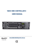
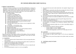
Connection Diagram (rear)
34
Item
27
28
29
30
31
32
33
34
35
27
28
29
35
30
Button or Fader
Function
DMX polarity switch
May be used to correct signal polarity
MIDI input port
DMX output connector
DC Input jack
Strobe connector
ON/OFF power switch
Fog connector
Audio input jack
DMX input connector
31
32
33
For external triggering of Banks and Chases using a MIDI device
DMX control signal
Main power feed
Chauvet Mono Strobe ¼” connector for built in strobe controller
Turns the controller on and off
Chauvet fog controller IEC connector
Audio input feed for music triggering
Used in data dumps between controllers
LCD Display Table of Definitions
Display Reference
SN1
BK1
CHASE1
STEP 009
DATA 184
SP :1M54s
TP:4.25s
ASS 04 05
RES 10 13
DMX-55 User Manual
Definition
Scene 1
Bank 1
Chase 1 is activated
Step # 9 of a chase
DMX Value (000-255)
The current speed is 1 minute 54 seconds
Sampled time between the last two taps
Assign DMX channels 4 and 5
Reverse DMX channels 10 and 13
6
2006-01-11 11:59:07
Introduction
Common Terms
The following are common terms used in intelligent light programming.
Blackout is a state by where all lighting fixtures light output are set to 0 or off, usually on a temporary
basis.
DMX-512 is an industry standard digital communication protocol used in entertainment lighting
equipment. For more information read Sections “DMX Primer” and “DMX Control Mode” in the
Appendix.
Fixture refers to your lighting instrument or other device such as a fogger or dimmer of which you can
control.
Programs are a bunch of scenes stacked one after another. It can be programmed as either a single
scene or multiple scenes in sequence.
Scenes are static lighting states.
Sliders also known as faders.
Chases can also be called programs. A chase consists of a bunch of scenes stacked one after
another.
Scanner refers to a lighting instrument with a pan and tilt mirror; however, in the ILS-CON controller it
can be used to control any DMX-512 compatible device as a generic fixture.
MIDI is a standard for representing musical information in a digital format. A MIDI input would provide
external triggering of scenes using midi device such as a midi keyboard.
Stand Alone refers to a fixture’s ability to function independently of an external controller and usually
in sync to music, due to a built in microphone.
Fade slider is used to adjust the time between scenes within a chase.
Speed slider affects the amount of time a scene will hold its state. It is also considered a wait time.
Shutter is a mechanical device in the lighting fixture that allows you to block the lights path. It is often
used to lessen the intensity of the light output and to strobe.
Patching refers to the process of assigning fixtures a DMX channel or.
Playbacks can be either scenes or chases that are directly called to execution by user action. A
playback can also be considered program memory that can be recalled during a show or running
mode.
DMX-55 User Manual
7
2006-01-11 11:59:07
OPERATING INSTRUCTIONS
Setup
S ET T ING U P T H E SY ST EM
1)
Place the DMX-55 on a leveled surface. Note! The DMX-55 can also be rack mounted,
occupying 3U spaces by removing the outer rubber edge guard.
2)
Plug the AC to DC power supply to the system back panel and to the mains outlet.
3)
Plug in your DMX cable(s) to your intelligent lighting as described in the fixtures respective
manual. For a quick Primer on DMX see the “DMX Primer” section in the Appendix of this
manual.
4)
Plug in a compatible Chauvet Fogger to the AC Fog Machine Remote Controller connector.
5)
Plug in any Chauvet MONO strobes in a daisy like fashion using a ¼” mono phone cable.
FI XT UR E P AT CH
The DMX-55 is programmed to control 16 channels of DMX per fixture, therefore the fixtures you wish
to control with the corresponding “SCANNER” buttons on the unit, must be spaced 16 channels apart.
FIXTURE OR
SCANNER #
1
2
3
4
5
6
7
8
9
10
11
12
DEFAULT DMX STARTING
ADDRESS
1
17
33
49
65
81
97
113
129
145
161
177
DIPSWITCH SETTINGS
SWITCH TO THE “ON POSITION”
1
1,5
1,6
1,5,6
1,7
1,5,7
1,6,7
1,5,6,7
1,8
1,5,8
1,6,8
1,5,6,8
Please refer to your individual fixture’s manual for DMX addressing instructions. The table above
refers to a standard 9 dipswitch binary configurable device.
DMX-55 User Manual
8
2006-01-11 11:59:07
Operating Instructions
JO Y ST ICK S ET UP
Because not all intelligent lighting fixtures are alike or share the same control attributes, the DMX-55
allows the user to assign the joystick the correct pan and tilt channel for every fixture.
Notes
Action
1)
Press the Program button until the LED
blinks.
2)
Hold the MODE button and press FINE.
The Reverse LED will light.
3)
Hold the MODE button again and press
FINE. The Assign LED will light.
4)
You will need to repeat this process to enter the
Assign Joystick Function.
Use BANK and BANK buttons to
select either Pan or Tilt.
5)
Use the TAP/Display button to switch
between the first 8 available channels
(8CH) and the second 8 (16CH).
6)
Press the button corresponding to the
SCANNER button you wish to assign.
7)
While holding the MODE button press
the scene number that corresponds to
the slider which controls the movement.
8)
Repeat steps 4 through 7 as necessary.
9)
To exit, hold the MODE button and
press FINE.
There are 16 available DMX channels but only 8 can
be selected at a time by using the SCENES buttons.
The TAP/Display acts like a page button allowing you
to have access to the lower 8 channels (8CH) and the
top 8 (16CH).
Example: If pan is controlled by slider number 4,
press and hold Mode button while pressing Scenes
button # 4.
Make sure Assign and Reverse LEDs are off.
RE V E R S E DM X C H AN NE L AN D JO Y ST IC K
Notes
Action
1)
Press the Program button until the LED
blinks.
2)
Hold the MODE button and press FINE.
The Reverse LED will light.
3)
DMX-55 User Manual
If the Reverse LED light does not light up repeat the
process until it does.
Use BANK and BANK buttons to
select either Pan or Tilt. The
corresponding LED will light.
4)
Use the TAP/Display button to switch
between the first 8 available channels
(8CH) and the second 8 (16CH).
5)
Press the button corresponding to the
SCANNER button you wish to assign.
6)
Find the slider or you wish to reverse
DMX output on.
7)
While holding the MODE button, press
the scene number that corresponds to
the slider you wish to reverse.
8)
Repeat steps 4 through 7 as necessary.
9)
To exit, hold the MODE button and
press FINE.
9
You may reverse a maximum of 48 channels for 12
scanners.
2006-01-11 11:59:07
Operating Instructions
DE L ET ING A S C AN N E R’ S DM X CH AN N E L S ET T ING S
Notes
Action
1)
Press the Program button until the LED
blinks.
2)
Hold the MODE button and press FINE.
The Reverse LED will light.
3)
Tap the Scanner button delete settings.
4)
Press the MODE and AUTO/Del
buttons at the same time. All LEDs will
flash three times to confirm operation.
Assign mode will also work in this case.
CL E AR AL L SC AN N E R’ S DM X CH AN N E L S
Notes
Action
1)
Turn the power off.
2)
Press and hold the MODE and
AUTO/Del buttons at the same time.
3)
Assign mode will also work in this case.
Turn the power back on. All LEDs will
flash briefly to confirm operation.
DI S PL AY P AN /T ILT D M X CH AN N E L S
Notes
Action
1)
Press the FINE and MODE buttons at
the same time putting the controller into
Assign mode.
Press the FINE and MODE buttons once
more to change to Reverse mode.
2)
Press the Scanner button that you wish
to display Pan and Tilt DMX values for.
F AD E T IM E SET T ING S
Notes
Action
1)
With power on the unit off, press the
MODE and TAP/Display buttons at the
same time.
2)
Apply power to the unit while holding
the buttons pressed above.
3)
Once unit is on, tap the TAP/Display
button to change between Fade Time
and Assign Fade Time.
Press the MODE and TAP/Display
buttons at the same time to store your
setting into memory.
4)
DMX-55 User Manual
You can also exit without saving by
pressing the Blackout button.
10
ALL
FD
CH
TIME
or
ONLY
FD
X/Y
TIME
2006-01-11 11:59:07
Operating Instructions
SC E N E P RO G R AM M ING
ENT ER ING PRO G R AM M ING M O DE
1)
Press the Program button until the LED blinks.
CR E AT E A S C E N E
A scene is a static lighting state. The DMX-55 can save 240 scenes.
Notes
Action
1)
Press the Program button until the LED
blinks.
2)
Position SPEED and FADE TIME
sliders all the way down.
3)
Select the SCANNERS you wish to
include in your scene.
You can select more than one fixture.
4)
Compose a look by moving the sliders
and joystick.
You can access channels 9~16 by pressing the Page
Select button. This is necessary for fixtures that use
more than 8 channels of control.
5)
Choose BANK.
There are 8 scenes available in every bank.
6)
Tap MIDI/Rec button.
7)
Select a SCENES button to store.
8)
Repeat steps 3 through 7 as necessary.
9)
To exit program mode, hold the MODE
button and press FINE.
Deselect Blackout if LED is lit.
-> All LEDs will flash three times to confirm. The
LED display will no indicate the Scene number and
Bank number used.
Shortcut: {Programming Fixtures} Press [Save] Select [Button 1~24] to store to memory
SC E N E E DIT
Notes
Action
1)
DMX-55 User Manual
Press the Program button until the LED
blinks.
2)
Use BANK and BANK buttons to
change banks.
3)
Tap the scene to edit within the bank.
4)
Follow steps 2 through 4 from “Create a
Scene”
5)
Tap MIDI/Rec button.
6)
Tap the same scene number originally
selected on step 3.
11
Deselect Blackout if LED is lit.
Remember this scene number!
Scene edit works by overriding a scene.
2006-01-11 11:59:07
Operating Instructions
CO PY SC AN N E R S ET T ING S
This operation allows the user to copy the programming state of one scanner to another. This is
especially useful when both scanners are of the same type.
Notes
Action
1)
Hold and maintain the Scanner button
to copy.
2)
Tap another Scanner button to copy
settings into.
CO PY SC E N E
Notes
Action
1)
Press the Program button until the LED
blinks.
2)
Use BANK and BANK buttons to
change banks.
3)
Tap the scene to copy within the bank.
4)
Use BANK and BANK buttons to
change to another bank if desired.
5)
Tap MIDI/Rec button.
6)
Tap the SCENES button you wish to
copy the scene to.
DE L ET E S C EN E
Notes
Action
1)
Press the Program button until the LED
blinks.
2)
Use BANK and BANK buttons to
change banks.
3)
Tap the scene to delete.
4)
Press and hold the Auto/Del button and
tap the scene button you wish to delete.
All DMX channels for the deleted scene will be set to
0.
DE L ET E AL L SC E N ES
Notes
Action
1)
Power off the controller.
2)
Press and hold the Program and BANK
buttons while turning the power back
on.
CO PY B AN K
Notes
Action
1)
2)
DMX-55 User Manual
Press the Program button until the LED
blinks.
Use BANK and BANK buttons to
select the bank to copy.
12
2006-01-11 11:59:07
Operating Instructions
3)
Tap the MIDI/Rec button.
4)
Use BANK and BANK buttons to
select the bank to copy to.
5)
Tap the Music/Bankcopy button to
execute the copy.
6)
To exit programming mode press the
Program button until the LED turns off.
All LEDs wil flash three times to confirm process.
Chase Programming
A chase is created by using previously created scenes. Scenes become steps in a chase and can be
arranged in any order you choose. It is highly recommended that prior to programming chases for the
first time; you delete all chases from memory. See “Delete All Chases” for instructions.
CR E AT E A C H AS E
A Chase can contain 240 scenes as steps. The term steps and scenes are used interchangeably.
Notes
Action
7)
Press the Program button until the LED
blinks.
8)
Tap the Chase button you wish to
program.
9)
Change BANK if necessary to locate a
scene.
10) Select the scene to insert.
11) Tap the MIDI/Rec button to store.
12) Repeat steps 3 ~ 5 to add additional
steps in the chase.
IN S ERT I NG A B AN K O F SC E N E S INT O A C H AS E
Notes
Action
1)
Pres the Program button until the LED
blinks.
2)
Tap the Chase button you wish to
program.
3)
DMX-55 User Manual
Use BANK and BANK buttons to
select the bank of scenes to copy.
4)
Tap the Music/Bankcopy button to
execute the copy.
5)
Tap the MIDI/Rec copy button to
confirm, all LEDs will flash three times.
13
2006-01-11 11:59:07
Operating Instructions
AD D A ST E P
Notes
Action
1)
Press the Program button until the LED
blinks.
2)
Press the corresponding button to the
chase you wish to add a step to.
3)
Press the TAP/Display button so that
the LCD display shows the current step.
4)
Use the BANK and BANK buttons
to scroll to the step you wish to add a
step after.
5)
Press the MIDI/REC button. The LCD
will display one step number higher than
previous.
6)
Tap the TAP/Display button again. The
LCD will now display the current chase,
scene and bank. Create a desired
scene and record it as a new step or
select a previously programmed scene
to add to the chase.
7)
Press the MIDI/REC button again. All
LEDs will flash three times to confirm
the save.
DE L ET E A ST E P
Notes
Action
1)
Press the Program button until the LED
blinks.
2)
Select the chase that contains the step
you want to delete.
3)
Press the TAP/Display button to
display the current step number.
4)
5)
Use the BANK and BANK buttons
to scroll to the step you wish to delete.
Tap the AUTO/Del button to delete the
step. All LEDs will flash three times to
confirm the deletion process.
DE L ET E A C H AS E
Notes
Action
DMX-55 User Manual
1)
Press and hold the Chase button you
want to delete.
2)
Then, press and hold the AUTO/Del
button until all LEDs flash three times.
14
2006-01-11 11:59:07
Operating Instructions
DE L ET E AL L C H AS E S
Notes
Action
1)
With the power off, press and hold the
AUTO/Del and BANK buttons.
2)
Turn controller back on and all chases
will be cleared.
Playback (Scenes)
M ANU AL R UN SC EN E
When power is first turned ON, the controller will be in manual scene mode.
Notes
Action
1)
Make sure neither Music nor Auto
LEDs are on.
2)
Select the program BANK that stores
the scene you want to run manually by
using the BANK UP/DOWN.
3)
Press the SCENE button to run.
If by chance you are in programming mode you can
also press and hold the PROGRAM button until the
Program LED goes off.
RU NN ING I N SO UN D- M O DE
Notes
Action
1)
Press the Music/Bankcopy button until
the Music LED turns on.
2)
Change BANK programs by using
BANK UP/DOWN buttons if necessary.
3)
Press the Music/Bankcopy to exit.
In the Sound mode, programs will be triggered by the
sound using its built-in microphone. All scenes in a
Bank will chase.
RU NN ING I N AU T O - M O D E
This mode allows you to run a bank of programmed scenes in sequence.
Notes
Action
1)
Press the AUTO/Del button until the
Auto LED turns on.
2)
Change BANK programs by using
BANK UP/DOWN buttons if necessary.
3)
You can adjust the time between steps
by moving the SPEED fader and the
duration of the step by moving the
FADE TIME fader.
CAUTION! The fade setting should never be slower
than the speed setting or the scene will never
complete execution.
4)
Use the TAP/Display button to set the
speed instead. The time between two
sequential taps sets the speed.
These settings will stay until the speed slider is
moved.
5)
Press the AUTO/Del button to exit
mode.
In the Auto mode, programs will be triggered by
controllers fade and speed time as set on the faders.
All scenes in a Bank will chase.
BL AC KO UT
The Blackout button brings all lighting output to 0 or off.
DMX-55 User Manual
15
2006-01-11 11:59:07
Operating Instructions
Playback (Chases)
M ANU AL R UN C H AS E S
This function allows the user to manually step through each individual step in a chase.
Notes
Action
1)
When the power is first turned on the
controller enters manual mode
automatically.
2)
Start a chase by pressing any one of
the Chase buttons.
3)
Press the Chase button again to
deselect.
AUT O R UN C H AS E S
Notes
Action
1)
Press the AUTO/Del button to activate
Auto mode. The Auto LED should light.
2)
Start a chase by pressing any one of
the Chase buttons.
3)
Pressing the Chase button again will
deselect it.
4)
Adjust the SPEED and FADE faders to
your liking.
CAUTION! The fade setting should never be slower
than the speed setting or the scene will never
complete execution.
M USIC R UN C H AS E S
Notes
Action
DMX-55 User Manual
1)
Press the MUSIC/Bankcopy button to
activate music mode.
2)
Start a chase by pressing any one of
the Chase buttons. The chase will
instantly respond to the music.
16
2006-01-11 11:59:07
Operating Instructions
Midi Operation
The controller will only respond to MIDI commands on the MIDI channel which it is set to full stop. All
MIDI control is performed using Note on commands. All other MIDI instructions are ignored. To stop a
chase, send the blackout on note.
Notes
Action
1)
Press and hold the MIDI/REC button for
about 3 seconds.
2)
Select the MIDI control channel (1~16)
via the BANK UP/DOWN buttons to set.
3)
Press and hold the MIDI/REC button for
3 seconds to save settings.
4)
To release MIDI control, press any other
button except the BANK buttons during
step 2.
MIDI NOTE
FUNCTION (TURN ON/OFF)
00 to 07
Scenes 1~8 in BANK 1
08 to 15
Scenes 1~8 in BANK 2
16 to 23
Scenes 1~8 in BANK 3
24 to 31
Scenes 1~8 in BANK 4
32 to 39
Scenes 1~8 in BANK 5
40 to 47
Scenes 1~8 in BANK 6
48 to 55
Scenes 1~8 in BANK 7
56 to 63
Scenes 1~8 in BANK 8
64 to 71
Scenes 1~8 in BANK 9
72 to 79
Scenes 1~8 in BANK 10
80 to 87
Scenes 1~8 in BANK 11
88 to 95
Scenes 1~8 in BANK 12
96 to 103
Scenes 1~8 in BANK 13
104 to 111
Scenes 1~8 in BANK 14
112 to 119
Scenes 1~8 in BANK 15
120
Chase 1
121
Chase 2
122
Chase 3
123
Chase 4
124
Chase 5
125
Chase 6
126
BLACKOUT
This is the Channel that the controller will receive
MIDI note commands.
Data Transfer
It is possible to transfer the programs stored in one DMX-55 controller to another. Connect from the
DMX output of the programmed controller to the DMX input of the other.
Notes
Action
DMX-55 User Manual
1)
Source unit: Turn unit Off, press and
hold SCANNER buttons 2, 3 and
SCENE button 1 then turn unit back On.
The display should show TRANSMIT, this indicates it
is ready to transmit data.
2)
Destination unit: Turn unit Off, press
and hold SCANNER buttons 8, 9 and
SCENE button 2 then turn unit back On.
The display should show RECEIVE, this indicates it is
ready to receive data transmission.
3)
Both units are now ready to transmit
and receive. Press SCENE buttons 7 &
8 simultaneously on Source unit to
begin transmission.
17
2006-01-11 11:59:07
APPENDIX
DMX Primer
There are 512 channels in a DMX-512 connection. Channels may be assigned in any manner. A
fixture capable of receiving DMX 512 will require one or a number of sequential channels. The user
must assign a starting address on the fixture that indicates the first channel reserved in the controller.
There are many different types of DMX controllable fixtures and they all may vary in the total number
of channels required. Choosing a start address should be planned in advance. Channels should
never overlap. If they do, this will result in erratic operation of the fixtures whose starting address is
set incorrectly. You can however, control multiple fixtures of the same type using the same starting
address as long as the intended result is that of unison movement or operation. In other words, the
fixtures will be slaved together and all respond exactly the same.
DMX fixtures are designed to receive data through a serial Daisy Chain. A Daisy Chain connection is
where the DATA OUT of one fixture connects to the DATA IN of the next fixture. The order in which
the fixtures are connected is not important and has no effect on how a controller communicates to
each fixture. Use an order that provides for the easiest and most direct cabling. Connect fixtures
using shielded two conductor twisted pair cable with three pin XLR male to female connectors. The
shield connection is pin 1, while pin 2 is Data Negative (S-) and pin 3 is Data positive (S+). CHAUVET
carries 3-pin XLR DMX compliant cables, DMX-10 (33’), DMX-4.5 (15’) and DMX-1.5 (5’)
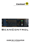
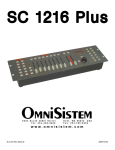
FI XT UR E LI NK ING
Figure 1 - DMX connector configuration
1
3
2
COMMON
INPUT
Note!
1
3
2
1
3
2
DMX +
Resistance 120
ohm 1/4w between
pin 2 (DMX -) and
pin 3 (DMX +) of
the last fixture.
OUTPUT
DMX -
Termination reduces signal errors and to
avoid signal transmission problems and
interference, it is always advisable to connect
a DMX signal terminator.
If you use a controller with a 5 pin DMX output connector, you will need to use a 5
pin to 3 pin adapter. Chauvet Model No: DMX5M.
The chart below details a proper cable conversion:
3 PIN TO 5 PIN CONVERSION CHART
CONDUCTOR
3 Pin Female (output)
5 Pin Male (Input)
GROUND/SHIELD
Pin 1
Pin 1
DATA ( - )SIGNAL
Pin 2
Pin 2
DATA ( + ) SIGNAL
Pin 3
Pin 3
DO NOT USE
Do not use
DO NOT USE
Do not use
DMX-55 User Manual
18
2006-01-11 11:59:07
Appendix
Maintenance
To maintain optimum performance and minimize wear fixtures should be cleaned frequently. Usage
and environment are contributing factors in determining frequency. As a general rule, fixtures should
be cleaned at least twice a month. Dust build up reduces light output performance and can cause
overheating. This can lead to reduced lamp life and increased mechanical wear. Be sure to power off
fixture before conducting maintenance.
Unplug fixture from power. Use a vacuum or air compressor and a soft brush to remove dust
collected on external vents and internal components. Clean all glass when the fixture is cold with a
mild solution of glass cleaner or Isopropyl Alcohol and a soft lint free cotton cloth or lens tissue. Apply
solution to the cloth or tissue and drag dirt and grime to the outside of the lens. Gently polish optical
surfaces until they are free of haze and lint. Do not to touch the lamp glass when cleaning fixture. Oil
and dirt can cause damage and premature aging of the lamp. In the event that the lamp is touched or
becomes dirty, clean the lamps with an alcohol wipe.
The cleaning of internal and external optical lenses and/or mirrors must be carried out periodically to
optimize light output. Cleaning frequency depends on the environment in which the fixture operates:
damp, smoky or particularly dirty surrounding can cause greater accumulation of dirt on the unit’s
optics. Clean with soft cloth using normal glass cleaning fluid. - Always dry the parts carefully. - Clean
the external optics at least every 20 days. Clean the internal optics at least every 30/60 days.
Returns Procedure
Returned merchandise must be sent prepaid and in the original packing, call tags will not be issued.
Package must be clearly labeled with a Return Merchandise Authorization Number (RA #). Products
returned without an RA # will be refused. Call CHAUVET and request RA # prior to shipping the
fixture. Be prepared to provide the model number, serial number and a brief description of the cause
for the return. Be sure to properly pack fixture, any shipping damage resulting from inadequate
packaging is the customer’s responsibility. CHAUVET reserves the right to use its own discretion to
repair or replace product(s). As a suggestion, proper UPS packing or double-boxing is always a safe
method to use.
Claims
Damage incurred in shipping is the responsibility of the shipper; therefore the damage must be
reported to the carrier upon receipt of merchandise. It is the customer's responsibility to notify and
submit claims with the shipper in the event that a fixture is damaged due to shipping. Any other claim
for items such as missing component/part, damage not related to shipping, and concealed damage,
must be made within seven (7) days of receiving merchandise.
DMX-55 User Manual
19
2006-01-11 11:59:07
Appendix
General Troubleshooting
Applies to
Symptom
Solution(s)
Auto shut off
Check fan thermal switch reset
Beam is very dim or not
bright
Clean optical system or replace lamp
Breaker/Fuse keeps
blowing
Check total load placed on device
Chase is too slow
Check users manual for speed adjustment
Device has no power
Check for power on Mains.
Lights
Foggers
& Snow
Controllers
Dimmers
& Chaser
Check 220/110v switch for proper setting
Check device’s fuse. (internal and/or external)
Fixture is not
responding
Check DMX Dip switch settings for correct addressing
Check DMX cables
Check polarity switch settings
Fixture is on but there
is no movement to the
audio
Make sure you have the correct audio mode on the control
switches. If audio provided via ¼” jack, make sure a live
audio signal exists
Adjust sound sensitivity knob
Lamps cuts off
sporadically
Possible bad lamp or fixture is overheating.
Light will not come on
after power failure
Some discharge lamps require a cooling off period before
the electronics in the fixture can kick start it again, wait 5 to
10 minutes before powering up
Loss of signal
Use only DMX cables
Lamp may be at end of its life.
Install terminator
Note: Keep DMX cables separated from power cables or
black lights.
Moves slow
Check 220/110v switch for proper setting
No flash
Re-install bulb, may have shifted in shipping
No laser output
Bounce mirror motor may have shifted during shipping,
readjust
No light output
Check slip ring & brushes for contact
Install bulb
Call service technician
Relay will not work
Check reset switch
Check cable connections
Remote does not work
Make sure connector is firmly connected to device
Stand alone mode
All Chauvet lighting fixtures featuring stand-alone functions
do not require additional settings, simply power the fixture
and it will automatically enter into this mode
DMX-55 User Manual
20
2006-01-11 11:59:07
Appendix
Technical Specifications
WEIGHT & DIMENSIONS
Length...................................................................................................................... 514 mm (20.25 in)
Width..............................................................................................................................89 mm (3.5 in)
Height ........................................................................................................................ 171 mm (6.75 in)
Weight............................................................................................................................ 2.7 Kg (6 lbs)
POWER
Operating Range.............................................................................................. DC 9V-12V 500mA min
Adapter ...................................................................................................................................Provided
THERMAL
Maximum ambient temperature ....................................................................................... 45°C (113° F)
CONTROL & PROGRAMMING
Data input ............................................................................................. locking 3-pin XLR male socket
Data output ...................................................................................2 x locking 3-pin XLR female socket
Data pin configuration ............................................................................pin 1 shield, pin 2 (-), pin 3 (+)
Protocols.....................................................................................................................DMX-512 USITT
ORDERING INFORMATION
DMX-55 DMX Controller...........................................................................................................DMX-55
EC DECLARATION OF CONFORMITY
We declare that our products (lighting equipments) comply with the following specification and bears
CE mark in accordance with the provision of the Electromagnetic Compatibility (EMC) Directive
89/336/EEC.
.................................................................EN55014-1: 1993, EN61000-3-2: 1995, EN61000-3-3:1995
......................................................................................................... EN55014-2: 1997 CATEGORY II
..............................................................EN61000-4-2: 1995, EN61000-4-3: 1995, EN61000-4-4:1995
...........................................................EN61000-4-5: 1995, EN61000-4-6: 1995, EN61000-4-11: 1994
Harmonized Standard ............................................................................................... EN60598-1: 1993
Safety of household and similar electrical appliances Part 1: General requirements
Following the provisions of the Low Voltage Directive 73/23/EEC and 93/68/EEC.
EC DECLARATION OF CONFORMITY
We declare that our products (remote controller) comply with the following specification and bears CE
mark in accordance with the provision of the Electromagnetic Compatibility (EMC) Directive
89/336/EEC.
.................................................................................................................................... EN55015: 1993
................................................................................................................................. EN50082-1: 1997
.............................................................................................................................. EN61000-3-2: 1995
.............................................................................................................................. EN61000-3-3: 1995
DMX-55 User Manual
21
2006-01-11 11:59:07