1
DMX-4
Dimmer/Relay Pack
USER MANUAL
Chauvet, 3000 N 29th Ct, Hollywood, FL 33020 U.S.A
(800) 762-1084 – (954) 929-1115
FAX (954) 929-5560
www.chauvetlighting.com
Table of Contents
BEFORE YOU BEGIN .................................................................................................................... 3
W HAT IS INCLUDED ........................................................................................................................ 3
UNPACKING INSTRUCTIONS ............................................................................................................ 3
AC POWER ................................................................................................................................... 3
SAFETY INSTRUCTIONS .................................................................................................................. 3
INTRODUCTION ............................................................................................................................. 4
FEATURES..................................................................................................................................... 4
DMX CHANNEL SUMMARY ............................................................................................................. 4
PRODUCT OVERVIEW ..................................................................................................................... 4
SETUP............................................................................................................................................. 5
POWER ......................................................................................................................................... 5
MOUNTING .................................................................................................................................... 5
Orientation ........................................................................................................................................ 5
Rigging ............................................................................................................................................. 5
OPERATING INSTRUCTIONS ....................................................................................................... 6
MENU NAVIGATION ........................................................................................................................ 6
OPERATING MODES ....................................................................................................................... 6
Running in Chase Mode ......................................................................................................... 6
Select Pattern Chase........................................................................................................................ 6
Adjust the Speed .............................................................................................................................. 6
Adjust Intensity ................................................................................................................................. 6
Running in DMX Mode............................................................................................................ 7
Select DMX Mode & Set Starting Address........................................................................................ 7
Optional Dimmer/Relay Setting ........................................................................................................ 7
DMX Control Channel Modes ........................................................................................................... 7
REPLACING A FUSE ........................................................................................................................ 7
APPENDIX ...................................................................................................................................... 8
DMX PRIMER ................................................................................................................................ 8
Fixture Linking .................................................................................................................................. 8
DMX CHANNEL VALUES................................................................................................................. 9
MAINTENANCE ............................................................................................................................... 9
RETURNS PROCEDURE .................................................................................................................. 9
CLAIMS ......................................................................................................................................... 9
GENERAL TROUBLESHOOTING ...................................................................................................... 10
TECHNICAL SPECIFICATIONS ........................................................................................................ 11
DMX-4 User Manual
2
BEFORE YOU BEGIN
What is included
DMX-4 Dimmer/Relay Pack
Detachable power cord (IEC 60320 C-13)
Warranty Card
Unpacking Instructions
Immediately upon receiving a fixture, carefully unpack the carton, check the contents to ensure that
all parts are present, and have been received in good condition. Notify the shipper immediately and
retain packing material for inspection if any parts appear damaged from shipping or the carton itself
shows signs of mishandling. Save the carton and all packing materials. In the event that a fixture
must be returned to the factory, it is important that the fixture be returned in the original factory box
and packing.
AC Power
To determine the power requirements for a particular fixture, see the label affixed to the back plate of
the fixture or refer to the fixture’s specifications chart. A fixture’s listed current rating is its average
current draw under normal conditions. All fixtures must be powered directly off a switched circuit and
cannot be run off a rheostat (variable resistor) or dimmer circuit, even if the
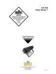
Figure 1 - AC Voltage Switch
rheostat or dimmer channel is used solely for a 0% to 100% switch. Before
applying power to a fixture, check that the source voltage matches the
fixture’s requirement. Check the fixture or device carefully to make sure that
if a voltage selection switch exists that it is set to the correct line voltage
you will use.
Warning!
Verify that the power select switch on your unit matches the line voltage applied. All
fixtures must be connected to circuits with a suitable Earth Ground.
Safety Instructions
Please read these instructions carefully, which includes important
information about the installation, usage and maintenance?
•
•
•
•
•
•
•
Please keep this User Guide for future consultation. If you
sell the unit to another user, be sure that they also receive
this instruction booklet.
Always make sure that you are connecting to the proper
voltage and that the line voltage you are connecting to is
not higher than that stated on decal or rear panel of the
fixture.
This product is intended for indoor use only!
To prevent risk of fire or shock, do not expose fixture to
rain or moisture. Make sure there are no flammable
materials close to the unit while operating.
The unit must be installed in a location with adequate
ventilation, at least 50cm from adjacent surfaces. Be sure
that no ventilation slots are blocked.
Always disconnect from power source before servicing or
replacing lamp or fuse and be sure to replace with same
lamp source.
Caution!
•
•
•
•
•
•
Secure fixture to fastening device using a safety chain.
Never carry the fixture solely by its head. Use its carrying
handles.
Maximum ambient temperature is Ta: 40°. Do not operate
fixture at temperatures higher than this.
In the event of serious operating problem, stop using the
unit immediately. Never try to repair the unit by yourself.
Repairs carried out by unskilled people can lead to
damage or malfunction. Please contact the nearest
authorized technical assistance center. Always use the
same type spare parts.
Don’t connect the device to a dimmer pack.
Make sure power cord is never crimped or damaged.
Never disconnect power cord by pulling or tugging on the
cord.
Avoid direct eye exposure to lamp while it is on.
There are no user serviceable parts inside the unit. Do not open the housing or
attempt any repairs yourself. In the unlikely event your unit may require service,
please contact CHAUVET.
DMX-4 User Manual
3
INTRODUCTION
Features
•
•
•
•
•
•
•
•
universal DMX-512 Dimmer/Relay Pack
4 channels of DMX
set to dimmer or relay
easy to read LED segment display
built in stand alone chase patterns
adjustable chase speed
switch-selectable power settings 115V or 230V, (240V version available)
2 year warranty
DMX Channel Summary
CHANNEL
FUNCTION
1
Dimmer or Switch
2
Dimmer or Switch
3
Dimmer or Switch
4
Dimmer or Switch
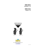
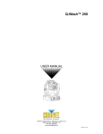
Product Overview
Output
Hanging Bracket
10 Amps 115V/Ch, 20A max load
5 Amps 230V/Ch, 10A max load
Six holes provide different positions for
mounting a pipe clamp
Button Reference
This is a quick reference
of button functions and
what they display.
LED Indicator
4 LED channel activity
indicators
Power Switch
LED Segment
On/Off switch
Displays current activity
or function state
Menu Buttons
Displays current activity
or function state
Power Input
Voltage Selector
Fuses
DMX In
DMX Out
Supplied with IEC 60320 C-14
receptacle for detachable
power cord
Select either 115V or
230V operation
20mm Glass 10A 125V
20mm Glass 6.3A 250V
Locking 3-pin XLR male
socket
Locking 3-pin XLR
female socket
DMX-4 User Manual
4
SETUP
Power
Your product is equipped with switch-selectable AC power
setting.
Warning!
Slide switch up or down
depending on your line voltage.
Verify that the power select switch on your unit
matches the line voltage applied. All fixtures must be
connected to circuits with a suitable Earth Ground.
•
•
•
•
•
To determine the power requirements for a particular fixture, see the label
affixed to the back plate of the fixture or refer to the fixture’s specifications chart.
A fixture’s listed current rating is its average current draw under normal conditions.
All fixtures must be powered directly off a switched circuit and cannot be run off a rheostat (variable
resistor) or dimmer circuit, even if the rheostat or dimmer channel is used solely for a 0% to 100%
switch.
Before applying power to a fixture, check that the source voltage matches the fixture’s requirement.
All fixtures must be connected to circuits with a suitable Earth Ground.
Mounting
O RI E NT AT IO N
This fixture may be mounted in any position provided there is adequate room for ventilation. It is also
possible to stand this fixture using the removable feet provided.
RIG G ING
Figure 2 - Hanging Clamp
It is important never to obstruct the fan or vents pathway. Mount the
fixture using, a suitable “C” or “O” type clamp. Adjust the angle of the
fixture by loosening both knobs and tilting the fixture. After finding the
desired position, retighten both knobs.
•
•
•
When selecting installation location, take into consideration lamp
replacement access and routine maintenance.
Safety cables should always be used.
Never mount in places where the fixture will be exposed to rain, high
humidity, extreme temperature changes or restricted ventilation.
DMX-4 User Manual
5
Note!
Clamp is sold separately.
OPERATING INSTRUCTIONS
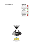
Menu Navigation
MODE
A001~512
DMX Mode
P:01~16
CHASE Mode
MENU
MENU
A001 ~ A512
DMX Addressing
P:01 ~ P:16
Pattern Chase Select
CH:01 ~ CH:04
Control Channel Mode
SP:01 ~ SP:99
Chase Speed Select
S – oF / S – on
Relay/Dimmer Switch
d000 ~ d100
Dimmer Output Level
Operating Modes
The DMX-4 can be controlled using any universal DMX-512 controller. There are also 16 preset
chase programs that a user can select for stand alone operation (Chase Mode).
Running in Chase Mode
S EL E CT P AT T E RN C H AS E
1)
Press the MODE button until the display reads {P:nn}, where n represents a number between 01
and 16.
2)
Press the (
patterns.
Button) and (
Button) to increase or decrease values representing chase
AD J U ST T H E S P E ED
1)
Press the MODE button until the display reads {P:nn}, where n represents a number between 01
and 16.
2)
Press the MENU button until the display reads {SP:nn}, where n represents a number between
01 and 99.
3)
Press the (
achieved.
Button) and (
Button) to increase or decrease values until the desired speed is
AD J U ST I NT E N SIT Y
1)
Press the MODE button until the display reads {P:nn}, where n represents a number between 01
and 16.
2)
Press the MENU button until the display reads {dnnn}, where n represents a number between
000 and 100.
3)
Press the ( Button) and (
is achieved.
DMX-4 User Manual
Button) to increase or decrease values until the desired intensity
6
Running in DMX Mode
This DMX mode enables the use of a universal DMX controller device. Each fixture requires a "start
address" that can be set from 001 to 512. A fixture requiring one or more channels for control begins
to read the data on the channel indicated by the start address. For example, a fixture that occupies or
uses 6 channels of DMX and was addressed to start on DMX channel 100, would read data from
channels: 100, 101, 102, 103, 104, and 105. Choose start addresses so that the channels used do
not overlap and notate the start address selected for future reference.
If this is your first time addressing a fixture using the DMX-512 control protocol than I suggest jumping
to the Appendix Section and read the heading “DMX Primer”. It contains very useful information that
will help you understand its use.
S EL E CT DM X M O DE & S ET ST ART ING AD DR E S S
1)
Press the MODE button until the display reads {Annn}, where n represents a number between
001 and 512.
2)
Press the ( Button) and ( Button) to increase or decrease values until the desired DMX
starting address is achieved.
O PT IO N AL D IM M ER/ R EL AY S ET T ING
1)
Press the MODE button until the display reads {Annn}, where n represents a number between
001 and 512.
2)
Press the MENU button until the display reads {S-nn}, where nn represents either (oF) for
switching off or (oN) for switching on.
3)
Press the (
Button) and (
Button) to toggle between {S-oN} and {S-oF}.
DM X CO NT RO L C H AN NE L M O D ES
1)
Press the MODE button until the display reads {Annn}, where n represents a number between
001 and 512.
2)
Press the MENU button until the display reads {CH:nn}, where n represents a number between
01 and 04.
3)
Press the ( Button) and (
channel output
Button) to increase or decrease values to select a desired
SELECTION
BEHAVIOR
CH:01
DMX channel 1 will control outputs (1 through 4 combined)
CH:02
DMX channel 1 will control outputs (1 and 2 combined)
DMX channel 2 will control outputs (3 and 4 combined)
CH:04
DMX channels 1 through 4 will control outputs 1 through 4 respectively
Replacing a fuse
Disconnect the power cord before replacing a fuse and always
replace with the same type fuse.
With a Philips head screwdriver unscrew the
fuse holder until it can be entirely removed.
Remove the damaged fuse from its holder and
replace with exact same type fuse. Insert the
fuse holder back in its place and reconnect
power.
DMX-4 User Manual
7
FUSES: F10A 125V 5 X20mm
1
2
3
4
APPENDIX
DMX Primer
There are 512 channels in a DMX-512 connection. Channels may be assigned in any manner. A
fixture capable of receiving DMX 512 will require one or a number of sequential channels. The user
must assign a starting address on the fixture that indicates the first channel reserved in the controller.
There are many different types of DMX controllable fixtures and they all may vary in the total number
of channels required. Choosing a start address should be planned in advance. Channels should
never overlap. If they do, this will result in erratic operation of the fixtures whose starting address is
set incorrectly. You can however, control multiple fixtures of the same type using the same starting
address as long as the intended result is that of unison movement or operation. In other words, the
fixtures will be slaved together and all respond exactly the same.
DMX fixtures are designed to receive data through a serial Daisy Chain. A Daisy Chain connection is
where the DATA OUT of one fixture connects to the DATA IN of the next fixture. The order in which
the fixtures are connected is not important and has no effect on how a controller communicates to
each fixture. Use an order that provides for the easiest and most direct cabling. Connect fixtures
using shielded two conductor twisted pair cable with three pin XLR male to female connectors. The
shield connection is pin 1, while pin 2 is Data Negative (S-) and pin 3 is Data positive (S+). CHAUVET
carries 3-pin XLR DMX compliant cables, DMX-10 (33’), DMX-4.5 (15’) and DMX-1.5 (5’)
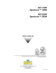
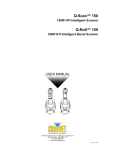
F I XT UR E L I NK ING
Figure 3 - DMX connector configuration
1
3
2
COMMON
INPUT
Note!
1
3
2
1
3
2
DMX +
Resistance 120
ohm 1/4w between
pin 2 (DMX -) and
pin 3 (DMX +) of
the last fixture.
OUTPUT
DMX -
Termination reduces signal errors and to
avoid signal transmission problems and
interference, it is always advisable to connect
a DMX signal terminator.
If you use a controller with a 5 pin DMX output connector, you will need to use a 5
pin to 3 pin adapter. Chauvet Model No: DMX5M.
The chart below details a proper cable conversion:
3 PIN TO 5 PIN CONVERSION CHART
CONDUCTOR
3 Pin Female (output)
5 Pin Male (Input)
GROUND/SHIELD
Pin 1
Pin 1
DATA ( - )SIGNAL
Pin 2
Pin 2
DATA ( + ) SIGNAL
Pin 3
Pin 3
DO NOT USE
Do not use
DO NOT USE
Do not use
DMX-4 User Manual
8
DMX Channel Values
Channel
Function
Dimmer or Switch
Value
1
000
255
Off > Full Intensity/On
2
000
255
Off > Full Intensity/On
3
000
255
Off > Full Intensity/On
4
000
255
Off > Full Intensity/On
Maintenance
To maintain optimum performance and minimize wear fixtures should be cleaned frequently. Usage
and environment are contributing factors in determining frequency. As a general rule, fixtures should
be cleaned at least twice a month.
Unplug fixture from power. Use a vacuum or air compressor and a soft brush to remove dust
collected on external vents and internal components.
Returns Procedure
Returned merchandise must be sent prepaid and in the original packing, call tags will not be issued.
Package must be clearly labeled with a Return Merchandise Authorization Number (RA #). Products
returned without an RA # will be refused. Call CHAUVET and request RA # prior to shipping the
fixture. Be prepared to provide the model number, serial number and a brief description of the cause
for the return. Be sure to properly pack fixture, any shipping damage resulting from inadequate
packaging is the customer’s responsibility. CHAUVET reserves the right to use its own discretion to
repair or replace product(s). As a suggestion, proper UPS packing or double-boxing is always a safe
method to use.
Claims
Damage incurred in shipping is the responsibility of the shipper; therefore the damage must be
reported to the carrier upon receipt of merchandise. It is the customer's responsibility to notify and
submit claims with the shipper in the event that a fixture is damaged due to shipping. Any other claim
for items such as missing component/part, damage not related to shipping, and concealed damage,
must be made within seven (7) days of receiving merchandise.
DMX-4 User Manual
9
General Troubleshooting
Applies to
Symptom
Solution(s)
Auto shut off
Check fan thermal switch reset
Beam is very dim or not
bright
Clean optical system or replace lamp
Breaker/Fuse keeps
blowing
Check total load placed on device
Chase is too slow
Check users manual for speed adjustment
Device has no power
Check for power on Mains.
Lights
Check 220/110v switch for proper setting
Check device’s fuse. (internal and/or external)
Fixture is not responding
Check DMX Dip switch settings for correct addressing
Check DMX cables
Check polarity switch settings
Fixture is on but there is
no movement to the audio
Make sure you have the correct audio mode on the control switches.
If audio provided via ¼” jack, make sure a live audio signal exists
Adjust sound sensitivity knob
Lamps cuts off
sporadically
Possible bad lamp or fixture is overheating.
Light will not come on after
power failure
Some discharge lamps require a cooling off period before the
electronics in the fixture can kick start it again, wait 5 to 10 minutes
before powering up
Loss of signal
Use only DMX cables
Lamp may be at end of its life.
Install terminator
Note: Keep DMX cables separated from power cables or black lights.
Motor movements are
jerky or jumpy
Possible bad motor driver or sensors
Moves slow
Check 220/110v switch for proper setting
No flash
Re-install bulb, may have shifted in shipping
No light output
Check slip ring & brushes for contact
Check polarity switch on controller
Install bulb
Call service technician
Relay will not work
Check reset switch
Check cable connections
Remote does not work
Make sure connector is firmly connected to device
Stand alone mode
All Chauvet lighting fixtures featuring stand-alone functions do not
require additional settings, simply power the fixture and it will
automatically enter into this mode
Unit wobbles when rotating
Check for damages possibly incurred during shipping
DMX-4 User Manual
10
Foggers
& Snow
Controllers
Dimmers
& Chaser
Technical Specifications
WEIGHT & DIMENSIONS
Length........................................................................................................................ 210 mm (8.25 in)
Width.......................................................................................................................... 194 mm (7.65 in)
Height .......................................................................................................................... 70 mm (2.75 in)
Weight..............................................................................................................................2.3 Kg (5 lbs)
POWER
Switch-selectable power setting ..................................................................115V 60 Hz or 230V 50 Hz
European version ............................................................................................................... 240V 50 Hz
AC input .......................................................................................................... 3-prong IEC 60320 C14
AC outputs ...............................................................................................(8) NEMA 5-15R receptacles
AC output (115V) ............................................................................................. 10A/Channel, Max 20A
AC output (230V) ............................................................................................... 5A/Channel, Max 10A
FUSE
Main (115V) ................................................................................(4) 20mm Glass 10A 125V Fast Blow
Main (230V) ............................................................................... (4) 20mm Glass 6.3A 250V Fast Blow
CONTROL & PROGRAMMING
Data input ............................................................................................. locking 3-pin XLR male socket
Data output ........................................................................................ locking 3-pin XLR female socket
Data pin configuration ............................................................................pin 1 shield, pin 2 (-), pin 3 (+)
Protocols.....................................................................................................................DMX-512 USITT
DMX Channels (Mode CH:04).............................................................................................................4
DMX Channels (Mode CH:02).............................................................................................................2
DMX Channels (Mode CH:01).............................................................................................................1
ORDERING INFORMATION
Dimmer/Relay Pack ...................................................................................................................DMX-4
Fuse 10A ...................................................................................................................... P170FUSE010
Fuse 6.3A ..................................................................................................................... P170FUSE007
DMX-4 User Manual
11