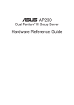
1
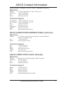
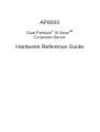
AP8000
®
Dual Pentium III XeonTM
Corporate Server
Hardware Reference Guide
User's Notice
No part of this manual, including the products and software described in it, may be reproduced, transmitted, transcribed, stored in a retrieval system, or translated into any language
in any form or by any means, except documentation kept by the purchaser for backup purposes, without the express written permission of ASUSTeK COMPUTER INC. (“ASUS”).
ASUS PROVIDES THIS MANUAL “AS IS” WITHOUT WARRANTY OF ANY KIND,
EITHER EXPRESS OR IMPLIED, INCLUDING BUT NOT LIMITED TO THE IMPLIED
WARRANTIES OR CONDITIONS OF MERCHANTABILITY OR FITNESS FOR A PARTICULAR PURPOSE. IN NO EVENT SHALL ASUS, ITS DIRECTORS, OFFICERS,
EMPLOYEES OR AGENTS BE LIABLE FOR ANY INDIRECT, SPECIAL, INCIDENTAL, OR CONSEQUENTIAL DAMAGES (INCLUDING DAMAGES FOR LOSS OF
PROFITS, LOSS OF BUSINESS, LOSS OF USE OR DATA, INTERRUPTION OF BUSINESS AND THE LIKE), EVEN IF ASUS HAS BEEN ADVISED OF THE POSSIBILITY
OF SUCH DAMAGES ARISING FROM ANY DEFECT OR ERROR IN THIS MANUAL
OR PRODUCT.
Product warranty or service will not be extended if: (1) the product is repaired, modified or
altered, unless such repair, modification of alteration is authorized in writing by ASUS; or
(2) the serial number of the product is defaced or missing.
Products and corporate names appearing in this manual may or may not be registered trademarks or copyrights of their respective companies, and are used only for identification or
explanation and to the owners’ benefit, without intent to infringe.
The product name and revision number are both printed on the product itself. Manual revisions are released for each product design represented by the digit before and after the
period of the manual revision number. Manual updates are represented by the third digit in
the manual revision number.
For previous or updated manuals, BIOS, drivers, or product release information, contact ASUS at http://www.asus.com.tw or through any of the means indicated on the
following page.
SPECIFICATIONS AND INFORMATION CONTAINED IN THIS MANUAL ARE FURNISHED FOR INFORMATIONAL USE ONLY, AND ARE SUBJECT TO CHANGE AT
ANY TIME WITHOUT NOTICE, AND SHOULD NOT BE CONSTRUED AS A COMMITMENT BY ASUS. ASUS ASSUMES NO RESPONSIBILITY OR LIABILITY FOR
ANY ERRORS OR INACCURACIES THAT MAY APPEAR IN THIS MANUAL, INCLUDING THE PRODUCTS AND SOFTWARE DESCRIBED IN IT.
Copyright © 1999 ASUSTeK COMPUTER INC. All Rights Reserved.
Product Name:
Manual Revision:
Release Date:
2
AP8000
1.01 E398
June 1999
AP8000 Hardware Reference Guide
ASUS Contact Information
ASUSTeK COMPUTER INC. (Asia-Pacific)
Marketing
Address:
Telephone:
Fax:
Email:
150 Li-Te Road, Peitou, Taipei, Taiwan 112
+886-2-2894-3447
+886-2-2894-3449
[email protected]
Technical Support
Tel (English):
Tel (Chinese):
Fax:
Email:
Newsgroup:
WWW:
FTP:
+886-2-2894-3447 ext. 706
+886-2-2894-3447 ext. 701
+886-2-2895-9254
[email protected]
news2.asus.com.tw
www.asus.com.tw
ftp.asus.com.tw/pub/ASUS
ASUS COMPUTER INTERNATIONAL (America)
Marketing
Address:
Fax:
Email:
6737 Mowry Avenue, Mowry Business Center, Building 2
Newark, CA 94560, USA
+1-510-608-4555
[email protected]
Technical Support
Fax:
BBS:
Email:
WWW:
FTP:
+1-510-608-4555
+1-510-739-3774
[email protected]
www.asus.com
ftp.asus.com.tw/pub/ASUS
ASUS COMPUTER GmbH (Europe)
Marketing
Address:
Telephone:
Fax:
Email:
Harkort Str. 25, 40880 Ratingen, BRD, Germany
49-2102-445011
49-2102-442066
[email protected]
Technical Support
Hotline:
BBS:
Email:
WWW:
FTP:
49-2102-499712
49-2102-448690
[email protected]
www.asuscom.de
ftp.asuscom.de/pub/ASUSCOM
AP8000 Hardware Reference Guide
3
Contents
I. Introduction
1-1. How this Manual is Organized .......................................... 7
Symbols ........................................................................ 7
1-2. Component Checklist ........................................................ 8
Standard Components .................................................. 8
Optional Components ................................................... 8
1-3. Features ............................................................................ 9
1-4. Safeguards ..................................................................... 10
Operation Safety ......................................................... 10
Tools Required ............................................................ 10
1-5. Electrical Safety ...............................................................11
Static-Sensitive Devices ............................................. 11
II. Components
2-1. Server Front Side ............................................................ 13
2-2. Server Back Side ............................................................ 14
2-3. Server Left Side .............................................................. 15
III. Basic Operation
3-1. Starting the Server .......................................................... 16
3-2. LED Indicators ................................................................ 16
3-3. BIOS Setup ..................................................................... 16
IV. Hardware Setup
4-1. Opening the Chassis ...................................................... 17
Chassis Panels ........................................................... 17
Opening the Left Panel ............................................... 17
Fan Replacement ....................................................... 17
4-2. Motherboard ................................................................... 18
Motherboard Spacers ................................................. 18
Install the Baseboard .................................................. 18
Motherboard Screws ................................................... 18
Device Cables ............................................................. 19
Cable Connections ..................................................... 19
4-3. Central Processing Unit (CPU) ....................................... 20
Install Retention Mechanisms ..................................... 20
Install Retention Mechanism Brace Bars .................... 20
Install Cartridge Lifters ................................................ 21
Install Retention Mechanism Cap ............................... 21
Install Retention Mechanism Frame ........................... 21
4-4. Chassis Intrusion Switch ................................................. 22
Chassis Intrusion Connector ....................................... 23
4-5. Expansion Cards ............................................................ 23
4-6. Fixed Storage Devices .................................................... 24
4
AP8000 Hardware Reference Guide
Contents
Fixed Storage Device Tray ......................................... 24
Fixed Device Bay Cover Clips .................................... 24
Fixed Device Bay Cover ............................................. 24
4-7. Floppy Disk Drive and CD-ROM ..................................... 25
Floppy Disk Drive ........................................................ 25
CD-ROM Drive ............................................................ 25
4-8. Hot-Swap Trays .............................................................. 26
Removing Hot-Swap Trays ......................................... 26
Hot-Swap Tray Usage ................................................. 26
Hot-Swap Tray Front Connections .............................. 27
Hot-Swap Tray Interface ............................................. 27
4-9. Hot-Swap Tray Connector Board .................................... 28
Hot-Swap Tray Rear Connections .............................. 28
4-10. SCSI Backplane ............................................................ 29
4-11. SCSI ID Setting ............................................................. 30
Using the SCSI Backplane Boards Separately ........... 30
Using Cascaded SCSI Backplane Boards .................. 31
4-12. SCSI Backplane Board Placement ............................... 32
Installing & Removing SCSI Backplane Boards ......... 32
SCSI Hard Disk Connections ...................................... 33
4-13. Circulation System ........................................................ 34
Fan Module ................................................................. 34
Fan Replacement ....................................................... 34
4-14. Power Supply ................................................................ 35
Redundant Power Supply ........................................... 35
Power Supply Mounting .............................................. 35
Removing One Power Supply Module ........................ 35
Removing the Entire Power Supply Unit ..................... 36
Power Module Rating ................................................. 37
Power Module Failure ................................................. 37
Power Supply Information ........................................... 38
Power Supply Requirement ........................................ 39
V. Appendix
i. SCSI Cable Limits ............................................................... 41
ii. Glossary ............................................................................. 42
AP8000 Hardware Reference Guide
5
FCC & DOC COMPLIANCE
Federal Communications Commission Statement
This device complies with FCC Rules Part 15. Operation is subject to the
following two conditions:
•
•
This device may not cause harmful interference, and
This device must accept any interference received, including interference that may cause undesired operation.
This equipment has been tested and found to comply with the limits for a
Class B digital device, pursuant to Part 15 of the FCC Rules. These limits are
designed to provide reasonable protection against harmful interference in a
residential installation. This equipment generates, uses and can radiate radio
frequency energy and, if not installed and used in accordance with
manufacturer’s instructions, may cause harmful interference to radio communications. However, there is no guarantee that interference will not occur
in a particular installation. If this equipment does cause harmful interference
to radio or television reception, which can be determined by turning the equipment off and on, the user is encouraged to try to correct the interference by
one or more of the following measures:
•
•
•
•
Re-orient or relocate the receiving antenna.
Increase the separation between the equipment and receiver.
Connect the equipment to an outlet on a circuit different from that to
which the receiver is connected.
Consult the dealer or an experienced radio/TV technician for help.
WARNING! The use of shielded cables for connection of the monitor to
the graphics card is required to assure compliance with FCC regulations.
Changes or modifications to this unit not expressly approved by the party
responsible for compliance could void the user’s authority to operate this
equipment.
Canadian Department of Communications Statement
This digital apparatus does not exceed the Class B limits for radio noise
emissions from digital apparatus set out in the Radio Interference Regulations of the Canadian Department of Communications.
6
AP8000 Hardware Reference Guide
I. Introduction
You are reading the AP8000 Hardware Reference Guide. This hardware reference guide provides information and procedures on the various components used in this server. Some components shown in this reference guide are
optional and may be individually purchased to complete the server. This guide
is intended for experienced users and integrators with hardware knowledge
of personal computers. You should also read all documentation and manuals
included with this server and with your separately purchased components.
• 1-1. How this Manual is Organized
There are only a few sections in this reference guide as follows:
I. Introduction
This section gives general information and features for this server.
II. Components
This is the main section which gives descriptions of each server component.
III. Getting Started
This section gives information on getting started with the server.
IV. Hardware Setup
This section gives information on setting up the server.
V. Appendix
This section gives you additional information to help plan your server.
Symbols
To complete certain tasks safely and completely, you should be aware of a
few symbols used throughout this guide.
WARNING: Information to prevent injury to yourself when trying to
complete a task.
CAUTION: Information to prevent damage to the components when
trying to complete a task.
IMPORTANT: Information that MUST be followed in order to complete a task.
NOTE: Tips and information to aid in completing a task.
PHILIP (CROSS) SCREW DRIVER: Tools required to install or remove the components in this server.
STANDARD (FLAT) SCREW DRIVER: Tools required to install or
remove the components in this server.
STEP: Actions to complete a task
AP8000 Hardware Reference Guide
7
Sections
I. Introduction
I. Introduction
Checklist
I. Introduction
• 1-2. Component Checklist
If assembling this server by yourself, it is important to prepare all the server
components before starting. This will save a great deal of time by not having to hunt down components. The following checklist provides a guideline
as to the necessary components for a server.
Standard components
Motherboard:
XG-DLS
Chassis:
AS-50
Power Supply:
ATX
Processor (CPU): Pentium® II XeonTM
Memory Modules: 8, 16, 32, 64, 128, 256, 512MB SDRAM
Hard Drive:
Ultra2, Ultra-wide
Floppy Drive:
1.44MB
CD-ROM Drive:
40X
Expansion Cards: Ethernet, Graphics, Modem
SCSI Terminator: Terminator for 68-pin SCSI cables
User’s Manuals:
CD-ROM, SCSI, Motherboard, Hardware
Reference Guide
Optional components
Ethernet Card:
PCI-L101
RAID Controller: PCI-DA2100 (UW), PCI-DA2200 (U2),
DA-3000 (SCSI-SCSI U2)
8
AP8000 Hardware Reference Guide
I. Introduction
• 1-3. Features
AP8000 is a corporate server configured on the XG-DLS smart motherboard which uses the 440GX chipset from Intel and supports two Pentium®
III/II XeonTM processors and 100MHz front side bus in order to handle
even the most complicated server tasks.The following are highlights to this
server’s many features. For additional features and details, read the motherboard User’s Manual included with this server package.
•
Processor: Supports dual Intel® Pentium® III Xeon ™ processors
(500MHz and faster) and Pentium ® II Xeon™ (400MHz to 450MHz)
processors for extreme processing speeds.
•
Memory: Equipped with four DIMM sockets to support up to 2GB
SDRAM with ECC.
•
AGP Slot: Supports Accelerated Graphics Port cards for high performance, component level interconnect targeted at 3D graphical display
applications. Using AGP will also free up a PCI slot.
•
Adaptec SCSI Chipset: Features Adaptec AIC-7896 dual-channel Ultra2 SCSI chipset that supports any combination of 50-pin narrow or 68pin wide/ultra2 devices through the onboard 50-pin and 68-pin SCSI
connectors. Please refer to the SCSI cable limits in the appendix.
•
Device Bays: Support one floppy, one CD-ROM, two additional fixed
devices, and eight hot-swap hard disk drives.
•
SCSI Backplane: Ultra2 SCSI backplane with remote SCSI ID dip
switches and power to support up to 8 Ultra2 SCSI hard disk drives.
•
Onboard LAN: Onboard Intel 10/100Base-TX Fast Ethernet.
•
Onboard IDE: Up to 33MB/sec IDE transfer with UltraDMA/33.
•
Onboard Hardware Monitor: Provides information for system and processor voltages, fan status, temperature, chassis intrusion, and provides
automatic system restart.
•
SNMP Agent and Intel LDSM: Provides server monitoring, management, and control.
•
RAID Controller: Supports PCI-DA2100 (UW), PCI-DA2200 (U2),
or DA3000 (SCSI-SCSI U2) to provide fault tolerant storage.
AP8000 Hardware Reference Guide
9
Features
I. Introduction
I. Introduction
Safeguards
I. Introduction
• 1-4. Safeguards
Observe the following safety instructions any time you are connecting or
disconnecting any devices.
Operation Safety
IMPORTANT
• Any operation on this server must be conducted by certified
or experienced persons.
• Before operating your server, carefully read all the manuals
included with the server package.
• Before using the server, make sure all cables are correctly
connected and the power cables are not damaged. If any damage is detected, contact your dealer as soon as possible.
• To avoid short circuits, keep paper clips, screws, and staples
away from connectors, slots, sockets and circuitry.
• Before opening the chassis panels, make sure all power cables
are unplugged.
• Avoid dust, humidity, and temperature extremes. Place the
server on a stable surface.
• If the power supply is broken, do not try to fix it by yourself.
Contact an authorized dealer.
• It is recommanded that you wear gloves when assembling or
dissembling the server to protect from cuts and scrapes.
• When the server is powered on, heat sinks and the surfaces
of certain IC devices may be hot. Do not touch them. Check
whether the fans are functioning properly.
Tools Required
A Phillips (cross) screwdriver and a standard (flat) screwdriver are needed
to install or remove the components in this server.
10
AP8000 Hardware Reference Guide
I. Introduction
• 1-5. Electrical Safety
IMPORTANT
• Before installing or removing signal cables, ensure that the
power cables for the system unit and all attached devices are
unplugged.
• To prevent electrical shock hazard, disconnect the power cable
from the electrical outlet before relocating the system.
• When adding or removing any additional devices to or from
the system, ensure that the power cables for those devices are
unplugged before the signal cables are connected. If possible,
disconnect all power cables from the existing system before
you add a device.
• Use one hand, when possible, to connect or disconnect signal
cables to prevent a possible shock from touching two surfaces with different electrical potentials.
CAUTION
This product is equipped with a three-wire power cable and plug
for the user’s safety. Use the power cable in conjunction with a
properly grounded electrical outlet to avoid electrical shock.
Static-Sensitive Devices
IMPORTANT
Motherboards, adapters, and disk drives are sensitive to static
electricity discharge. These devices are wrapped in antistatic
bags to prevent this damage. Take the following precautions:
• If you have an antistatic wrist strap available, use it while
handling the device.
• Do not remove the device from the antistatic bag until you
are ready to install the device in the system unit.
• With the device still in its antistatic bag, touch it to a metal
frame of the system.
• Grasp cards and boards by the edges. Hold drives by the
frame. Avoid touching the solder joints or pins.
• If you need to lay the device down while it is out of the
antistatic bag, lay it on the antistatic bag. Before picking it
up again, touch the antistatic bag and the metal frame of the
system unit at the same time.
• Handle the devices carefully in order to prevent permanent
damage.
AP8000 Hardware Reference Guide
11
Electrical Safety
I. Introduction
(This page was intentionally left blank.)
12
AP8000 Hardware Reference Guide
II. System Components
• 2-1. Server Front Side
The front side of the server is provided to show the front exterior
components of this server. The chassis is made of strong rust-resistant metal and covered with a protective ivory surfacing.
2
3
4
5
6
7
1.
2.
3.
4.
5.
6.
7.
ATX Power Button
Fixed Device Bays
Metal Security Door
Left Panel Knob
Metal Door Lock
Hot Swap Tray
Chassis Stabilizer with Wheel
Server Front Side
AP8000 Hardware Reference Guide
13
Front Side
II. Components
1
II. System Components
• 2-2. Server Back Side
1
2
3
Back Side
II. Components
4
5
6
7
8
9
10
11
12
13
1.
2.
3.
4.
5.
6.
7.
8.
9.
10.
11.
12.
13.
Power Supply
Power Supply LED
Power Supply Fan
AC Power In Connector
Voltage Input Switch
PS/2 Keyboard
PS/2 Mouse
USB Ports 1 and 2
Serial Port COM1
Parallel Port
Serial Port COM2
RJ45 Port (LAN)
RAID Controller (Optional)
Server Back Side
14
AP8000 Hardware Reference Guide
II. System Components
4
1.
2.
3.
4.
Redundant Power Supply Frame
Fan Array Module
Chassis Intrusion Switch
I/O Device Panel
Server Left Side
Release Handle
Control Board
Fan
Fan Array Module
AP8000 Hardware Reference Guide
15
Back
Back Side
Side
2
Left Side
1
II. Components
3
II. Components
• 2-3. Server Left Side
III. Basic Operation
• 3-1. Starting the Server
Turn ON the server by turning the power knob clockwise and pushing inwards momentarily. The power button will snap back when released because ATX power systems have an electrical ON/OFF switch unlike AT
systems which require a permanent ON or OFF position. If the Power On
LED does not light, make sure the power cord is connected to the system
unit and to a working grounded outlet.
IMPORTANT
The power switch only turns off DC power (power supply output).
To turn off AC power (power supply input), you need to unplug the
electrical cords from the redundant power supply.
Starting/LEDs
III. Basic Operation
• 3-2. LED Indicators
The LED indicators are located on the top-left edge of the front panel. The
Power LED lights when the motherboard receives power from the power
supply. Activity LED lights when there is activity from IDE or SCSI devices connected to the motherboard. Fan #1-5 lights if the corresponding
fan stops turning.
Power LED
Activity LED
Fan #1 Error (when lit)
Fan #2 Error (when lit)
Fan #3 Error (when lit)
Fan #4 Error (when lit)
Fan #5 Error (when lit)
LED Indicators on Front Panel
• 3-3. BIOS Setup
This server does not come with any pre-installed software. When booting
your server for the first time, make BIOS settings by following the motherboard User’s Manual.
NOTE
When installing Windows NT 4.0, use the Windows NT installation
disks. Installing from the CD will require you to pre-install SCSI drivers by pressing F6 before setup begins. You may need device drivers
on a floppy disk in order to install devices during the Windows NT
4.0 setup. To use the onboard SCSI, you will need to copy Adaptec’s
SCSI driver (from the provided support CD) onto a floppy disk
(“Winnt”, “Disk1”, “Txtsetup.oem”).
16
AP8000 Hardware Reference Guide
IV. Hardware Setup
• 4-1. Opening the Chassis
Chassis Panels
There are two identical side panels on the chassis, one on each
side. Each panel is secured by
two screws on the back of the
server (as circled) and also by a
CAM.
IV. Hardware Setup
The CAM has a rotating knob with
its own keylock. Turn the knob
counterclockwise to release and
clockwise to secure. The keylock
can be used to keep the knob from
being turned by unauthorized
people.
Fan
Replacement
The fan arrary module can be removed
by pulling out the handle and using the
handle to remove the entire module.
The handle must be in the out position
to insert the fan module. The individual
fans are secured by two clips and two
hooks. To release these clips, use a
screw driver to push these clips in and
then slide the fan out.
NOTE: The fan array
module may be removed
first for easier motherboard installation or removal.
AP8000 Hardware Reference Guide
17
Opening the Chassis
Opening the Left
Panel
IV. Hardware Setup
• 4-2. Motherboard
Motherboard
Spacers
Place four spacers in the areas circled on the chassis.
Spacer
Install the
Baseboard
Motherboard
IV. Hardware Setup
Place and tighten three captive nuts in
the corner locations as circled.
A metal baseboard is required to
add stability to the motherboard.
A rubber pad is placed between
the metal board and motherboard
to prevent shorting. Align the rubber pad over the metal baseboard
so that the holes match. Align the
XG-DLS motherboard over the
rubber pad and metal baseboard
so that the screws match up with
the motherboard’s screw holes.
Motherboard
Screws
Place eight screws in the areas
circled on the motherboard. The
four screws used with the motherboard spacers are longer than
the others. (See page 20 for
samples.) Be careful not to overtighten the screws. Doing so may
damage your motherboard.
18
AP8000 Hardware Reference Guide
IV. Hardware Setup
CD-ROM Drive Cable
Floppy Disk Drive Cable
68-pin SCSI Cable
Power SW
HDD LED
Power LED
Chassis Intrusion
Connector Cable
Device Cables
CD-ROM Drive Cable
Floppy Disk
Drive Cable
68-pin SCSI Cable
Cable Connections
The cables connect to the motherboard as shown. The motherboard includes onboard
SCSI with 68-pin and 50-pin SCSI connectors. RAID connections require an optional RAID card.
AP8000 Hardware Reference Guide
19
Motherboard
IV. Hardware Setup
Several cables are used for connecting devices in this chassis. The following
picture points out the name of each cable and its suggested location. Plastic
keepers protect the cables from contacting with the fans and other devices. Make
sure that all cables are properly secured.
IV. Hardware Setup
• 4-3. Central Processing Unit (CPU)
This server supports two processors which requires one retention mechanism for each processor. Before installing the CPU, secure the motherboard on the rubber pad and metal baseboard. (See page 18.)
When only one processor is used, the other Slot 2 connector must be terminated with the provided front side bus termination module.
Captive Nut
Long Screw (aligned with spacers)
Short Screw
Install Retention
Mechanisms
Two Dots
CPU
IV. Hardware Setup
One Dot
The retention mechanism parts
have a left and a right side. The
left side has a single dot and the
right side has two dots (when
holding the motherboard with the
ATX connectors to the left). Place
the retention mechanisms’ holes
over the screws and the Slot2.
Screw four captive nuts onto the
inner screws (3 circled in the picture). Do not place the other captive nuts yet.
Install Retention
Mechanism
Brace Bars
Place the retention mechanism
brace bar into the groove on the
top of the retention mechanism
as shown.
Retention Mechanism Brace Bar
20
AP8000 Hardware Reference Guide
IV. Hardware Setup
Install Cartridge
Lifters
Each Xeon processor requires two
lifters in order to allow safe removal
of the processor. The lifters clamp
onto the top holes on the cartridge
corners.
There is a left and a right side for the
lifters. The left side has a single dot
and the right side has two
dots (when holding the
motherboard with the ATX
connectors to the left).
Single Dot
Install Retention
Mechanism Cap
IV. Hardware Setup
The right end of the cap enters the
retention mechanism and a click is
heard as it snaps into place.
Two Dots
One Dot
Install Retention
Mechanism
Frame
A metal frame is used accross both
retention mechanisms. After installing the frame, four captive nuts should
be tightened on the feet of the frame
to the screws protruding from the retention mechanisms.
Sticker faces the
CPU fan
AP8000 Hardware Reference Guide
21
CPU
The cap must first be installed from
the left side (with the ATX connectors to the left). The left side has one
dot, while the right side has two dots.
IV. Hardware Setup
• 4-4. Chassis Intrusion Switch
The chassis provides a micro toggle switch that must be connected to
the motherboard for the chassis intrusion detection to work. The motherboard will signal the ASMA software when the side panel is opened.
The connection diagram is given here.
Chassis Intrusion
Switch
IV. Hardware Setup
Chassis Intrusion Switch
Chassis Intrusion Signal Cable
from the Chassis
Intrusion Switch
Motherboard’s
Chassis Intrusion Connector
+5VSB
GND
Chasis Signal
IMPORTANT
To prevent misconnection, one pin is removed from the
motherboard’s chassis intrusion connector.
22
AP8000 Hardware Reference Guide
IV. Hardware Setup
Chassis Intrusion
Connector
The chassis intrusion switch is
connected to the motherboard’s
chassis intrusion connector
through a single connector.
Chassis Intrusion Connector
• 4-5. Expansion Cards
Contact
CAUTION
Make sure that the total amperage of your installed expansion
cards does not exceed the system power specification.
AP8000 Hardware Reference Guide
23
Expansion Cards
IV. Hardware Setup
Expansion cards can be easily installed just like on any standard PC. Up to 5 PCI or 1 ISA cards can be installed. One AGP
slot is also available for an AGP graphics adapter to provide
hardware 3D acceleration and free up an extra PCI slot.
IV. Hardware Setup
• 4-8. Fixed Storage Devices
Fixed Storage
Device Tray
There are six screws provided
(as circled) for mounting a 4inch device such as a floppy
or hard disk drive. Four screws
are provided (as boxed) for
mounting a 6-inch device such
as a CD-ROM or tape drive.
Fixed Device
Bay Cover Clips
Fixed Storage Devices
IV. Hardware Setup
The device bay panel is held
by two plastic clips on each
side. Press these clips in with
a screwdriver to release.
Fixed Device
Bay Cover
After releasing the device bay
cover clips, pry the cover away
from the chassis using a screw
driver from the front.
24
AP8000 Hardware Reference Guide
IV. Hardware Setup
• 4-7. Floppy Disk Drive and CD-ROM
Floppy Disk
Drive
The floppy drive fits in the topmost bay along with the power
button. A metal clip on each side
of the device tray secures the tray
in place. Press inward to release
the clips. The tray slides in or out
on the side rails.
Floppy Drive
Spacer
IV. Hardware Setup
The CD-ROM drive can be installed as the floppy disk drive
is installed.
CD-ROM
Drive Spacer
CAUTION
If using an IDE hard disk drive in this large chassis, it is recommended that only one is installed and with the shortest IDE
cable possible. Long IDE cables will cause poor signal. Select
“...PIO/DMA Mode : 3/1” in BIOS CHIPSET FEATURES
SETUP for a more stable IDE operation.
AP8000 Hardware Reference Guide
25
Floppy Drive & CD-ROM
CD-ROM Drive
IV. Hardware Setup
• 4-8. Hot-Swap Trays
Removing HotSwap Trays
The main hard disks are mounted
in internal hot-swap trays for
easy replacement. A lock secures
the handle and switches ON or
OFF the power to the hard drive.
To remove the tray, unlock the
tray and pull on the handle.
Lock/
Power
ON
Unlock/
Power OFF
NOTE
If using Ultra-wide devices, make sure the termination is
disabled.
Hot-Swap Trays
IV. Hardware Setup
Power
Connector
Hot-Swap Tray
Usage
SCSI Cable
Aluminum
Tray
SCSI ID Activity LED
(ALED)
26
Each hot-swap tray provides an
aluminum carrier for a single
SCSI hard disk drive. The aluminum tray provides protection and
maximum heat dissipation for almost all types of high speed SCSI
disk drives. The provided cables
and wires connect to the SCSI
hard disk drive and screws are
needed to secure the tray to the
bottom of the SCSI hard disk
drive.
AP8000 Hardware Reference Guide
IV. Hardware Setup
Hot-Swap Tray
Front
Connections
Seagate Cheetah (ST34501W) side opposite power & SCSI
White
Green
Orange
Brown
Red
Pin 1
Unused
Black
Activity
Signal
8
4
2
1
Blue
Yellow
Red
Black
Pin 2
SCSI Address (ID#)
The hot-swap tray provides wires
for connecting the activity LED,
power LED, SCSI ID, power, and
SCSI signal. Connect the 8-pin
connector to the SCSI Address
pins according to the colors
shown. Connect the 2-pin connector to the activity signal pins according to the colors shown.
NOTE
The above is only an example. Always consult your hard disk drive
documentation or labels for the exact wiring specific to your hard disk
drive make and model.
IV. Hardware Setup
The front of the hot-swap tray provides a keylock in order to switch the
power on, which also locks the handle, and switch the power off, which also
releases the handle. Two LEDs provide information on the power and activity status of the hard disk drive. When power is received by the hot-swap
tray’s connector board, the power LED will light. When data is written or
read to or from the contained hard disk drive, the activity LED will flash
proportional to the amount of data transferred.
Keylock / Power
Switch
Air Inlet
Power LED (PLED)
Release / Transport
Activity LED
Handle
(SLED)
Hot-Swap Tray Face Plate
IMPORTANT
To place the hot-swap tray into the device bay, you must lift the handle
45 degrees from rest position and then push the tray forcefully. If the
tray is snapped in place, the handle can be lowered into place.
AP8000 Hardware Reference Guide
27
Hot-Swap Trays
Hot-Swap Tray Interface
IV. Hardware Setup
• 4-9. Hot-Swap Tray Connector Board
The connector board is mounted on the hot-swap tray to interface with the
SCSI backplane in the chassis. The connector board combines all the signal
and power into one docking connector for a simple hot-swap unit.
KEY
Red
Black
Green
Orange
Black
Green
LED0
LED1
LED2 ALED_IN
Red
Black
RD BL
BK YE
ID0
ID1
ID2
ID3
8-pin SCSI ID
Connector
OR WH
BR GR
Wide SCSI Connector
Hot-Swap Tray
Docking Connector
Hard Disk Drive
Power Connector
Hot-Swap Tray Connector Board Parts
Hot-Swap Connector
IV. Hardware Setup
Hot-Swap Tray Rear Connections
KEY: These 2 pins connect to the keylock on the tray’s front panel to
turn ON and OFF the drive’s power.
LED0: These 3 pins connect to the hard drive access LED on the
front of the tray to show when the hard disk drive accesses data.
LED1: (Reserved)
LED2: These 3 pins connect to the power LED on the front of the
tray to show when the connector board receives power.
ALED_In: These 2 pins connect to the hard drive access LED on the
back of the hard drive to show when the hard drive accesses data.
SCSI_ID: These 8 pins connect to the hard drive’s SCSI address
pins to set the SCSI ID number of the hard disk drive.
Hot-Swap Tray Docking Connector: Connects to the SCSI
backplane board.
Hard Disk Drive Power Connector: Connects to the hard drive.
68-pin SCSI Connector: Connects to the hard drive’s 68-pin SCSI
connector.
28
AP8000 Hardware Reference Guide
IV. Hardware Setup
• 4-10. SCSI Backplane
The SCSI backplane of this server is comprised of two SCSI backplane
boards with a 68-pin SCSI connector, power input, and SCSI ID dip
switches on each SCSI backplane board. This configuration allows
Ultra2 or Wide-SCSI hard disk drives to be docked into the server
using a common connector. The female end is located on the SCSI
backplane board, while the male end is located on the hot-swap tray.
68-pin Ultra2 or Wide-SCSI Connector
SCSI ID Dip Switches
SCSI Backplane Board
Power #2
SCSI Terminator
68-pin Ultra2 or Wide-SCSI Connector
SCSI Backplane Board Back Side
IMPORTANT
The DA-BP4 SCSI backplane board has automatic termination.
If using Ultra-wide devices, make sure the termination on each
device is disabled.
AP8000 Hardware Reference Guide
29
SCSI Backplane
IV. Hardware Setup
SCSI Backplane Board
Power #1
IV. Hardware Setup
Notch Out (top)
Four SCSI Backplane Board
Docking Connectors
Notch Out (bottom)
SCSI Backplane Board Front Side
• 4-11. SCSI ID Setting
All SCSI devices, including this motherboard with onboard SCSI, must
have a SCSI identification number that is not in use by any other SCSI
device. There are sixteen possible ID numbers, 0 through 15. SCSI ID settings are made through DIP switches located on the SCSI backplane board.
SCSI ID Setting
IV. Hardware Setup
SET1
SET2
SET3 (Reserved)
SET4 (Reserved)
ON
ON
1
Default Setting
2
3
1
1
4
2
2
3
3
4
4
SET1
on
SET2
off
SET3
off
SET4
off
Using the SCSI Backplane Boards Separately
Each SCSI backplane board supports four hard drives. If you are only installing four or less hard drives in the hot-swap bays, only one SCSI
backplane board is needed. You may also use two SCSI channels and treat
each SCSI backplane board separately. The SCSI ID for the hard drives
used in each slot is determined by the SCSI ID DIP switch. The switch
controls two sets of SCSI IDs so individual ID settings cannot be made.
The following table shows the results when setting the SCSI ID switch to
either the ON or OFF position.
SCSI ID Settings for Separate SCSI Backplane Boards
(SET2 is always OFF)
SET1
ON
OFF
30
Slot0
ID0
ID1
Slot1
ID6
ID5
Slot2
ID8
ID9
Slot3
ID12
ID13
AP8000 Hardware Reference Guide
IV. Hardware Setup
Using Cascaded SCSI Backplane Boards
If installing five or more hard drives in the hot-swap bays, two SCSI
backplane boards are required. A two-channel SCSI controller can combine two separate sets of hard drives through software RAID or by
using a hardware RAID controller. Cascading the SCSI backplane boards
can be done to use only a single channel on the SCSI controller.
Separate Config.
Cascade Config.
Connected to
SCSI Controller
Top (BP4-1)
IV. Hardware Setup
Connected to
SCSI Controller’s Ch2
(or another controller)
Bottom (BP4-2)
Automatic Termination
(no terminator required)
When using a cascade configuration, the top SCSI backplane board
is referred to as BP4-1 and the bottom SCSI backplane board is referred to as BP4-2, but there are no physical differences. The SCSI
hard drives connected on the top SCSI backplane board may select
from two sets of SCSI IDs. The SCSI hard drives connected on the
bottom SCSI backplane board may only have one set of SCSI IDs.
SCSI ID Settings for Cascaded SCSI Backplane Boards
Board
Top
Top
Bottom
SET1
ON
OFF
ON/OFF
SET2
OFF
OFF
ON
Slot0
ID0
ID1
ID3
Slot1
ID6
ID5
ID4
Slot2
ID8
ID9
ID10
AP8000 Hardware Reference Guide
Slot3
ID12
ID13
ID11
31
SCSI ID Setting
(68-pin SCSI)
BP4 Cascade Cable
IV. Hardware Setup
• 4-12. SCSI Backplane Board Placement
Installing & Removing SCSI Backplane
Boards
IV. Hardware Setup
SCSI Backplane Board
There are three screws on each side of the SCSI backplane board as shown by the
arrows. Both sides of the chassis side panels must be removed to access these
screws. Please note that notches on the top and bottom of the SCSI backplane
board must be placed as shown in order to properly seat the SCSI backplane boards
into the chassis. The SCSI backplane boards will only fit in one orientation but
may be interchanged between the top and bottom half. Check the SCSI ID DIP
setting of each SCSI backplane board before using.
32
AP8000 Hardware Reference Guide
IV. Hardware Setup
SCSI Cables
Plastic Keeper
SCSI Hard Disk Connections
The above picture gives an example of how the SCSI backplane looks with
all its cables connected.
AP8000 Hardware Reference Guide
IV. Hardware Setup
Make sure all SCSI cables are fixed with plastic keepers. If any SCSI
cable is not flat, you may have trouble installing or removing the fan
array module.
33
SCSI Backplane Board
IMPORTANT
IV. Hardware Setup
• 4-13. Circulation System
Fans
Control Board
Release Handle
Fan Module
The server’s fan module is comprised of five 3-inch (8 cm) fans. The circulation system cools the hard disk drives by bringing fresh air in from the
front and forcing the hot air out through the back. If an individual fan fails,
the corresponding LED on the front of the server lights.
Fan
Replacement
Circulation System
IV. Hardware Setup
The fan module can be removed
by pulling the handle out. The
handle must be in the out position
to insert the fan module. The individual fans are secured by two
clips and two hooks. To release
these clips, use a screw driver to
push these clips in and then slide
the fan out. If an individual fan
fails, remove the fan and send it
back to the vendor for replacement. If all five fans fail, it may
be that the fan control board needs
replacing. Remove the control
board and send it back to your
vendor for replacement.
IMPORTANT
When replacing fans, be sure that the fan rotations are in the same direction. Use the manufacturer’s sticker on one side of the fan as a reference as to the correct side. Air should flow from the front of the server
to the rear.
34
AP8000 Hardware Reference Guide
IV. Hardware Setup
• 4-14. Power Supply
Redundant
Power Supply
This server has a special redundant power supply with specifications to handle this server’s requirements. A clearly marked label gives detailed specifications
LED
of the power supply. A power
switch is not provided; therefore, it is necessary to remove
the power cords before opening
the side panel in order to turn
OFF the standby power.
LED
IV. Hardware Setup
Power Supply
Support Brace
The redundant power supply is
swappable within its own
frame. The entire frame can
also be unscrewed for servicing
if necessary. A support brace
must be used to support the
frame under the inner edge.
There are four screws securing
the power supply support brace
as circled.
Removing
One Power
Supply Module
If any of the power modules
fails, the power module’s LED
will turn OFF. If this happends,
remove the power cord to the
failed power module. Then remove the two screws and slide
the failed power module out.
AP8000 Hardware Reference Guide
35
Power Supply
Power Supply
Mounting
IV. Hardware Setup
Removing the
Entire Power
Supply Unit
Remove the two boxed screws,
slide out the power supply modules with the support brace to the
insertion position and then remove the two circled screws.
Screwdriver
NOTE: A long screwdriver is required to reach
into the chassis.
After the support brace is removed, the power supply modules and the frame can be removed from the chassis.
Power Supply
IV. Hardware Setup
Power Supply Frame
IMPORTANT
When installing the power supply, reverse the steps: Insert the
power supply modules halfway into the chassis, secure the circled
screws, push the power supply modules in place, secure the boxed
screws as well and the 8 screws on the back of the chassis, and
then connect the power cord.
36
AP8000 Hardware Reference Guide
IV. Hardware Setup
Power Module Rating
The redundant power supply consists of one frame and two identical ATX
power modules. The power supply must be turned on or off through an
ATX power switch connected to the motherboard’s panel connector. The
power modules are rated at 400W each and have passive current sharing on
all outputs. Each power module supplies up to 400W to share the load but
two modules combined do not provide 800W. If one power module fails,
400W load is supported using one power module.
CAUTION
Before turning ON your server for the first time, set the power
supply’s voltage. Some products may have auto voltage switching to accommodate 220V-240V or 110-120V but this power
supply must be set manually. The factory default should be on
230V to accommodate the higher voltage but it is safer to visually inspect the switch yourself in case it is not. Using the power
modules set on 115V in 230V environments may cause damage
to the power modules.
IV. Hardware Setup
For countries using 110V-120V, you must slide the switch to 115V
or else power up is not possible (but no damage will occur).
Power Module Failure
If any of the power modules fails to provide a voltage on any of its outputs,
an audible alarm (located in the frame) will sound and the failed power
module’s LED will turn OFF. The power module’s status LED lights when
both input and output voltages are stable and darkens if either the input or
output voltages fail. If the alarm sounds, perform the following steps:
1. Remove the power cord to the failed power module (with dark LED).
2. Remove the two screws and slide the failed power module out. The
alarm should stop. If not, there may be a problem with the other module
or with the redundant power supply frame (very unlikely).
3. Reinsert the failed power module and plug in the AC cord to confirm.
4. If the alarm sounds again, remove the failed power module and replace
it with a good one as soon as possible.
AP8000 Hardware Reference Guide
37
Power Supply Info
IMPORTANT
IV. Hardware Setup
Power Supply Information
Output Voltage Regulation, Ripple, and Noise
Output Voltage Limits (Vdc)
Output
Ripple/Noise
Min
Nom
Max
Maximum
1
3.17V
3.30V
3.46V
50mVp-p
2
4.80V
5.00V
5.25V
50mVp-p
3
11.40V
12.00V
12.60V
120mVp-p
4
-4.75V
-5.00V
-5.25V
120mVp-p
5
-11.40V
-12.00V
-12.60V
120mVp-p
Output Current Capacity
Output Nom (Vdc) Max (A) Min (A)
1
3.3V
*30.0
0.0
2
5.0V
*40.0
3.0
3
12.0V
15.0
0.5
4
-5.0V
0.5
0.0
5
-12.0V
0.5
0.0
Power Supply Info
IV. Hardware Setup
* Total output power for 3.3V and 5V combined shall be 210W
Input Voltage
Range
Min (V) Nom (V)
Max (V)
Range 1
90
120
132
Range 2
180
230
264
Input Current
Input Voltage Max In Cur. Max Inrush Cur.
Range 1
10
100Ap-p
Range 2
5
200Ap-p
Safety
The power system meets all applicable clauses for UL 1950 2nd edition without
D3 deviations. The power system passes all tests for CUL and TUV safety.
EMI
The power system, operating with resistive load, meets FCC class B and CISPR 22
class B conducted limits.
38
AP8000 Hardware Reference Guide
IV. Hardware Setup
Power Supply Requirement
Power Supply Requirement Calculation Table
Item
Volts Amp x Qty. = Total Amp Watts (5V) Watts (12V)
5.0V 1.3
x
=
12V 1.5
x
=
5.0V
x
=
12V
x
=
5.0V
x
=
12V
x
=
Floppy Drive 5.0V
x
=
12V
x
=
System Fans 5.0V
x
=
x
=
3.3V
x
=
5.0V
x
=
12V
x
=
CD-ROM
Tape Drive
12V
Other
0.3
0.6
120
7.2
Total Power
AP8000 Hardware Reference Guide
39
Power Supply Info
Hard Drive
230
IV. Hardware Setup
Total
Motherboard Power
(This page was intentionally left blank.)
40
AP8000 Hardware Reference Guide
V. Appendix
i. SCSI Cable Limits
SCSI cables have a limit to the length that it may have. Exceeding the length
may cause problems mounting or using any one of the SCSI devices.
CAUTION
Exceeding the SCSI cable limits may cause unreliable data transfers even if all the devices are mounted properly.
Cable Limits
1) 12m (29.4ft)
2) 3m - 1.5m
3) 3m (9.8ft)
4) 3m - 1.5m
5) 3m (9.8ft)
Max Data Transfer Rates
Max Devices
Ultra2-SCSI (68 pin 80MB/Sec)
15
Wide Ultra-SCSI (68 pin 40MB/Sec) 4 - 8
Wide-SCSI (68 pin 20MB/Sec)
15
Narrow Ultra-SCSI (50 pin 20MB/Sec) 4 - 7
Narrow Fast-SCSI (50 pin 10MB/Sec) 7
IMPORTANT
•
•
•
Narrow refers to 50 pin and Wide refers to 68 pin. Don’t get
confused by the width of the connector or cable.
The SCSI ID for devices on one connector cannot be the same
as the SCSI ID for devices on the other connectors. None of the
devices on any connector can use ID7, which is reserved for
the SCSI controller.
A maximum of 15 devices may be connected to the motherboard
(three connectors) at one time.
AP8000 Hardware Reference Guide
V. Appendix
41
SCSI Cable Limits
NOTE
• A total of 15 “Ultra2-SCSI” devices (ID0-ID15) may be connected
to the 68-pin Ultra2 connector on the motherboard.
• If connecting Fast/Ultra devices with Ultra2 devices on the Ultra2 connector, the entire SCSI bus will be limited to the Ultra
SCSI conditions listed above. Mixing SCSI devices is highly
not recommended.
• A total of 8 “Wide Ultra-SCSI” devices (ID0-ID15) may be connected to the 68-pin Wide connector if using a 1.5m (4.9ft) cable,
but only 4 “Wide Ultra-SCSI” devices if using a 3m (9.89ft) cable.
Ultra-SCSI technology is unstable over long lenghts, therefore stability will depend on they quality of your cable and devices.
• A total of 15 “Wide-SCSI” devices (ID0-ID15) may be connected
to the 68-pin Wide connector.
• A total of 7 “Narrow Ultra-SCSI” devices (ID0-ID6) may be
connected to the 50-pin Narrow connector when using 1.5m
(4.9ft) cable but only 4 devices when using 3m (9.8ft) cable.
Ultra-SCSI technology is unstable over long lengths, therefore
stability will depend on the quality of your cable and devices.
• A total of 7 “Narrow Fast SCSI” devices (ID0-ID7) may be connected to the 50-pin Narrow connector.
V. Appendix
ii. Glossary
Byte (Binary Term)
One byte is a group of eight contiguous bits. A byte is used to represent a
single alphanumeric character, punctuation mark, or other symbol.
CHKDSK (Check Disk)
An MS-DOS command that gives you information such as disk space, files,
and directories on your hard disk drive.
COM Port
COM is a logical device name used to designate the computer serial ports.
Pointing devices, modems, and infrared modules can be connected to COM
ports. Each COM port is configured to use a different IRQ and address
assignment.
CPU (Central Processing Unit)
The CPU, sometimes called “Processor,” actually functions as the “brain”
of the computer. It interprets and executes program commands and processes all the data stored in memory. Currently, there are socket 7, slot 1,
and slot 2 CPUs. Intel Pentium Processors fit on socket 7, Intel Pentium II
fit on slot 1, and Intel Xeon fit on slot 2.
Endian
Endian is a byte order system used in data transfers. In big-endian architectures, the lower addresses are most significant. In little-endian architectures,
the higher bytes are most significant. Mainframe computers, such as those
by IBM, use a big-endian architecture. Modern PCs use the little-endian
system.
Glossary
V. Appendix
FDISK (Fixed Disk Setup Program)
An MS-DOS program used to partition the hard disk drive. FDISK is required to setup a new non-RAID hard disk drive before formatting and installing an operating system.
IDE (Integrated Drive Electronics)
IDE devices integrate the drive control circuitry directly on the drive itself,
eliminating the need for a separate adapter card (in the case for SCSI devices). UltraDMA/33 IDE devices can achieve up to 33MB/Sec transfer.
LPT Port (Line Printer Port)
Logical device name reserved by DOS for computer parallel ports. Each
LPT port is configured to use a different IRQ and address assignment.
42
AP8000 Hardware Reference Guide
V. Appendix
PCI Bus (Peripheral Component Interconnect Local Bus)
PCI bus is a specification that defines a 32-bit data bus interface. PCI is a
standard widely used by expansion card manufacturers.
Peripherals
Peripherals are components on the outside of the computer such as a monitor, printer, keyboard, or mouse. Peripherals are attached to the computer
via I/O ports. Peripheral devices allow your computer to perform an almost
limitless variety of specialized tasks.
POST (Power On Self Test)
When you turn on the computer, it will first run through the POST, a series
of software-controlled diagnostic tests. The POST checks system memory,
the motherboard circuitry, the display, the keyboard, the diskette drive, CPU,
and other I/O devices.
PS/2 Port
PS/2 ports are based on IBM’s Micro Channel Architecture. This type of
architecture transfers data through a 16-bit or 32-bit bus. A PS/2 mouse and/
or keyboard may be used on ATX motherboards.
RAID (Redundant Array of Inexpensive Disks)
RAID can be set up to provide mirroring (for fault tolerance), parity (for
data guarding), or striping (for data distribution over several drives for increased performance). A RAID card is required to setup a RAID system.
V. Appendix
ROM (Read Only Memory)
ROM is nonvolatile memory used to store permanent programs (called firmware) used in certain computer components. Flash ROM (or EEPROM) can
be reprogrammed with new programs (or BIOS).
SCSI (Small Computer System Interface)
High speed parallel interface defined by the X3T9.2 committee of the American National Standards Institute (ANSI) for connecting many peripheral
devices.
UPS (Uninterruptible Power Supply)
A battery system that can provide power to an electronic device or computer when power fails in the building. A passive UPS only provides power.
An active UPS provides power conditioning that offers protection against
transient power conditions and short-term power outages.
AP8000 Hardware Reference Guide
43
Glossary
RAM (Random Access Memory)
There are several different types of RAM such as DRAM (Dynamic RAM),
EDO DRAM (Extended Data Out DRAM), SDRAM (Synchronous DRAM).
(This page was intentionally left blank.)
44
AP8000 Hardware Reference Guide