1
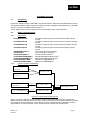
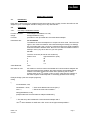
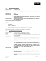
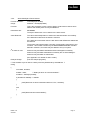
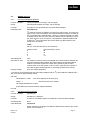
CALIBRE
PICA93LV
Parallel I2C Communications Adapter User Manual
Issue 1.3
22/07/1999
Calibre UK Limited
Cornwall House, Cornwall Terrace
Bradford, West Yorkshire, BD87JS, England
Tel No : (01274) 394125
FAX No: (01274) 730960)
E-mail: [email protected]
Web-site www.calibreuk.com
CALIBRE
Welcome to the Calibre parallel I2C interface. This interface is designed to allow users to run
I2C Bus operations via PC parallel port.
If you have any queries relating to this or any other I2C product supplied by Calibre please visit
our web site www.calibreuk.com.
For technical support please e-mail [email protected] or send your queries by fax to
(44) 1274 730960, for the attention of our I2C Technical Support Department.
COPYRIGHT
This document and the software described within it are copyrighted with all rights reserved. Under
copyright laws, neither the documentation nor the software may be copied, photocopied, reproduced,
translated, or reduced to electronic medium or machine readable form, in whole or in part, without
prior written consent of Calibre UK Ltd ("Calibre"). Failure to comply with this condition may result in
prosecution.
Calibre does not warrant that this software package will function properly in every hardware/software
environment. For example, the software may not work in combination with modified versions of the
operating system or with certain network adapter drivers.
Although Calibre has tested the software and reviewed the documentation, CALIBRE MAKES NO
WARRANTY OR REPRESENTATION, EITHER EXPRESS OR IMPLIED, WITH RESPECT TO THIS
SOFTWARE OR DOCUMENTATION, THEIR QUALITY, PERFORMANCE, MERCHANTABILITY, OR
FITNESS FOR A PARTICULAR PURPOSE. THIS SOFTWARE AND DOCUMENTATION ARE
LICENSED 'AS IS', AND YOU, THE LICENSEE, BY MAKING USE THEREOF, ARE ASSUMING THE
ENTIRE RISK AS TO THEIR QUALITY AND PERFORMANCE.
IN NO EVENT WILL CALIBRE BE LIABLE FOR DIRECT, INDIRECT, SPECIAL, INCIDENTAL, OR
CONSEQUENTIAL DAMAGES ARISING OUT OF THE USE OR INABILITY TO USE THE
SOFTWARE OR DOCUMENTATION, even if advised of the possibility of such damages. In
particular, and without prejudice to the generality of the foregoing, Calibre has no liability for any
programs or data stored or used with Calibre software, including costs of recovering such programs or
data.
Copyright
(c) 1999
Calibre UK Ltd
Cornwall House, Cornwall Terrace
Bradford, BD8 7JS. UK.
E-mail: [email protected]
Web site www.calibreuk.com
All World-wide Rights Reserved
Issue 1.3 22/07/1999
All trade marks acknowledged
Calibre operates a policy of continued product improvement, therefore specifications are subject to
change without notice as products are updated or revised.
E&OE.
Issue 1.3
22/07/1999
CALIBRE
Contents
INTRODUCTION
1.1. General Introduction
1.2. Packing List
1.3. . Configuring the Adapter
1.4. Bus Termination and Protection
1.5. Installing the Adapter
CONNECTING THE ADAPTER TO YOUR SYSTEM
2.1. Connector Pinout
2.2. Bus Capacitance Limitations
2.3. Power Supply
2.4. Resetting the Adapter
SOFTWARE UTILITIES
3.1. Introduction
3.2. DOS C Library/Programs
3.3. DOS QBASIC Library/Programs
3.4. Windows LIB/DLL Functions
USING THE UTILITIES
4.1. Introduction
4.2. C Routines
4.3. QBASIC Routines
4.4. Libraries for Programming in Microsoft Windows Environments
FURTHER INFORMATION
APPENDIX A Parallel I2C Communications Adapter Status Codes
APPENDIX B Parallel I2C Communications Adapter Control Codes
THE MOST COMMONLY ASKED I2C QUESTIONS
6.1. General Questions
6.2. DOS Software Questions
6.3. WINDOWS 95 and NT Questions
Issue 1.3
22/07/99
1
1
1
1
1
2
3
3
3
3
3
4
4
4
5
6
7
7
7
14
20
27
28
29
30
30
30
30
Page i
CALIBRE
INTRODUCTION
1.1.
General Introduction
The Parallel I2C Communications Adapter is designed to connect to any IBM PC compatible parallel
port. It is based on the Philips PCF8584 bus controller, it features full I2C bi-directional compatibility as
either a master or slave. I2C connections are made via a 9 way "D" socket.
1.2.
Packing List
Your Parallel I2C Communications Adapter is supplied with the following items:A.
I2C CD - ROM
B.
The PICA93LV unit (the actual adapter)
C.
A cable set
1
25 way parallel cable
2
6 pin mini DIN male -> 6 pin mini DIN male
3
5 pin DIN female -> 6 pin mini DIN male
4
6 pin mini DIN female -> 5 pin DIN male
1.3..
Configuring the Adapter
NOTE:
MANY COMPONENTS ON THE ADAPTER CARD ARE STATIC SENSITIVE. OBSERVE
NORMAL STATIC SENSITIVE PRECAUTIONS WHEN HANDLING THE CARD!
The adapter is supplied in a standard configuration which should suit most applications. However, the
bus termination and protection are link selectable. Read the following section to change the
configuration.
The standard configuration is bus termination and protection off
1.4.
Bus Termination and Protection
Normally the system to which the Parallel I2C Communications Adapter is to be connected should
already have master pull up resistors fitted to the SCL and SDA lines. If this is not the case, LK6 and
LK7 can be used to connect 4.7K pull up resistors to the 5V supply on these lines.
The standard configuration is with these resistors disconnected.
The SCL and SDA lines are protected by 100R series resistors before exiting the adapter via the 9
way "D" socket. Upstream of the series resistors, the SCL and SDA pins on the PCF8584 are pulled
up with high value resistors (10K). These ensure that the I2C Bus is in a defined state even if no other
devices are connected.
LK4 and LK5 connect optional protection diodes to the SCL and SDA lines. When selected, these
lines are clamped to the 0V and + 5V lines giving protection against transients. If these diodes are
connected, the external I2C system will not function if the adapter is connected but not powered up.
The standard configuration is with these diodes disconnected.
Issue 1.3
22/07/99
Page 1
CALIBRE
1.5.
Installing the Adapter
Connect the PICA93LV to your PC as shown in figure 1 ( the cable numbers correspond to the
packing list above).
Figure 1.0 TYPICAL PC CONNECTION
Issue 1.3
22/07/99
Page 2
CALIBRE
CONNECTING THE ADAPTER TO YOUR SYSTEM
2.1.
Connector Pinout
All external connections are made via a 9 way "D" socket:
2.2.
Pin
Normal Mode
1
0V
2
0V
3
0V
4
0V
5
NC
6
SDA (Bi-directional)
7
+5V
8
SCL (Bi-directional)
9
NC
Bus Capacitance Limitations
The maximum allowable capacitance on the I2C bus in normal mode depends on the value of the SCL
and SDA master pull-ups, but never exceeds 400pF. Refer to Phillips Technical Handbook Book 4
Parts 12a and 12b for further details (see Further Information for references). Care should be taken in
choosing a length and type of interconnecting cable which will not exceed this limit.
2.3.
Power Supply
Pin 7 on the "D" connector is connected to the PICA93LV power supply. This supply is fitted with
overload protection and up to 0.250mA can be drawn from here.
When shipped to you the bus voltage was factory pre-set to 3.3V for use with low voltage memories.
You can adjust the voltage by inserting a small screwdriver through the hole in the front panel.
Your PICA93LV has been factory set for use on 3.3V I2C bus systems. Use on 5V I2C bus
systems without adjusting the voltage WILL CAUSE PERMANENT DAMAGE to the PICA93LV.
The fault is factory detectable and you WILL BE CHARGED FOR THE REPAIR.
2.4.
Resetting the Adapter
Each time the PICA93LV is re-configured via the Setup function it is automatically reset by software.
Issue 1.3
22/07/99
Page 3
CALIBRE
SOFTWARE UTILITIES
3.1.
Introduction
Unpack the software from the CD-ROM in accordance with the instructions provided with the licence.
The Software utilities contain simple DOS routines in both C, QBASIC and Windows DLL / LIB (16bit
only) for use with Visual Basic and Microsoft C++.
These utilities can be used for setup the PICA and to perform basic communications.
3.2.
DOS C Library/Programs
3.2.1.
Files on disc
\C\CLIB\SPICA.LIB
\C\CLIB\CPICA.LIB
\C\CLIB\MPICA.LIB
\C\CLIB\LPICA.LIB
\C\LIBSOURC\PICA.C
\C\INC\PICA.H
\C\SOURCE\I2CINC.C
\C\SOURCE\PROMREAD.C
\C\SOURCE\PROMWRIT.C
\C\SOURCE\READ.MAK
\C\SOURCE\WRITE.MAK
3.2.2.
The library containing the low level functions (small memory
model)
The library containing the low level functions (compact memory
model)
The library containing the low level functions (medium memory
model)
The library containing the low level functions (large memory
model)
The source code for the libraries
The include file for the library
The I2C transfer functions
Sample EEPROM reading function
Sample EEPROM writing function
Make file for PROMREAD.C
Make file for PROMWRIT.C
Typical C Project Arrangement
#include DOS.H
PICA.H
MAKELIB
XPICA.LIB
PICA.C
#include PICA.H Compile
I2CINC.OBJ
I2CINC.C
LINK
PROMREAD.EXE
User applicationCompile PROMREAD.OBJ
e.g. PROMREAD.C
Figure 2.0 Typical Project Arrangement.
Figure 2.0 shows a typical C project, Calibre UK Ltd have produced the library files, SPICA.LIB,
MPICA.LIB, CPICA.LIB and LPICA.LIB, which contains all the low level functions required to interface
to the adapter via the parallel port. These libraries cover the standard memory models, the library
appropriate to the memory model of your project will require linking with the object files.
Issue 1.3
22/07/99
Page 4
CALIBRE
The I2CINC.C file contains all the functions required to build an I2C transfer. This will require
compiling (note the include file) to produce an object file. Once the object files have been created link
them together with the library file to create your applications executable file.
The functions contained in I2CINC.C are as detailed below:Subroutine Name
setup
getstatus
sendaddress
sendstop
writebyte
readbyte
restart
Brief Functional Description
Sets user defined initial conditions.
Reads status register.
Sends slave address, data transmission mode and start signal.
Sends stop signal.
Writes a byte of data to a previously specified address.
Reads a byte of data from a previously specified address.
Sends Restart and slave address of device which is to be communicated
with, without sending a Stop.
Two sample programs are also supplied, these examples show how the functions provided in
I2CINC.C are put together to provide a complete I2C transfer. The sample programs are:PROMREAD.C
PROMWRIT.C
Reads a number of bytes from an I2C serial EEPROM.
Writes a number of bytes to an I2C serial EEPROM.
These programs were compiled using the Zortech C compiler the make files used are supplied. If you
are using the Zortech C compiler copy the desired make file to MAKEFILE then type MAKE<CR>.
Editing the make files will reveal that the file I2CINC.C is compiled and linked with the application.
The makefiles are:READ.MAK
WRITE.MAK
The make file for PROMREAD.C
The make file for PROMWRIT.C
If you are not using the Zortech C compiler you will have to create a similar make file - see your
compiler documentation for further information.
3.3.
DOS QBASIC Library/Programs
3.3.1.
Files on disc
\B\SOURCE\I2CINC.BAS
\B\SOURCE\PROMREAD.BAS
\B\SOURCE\PROMWRIT.BAS
The I2C transfer functions
Sample EEPROM reading function
Sample EEPROM writing function
The I2C functions contained in I2CINC.BAS are detailed below:Subroutine Name
setup
getstatus%
sendaddress%
sendstop%
writebyte%
readbyte%
restart%
Brief Functional Description
Sets user defined initial conditions.
Reads status register.
Sends slave address, data transmission mode and start signal.
Sends stop signal.
Writes a byte of data to a previously specified address.
Reads a byte of data from a previously specified address.
Sends restart and slave address of device which is to be communicated with,
without sending a Stop.
Two sample programs are also supplied, these examples show how the functions provided in
I2CINC.BAS are put together to provide a complete I2C transfer. The sample programs are:PROMREAD.BAS
Reads a number of bytes from an I2C serial EEPROM.
PROMWRIT.BAS
Writes a number of bytes to an I2C serial EEPROM.
Issue 1.3
22/07/99
Page 5
CALIBRE
3.4.
Windows LIB/DLL Functions
3.4.1.
Files on disc
\readme.doc
\win\c\I2cinc.h
\win\c\lpti2c.lib
User Information
"C" function prototypes
I2C "C" library
\win\vb30\lpti2c.bas
\win\vb30\lpti2c.dll
Visual Basic 3.0 declarations
I2C Visual Basic dynamic link library
The following functions are implemented in the windows libraries:void far _pascal _export setup (int baseaddress, int ownaddress, int sclk, int statuswait);
int far _pascal _export sendaddress (int slaveaddress, int setnack);
int far _pascal _export restart (int slaveaddress, int setnack);
int far _pascal _export getstatus (void);
int far _pascal _export writebyte (int wrData);
int far _pascal _export readbyte (int setnack);
int far _pascal _export sendstop (void);
int far _pascal _export recover (void);
int far _pascal _export sendbytes (int __far *transferarray);
int far _pascal _export getbytes (int __far *transferarray);
void far _pascal _export slavelastbyte (void);
Issue 1.3
22/07/99
Page 6
CALIBRE
USING THE UTILITIES
4.1.
Introduction
Each utility is documented in a standard format which lists its name, usage, function and effect on the
adapter is given. The adapter should be setup prior to any data transfer.
4.2.
C Routines
4.2.1.
I2C Setup / Initialisation Routine
Function definition:
void setup(int ownaddress, int sclk)
Usage:
setup(ownaddress, sclk);
Function:
procedure to set up Parallel I2C Communications Adapter.
Parameters are:
int ownaddress
The address to which the adapter is to respond in slave mode. This forms the
upper 7 bits of the 8 bit address, the lowest bit being the Read(1) or Write(0)
bit. This means that if own = 0x57, the card will respond to a Write to address
0xAE and a Read to address 0xAF. Be sure not to select an address which is
already in use by any other device in your I2C system.
int sclk
The SCL clock rate (bit rate for I2C serial bus).
Value of sclk
0
1
2
3
Approximate SCL (KHz)
90
45
11
1.5
Value Returned:
none.
I2C status on exit:
I2C status on exit from routine the Parallel I2C Communications Adapter will
have the serial interface enabled, also data reception acknowledge will be
enabled. The status register will contain 0x81 (assuming that no other
masters exist on the I2C system, if this is not the case then the contents of
the status register will also depend on externally generated bus activity).
Example Usage: (see also sample programs)
main()
{
int ownaddress, sclk;
ownaddress = 0x57;
/* Own slave address set to 0x57 (hex) */
sclk = 1;
/* Serial clock rate set to 45KHz */
setup(ownaddress, sclk);
printf("Parallel I2C Communications Adapter initialised\n");
}
/* This will set up the Parallel I2C Communications Adapter with */
/*an I2C slave address of 0xAE and a SCL clock rate of approximately 45KHz */
Issue 1.3
22/07/99
Page 7
CALIBRE
4.2.2.
I2C Status Checking Routine
Function definition:
int getstatus(void)
Usage:
i2cstatus = getstatus();
Function:
function to read status register of the Parallel I2C Communications Adapter.
Parameters are:
None
Value Returned:
int i2cstatus
where i2cstatus is an integer from 0x00 to 0xFF which indicates the current
status of Parallel I2C Communications Adapter. See Appendix A for details of
the status values returned.
I2C status on exit:
the status of the Parallel I2C Communications Adapter will not be affected by
using the getstatus function.
Example Usage: (see also sample programs)
main()
{
int i2cstatus;
i2ctatus = getstatus ();
printf("Parallel I2C Communications Adapter Status = %x\n", i2cstatus);
}
/*This will read the Parallel I2C Communications Adapter's current status*/
4.2.3.
I2C Address and Start Sending Routine
Function definition:
int sendaddress (int slaveaddress, int setnack)
Usage:
i2cstatus = sendaddress(slaveaddress, setnack)
Function:
This is the procedure to send Start and slave address of device which is to be
communicated with.
Parameters are:
int slaveaddress
The 8 bit slave address of the device which is to be communicated with. This
will be an even number if the adapter is to write to the slave, add 1 to get an
odd number if the adapter is to read from the slave.
int setnack
This controls whether the Parallel I2C Communications Adapter transmits an
Acknowledge down the I2C Bus on reception of a byte. The last byte received
during a transfer must not be acknowledged. If setnack = 0 then acknowledge
is enabled, if setnack = 1 then acknowledge is disabled. Therefore, if a read
(odd numbered) address is being sent AND only 1 byte is to be read, setnack
should be set = 1; in all other cases it must be clear = 0.
Value Returned:
int i2cstatus
The value returned depends on whether the Start and address were sent.
If the start and address have been sent then the status returned will either be
0x00 (bus busy data sent and acknowledged), or 0x08 (bus busy, data sent
but not acknowledged).
If the start or the address cannot be sent (either the bus remained busy or the
address did not get sent) then the last status read IORed with 0x8000 will be
returned.
Issue 1.3
22/07/99
Page 8
CALIBRE
The function will read the status a number of times before returning an error
condition - this number is defined by the MAXNUMBEROFGOES constant
defined in I2CINC.C, this value may be altered to suit your system.
I2C status on exit
0x00 bus busy and address sent and acknowledged
0x08 bus busy and address sent but not acknowledged
0x80 bus busy and address not sent.
(see Appendix A for details of Status codes).
Example Usage:
(see also sample programs)
/* This will send a start and the I2C Slave Address of the device to be communicated with. */
main()
{
int slaveaddress, setnack, i2cstatus;
slaveaddress = 0xa0;
/* I2C Address of slave, this is a typical */
/* write for an I2C static RAM or EEPROM */
setnack = 0;
/* Enable Acknowledge (see parameter descriptions) */
i2cstatus = sendaddress(slaveaddress, setnack);
switch i2cstatus
{
case 0x00:
printf("Start and I2C Slave Address sent and acknowledged\n");
case 0x08:
printf("Start and I2C Slave Address sent and not acknowledged\n");
default:
printf("Start not sent status is %x", i2cstatus);
}
}
4.2.4.
I2C Read Data Byte from Slave Routine
Function definition:
int readbyte(int setnack)
Usage:
i2cdata = readbyte(setnack);
Function:
This is the function to read a byte of data from a slave device whose slave
read address has already been sent by sendaddress (or restart). It can be
used to disable acknowledge after reading data if it is the last but one byte to
be read.
Note: First byte read after read-address is always that address and should be
discarded. This byte should be ignored when working out when to
acknowledge/not acknowledge.
Issue 1.3
22/07/99
Page 9
CALIBRE
Parameters are:
int setnack
This controls whether the Parallel I2C Communications Adapter transmits an
Acknowledge down the I2C Bus on reception of a byte. The last byte received
during a transfer must not be acknowledged. If setnack = 0 then acknowledge
is enabled, if setnack = 1 then acknowledge is disabled. Therefore, if the
LAST BUT ONE byte is to be read, setnack should be set to = 1; in all other
cases it must be clear = 0. (in case of reading 1 byte only, acknowledge will
have been disabled be sendaddress (or restart) and so should know be
enabled again after reading the data.
Value Returned:
int i2cdata
The value returned depends on whether the data was read successfully.
If the data was read then the value is returned.
If the data cannot be read (because there is none in the register) then the last
status read IORed with 0x8000 will be returned.
The function will read the status a number of times before returning an error
condition - this number is defined by the MAXNUMBEROFGOES constant
defined in I2CINC.C, this value may be altered to suit your system.
I2C status on exit :
0x00 bus busy and unread data in data register.
0x80 bus busy and no unread data in data register
The value will depend on whether any more bytes of data have been
transmitted by the slave device which is being read.
(See Appendix A for details status codes).
Example Usage:
(see also sample programs)
/* This will read a byte of data from a slave previously addressed */
/* by and with acknowledge already disabled by sendaddress. */
/* After reading the data, acknowledge will be re-enabled. */
main()
{
int setnack, i2cdata;
setnack = 0;
/* Enable acknowledge - only one byte it to */
/* be read (see parameter descriptions) */
i2cdata = readbyte(setnack);
if (i2cdata & 0x8000) == 0x8000
{
printf("Data read fault i2c status %x", i2cdata);
}
else
{
printf("Data read was %x\n", i2cdata);
}
}
Issue 1.3
22/07/99
Page 10
CALIBRE
4.2.5.
Write Data Byte to Slave Routine
Function definition:
int writebyte(int i2cdata)
Usage:
i2cstatus = writebyte(i2cdata)
Function:
This is the procedure to write a byte of data to a slave device whose slave
address has already been sent by sendaddress.
Parameters are:
int i2cdata
The byte of data which is to be written to the slave device.
Value Returned:
The value returned depends on whether the data was written successfully.
If the data was written then the status is returned.
If the data cannot be written then the last status read IORed with 0x8000 will
be returned.
The function will read the status a number of times before returning an error
condition - this number is defined by the MAXNUMBEROFGOES constant
defined in I2CINC.C, this value may be altered to suit your system.
I2C status on exit:
0x00 bus busy and data transmitted and acknowledged successfully.
0x08 bus busy and data transmitted successfully but not acknowledged .
0x80 bus busy and data not transmitted
(See Appendix A for details of status codes).
Example Usage:
(see also sample programs)
/* This will write a byte of data to a slave previously addressed by sendaddress. */
main()
{
int i2cdata, i2cstatus;
i2cdata = 0x69;
/* Data byte which is to be transmitted */
i2cstatus = writebyte (i2cdata) ;
if (i2cstatus & 0x8000) == 0x8000
{
printf("Data has not been transmitted status is %x\n", i2cstatus);
}
else
{
printf("Data has been transmitted\n");
}
}
Issue 1.3
22/07/99
Page 11
CALIBRE
4.2.6.
Send an I2C Stop Routine
Function definition:
int sendstop(void)
Usage:
i2cstatus = sendstop();
Function:
This is the procedure to send a stop (end of communication signal) down the
I2C Bus, ending a transmission or reception with a slave which was
addressed previously by sendaddress.
Parameters are:
None.
Value Returned:
int i2cstatus.
The value returned depends on whether the bus became free.
If the bus became free then the status (0x81) is returned.
If the bus does not became free then the last status read IORed with 0x8000
will be returned.
The function will read the status a number of times, waiting for the bus to
become free, before returning an none free status - this number is defined by
the MAXNUMBEROFGOES constant defined in I2CINC.C, this value may be
altered to suit your system.
I2C status on exit:
The status of the Parallel I2C Communications Adapter will be 0x81 - bus idle
and no unread / untransmitted data in data register.
Note - this may not be the case in a system where there is another master as
well as the Parallel I2C Communications Adapter, since this other master
may well have taken control of the bus by the time a program next uses
getstatus to read the status register.
(See Appendix A for details of status codes).
Example Usage:
(see also sample programs)
/* This will write a Stop to the I2C Bus */
main()
{
int i2cstatus;
i2cstatus = sendstop();
printf("Stop has been transmitted status is %x\n", i2cstatus);
}
4.2.7.
I2C Restart and Address Sending Routine
Function Definition:
int restart(int slaveaddress, int setnack)
Usage:
i2cstatus = restart(slaveaddress, setnack)
Function:
This is the procedure to send Restart and slave address of device which is to
be communicated with, without a Stop having been sent at the end of last
transmission/reception. This routine is particularly useful for reading
memories which must first have a data pointer written to them to select where
the read is to occur from, and must have their address sent a Restart to
proceed with the read operation.
Issue 1.3
22/07/99
Page 12
CALIBRE
Parameters are:
int slaveaddress
The slave address of the device which is to be communicated with. This will
be an even number if the adapter is to write to the slave, add 1 to get an odd
number if the adapter is to read from the slave.
int setnack
This controls whether the Parallel I2C Communications Adapter transmits an
Acknowledge down the I2C Bus on reception of a byte. The last byte received
during a transfer must not be acknowledged, in all other cases acknowledge
must be enabled, If setnack = 0 then acknowledge is enabled, if setnack = 1
then acknowledge is disabled. Therefore, if a read (odd numbered) address is
being sent AND only 1 byte is to be read, setnack should be set to = 1; in all
other cases it must be clear = 0.
Value Returned:
int i2cstatus
The value returned depends on whether the Start and address were sent.
If the start and address have been sent then the status returned will either be
0x00 (bus busy data sent and acknowledged), or 0x08 (bus busy, data sent
but not acknowledged).
If the start or the address cannot be sent (either the bus remained busy or the
address did not get sent) then the last status read IORed with 0x8000 will be
returned.
The function will read the status a number of times before returning an error
condition - this number is defined by the MAXNUMBEROFGOES constant
defined in I2CINC.C, this value may be altered to suit your system.
I2C status on exit
0x00 bus busy and address sent and acknowledged
0x08 bus busy and address sent but not acknowledged
0x80 bus busy and address not sent.
(see Appendix A for details of status codes).
Example Usage:
(see also sample programs)
main()
{
int slaveaddress, setnack, trash;
slaveaddress = 0xa1;
/* I2C Address of slave, this is a typical read */
/* address for an I2C static RAM or EEPROM */
setnack = 0;
/* Enable Acknowledge (see parameter descriptions)*/
i2cstatus = restart(slaveaddress, setnack);
trash = readbyte(setnack);
/* read the address from the adapter and discard*/
}
Issue 1.3
22/07/99
Page 13
CALIBRE
4.3.
QBASIC Routines
4.3.1.
I2C Setup/Initialisation Routines
Function definition:
setup (ownaddress as integer, sclk as integer)
Usage
call setup(ownaddress as integer, sclk as integer)
Function:
procedure to set up Parallel I2C Communications Adapter.
Parameters are:
ownaddress%
I2C address to which the adapter is to respond in slave mode. This forms the
upper 7 bits of the 8 bit address, the lowest bit being the Read(1) or Write (0)
bit. This means that if ownaddress% = &h57, the card will respond to a Write
to address &hAF. Be sure not to select an address which is already in use by
any other device in your I2C system. If ownaddress% &h00 the adapter will
monitor all I2C bus information but will not affect any data transfers, thus
acting as a bus monitor.
sclk%
the SCL clock rate (bit rate for I2C serial bus).
Value of sclk%
0
1
2
3
Approximate SCL (KHz)
90
45
11
1.5
Value Returned:
none.
I2C status on exit:
I2C status on exit from routine the Parallel I2C Communications Adapter will
have the serial interface enabled, also data reception acknowledge will be
enabled. The status register will contain 0x81 (assuming that no other
masters exist on the I2C system, if this is not the case then the contents of
the status register will also depend on externally generated bus activity).
Example Usage:
(see also sample programs)
' This will set up the Parallel I2C Communications Adapter with an I2C slave address of &HAE and a
SCL clock rate of approximately 45KHz
sub main
ownaddress% = &h57
' Own slave address set to &h57 (hex)
sclk% = 1
' Serial clock rate set to 45KHz
call setup(ownaddress%, sclk%)
print"Parallel I2C Communications Adapter initialised"
end sub
4.3.2.
I2C Status Checking Routine
Function definition:
getstatus%()
Usage:
I2Cstatus% = getstatus
Function:
function to read status register of Parallel I2C Communications Adapter.
Parameters are:
None.
Value Returned:
i2cstatus%
where i2cstatus is an integer from &H00 to &HFF which indicates the current
status of the PICA93LV.
Issue 1.3
22/07/99
Page 14
CALIBRE
See Appendix A for details of the status values returned.
I2C status on exit:
The status of the Parallel I2C Communications Adapter will not be affected by
using the FNgetstatus% function.
Example Usage:
(see also sample programs)
'This will read the Parallel I2C Communications Adapters current status
sub main
i2cstatus% = getstatus
print"Parallel I2C Communications Adapter Status = " + hex$(i2cstatus)
end sub
4.3.3.
I2C Address and Start Sending Routine
Function definition:
sendaddress(slaveaddress as integer, setnack as integer)
Usage:
i2cstatus = sendaddress(slaveaddress%, setnack%)
Function:
procedure to send Start and slave address of device which is to be
communicated with.
Parameters are:
slaveaddress%
The slave address of the device which is to be communicated with. This will
be an even number if the adapter is to write to the slave, add 1 to get an odd
number if the adapter is to read from the slave.
setnack%
This controls whether the Parallel I2C Communications Adapter transmits an
Acknowledge down the I2C Bus on reception of a byte. The last byte received
during a transfer must not be acknowledged, in all other cases acknowledge
must be enabled. If setnack% = 0 then acknowledge is enabled, if setnack%
= 1 then acknowledge is disabled. Therefore, if a read (odd numbered)
address is being sent AND only 1 byte is to be read, setnack% should be set
to = 1; in all other cases it must be clear = 0.
Value Returned:
I2cstatus%
The value returned depends on whether the Start and address were sent.
If the start and address have been sent then the status returned will either be
&H00 (bus busy data sent and acknowledged), or 0x08 (bus busy, data sent
but not acknowledged).
If the start or the address cannot be sent (either the bus remained busy or the
address did not get sent) then the last status read IORed with &H8000 will be
returned.
The function will read the status a number of times before returning an error
condition - this number is defined by the MAXNUMBEROFGOES constant
defined in I2CINC.BAS, this value may be altered to suit your system.
I2C status on exit
&H00 bus busy and address sent and acknowledged
&H08 bus busy and address sent but not acknowledged
&H80 bus busy and address not sent.
(see Appendix A for details of Status codes).
Example Usage:
(see also sample programs)
' This will send a Start and the I2C Slave Address of the device to be communicated with.
Issue 1.3
22/07/99
Page 15
CALIBRE
Sub Main
slaveaddress% = &HA0
' IC Address of slave, this is a typical write
' address for an I2C static RAM or EEPROM
setnack% = 0
' Enable Acknowledge (see parameter descriptions)
i2cstatus% = sendaddress (slaveaddress%, setnack%)
Select Case i2cstatus%
case &H00
print "Start and I2C Slave Address sent and acknowledged"
case &H08
print "Start and I2C Slave Address sent and not acknowledged"
case else
print "Start not sent status is " + Hex$( i2cstatus%)
End Select
End sub
4.3.4.
I2C Read Data Byte from Slave Routine
Function definition:
readbyte%(setnack as integer)
Usage:
i2cdata% = readbyte%(setnack%)
Function:
function to read a byte of data from a slave device whose slave address has
already been sent by sendaddress. Can be used to disable acknowledge after
reading data if it is the last but one byte to be read.
Parameters are:
setnack%
This controls whether the Parallel I2C Communications Adapter transmits
and Acknowledge down the I2C Bus on reception of a byte. The last byte
received during a transfer must not be acknowledged, in all other cases
acknowledge must be enabled. If setnack% = 0 then acknowledge is enabled,
if setnack% = 1 then acknowledge is disabled. Therefore, if the LAST BUT
ONE byte is to be read, setnack% should be set to =1; in all other cases it
must be clear = 0. (In the case of reading 1 byte only, acknowledge will have
been disabled by sendaddress and so should now be enabled again after
reading the data.)
Value Returned:
i2cdata%
The value returned depends on whether the data was read successfully.
If the data was read then the value is returned.
If the data cannot be read (because there is none in the register) then the last
status read IORed with &H8000 will be returned.
The function will read the status a number of times before returning an error
condition - this number is defined by the MAXNUMBEROFGOES constant
defined in I2CINC.C, this value may be altered to suit your system.
I2C status on exit :
0x00 bus busy and unread data in data register.
0x80 bus busy and no unread data in data register
The value will depend on whether any more bytes of data have been
transmitted by the slave device which is being read.
Issue 1.3
22/07/99
Page 16
CALIBRE
(See Appendix A for details status codes).
Example Usage:
(see also sample programs)
' This will read a byte of data from a slave previously addressed by and with acknowledge already '
disabled by sendaddress. After reading the data, acknowledge will be re-enabled.
Sub Main
setnack% = 0
' Enable Acknowledge - only one byte is to be read
' (see parameter descriptions)
i2cdata% = readbyte(setnack%)
if i2cdata and &H8000 = &H8000 then
print "Data read fault i2c status " + Hex$(i2cdata%)
else
print "Data read was " + Hex$(i2cdata%)
end if
Exit Sub
4.3.5.
Write Data Byte to Slave Routine
Function definition:
writebyte%(i2cdata as integer)
Usage:
i2cstatus% = writebyte(i2cdata%)
Function:
procedure to write a byte of data to a slave device whose slave address has
already been sent by sendaddress.
Parameters are:
i2cdata%
The byte of data which is to be written to the slave device.
Value Returned:
The value returned depends on whether the data was written successfully.
If the data was written then the status is returned.
If the data cannot be written then the last status read IORed with &H8000 will
be returned.
The function will read the status a number of times before returning an error
condition - this number is defined by the MAXNUMBEROFGOES constant
defined in I2CINC.BAS, this value may be altered to suit your system.
I2C status on exit:
&H00 bus busy and data transmitted and acknowledged successfully.
&H08 bus busy and data transmitted successfully but not acknowledged .
&H80 bus busy and data not transmitted
(See Appendix A for details of Status codes).
Issue 1.3
22/07/99
Page 17
CALIBRE
Example Usage:
(see also sample programs)
' This will write a byte of data to a slave previously addressed by sendaddress. */
Sub main
i2cdata$ = &H69
' Data byte which is to be transmitted */
i2cstatus$ = writebyte (i2cdata$)
if (i2cstatus and &H8000) = &H8000 then
print "Data has not been transmitted status is " + HEX$( i2cstatus%)
else
print "Data has been transmitted"
End If
End Sub
4.3.6.
Send an I2C Stop Routine
Function definition:
sendstop%()
Usage:
i2cstatus% = sendstop
Function:
procedure to send a Stop (end of communication signal) down the I2C Bus,
sending a transmission or reception with a slave which was address
previously by sendaddress.
Parameters are:
None.
Value Returned:
i2cstatus%.
The value returned depends on whether the bus became free.
If the bus became free then the status (&H81) is returned.
If the bus does not became free then the last status read IORed with &H8000
will be returned.
The function will read the status a number of times, waiting for the bus to
become free, before returning an none free status - this number is defined by
the MAXNUMBEROFGOES constant defined in I2CINC.BAS, this value may
be altered to suit your system.
I2C status on exit:
The status of the Parallel I2C Communications Adapter will be &H81 - bus
idle and no unread / untransmitted data in data register.
Note - this may not be the case in a system where there is another master as
well as the Parallel I2C Communications Adapter, since this other master
may well have taken control of the bus by the time a program next uses
getstatus to read the status register.
(See Appendix A for details of status codes).
Example Usage:
(see also sample programs)
' This will write a Stop to the I2C Bus
sub main
i2cstatus = sendstop
print "Stop has been transmitted status is " + HEX$( i2cstatus%)
end sub
Issue 1.3
22/07/99
Page 18
CALIBRE
4.3.7.
I2C Restart and Address Sending Routine
Function definition:
restart%(slaveaddress as integer setnack as integer)
Usage:
i2cstatus% = restart(slaveaddress%, setnack%)
Function:
procedure to send Restart and slave address of device which is to be
communicated with, without a Stop having been sent at the end of the last
transmission/reception. This routine is particularly useful for reading
memories which must first have a data pointer written to them to select where
the read is to occur from, and must then have their read address sent with a
Restart to proceed with the read operation.
Parameters are:
slaveaddress%
The slave address of the device which is to be communicated with. This will
be an even number if the communicated with. This will be an even number if
the adapter is to write to the slave, add 1 to get an odd number if the adapter
is to read from the slave.
setnack%
This controls whether the Parallel I2C Communications Adapter transmits an
Acknowledge down the I2C Bus on reception of a byte. The last byte received
during a transfer must not be acknowledged, in all other cases acknowledge
must be enabled. If setnack% = 0 then acknowledge is enabled, if setnack%
= 1 then acknowledge is disabled. Therefore, if a read (odd numbered)
address is being sent AND only 1 Byte is to be read, setnack% should be set
to = 1; in all other cases it must be clear = 0.
Value Returned:
i2cstatus%
The value returned depends on whether the Start and address were sent.
If the start and address have been sent then the status returned will either be
&H00 (bus busy data sent and acknowledged), or &H08 (bus busy, data sent
but not acknowledged).
If the start or the address cannot be sent (either the bus remained busy or the
address did not get sent) then the last status read IORed with &H8000 will be
returned.
The function will read the status a number of times before returning an error
condition - this number is defined by the MAXNUMBEROFGOES constant
defined in I2CINC.BAS, this value may be altered to suit your system.
I2C status on exit
&H00 bus busy and address sent and acknowledged
&H08 bus busy and address sent but not acknowledged
&H80 bus busy and address not sent.
(see Appendix A for details of Status codes).
Example Usage:
(see also sample programs)
Sub main
slaveaddress% = &HA1
' I2C Address, this is a typical slave read address
setnack% = 0
' Enable Acknowledge (see parameter descriptions)
i2cstatus% = restart(slaveaddress%, setnack%)
trash% = readbyte(setnack%) ' read the address from the adapter and discard
End Sub
Issue 1.3
22/07/99
Page 19
CALIBRE
4.4.
Libraries for Programming in Microsoft Windows Environments
The library function descriptions in this section apply equally to both C++ and Visual Basic
applications.
4.4.1.
Users of ICA90 / 93 I2C adapters
For those customers who have already used the ICA90 or ICA93 I2C adapters and are wishing to
convert there windows applications to the Parallel I2C Adapter the following changes will have to be
made:C++ applications
Change the link option to c:\your path\LPTI2C.LIB.
The I2CINC.H file is identical for both the ICA90 / 93 and the PICA93LV applications.
VB3.0 applications
Replace the project file CALI2C.BAS for the LPTI2C.BAS supplied.
To simplify the conversion the setup function retains the base address parameter, this is not used by
the PICA93LV function and any integer value may be passed (even your existing 310 hex).
4.4.2.
C functions - Function Prototypes
To ensure the prototypes are added correctly copy the file I2CINC.H into the directory containing your
project and add the line:
#include "I2CINC.H"
Remember to add the library LPTI2C.LIB to your project make file.
4.4.3.
Visual Basic 3.0 functions
Add the file LPTI2C.BAS to your project, this contains the declarations for the procedures within the
DLL. If the DLL is not in the root directory change the path to the DLL to suit your system.
The sendbytes and getbytes functions pass the transfer array to the DLL by reference, the following
example indicates how to do this:
ReDim transferarray(0 to 258)
'remember 3 locations are required for
'the slave write and word addresses so
'array allows 256 bytes of data.
transferarray(0) = &HA0
'slave write address.
transferarray(1) = &H00
'slave word address.
transferarray(2) = 256
'the number of bytes.
bytes_sent = sendbytes(transferarray(0))
4.4.4.
setup
Function specification
Void setup(int baseaddress, int ownaddress, int sclk, int statuswait)
Parameters are:
int baseaddress
This has no function and any value may be passed to setup, The
baseaddress has been retained to enable applications written for the ICA90 /
ICA93 to be rapidly ported to the PICA93LV.
int ownaddress
This is the I2C address to which the adapter is to respond in slave mode. This
forms the upper 7 bits of the 8 bit address, the lowest bit being the read(1) or
write(0) bit. This means that if ownaddress = 57H the card will respond to a
write address of AEH and a read address of AFH.
int statuswait
Issue 1.3
22/07/99
Page 20
CALIBRE
This is a period of time (in micro seconds) to wait for the required bus status.
If this time-out expires the I2C functions will exit returning an error code.
int sclk
This is the clock rate (bit rate for the I2C serial bus) when operating as a
master.
Value of sclk
0
1
2
3
Approximate SCL-KHz
90
45
11
1.5
Parameters returned
None.
Prerequisites
None.
Functional description
This function characterises the PC and initialise adapter ready for I2C
transfers.
4.4.5.
sendaddress
Function specification
Int sendaddress(int slaveaddress, int setnack)
Parameters are:
int slaveaddress
This is the address to be accessed via the I2C, e.g. A0H.
int setnack
This controls whether the Parallel I2C Communications Adapter transmits an
Acknowledge down the I2C Bus on reception of a byte. The last byte received
during a transfer must not be acknowledged, in all other cases acknowledge
must be enabled. If setnack = 0 then acknowledge is enabled, if setnack = 1
then acknowledge is disabled. Therefore, if a read (odd numbered) address is
being sent AND only 1 Byte is to be read, setnack should be set to = 1; in all
other cases it must be clear = 0.
Parameters returned
int ErrCode.
If the transfer time out occurs error code 8001H is returned otherwise the
status is returned.
Prerequisites
The adapter must be configured for PC and application by running setup.
Functional description
The function waits for the bus to be free. Then sends the slave address with
the appropriate acknowledge.
The acknowledge is set ready for the data transfer after the address and
hence in read mode (odd address being sent) if only one byte is to be read
the setnack parameter must equal 1. If more than one byte is to be read or if
in write mode (even address being sent) then setnack must equal 0.
The function waits for the address to be sent. Should a time-out occur during
the sending of an address then an error code 8001H is returned, otherwise
the status is returned.
4.4.6.
writebyte
Function specification
Int writebyte(int wrData)
Parameters are:
int wrData
This is the byte of data to be written.
Issue 1.3
22/07/99
Page 21
CALIBRE
Parameters returned
int ErrCode.
If the transfer time out occurs error code 8004H is returned otherwise the
status is returned.
Prerequisites
Adapter must be configured using setup, start and write address sent by
sendaddress.
Functional description
The function writes the data to the adapter and then waits for it to be sent.
Should a time-out occur during the sending of the data then error code 8004H
is returned, otherwise the status is returned.
Writebyte is compatible with both master write and slave write modes.
4.4.7.
readbyte
Function specification
Int readbyte(int setnack)
Parameters are:
int setnack
This controls whether the Parallel I2C Communications Adapter transmits an
Acknowledge down the I2C Bus on reception of a byte. The last byte received
during a transfer must not be acknowledged, in all other cases acknowledge
must be enabled. If setnack = 0 then acknowledge is enabled, if setnack = 1
then acknowledge is disabled. Therefore, if a read (odd numbered) address is
being sent AND only 1 Byte is to be read, setnack should be set to = 1; in all
other cases it must be clear = 0.
Parameters returned
int I2CData
The data read, if a time-out occurs the ErrCode 8005H is returned.
Prerequisites
Adapter must be configured using setup, start and read address sent by
sendaddress.
Functional description
If setnack is 1 the function writes 40H to the control register to establish the
correct acknowledge procedure.
The data is read from the adapter.
Should a time-out occur then an error code 8005H is returned, otherwise the
data is returned.
Readbyte is compatible with both master read and slave read modes.
4.4.8.
sendstop
Function specification
Int sendstop( )
Parameters are:
None.
Parameters returned
int ErrCode.
If the transfer time out occurs error code 8002H is returned otherwise the
status is returned.
Prerequisites
Adapter must be configured using setup. Should normally only be used at the
end of a transmission. Correct acknowledge sequence must have been
applied if the transmission was a read.
Functional description
Instruct the adapter to send a stop code and wait for it to be sent.
Should a time-out occur during the sending of a stop then an error code
8002H is returned, otherwise the status is returned.
Issue 1.3
22/07/99
Page 22
CALIBRE
4.4.9.
restart
Function specification
Int restart(int slaveaddress, int setnack)
Parameters are:
int slaveaddress
The address to be accessed via the I2C, e.g. A1H.
int setnack
This controls whether the Parallel I2C Communications Adapter transmits an
Acknowledge down the I2C Bus on reception of a byte. The last byte received
during a transfer must not be acknowledged, in all other cases acknowledge
must be enabled. If setnack = 0 then acknowledge is enabled, if setnack = 1
then acknowledge is disabled. Therefore, if a read (odd numbered) address is
being sent AND only 1 Byte is to be read, setnack should be set to = 1; in all
other cases it must be clear = 0.
Parameters returned
int ErrCode
If the transfer time out occurs error code 8003H is returned otherwise the
status is returned.
Prerequisites
Adapter must be configured using setup. A start and slave address must
have previously been sent using sendaddress.
Usually a data pointer would already have been written using writebyte.
Functional description
Sends a start code and the slave address specified and presets the
acknowledge status depending on the value of setnack.
The acknowledge is set ready for the data transfer after the address and
hence in read mode (odd address being sent) if only one byte is to be read
the setnack parameter must equal 1. If more than one byte is to be read or if
in write mode (even address being sent) then setnack must equal 0.
The function waits for the address to be sent. Should a time-out occur during
the sending of an address then an error code 8003H is returned, otherwise
the status is returned.
4.4.10.
getstatus
Function specification: Int getstatus(void)
Parameters are:
None.
Parameters returned
int I2Cstatus
The current value of the bus status.
Prerequisites
Adapter must be configured using setup.
Functional description
The function reads status word from the adapter and returns it.
4.4.11.
recover
Function specification
Int recover(void)
Parameters are:
None.
Parameters returned
int ErrCode.
If the bus recovery failed error code 8006H is returned otherwise the status is
returned.
Prerequisites
Issue 1.3
22/07/99
Adapter must be configured using setup.
Page 23
CALIBRE
Functional description
This function issues two consecutive stop commands on the bus, with a delay
in between. It then clears the adapter registers and reads the status. This
should normally set the adapter into a known idle state when a bus error or
other problem has occurred.
If the status does not indicate bus free or the bus Error bit is still set then
8006H is returned otherwise the status is returned.
4.4.12.
sendbytes
Function specification
Int sendbytes(int far *transferarray)
Parameters are:
int far *transferarray
The far pointer must point to a single dimensional array the format of which is
detailed below. The calling function must have initialised elements 0, 1 and 2
prior to calling the function.
Element no
Element name
Description
0
slaveaddress
Slaveaddress is the address to be accessed via the
I2C Bus, this is in hexadecimal e.g. A0H.
1
wordaddress
Wordaddress is the offset within the slave to which
the first byte of data is to be written, see transmission
format for more detail.
2
nobytes
The number of bytes (n) to be sent. Min value 1.
3
byte 0
First byte to be sent.
"
"
byte n
Parameters returned
Last byte to be sent.
int bsent
The number of bytes actually sent.
Prerequisites
Adapter must be configured using setup. Array elements 0, 1 and 2 must be
initialised. Usually elements 3 to n would also be initialised. Array must be
pre-defined to a size at least large enough to hold all the parameters and data
concerned.
Transmission format
There are two transmission formats, these are :
i.
start-slaveaddress-byte(s)-stop
If transmission format i) is required set the wordaddress to a number
greater than FFH.
ii.
start-slaveaddress-wordaddress-byte(s)-stop
If transmission format ii) is required set the wordaddress to a number
less than or equal to FFH.
Functional description
The function determines the required transmission format and then sends a
start code and the slave address.
If transmission format ii) has been selected the wordaddress is sent.
The data bytes are then transmitted sequentially.
Should a time-out occur or the slave not acknowledge a transfer the
transmission is terminated by a stop and the number of bytes actually
transmitted is returned.
Issue 1.3
22/07/99
Page 24
CALIBRE
When all the bytes have been transmitted a stop is issued and the total
number of bytes is returned.
Sendbytes can only be used in master write mode.
4.4.13.
getbytes
Function specification
Int getbytes(int far *transferarray)
Parameters are:
int far *transferarray
The far pointer must point to a single dimensional array the format of which is
detailed below.
The calling function must have initialised elements 0, 1 and 2 prior to calling
the function.
Element no
Element name
Description
0
slaveaddress
Slaveaddress is the address to be accessed via the
I2C Bus, this is in hexadecimal e.g. A0H.
1
wordaddress
Wordaddress is the offset within the slave to which
the first byte of data is to be written, see
transmission format for more detail.
2
nobytes
The number of bytes (n) to be sent. Min value 1.
3
byte 0
First byte read.
"
"
byte n
Parameters returned
Last byte read.
int nobytesread
The number of bytes actually read.
Prerequisites
Adapter must be configured using setup. Array elements 0, 1 and 2 must be
initialised. Elements 3 to n do not need to be initialised since they are where
the read data is returned. The array must be pre-defined to a size at least
large enough to hold all the parameters and data concerned.
Transmission Format
If the slaveaddress has the least significant bit set (1) then this forms a read
address, if the least significant bit is clear (0) then this forms the write
address e.g. A0H is the write address and A1H is the associated read
address.
getbytes supports two transfer formats these being:
i. start-slavereadaddress-byte(s)-stop
To select transfer format i) pass the read address as slaveaddress.
The wordaddress is not used in this format and is ignored by getbytes.
ii. start-slavewriteaddress-wordaddress-restart-slavereadaddress-byte(s)stop
To select transfer format ii) pass the write address as slaveaddress.
In this format the wordaddress must be valid.
wordaddress is pointer to the first byte of data to be read.
nobytestoread is the number of bytes to be read. The minimum value
allowable is 1.
Issue 1.3
22/07/99
Page 25
CALIBRE
Functional description
The function determines the required transfer format, sends the appropriate
sequence of start(s) and slave address(es) and checks for acknowledges
where necessary.
If the slave fails to acknowledge then a stop is sent and nobytesread is
returned equal to 0.
The first data byte read is the slave read address sent (see readbyte
description). This is discarded, it is not returned in the transfer array. The data
bytes are then read and stored in the transfer array. At the appropriate point
acknowledges are ceased - for the last and the last but one byte to be
transferred.
A stop is sent after the last byte has been read. On completion the number of
bytes read is returned.
Should a time-out occur the transfer is terminated by a stop and the number
of bytes successfully read is returned.
Getbytes can only be used in master read mode.
4.4.14.
slavelastbyte
Function specification
void slavelastbyte( )
Parameters returned
none.
Prerequisites
Adapter must be configured using setup. This function would normally only
be called following the end of a transmission in slave write mode - when the
adapter is being read as a slave, by another master, not when writing to a
slave using the adapter.
Functional description
This function is used when the adapter is a slave being read by a master
elsewhere on the bus - the adapter is in slave write mode. The function must
be called immediately after the master indicates the last byte has been read
(by not acknowledging that byte). This function is required to clear the I2C
data lines so that the master can send a stop signal.
Issue 1.3
22/07/99
Page 26
CALIBRE
FURTHER INFORMATION
A) Philips Semiconductors Technical Handbook Book 4 Parts 12a and 12b. These give details of the
I2C compatible ICs, and the I2C Bus specification. The PCF8584P used on the adapter is
included in later editions. Where the data sheet and this manual disagree, this manual should
always be followed when using the adapter.
B) Philips Components Data Sheet for PCF8584
C) Philips Application Note No EIE/AN90001 Interfacing PCF8584 I2C bus controller to 80(C)51
family micro controllers. This gives some useful code but is not written directly for the PC. Please
note - the hardware information on the PCF8584 given in this application note sometimes
contradicts the data sheet referenced in 8.2, in general the data sheet is correct; the only
exception is that a Stop should be sent as C3 (Hex) - as shown in the application, not 43 (hex) implied in the data sheet ) see Appendix B of this manual for details of control codes. Where in
doubt, follow this manual.
Issue 1.3
22/07/99
Page 27
CALIBRE
APPENDIX A Parallel I2C Communications Adapter Status Codes
This is an eight bit register, read using the getstatus routine. The bit definitions are as follows:
Bit 7 (MSB) - The Pending Interrupt Not (PIN) Bit
The PIN bit is a read-only flag which is used to synchronise serial communication. Each time a serial
data transmission is initiated (by sendaddress routine or setting STA bit) the PIN will be set (= 1)
automatically. After successful transmission of one byte (9 clock pulses, including acknowledge), this
bit will be automatically reset (= 0) indicating a complete transmission. When the ENI bit (enable
interrupt) is also set, the PIN triggers an external interrupt via the selected IRQ line when PIN is reset.
When in receiver mode, the PIN is also reset on completion of each received byte. In polled
applications, the PIN bit is tested (using the getstatus routine) to determine when a serial transmission
has been completed. In receiver mode, the PIN bit is tested (using the readbyte function). When the
PIN becomes set all other status bits will be reset, with the exception of the BB (not Bus Busy) bit.
In short, when transmitting data, if PIN = 0 then the data has been sent, if PIN = 1 then it has not.
When receiving data, if PIN = 0 then there is unread received data ready to read, if PIN = 1 then either
the data received has already been read, or no data has yet been received.
Bit 6 - Not Used
This bit is not currently used and will always = 0.
Bit 5 - The STS Bit
When in slave-receiver mode (i.e. transmission initiated by a master elsewhere on the I2C bus), the
flag STS = 1 when an externally generated Stop condition is detected, otherwise STS = 0. This flag is
used only in slave-receiver mode.
Bit 4 - The Bus Error (BER) Bit
BER = 1 when a misplaced Start or Stop has been detected, otherwise BER = 0. This can be quite
serious since the I2C devices on the bus may be left in an undefined state after a bus error has
occurred - in some circumstances the only way to get the bus going again may be to reset all the I2C
devices on it.
Bit 3 - The Last Received Bit /Address 0 "General Call" Address Received (LRB/AD0) Bit
This dual function status bit holds the value of the last received bit over the I2C bus when AAS (Bit 2)
= 0. Normally this will be the value of the slave acknowledge; thus checking for slave
acknowledgement is done via testing of the LRB bit. When AAS (Bit 2) = 1 ("Addressed As Slave"),
the Parallel I2C Communications Adapter has been addressed as a slave and the ADO bit will = 1 if
the slave address received was the "General Call" address. For further information on the "General
Call" Address, see the Philips data books referenced in Further Information Section of this User
Manual.
Bit 2 - The Addressed As Slave (AAS) Bit
When acting as a slave-receiver, this flag is set = 1 when an incoming address over the I2C bus
matches the value defined by the setup routine, or if the slave address received was the I2C bus
"General Call" address (00 Hex). In all other circumstances, AAS = 0.
Bit 1 - The Lost Arbitration Bit (LAB)
This bit is set = 1 when, in multimaster operation (more than one master present on the I2C bus)
arbitration is lost to another master on the I2C bus. In all other circumstances, LAB = 0.
Bit 0 - The Busy Bit (BB)
This is a read-only flag indicating when the I2C bus is in use. BB = 0 indicates that the bus is busy,
and access is not possible (unless of course it is busy because the Parallel I2C Communications
Adapter itself has control of the bus). This bit is set = 1 by Stop conditions and reset = 0 by Start
conditions. In short, BB = 1 means that the bus is free and a new transmission can be started.
Issue 1.3
22/07/99
Page 28
CALIBRE
APPENDIX B Parallel I2C Communications Adapter Control Codes
The Control Register should normally be written using the setup, sendaddress and sendstop routines.
To implement more advanced functions for example, enabling hardware interrupt generation these
routines may need to be modified or the users own routines used in their place.
The Control Register is accessed using the controloutp() and controlinp() functions. The function
definitions for these are as follows:
void controloutp(int controldata);
int controlinp(void);
The Data Register is accessed using the dataoutp() and datainp() functions. The function definitions
for these are as follows:
void dataoutp(int controldata);
int datainp(void);
E.g. in C, controloutp(0xc3); would cause an Parallel I2C Communications Adapter to generate a Stop
condition on the I2C bus. For detailed information on these codes, the Philips data sheet on the
PCF8584 device (see Further Information section).
0x00
read/write own address register (followed by a data byte to the data register).
0x20
read/write clock register (followed by a data byte to the data register).
After either of the above operations, 0x41 must be written to the control register to re-enable the I2C
interface.
0xC3
send a Stop signal over the I2C bus.
0x41
I2C NOP (no operation) instruction, acknowledge enabled. (Use 0x41 and 0x40 to turn on and
off acknowledge)
0x45
(While bus is free) - Send Start & slave address, acknowledge enabled. The address to be
sent must have first been written to the data register before sending the start code.
0x45
(While already master on the bus) - Send Repeated Start & slave address (Restart). The
address to be sent is placed in the data register after sending the start code.
0x47
Send Stop, Start, slave address (i.e. restart transmission without releasing control of the I2C
bus). The address to be sent is placed in the data register after sending the start code.
To execute the last four instructions with acknowledge disabled, i.e. negative acknowledge - nack,
send the control code - 1, e.g. 0x40, 0x44, 0x46.
Issue 1.3
22/07/99
Page 29
CALIBRE
THE MOST COMMONLY ASKED I2C QUESTIONS
6.1.
General Questions
Question
Will my adapter run I2C clock speeds greater than 90KHz?
Answer
At the moment your adapter is limited by the Bus Controller chip fitted, to a maximum
of 90KHz as a master and 100KHz as a slave.
Question
Will my adapter work under Windows NT4* or Windows 95*?
Answer
The adapter will work under both these systems without problems. If you need to
access the Windows NT and Windows 95 DLLs please contact our sales team for
further information.
* All trade marks acknowledged
Question
I get corrupted transfers why is this?
Answer
The most likely reason for corrupted transfers is either incorrect bus termination or
excessive capacitance - see the manual for details.
Question
Do you have software to talk to my........?
Answer
Unfortunately there are too many I2C devices for us to be able to offer complete
solutions - although we can supply a windows based application called WINI2C which
is designed for those just starting I2C or wishing to perform simple I2C tasks, please
contact our sales team or look on our web site, www.calibreuk.com for further
information.
Question
I am trying to read from a device, the first time my software works fine but when
I try again I can't get anything what's wrong?
Answer
Please check that you are changing the value of Setnack in accordance with the
manual, it is likely that you have not made Setnack 1 for the last AND last but one
bytes being read.
6.2.
DOS Software Questions
Question
My I2C adapter locks up with a constant status - why?
Answer
If you are using either the 'C' or Basic library functions supplied with the adapter on a
fast PC it is possible that the PC is polling the status register too quickly, the simplest
way to prevent this is to add a small delay prior to reading the status in the getstatus
routine. Alternatively use the windows DLL supplied as these automatically allow for
speed of the PC at run-time.
6.3.
WINDOWS 95 and NT Questions
Question
My software cannot find the adapter. Your Windows software reports that it
cannot configure the adapter. Why is this?
Answer
Have you registered the device driver as detailed in the software manual? If so check
that the address links (see adapter manual for details) are correct for the location at
which you registered the driver.
Question
I think I have registered the driver how can I find out if I have?
Answer
You need to inspect the registry as follows
Issue 1.3
22/07/99
Page 30
CALIBRE
Windows 95 START - Run regedit
HKEY_LOCAL_MACHINE
|
|--SYSTEM
|
|--CurrentControlSet
|
|--Services
|
|--Class
|
|--WinRT
|
|--WinRTdev0
|
|--Parameters
|--Section0
|--Section1
Windows NT START - Run regedit
HKEY_LOCAL_MACHINE
|
|--SYSTEM
|
|--CurrentControlSet
|
|--Services
|
|--WinRT
|
|--WinRTdev0
|
|--Parameters
|--Section0
|--Section1
Question
Answer
I am using your Windows 95 / NT DLL and I am always getting a time out error
code. Why?
Check the Syntax of the setup function, this problem is most usually caused by
swapping the Status Wait and Sclk parameters.
The correct syntax is i2cstatus = setup (baseaddress, ownaddress, sclk, statuswait)
Question
I have read the manual and still cannot get the communications to run. What
do I do next?
Answer
Check that you have fully implemented the protocol between the adapter and the
other I2C devices see the device manufacturers data sheet for details.
Check that the software you have written is logically and syntactically correct - this is
probably the most common cause of software faults we have to deal with.
Send us the following details:1)The link settings of the adapter.
2)A sketch of the relevant I2C hardware including the location of bus termination.
3)The type and speed of processor within your PC and which operating system, you
are running.
Issue 1.3
22/07/99
Page 31
CALIBRE
4)Brief software listings, or which Calibre software you are running.
5)The serial number of your I2C adapter, or when you purchased it.
PLEASE EMAIL YOUR QUERY TO:
[email protected]
OR FAX YOUR QUERY TO:
44-1274-730960
We will endeavour to help you.
Issue 1.3
22/07/99
Page 32