1
Freescale Semiconductor
Application Note
Document Number: AN4450
Rev. 0, 01/2012
Using PE to quickly use common
communication interfaces on
Kinetis
by:
Wang Hao
System and Application, Microcontroller Solutions Group
Contents
1 Introduction
1
Introduction................................................................1
This application note describes how to use Processor Expert in
Codewarrior IDE 10.2 to quickly get started with common
communication modules available on Kinetis. Since ColdFire
+ shares similar interface as Kinetis, the material covered in
this Application Note also applies to ColdFire+.
2
PE basics...................................................................2
Processor expert (PE) provides user with an efficient
development environment for rapid application development
of the embedded application. As one of the plug-ins of
Codewarrior IDE, PE can be used to generate code from the
Embedded Components through a graphical user interface.
The embedded components encapsulate the initialization and
functinality of embedded system basic elements such as MCU
core, on-chip peripherals, standalone peripherals, pure
software algorithm, etc. Instead of bothering with how to
program registers to make a specific module work as you
expected, you can specify on a abstract view of how your
system works, like which frequency I2C runs, which pins are
allocated for the I2C port. PE will then help generate code to
program associated hardware registers to accomplish your
task, such as programming prescaler value to divide down
MCU bus clock to get the required I2C frequency, setting pin
multiplex register to assign I2C port on a specific GPIO port.
There is a lot of documentation and example code to get
started with PE. After installing the latest Codewarrior 10.2
IDE, you can find “Processor expert user manual” under <CW
installation folder>\MCU\Help\PDF. There is also plenty of
PE example projects under <CW installation folder>\MCU
© 2012 Freescale Semiconductor, Inc.
3
4
2.1
Create a new PE project.................................2
2.2
Adding LDD component................................3
2.3
Common things for LDD
components.....................................................5
2.4
PE generated code for LDD
components....................................................8
Existing PE sample...................................................8
3.1
I2C example...................................................9
3.2
SPI example.................................................10
Conclusion...............................................................13
PE basics
\CodeWarrior_Examples\Processor_Expert. Kinetis includes a collection of communication modules on chip to ease
connectivity requirement from MCU with outside world, such as UART, SPI, IIC, Ethernet and CAN. From an application
point of view, what you need is some way to transmit or receive data with one of the communcation modules. But there is a
big learning curve if you need to read chip reference manual, then write code to access hardware registers for accomplishing
this job. PE helps to bridge the gap, you just need to pull in existing logic devices components into your project and configure
the properties and write methods and event handlers for your module. In the following sections, examples will be given on
how to use PE to configure these communication modules and auto generate code which can be used in baremetal
applications.
2 PE basics
This section provides some basics on how to use PE before moving on to more advanced topic of using logic device drivers
under PE for configuring communcation interfaces.
2.1 Create a new PE project
You can create a new PE project under Codewarrior IDE 10.2 with the following steps:
1.
2.
3.
4.
5.
Click File->New->Bareboard project and type your project name
Select your device, such as MK60DN512Z for the 100MHz family K60 device
Choose the debugging connections, such as P&E Multilink, OSJTAG or Segger J-link
In rapid application development page, select “processor expert” and click next
Choose the MCU pin variant for the specific package device you are using, for example 144BGA and click finish
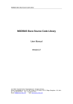
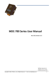
Now you have created a new project with PE support. Under project panel, you can unfold ProcessorExpert.pe and left click
the CPU component, then you will find that CPU properties, methods, events are displayed in the component inspector where
you can configure in a graphical user interface (See Figure 1). For the CPU component, you can configure the following
settings:
1. Clock settings, whether to use internal or external oscillator, which value is used and which system clock you expect to
run at.
2. CPU interrupts, such as NMI interrupts, these are different from peripheral interrupts which are mostly configured in
peripheral components.
3. External bus, configures chip select to use for external devices and what memory map assigned to those external
device.
4. Link file setting, configures memory map for your embedded system, including address range for internal flash,
internal SRAM and it also allows to configure stack and heap size.
Using PE to quickly use common communication interfaces on Kinetis, Rev. 0, 01/2012
2
Freescale Semiconductor, Inc.
PE basics
Figure 1. Component inspector view of CPU
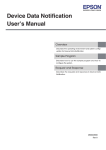
2.2 Adding LDD component
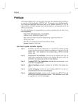
After configuring overall settings for your CPU component, you also need to add peripheral modules in your project so it can
do some useful work. This can be done by adding modules in components library (see Figure 2).
The components in component libraries are grouped into several categories:
• CPU external devices – components for devices externally connected to CPU, such as sensors, memories, displays
• CPU interal peripherals – include components using any of on-chip peripherals of the CPU
• Logic device drivers (LDD) – offer the user the hardware abstraction layer for baremetal applications as well as RTOS
applications
• Operating system – components related to processor expert interaction with OS running on the target
• Software – components encapsulating pure software algorithms
The LDD components are further divided into several sub-catogories based on functions of each group, such as
communication, converter, DMA, human interface, etc. This application note will focus on how to use the communication
LDD component to speed up your design.
Using PE to quickly use common communication interfaces on Kinetis, Rev. 0, 01/2012
Freescale Semiconductor, Inc.
3
PE basics
Figure 2. Components libraries view
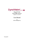
Adding a new LDD component is quite easy, just choose one of the components in component library, right click the
component and choose add to project, then you will see that component displayed under Embedded components, then you
will be able to configure the properties, methods and events of the LDD component the similar to the CPU component (see
Figure 3).
Using PE to quickly use common communication interfaces on Kinetis, Rev. 0, 01/2012
4
Freescale Semiconductor, Inc.
PE basics
Figure 3. Adding a LDD component
2.3 Common things for LDD components
There are some common things among different LDD components, following is a summary.
• Each LDD component includes a Init() method to initialize appropriate peripheral and driver and a Deinit() method to
deinitialize appropriate peripheral and driver.
• The Init() method returns a pointer to driver’s device structure which should be passed as the first parameter for each
component’s method
• The Init() method has one parameter UserDataPtr which can hold user’s own data and this pointer is then returned back
as a parameter in component’s events
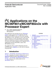
Take the I2C LDD component as an example, first you can configure I2C module properties under component inspector
view, configure things like the following (see Figure 4):
• Whether I2C works as master or slave
• Addressing mode, 7-bit or 10-bit
• Target device slave address, this is slave address of the specific device you are communicating, for example the
MMA7660 accelerometer on TWR-K60N512.
• Pins used for I2C signals, normally pins for one peripheral module can be multiplexed on different package pins, so
here you can select which one according to what you allocated on your board.
• Configure the divide ratio to get your peripheral communcation clock, for example, I2C module is hooked on bus clock
which may be 50 MHz if you run MCU at 100 MHz, so you need to provide the divide ratio to get desired I2C clock,
say 50 kHz.
Using PE to quickly use common communication interfaces on Kinetis, Rev. 0, 01/2012
Freescale Semiconductor, Inc.
5
PE basics
Figure 4. Property configuration for I2C module
Then under Methods and Events page in component inspector (see Figure 5 and Figure 6), you can configure which method
and event handler you want PE to help generate the code template. As you can see, by default PE will choose to generate
basic code for the LDD component. In the case for I2C LDD component, PE generates the following methods and events
handler:
Methods
•
•
•
•
•
•
Init()
Deinit()
MasterSendBlock()
MasterReceiveBlock()
SelectSlaveDevice()
GetError()
Events handler
• OnMasterBlockSent()
• OnMasterBlockReceived()
• OnError()
Of course, you can also select to generate code for more methods or events as you wish. Finally, after you have finished
configuring the I2C LDD components as well as CPU components and there are no configuration errors popped up, you can
right click ProcessorExpert.pe and click Generate Processor Expert Code, then PE will automatically generate initialization
code, component method and event handlers for you.
Using PE to quickly use common communication interfaces on Kinetis, Rev. 0, 01/2012
6
Freescale Semiconductor, Inc.
PE basics
Figure 5. Method page for I2C LDD component
Using PE to quickly use common communication interfaces on Kinetis, Rev. 0, 01/2012
Freescale Semiconductor, Inc.
7
Existing PE sample
Figure 6. Event page for I2C LDD component
2.4 PE generated code for LDD components
There are some common things among different LDD components, following is a summary.
LDD_TDeviceData* I2C_Init(LDD_TUserData *UserDataPtr);
void I2C_Deinit(LDD_TDeviceData *DeviceDataPtr);
LDD_TError I2C_MasterSendBlock(LDD_TDeviceData *DeviceDataPtr, LDD_TData *BufferPtr,
LDD_I2C_TSize Size, LDD_I2C_TSendStop SendStop);
LDD_TError I2C_MasterReceiveBlock(LDD_TDeviceData *DeviceDataPtr, LDD_TData *BufferPtr,
LDD_I2C_TSize Size, LDD_I2C_TSendStop SendStop);
void I2C_OnMasterBlockSent(LDD_TUserData *UserDataPtr);
void I2C_OnMasterBlockReceived(LDD_TUserData *UserDataPtr);
As you can see I2C_Init() receives a pointer in which you can pass user data, it returns a pointer to device data struture. And
I2C_Deinit(),I2C_MasterSendBlock() and I2C_MasterReceiveBlock() all receive the pointer returned from I2C_Init().
3 Existing PE sample
There are plenty of examples on how to use PE LDD components to build up working demos, these demos are very similar
from one to another, so once you learned one example, you can apply to the others.
Using PE to quickly use common communication interfaces on Kinetis, Rev. 0, 01/2012
8
Freescale Semiconductor, Inc.
Existing PE sample
3.1 I2C example
The I2C PE example demonstrates how to use processor expert to generate low level driver code and combine it with higher
level user code to implement read and write to externally connected accelerometer on K60 tower board. This demo uses three
LDD component, that is, I2C, timer and Serial LDD components, serial component is used to implement a user console so we
can print out some message on console with printf, while timer component is used to implement time out mechanism when
reading or writing to accelerometer.
The PE configuration for I2C component is similar as Figure 4, while timer component and serial component configuration is
as shown in Figure 7 and Figure 8, here timer component uses the periodic interrupt timer on Kinetis to implement a 1 second
time interrupt. The serial component uses PTC17 and PTC16 as the UART port and configures UART setting as 38400 8N1,
this UART port actually connects to elevator signals on K60 TWR board and are routed to UART port on TWR-SER board.
For signal connection details, please check the board schematic and user manual for TWR-K60N512.
Figure 7. Timer component configuration
Figure 8. Serial component configuration
Using PE to quickly use common communication interfaces on Kinetis, Rev. 0, 01/2012
Freescale Semiconductor, Inc.
9
Existing PE sample
The main work for the demo is done in the main() function in ProcessorExpert.c file, here it first calls PE_low_level_init()
for common register initialization, then calls each LDD component’s Init() function to initialize that component. This
commonly includes initialization of such things as pin multiplex for modules which have external connections and module
initialization itself like UART baud rate, I2C address, operation mode. After these initialization, we then are able to call
printf or some wrapper functions like ReadAccRegs and WriteAccRegs to access accelerometer.
LDD_TDeviceData *ConsoleUART_Devicedata;
void main(void)
{
LDD_TDeviceData *I2CPtr = NULL;
LDD_TDeviceData *TimerPtr = NULL;
…
//common register initialization, not clock module initialization which is //already done in
__init_hardware before we enter main()
PE_low_level_init();
//initialize UART port such as configure pin multiplex function and UART //registers for a
specific baud rate, this will return a pointer to //LDD_TDeviceData structure
ConsoleUART_DeviceData = ConsoleUART_Init(NULL);
//some printfs to output messages to console
//I2C initialization, similar to serial component
I2CPtr = I2C_Init(&DataState);
//Timer initialization, similar to serial component
TimerPtr = TIMER_Init(NULL);
…
//Register read and write functions we implement for accelerometer, it will //call PE
generated routines of I2C and timer component
ReadAccRegs(I2CPtr, TimerPtr, &DataState, ACC_MODE_REG_ADDR, ACC_REG_SIZE, Data);
WriteAccRegs(I2CPtr, TimerPtr, &DataState, ACC_MODE_REG_ADDR, ACC_REG_SIZE, Data);
…
}
The implementation of ReadAccRegs() and WriteAccRegs() are quite straightforward, it just calls routines generated from
the I2C and timer component. The code for WriteAccRegs() is similar to ReadAccRegs listed here.
static bool ReadAccRegs(LDD_TDeviceData *I2CPtr, LDD_TDeviceData *TimerPtr,
TDataState *DataState, uint8_t Address, uint8_t RegCount, uint8_t *Buffer)
{
DataState->Sent = FALSE;
//Send I2C address
I2C_MasterSendBlock(I2CPtr, &Address, sizeof(Address), LDD_I2C_NO_SEND_STOP);
//Wait till data sent or continue when timeout
while (!DataState->Sent && !Timeout(TimerPtr)) {}
…
//reset timer
TIMER_ResetCounter(TimerPtr);
DataState->Received = FALSE;
//Receive data from device
I2C_MasterReceiveBlock(I2CPtr, Buffer, RegCount, LDD_I2C_SEND_STOP);
//Wait till data received or continue when timeout
while (!DataState->Received && !Timeout(TimerPtr)) {}
…
//reset timer
TIMER_ResetCounter(TimerPtr);
return TRUE;
}
Using PE to quickly use common communication interfaces on Kinetis, Rev. 0, 01/2012
10
Freescale Semiconductor, Inc.
Existing PE sample
3.2 SPI example
The SPI example demonstrates how to use SPI master and SPI slave LDD components to implement communciation between
SPI master and slave. This demo works on TWR-K40X256. You need to connect PTA17, PTA16, PTA15 and PTA14 with
PTE1, PTE3, PTE2 and PTE4 to implement SPI master and slave communication. Figure 9 and Figure 10 are SPI master and
SPI slave component configuration view, here we have configured port used for SPI master as well as bit width of each
transfer, clock phase and polarity, SPI clock speed. While for SPI slave, we just need to configure the same bit width, clock
phase and polarity as SPI master to make sure we get correct data. The APIs generated for SPI master and SPI slave are as
follows. This is similar as that for I2C, it has Init() routine for the component as well as SendBlock() and ReceiveBlock()
routine for sending and receiving data on SPI master or slave. It also includes GetBlockSentStatus() and
GetBlockReceivedStatus() routines for checking whether data sending and receiving has finished or not.
//SPI master
LDD_TDeviceData* SM1_Init(LDD_TUserData *UserDataPtr);
LDD_TError SM1_ReceiveBlock(LDD_TDeviceData *DeviceDataPtr, LDD_TData *BufferPtr, uint16_t
Size);
LDD_TError SM1_SendBlock(LDD_TDeviceData *DeviceDataPtr, LDD_TData *BufferPtr, uint16_t
Size);
bool SM1_GetBlockSentStatus(LDD_TDeviceData *DeviceDataPtr);
bool SM1_GetBlockReceivedStatus(LDD_TDeviceData *DeviceDataPtr);
//SPI slave
LDD_TDeviceData* SS1_Init(LDD_TUserData *UserDataPtr);
LDD_TError SS1_ReceiveBlock(LDD_TDeviceData *DeviceDataPtr, LDD_TData *BufferPtr, uint16_t
Size);
LDD_TError SS1_SendBlock(LDD_TDeviceData *DeviceDataPtr, LDD_TData *BufferPtr, uint16_t
Size);
bool SS1_GetBlockSentStatus(LDD_TDeviceData *DeviceDataPtr);
bool SS1_GetBlockReceivedStatus(LDD_TDeviceData *DeviceDataPtr);
The main() function implementation is also similar as I2C example. Main flow is as follows:
LDD_TDeviceData *ConsoleUART_DeviceData;
void main(void)
{
LDD_TDeviceData *slaveDevData;
LDD_TDeviceData *masterDevData;
//common register initialization
PE_low_level_init();
//Call Init() routine for each component
ConsoleUART_DeviceData = ConsoleUART_Init(NULL);
masterDevData = SM1_Init(NULL);
slaveDevData = SS1_Init(NULL);
//some printfs to output message on console
//Call SendBlock(), ReceiveBlock(), GetBlockSentStatus() and //GetBlockReceivedStatus() here
for either SPI master or slave
…
}
Using PE to quickly use common communication interfaces on Kinetis, Rev. 0, 01/2012
Freescale Semiconductor, Inc.
11
Existing PE sample
Figure 9. SPI master component configuration
Figure 10. SPI slave component configuration
Using PE to quickly use common communication interfaces on Kinetis, Rev. 0, 01/2012
12
Freescale Semiconductor, Inc.
Conclusion
4 Conclusion
Processor expert is a quite user friendly tool which helps you configure hardware operation in a GUI interface and generate
useful APIs which you can use in your application. With the included logic device component (LDD), you can quickly
generate driver code for nearly every available modules on Kinetis after you configured the component according to
hardware connections on your board and required operation details of the module. You can use the PE examples installed
under Codewarrior folder as a starting point and implement your desired function by just calling the generated APIs from PE.
Using PE to quickly use common communication interfaces on Kinetis, Rev. 0, 01/2012
Freescale Semiconductor, Inc.
13
How to Reach Us:
Home Page:
www.freescale.com
Web Support:
http://www.freescale.com/support
USA/Europe or Locations Not Listed:
Freescale Semiconductor
Technical Information Center, EL516
2100 East Elliot Road
Tempe, Arizona 85284
+1-800-521-6274 or +1-480-768-2130
www.freescale.com/support
Europe, Middle East, and Africa:
Freescale Halbleiter Deutschland GmbH
Technical Information Center
Schatzbogen 7
81829 Muenchen, Germany
+44 1296 380 456 (English)
+46 8 52200080 (English)
+49 89 92103 559 (German)
+33 1 69 35 48 48 (French)
www.freescale.com/support
Japan:
Freescale Semiconductor Japan Ltd.
Headquarters
ARCO Tower 15F
1-8-1, Shimo-Meguro, Meguro-ku,
Tokyo 153-0064
Japan
0120 191014 or +81 3 5437 9125
[email protected]
Asia/Pacific:
Freescale Semiconductor China Ltd.
Exchange Building 23F
No. 118 Jianguo Road
Chaoyang District
Beijing 100022
China
+86 10 5879 8000
[email protected]
For Literature Requests Only:
Freescale Semiconductor Literature Distribution Center
1-800-441-2447 or +1-303-675-2140
Fax: +1-303-675-2150
[email protected]
Document Number: AN4450
Rev. 0, 01/2012
Information in this document is provided solely to enable system and software
implementers to use Freescale Semiconductors products. There are no express or implied
copyright licenses granted hereunder to design or fabricate any integrated circuits or
integrated circuits based on the information in this document.
Freescale Semiconductor reserves the right to make changes without further notice to any
products herein. Freescale Semiconductor makes no warranty, representation, or
guarantee regarding the suitability of its products for any particular purpose, nor does
Freescale Semiconductor assume any liability arising out of the application or use of any
product or circuit, and specifically disclaims any liability, including without limitation
consequential or incidental damages. "Typical" parameters that may be provided in
Freescale Semiconductor data sheets and/or specifications can and do vary in different
applications and actual performance may vary over time. All operating parameters,
including "Typicals", must be validated for each customer application by customer's
technical experts. Freescale Semiconductor does not convey any license under its patent
rights nor the rights of others. Freescale Semiconductor products are not designed,
intended, or authorized for use as components in systems intended for surgical implant
into the body, or other applications intended to support or sustain life, or for any other
application in which failure of the Freescale Semiconductor product could create a
situation where personal injury or death may occur. Should Buyer purchase or use
Freescale Semiconductor products for any such unintended or unauthorized application,
Buyer shall indemnify Freescale Semiconductor and its officers, employees, subsidiaries,
affiliates, and distributors harmless against all claims, costs, damages, and expenses, and
reasonable attorney fees arising out of, directly or indirectly, any claim of personal injury
or death associated with such unintended or unauthorized use, even if such claims alleges
that Freescale Semiconductor was negligent regarding the design or manufacture of
the part.
RoHS-compliant and/or Pb-free versions of Freescale products have the functionality and
electrical characteristics as their non-RoHS-complaint and/or non-Pb-free counterparts.
For further information, see http://www.freescale.com or contact your Freescale
sales representative.
For information on Freescale's Environmental Products program, go to
http://www.freescale.com/epp.
Freescale™ and the Freescale logo are trademarks of Freescale Semiconductor, Inc.
All other product or service names are the property of their respective owners.
© 2012 Freescale Semiconductor, Inc.