1
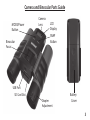
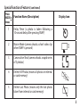
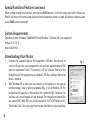
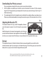
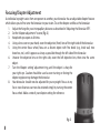
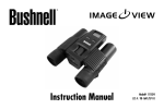
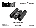
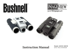
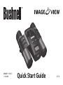
Model#: 111024/
111024ML
Quick Start Guide
07-10
Camera and Binocular Parts Guide
MODE/Power
Button
Binocular
Focus
Camera
Lens
LCD
Display
SNAP
Button
USB Port
SD Card Slot
Diopter
Adjustment
Battery
Cover
3
Basic Setup
1.
2.
3.
4.
The camera is powered by two AAA batteries (not included). Insert batteries into the compartment,
using the polarity marks inside for reference. A power meter on the top right of the display indicates
battery condition.
Insert an SD card (“upside down” with metal contacts facing up) in the slot if greater storage is desired.
An SD card icon will appear at the top right corner of the LCD display. You may use SD cards (not MMC
cards) up to 2 GB capacity. If no card is inserted, the camera will store photos in its internal memory.
When the internal or card memory is full, and can hold no more photos, the display will indicated “FUL”.
Press and release the MODE (Power) button to turn on the camera. The camera will turn off
automatically after about two minutes if no buttons are pressed. To turn the camera off manually, press
and hold the MODE button until the display goes out. Note: when the camera is connected to a computer
via the supplied USB cable, the camera will power on automatically, and draw its power from the computer
with no battery drain.
Hold the ImageView steady and press SNAP to take a picture. The camera focus is preset to take sharp
photos of subjects about 50 feet or farther away.
Special Functions/Features
There are several functions/features that can be accessed by pressing the MODE button one or more times
after the camera has been turned on to select the function, then pressing SNAP to confirm and execute the
function. If you do not press the SNAP button to confirm/execute the selected function (while the icon for
that function is displayed) within 5 seconds, the function is cancelled and the camera will return to normal
operating mode. The functions and their display icons are:
4
Special Functions/Features (continued)
Press
MODE x
times
Function Name (Description)
1
Delay Timer (a photo is taken following a
10-second delay after pressing SNAP)
2
Movie Mode (camera shoots a short video clip
when SNAP is pressed)
3
Consecutive Shot (camera shoots a rapid series
of 3 photos)
4
Delete All Photos (erases all photos in internal
or card memory)
5
Delete Last Photo (erases only the last photo
taken from internal or card memory)
Display Icon
5
Special Functions/Features (continued)
When cycling through the functions, pressing the MODE button a sixth time (once more after “Delete Last
Photo”) will return the camera and display to normal operating mode (a single still photo is taken as soon
as the SNAP button is pressed).
System Requirements
Operating System: Windows® 2000/ME/XP/Vista/Windows 7 (Windows 98 is not supported)
or Mac OS 9 / OS X
Internal USB Port
Downloading Your Photos
1.
2.
6
Connect the supplied cable to the ImageView’s USB port, then directly to
a main USB port on your computer-do not use front panel/keyboard USB
ports or unpowered “hubs”. The camera’s LCD will indicate “Sto”, and the
ImageView will be recognized as a standard “USB Mass Storage” device-no
driver is needed.
With Windows XP or later, you can simply use the options in the pop-up
window to copy, view, or print your photos (Fig. 1). On all Windows OS, the
ImageView will appear as a “Removable Disk” under the “My Computer” list
(on Macs, an icon will appear on your desktop). The ImageView’s photo files
are named “IMG_0001.JPG” etc, and are located in the “DCIM” folder on this
“Removable Disk”. You may copy them to your hard drive as you would any
Fig. 1
Downloading Your Photos (continued)
3.
4.
file-just copy/paste or drag the file names or icons to your drive or desktop.
After the photos are copied to your hard drive, you can disconnect the camera. (On Mac computers,
drag the “disk” that appeared on your desktop when the camera was connected into your Trash to “eject” it
before disconnecting.)
The standard jpg files from the ImageView may be edited with any photo software you choose to use.
Photos may also be downloaded by removing the card and using any USB card reader with an SD slot.
Adjusting the Binocular IPD
Fig. 2
The distance between the eyes, called “interpupillary distance,”
varies from person to person. To set the hinge for your personal
IPD:
Hold the binocular in the normal viewing position, with a firm grip
on each side. Move the barrels closer together or further apart (Fig.
2) until you see a single circular field. Always re-set your binocular to this position before using.
Eyecups
The ImageView binocular is fitted with rubber roll-down eyecups designed for your comfort and to
exclude extraneous light. If you wear glasses, roll down the eyecups. This will bring your eyes closer to the
binocular lens so you can view the entire image without any cutoff.
Windows is a registered trademark of Microsoft Corporation in the United States and other countries.
Mac and Mac OS are trademarks of Apple Inc., registered in the U.S. and other countries.
7
Focusing/Diopter Adjustment
As individual eyesight varies from one person to another, your binocular has an adjustable diopter feature
which allows you to fine-tune the binocular to your vision. To set the diopter and focus the binocular:
1. Adjust the hinge for your interpupillary distance as described in “Adjusting the Binocular IPD”.
2. Set the “diopter adjustment” to zero (Fig. 3).
3. Keep both eyes open at all times.
4. Using a lens cover or your hand, cover the objective (front) lens of the right side of the binocular.
5. Using the center focus wheel, focus on a distant object with fine detail (e.g., brick wall, tree
branches, etc.) until it appears as sharp as possible through the left side of the binocular.
6. Uncover the objective lens on the right side, cover the left objective lens, then view the same
object.
7. Turn the “diopter setting” adjustment ring, until the object is sharp for
your right eye. Caution should be used as over turning or forcing the
diopter eyepiece may damage the binocular.
8. Your binocular should now be adjusted for your eyesight. Focus at any
far or near distances can now be attained simply by turning the center
focus wheel. Make a note of your diopter setting for reference.
Fig. 3
8
TWO-Year LIMITED WARRANTY
Your Bushnell® product is warranted to be free of defects in materials and workmanship for two years after the date of
purchase. In the event of a defect under this warranty, we will, at our option, repair or replace the product, provided that you
return the product postage prepaid. This warranty does not cover damages caused by misuse, improper handling, installation,
or maintenance provided by someone other than a Bushnell Authorized Service Department.
Any return made under this warranty must be accompanied by the items listed below:
1) A check/money order in the amount of $10.00 to cover the cost of postage and handling
2) Name and address for product return
3) An explanation of the defect
4) Proof of Date Purchased
5) Product should be well packed in a sturdy outside shipping carton, to prevent damage in transit, with return postage
prepaid to the address listed below:
IN U.S.A. Send To: IN CANADA Send To:
Bushnell Outdoor Products
Bushnell Outdoor Products
Attn.: Repairs
Attn.: Repairs
9200 Cody
25A East Pearce Street, Unit 1
Overland Park, Kansas 66214
Richmond Hill, Ontario L4B 2M9
This warranty gives you specific legal rights.
You may have other rights which vary from country to country.
©2010 Bushnell Outdoor Products
9
FCC Compliance Statement:
This equipment has been tested and found to comply with the limits for a Class B digital device, pursuant to part 15
of the FCC Rules. These limits are designed to provide reasonable protection against harmful interference in a residential
installation.
Operation is subject to the following two conditions: (1) This device may not cause harmful interference, and (2) this device
must accept any interference received, including interference that may cause undesired operation.
This equipment generates, uses and can radiate radio frequency energy and, if not installed and used in accordance with the
instructions, may cause harmful interference to radio communications. However, there is no guarantee that interference will
not occur in a particular installation. If this equipment does cause harmful interference to radio or television reception, which
can be determined by turning the equipment off and on, the user is encouraged to try to correct the interference by one or
more of the following measures:
· Reorient or relocate the receiving antenna.
· Increase the separation between the equipment and receiver.
· Connect the equipment into an outlet on a circuit different from that to which the receiver is connected.
· Consult the dealer or an experienced radio/TV technician for help.
The device does not contain any user-serviceable parts. Repairs should only be made by an Authorized Bushnell repair center.
Unauthorized repairs or modifications could result in permanent damage to the equipment, and will void your warranty and
your authority to operate this device under Part 15 regulations.
The shielded interface cable which is provided must be used with the equipment in order to comply with the limits for a digital
device pursuant to Subpart B of Part 15 of FCC Rules.
10
For further questions or additional information please contact:
Bushnell Outdoor Products
9200 Cody, Overland Park, Kansas 66214
(800) 423-3537 • www.bushnell.com
©2010 Bushnell Outdoor Products