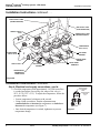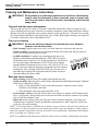
1
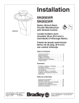
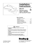
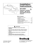
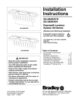
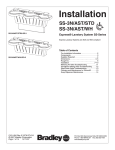
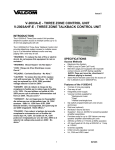
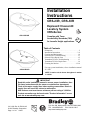
Installation
Instructions
CRS-2/IR, CRS-3/IR
A
Complies with Texas
Accessibility Standards (TAS)
for Juvenile Height applications.
•COM
CRS-3/IR/LSD
DA
Express® Crescent®
Lavatory System
CRS-Series
PL
IANT
TAS
Table of Contents
Dimensions . . . . . . . . . . . . . . . . . . . . . . . . . . . . . . . .2
Installation Instructions . . . . . . . . . . . . . . . . . . . . . 3–9
Cleaning and Maintenance . . . . . . . . . . . . . . . . . . . .10
Solenoid Valve Troubleshooting . . . . . . . . . . . . . . .11
Solenoid Valve Repair Parts . . . . . . . . . . . . . . . . . .12
Vernatherm™ Valve Troubleshooting . . . . . . . . . . .13
Vernatherm™ Valve Repair Parts . . . . . . . . . . . . . .14
Cleaning the Strainer . . . . . . . . . . . . . . . . . . . . .13-14
For soap system installation, refer to installation manual
215-1583
CRS-2/IR/LSD
NOTE: 3-station unit is shown throughout. 2-station
is similar.
IF IE
D PRO
D
U
NAHB
RESEARCH
-4
0
R
C E N TE R
c.
or
g
C
RT
CT
UP
C
49
-2
3 01
215-1330 Rev. K; EN 06-915
© 2007 Bradley Corporation
Page 1 of 14 2/8/07
CE
IMPORTANT
Read this entire installation manual to ensure proper installation, then
file these instructions with the owner or maintenance department.
Flush all the water supply lines before making connections. Debris in
supply lines will cause the valves to malfunction.
Wall anchors used must have a minimum pull-out rating of 1,000 lbs.
Product warranties may be found under "Product Information" on our
web site at www.bradleycorp.com.
00
br
ah
www.n
P.O. Box 309, Menomonee Falls, WI 53052-0309
TEL. 1-800-BRADLEY FAX 262-251-5817
http://www.bradleycorp.com
Express® Crescent® Lavatory System - CRS-Series
CRS-2/IR, CRS-3/IR
Installation Instructions
Express® Crescent® Lavatory System Dimensions
48"
(1219)
(mm)
3-3/8"
(86)
14"
(356)
48"
(1219)
17-3/8"
(441)
(mm)
26"
(660)
26"
(660)
(mm)
8-1/2"
(216)
* ADJUSTMENTS TO VERTICAL DIMENSIONS
FOR VARIOUS RIM HEIGHTS
Rim Height
*37-3/8"
(949)
*34"
(864)
*20"
(508)
None, as shown
32"
TAS Ages 11 thru
14 or 15, Grades 6
thru 8 or 9
Subtract 2"
30"
TAS Ages 4 thru
10 or 11, Grades:
Pre-K thru 5 or 6 &
Proposed Juvenile
Height ADA
Subtract 4"
24"
Preschool (required Subtract 10"
by some local
codes)
A
•COM
2
IANT
2/8/07
Adjustment
Adult Height ADA,
TAS Adult Height
DA
PL
Application
34"
Bradley Corporation • 215-1330 Rev. K; EN 06-915
Express® Crescent® Lavatory System - CRS-Series
CRS-2/IR, CRS-3/IR
Installation Instructions
Installation Instructions
Supplies required for installation:
•
•
•
•
•
•
(6) 3/8" wall anchors, bolts and washers to mount bowl to wall (min. pull-out force of 1,000 lbs.)
1/2" NPT hot and cold or tempered supply piping
1-1/2" drain piping and P-Trap (available from Bradley, p/n 269-1697)
110 VAC power source for 110/24 VAC plug-in transformer supplied
OPTIONAL TRAP COVER: 1/4" wall anchor, bolt and washer to mount trap cover to wall
OPTIONAL: Bradley recommends installing an electrical cut-off switch to the unit (this feature
prevents accidental water delivery during regular maintenance and service)
Step 1: Rough-ins
NOTE: Refer to Figure 1 below and Figure 2 on page 4 for Express® Crescent® Lavatory System
rough-ins and dimensions.
1. Rough in 1/2" NPT hot and cold supply lines and 1-1/2" NPT drain waste connection through
wall at dimensions shown in Figure 1.
IMPORTANT: Flush all the water supply lines before making connections. Debris in
supply lines will cause the valves to malfunction.
Standard Height Mounting
2"
(51mm)
6-1/2"
(165mm)
RIM
HEIGHT
34"
(864mm)*
25-5/8"
(651mm)*
TRAP COVER
(OPTIONAL)
23-3/4"
(603mm)*
1/2" NPT DRAIN
STUB OUT 2" (51mm)
1/2" NPT HOT AND
COLD SUPPLIES
STUB OUT 2" (51mm)
CENTERLINE
OF FIXTURE
Figure 1
FLOOR
* ADJUSTMENTS TO VERTICAL DIMENSIONS FOR VARIOUS RIM HEIGHTS
Rim Height
Application
Adjustment
34"
Adult Height ADA, TAS Adult Height TAS Adult Height
None, as shown
32"
TAS Ages 11 thru 14 or 15, Grades 6 thru 8 or 9
Subtract 2"
30"
TAS Ages 4 thru 10 or 11, Grades: Pre-K thru 5 or 6
& Proposed Juvenile Height ADA
Subtract 4"
24"
Preschool (required by some local codes)
Subtract 10"
Bradley Corporation • 215-1330 Rev. K; EN 06-915
2/8/07
3
Express® Crescent® Lavatory System - CRS-Series
CRS-2/IR, CRS-3/IR
Installation Instructions
Installation Instructions continued . . .
Step 1: Rough-ins cont’d.
2. Install a 110 volt GFI protected electrical outlet per local code at the location shown in Figure 2.
3. Install six 3/8" wall anchors with a minimum pull-out rating of 1,000 lbs. (supplied by installer)
at the locations marked in Figure 2.
4. OPTIONAL TRAP COVER: Install one 1/4" wall anchor at the location marked in Figure 2.
Standard Height Mounting
10"
(254mm)
3/8" WALL ANCHORS (6) PLACES, MIN. PULL-OUT
FORCE 1,000 LBS. PER ANCHOR
10"
(254mm)
10"
(254mm)
13-1/2"
(343mm)
10"
(254mm)
13-1/2"
(343mm)
1-3/8" (35mm)
33-1/2"
(851mm)*
3-3/4"
(45mm)
31"
(788mm)*
(4) 1/4" WALL
ANCHORS FOR
OPTIONAL
SOAP SYSTEM
35"
(889mm)*
7-11/16"
(195mm)
10-1/2"
(267mm)
22-3/4"
(578mm)*
27-1/4"
(692mm)*
110 volt GFCI PROTECTED
ELECTRICAL OUTLET
(RECOMMENDED LOCATION)
(CHECK LOCAL ELECTRICAL
CODES BEFORE ROUGHING IN)
OPTIONAL 1/4" WALL
ANCHOR FOR TRAP
COVER (USE TRAP
COVER FOR TEMPLATE)
CL
FLOOR
Figure 2
* ADJUSTMENTS TO VERTICAL DIMENSIONS FOR VARIOUS RIM HEIGHTS
Rim Height
4
Application
Adjustment
34"
Adult Height ADA, TAS Adult Height TAS Adult Height
None, as shown
32"
TAS Ages 11 thru 14 or 15, Grades 6 thru 8 or 9
Subtract 2"
30"
TAS Ages 4 thru 10 or 11, Grades: Pre-K thru 5 or 6
& Proposed Juvenile Height ADA
Subtract 4"
24"
Preschool (required by some local codes)
Subtract 10"
2/8/07
Bradley Corporation • 215-1330 Rev. K; EN 06-915
Installation Instructions
Express® Crescent® Lavatory System - CRS-Series
CRS-2/IR, CRS-3/IR
Installation Instructions continued . . .
Step 3: Install wall anchors
1. Measure and mark the centerline of the lavatory system on the wall.
3. Using cardboard template 186-1311 provided, mark six mounting holes on wall.
3. Drill holes in the wall and install the six 3/8" wall anchors with a minimum pull-out rating of 1,000
lbs. (supplied by installer) at the locations shown in Figure 1 on page 3.
NOTE: The six 3/8" anchors will be used to mount the Crescent® bowl to the wall.
4. OPTIONAL TRAP COVER: Install the 1/4" wall anchor for the Trap Cover (supplied by
installer) as shown on Figure 1. Use Trap Cover to locate.
5. OPTIONAL SOAP TANK: Install 1/4" anchors for soap tank installation (refer to soap system
installation manual #215-1583 for further instructions).
Step 4: Remove cover from bowl assembly
1.
2.
3.
4.
Unpack the bowl and cover assembly.
Remove the wing nuts on the two threaded rods which retain the cover (see Figure 3).
Remove the top cover bracket.
Lift the cover off and set aside.
Step 5: Mount the bowl to the wall
WARNING: Do not attempt to install the bowl by yourself. To prevent serious
injury, install the bowl with the assistance of another person and
always use appropriate lifting procedures.
1. With someone to assist you, move the bowl assembly to the wall using appropriate lifting
procedures, secure the bowl to the wall.
2. Level the bowl assembly with shims if necessary and then tighten anchors.
TOP COVER
THREADED ROD
330-078
TOP COVER BRACKET
(140-852)
Figure 3
Bradley Corporation • 215-1330 Rev. K; EN 06-915
WING NUT
(161-076)
2/8/07
5
Express® Crescent® Lavatory System - CRS-Series
CRS-2/IR, CRS-3/IR
Installation Instructions continued . . .
Step 6: Install drain spud
1. Assemble the P-trap by (supplied by installer)
connecting the 1-1/2" tubular pipe to the 1-1/4"
tailpiece and to the 1-1/2" drain pipe stubbed out
of the wall (see Figure 4).
Installation Instructions
DRAIN ASSEMBLY
STRAINER
AND
TAILPIECE
269-1584
1/4" RUBBER
WASHER
FIBER
WASHER
NUT
Step 7: Connecting Supply
1. Connect the 1/2" NPT female end of the
stop/check valves to the rough-ins.
2. Connect one end of the supply hoses to the
stop/check valves.
TRIM TO FIT
IMPORTANT: The hose attached to the hot
P-TRAP
(polypropylene)
water inlet of the Vernatherm™
269-1697
Figure 4
TMV valve must be connected
to the hot water rough-in.
3. Connect the other end of the supply hoses to the Vernatherm™ TMV valve assembly.
4. OPTIONAL SINGLE-TEMPERED SUPPLY: Attach the stop/check valve to the 1/2" tempered
supply line. Connect the stop/check valve to the solenoid valve with the flexible supply hose.
NOTE: The thermostatic mixing valve requires at least 115° F water from the hot water side for
proper operation. As with all lavatories, there will be a delay in obtaining warm water. If the hot
water is too far away from the washfountain, a circulating pump may be required.
VERNATHERM™
MIXING VALVE
COLD SUPPLY INLET
HOT
SUPPLY
COLD
SUPPLY
VALVE
MOUNTING
BRACKET
STOP/CHECK
VALVE
VERNATHERM™
MIXING VALVE
HOT SUPPLY INLET
FLEXIBLE
SUPPLY HOSE
Figure 5
6
2/8/07
Bradley Corporation • 215-1330 Rev. K; EN 06-915
Express® Crescent® Lavatory System - CRS-Series
CRS-2/IR, CRS-3/IR
Installation Instructions
Installation Instructions continued . . .
Step 8: Electrical and supply connections
NOTE: Refer to Figure 6a below for CRS-2/IR or Figure 6b on page 8 for CRS-3/IR.
WARNING:
The Adaptive® Infrared control must be connected with a 24 VAC
Class II transformer. Connections to 110 VAC will result in damage to
the electronics and can cause personal injury.
CAUTION:
Connection of leads other than shown may cause permanent damage
to the sensor.
NOTE: Compliance and conformity to local codes and ordinance is the responsibility of the installer.
NOTE: The solenoid valves have been pre-wired.
1. Snap the senser circuit plug from the bowl into the solenoid circuit plug located on the valve bracket.
2. Snap the transformer circuit plug into the female transformer circuit plug located on the valve bracket.
3. Turn on the water supply to the Express® Crescent® Lavatory System and check for leaks.
4. Plug in the transformer and wait at least two minutes to allow the sensor to adapt to the environment.
5. Pass your hand in front of each station’s sensor until all the air is purged from the lines and water
is flowing smoothly.
NOTE: The Vernatherm mixing valve is NOT factory preset. Upon installation, the temperature of this
valve must be checked and adjusted to ensure delivery of a safe water temperature. Water in excess of
110°F (43°C) may cause scalding.
GREEN SUPPLY TUBE
(FROM SPRAYHEAD)
RED SUPPLY TUBE
(FROM SPRAYHEAD)
SENSOR CIRCUIT PLUG
COMPRESSION NUT
(110-231)
TRANSFORMER
CIRCUIT PLUG
RED SPADE TERMINAL
WHITE SPADE TERMINAL
GREEN SPADE TERMINAL
Figure 6a
Bradley Corporation • 215-1330 Rev. K; EN 06-915
2/8/07
7
Express® Crescent® Lavatory System - CRS-Series
CRS-2/IR, CRS-3/IR
Installation Instructions
Installation Instructions continued . . .
BLACK SUPPLY TUBE
(FROM SPRAYHEAD)
RED SUPPLY TUBE
(FROM SPRAYHEAD)
SENSOR CIRCUIT
PLUG
GREEN SUPPLY TUBE
(FROM SPRAYHEAD)
COMPRESSION
NUT (110-231)
TRANSFORMER
CIRCUIT PLUG
RED SPADE
TERMINAL
GREEN SPADE
TERMINAL
SUPPLY INLET
WHITE SPADE
TERMINALS
BLACK SPADE
TERMINAL
VERNATHERM™
THERMOSTATIC
MIXING VALVE
Figure 6b
Installation Instructions continued . . .
Step 8: Electrical and supply connections, cont’d.
6. Check the temperature when approximately 1.0 GPM water flow
is reached and adjust if necessary (the range of the valve is
95°F–115°F (35°C–43°C). To adjust the temperature, follow the
procedure below:
• Loosen temperature locking nut with wrench.
• Using a blade screwdriver, turn the adjustment stem
counterclockwise to increase the temperature or clockwise to
decrease the temperature (see Figure 7).
• Once desired temperature is reached, tighten nut to prevent
temperature change.
8
2/8/07
TEMPERATURE
ADJUSTMENT
STEM
TEMPERATURE
LOCKING
NUT
Figure 7
Bradley Corporation • 215-1330 Rev. K; EN 06-915
Installation Instructions
Express® Crescent® Lavatory System - CRS-Series
CRS-2/IR, CRS-3/IR
Installation Instructions continued . . .
Step 9: Install the Optional Soap Dispenser
For Express® Crescent® Lavatory System units with optional soap dispensers, see 215-1583.
Step 10: Install the top cover
1. Carefully place the top cover on top of the lavatory system bowl.
2. Install the threaded rods into the holes on the bottom of the top cover (see Figure 3 on page 5).
3. Slide the anchor plate onto the threaded rods and secure anchor plate against bowl using the
wing nuts provided.
4. OPTIONAL SOAP DISPENSER: Install soap filler assembly in mounting bracket previously
installed. Tighten the optional soap filler cap nut with a spanner wrench.
Bradley Corporation • 215-1330 Rev. K; EN 06-915
2/8/07
9
Express® Crescent® Lavatory System - CRS-Series
CRS-2/IR, CRS-3/IR
Installation Instructions
Cleaning and Maintenance Instructions
IMPORTANT: Strong alkaline or acid-based chemicals and cleansers should not be
used to clean the Crescent®. If these chemicals come in contact with
the Terreon® surface, wipe off the surface immediately and flush with
soapy water.
Terreon® and trap cover maintenance
The bowl and top cover are made of Terreon®, a densified solid surface material composed of an
acrylic modified polyester resin. Terreon® is resistant to chemicals, stains, burns and impact. Surface
damage can easily be repairable with everyday cleaners or fine grit abrasives. The trap cover is made
of vacuum-formed ABS plastic and will not chip, peel or flake. With regular cleaning, your Express®
Crescent® will provide years of dependable service.
Trap cover cleaning
IMPORTANT: Do not use abrasive cleansers to clean the trap cover. Abrasive
cleaners can mar the surface.
• Daily cleaning: Wipe the trap cover with a wet cloth, then rinse with water and wipe dry.
• Weekly cleaning: Give the trap cover a thorough cleaning with a liquid tub and tile cleaner to
remove soil and maintain the glossy finish.
• Graffiti/Vandalism: If vandals create markings on the trap cover,
Bradley recommends using Motsenbocker’s LIFT OFF® to remove
ink and spray paint. Remover #3 is for ink and markers, and Remover
#4 is for spray paint. Motsenbocker’s LIFT OFF® can be ordered
through Sanitary Maintenance Service, Inc. (call 1-800-451-5523, ext.
425, or visit www.sanitarymaintenance.com/product.htm for ordering
information). After cleaning with LIFT OFF®, give the trap cover a
final thorough cleaning with a liquid tub and tile cleaner to remove
soil and maintain the glossy finish.
R'S
CKE
O
B
N
E
S
T
MO
R
Bowl and cover cleaning
• Daily cleaning: Wipe the unit with a damp cloth and then wipe dry.
• Weekly cleaning: Wipe the surface with a damp cloth and a household liquid detergent. Stubborn
stains can be removed as follows:
1. Using a #7448 Scotch-Brite™ pad, scrub with an abrasive cleanser (such as Ajax®,
Comet® or Soft Scrub®) and water.
2. Clean thoroughly with soapy water and allow to dry.
• Scorch marks: Although Terreon® will not burn, a lit cigarette in contact with Terreon® could
leave a scorch mark. Scorch marks can be removed with either an abrasive cleaner or by buffing
with a #7448 Scotch-Brite™ pad.
• Repair kit: In the unlikely event your Terreon® surface becomes damaged, it can easily and
inexpensively be repaired. Contact your Bradley representative to order a repair kit and be sure
to specify color when ordering.
NOTE: Use of brand names is intended only to indicate a type of cleaner. This does not constitute an
endorsement, nor does the omission of any brand name cleaner imply its inadequacy. Many products
named are regional in distribution and can be found in local supermarkets, department and hardware
stores or through your cleaning service.
NOTE: It is emphasized that all products should be used in strict accordance with package instructions.
10
2/8/07
Bradley Corporation • 215-1330 Rev. K; EN 06-915
Express® Crescent® Lavatory System - CRS-Series
CRS-2/IR, CRS-3/IR
Installation Instructions
Solenoid Valve Troubleshooting
CAUTION:
Problem:
Cause:
Solution:
Turn off water supplies to unit before troubleshooting.
An individual operating station fails to shut off and drips.
There is debris trapped between the diaphragm and the valve seat.
Remove debris between diaphragm and the valve seat.
1. Remove the three #8 Phillips-head screws that hold the solenoid valve assembly together. Be
careful not to lose the armature or spring (see Figure 8 on page 12).
2. Remove the diaphragm. Remove any particles that have been trapped between the diaphragm
and the valve seat. Rinse off the diaphragm and inspect for damage. Make sure the center orifice
and both small side orifices are open.
3. Reassemble in reverse order, being careful not to overtighten the Phillips-head screws or you
may crack the plastic valve body. Tighten until the armature plate makes contact with the plastic
body.
4. Reconnect the wiring per diagram on page 7 (for CRS-2/IR) or page 8 (for CRS-3/IR).
Problem:
An individual operating station fails to turn on.
Cause:
A failed coil for the valve or loose electrical connection to the terminal.
Solution:
Test the station to determine cause.
1. Disconnect the wires from the coil of an adjacent valve. Disconnect the wires from the problem
valve and reconnect to the adjacent valve.
2. Turn on electrical and water supplies to the unit. Pass your hand in front of the sensor of the
problem station, and the adjacent station should turn on.
If the adjacent station turns on and cycles normally, replace the coil on the problem valve.
If the adjacent valve fails to turn on, inspect the wires from the sensor cable and do the following:
• make sure there are no breaks and that the fully insulated disconnect terminals are firmly
crimped in place;
• turn off the electrical and water supplies;
• reconnect to the adjacent valve and turn on the water supplies to the unit;
• pass your hand in front of the sensor. If the station still fails to turn on, replace the sensor.
Bradley Corporation • 215-1330 Rev. K; EN 06-915
2/8/07
11
Express® Crescent® Lavatory System - CRS-Series
CRS-2/IR, CRS-3/IR
Installation Instructions
Solenoid Valve S07-067 (closed body) and S07-067A (thru body)
REF.
1
1
8
2
3
4
5
6
7
8
9
7
8
QTY.
1
1
1
1
1
1
1
1
3
1
PART NO.
118-307
118-307A
269-983
269-577
269-578
269-1729
269-1730
269-579
160-447
125-165
DESCRIPTION
VALVE BODY, 1/4" CLOSED
VALVE BODY, 1/4" THRU
DIAPHRAGM
ARMATURE
SPRING
ARMATURE HOUSING
CLAMP, ARMATURE HOUSING
COIL, SOLENOID VALVE
SCREW, #8 X 5/8
O-RING, #2-013
6
5
4
3
2
1
9
Figure 8
12
2/8/07
Bradley Corporation • 215-1330 Rev. K; EN 06-915
Installation Instructions
Express® Crescent® Lavatory System - CRS-Series
CRS-2/IR, CRS-3/IR
Thermostatic Mixing Valve Troubleshooting
NOTE: Before attempting to troubleshoot the valve or disassemble the components, check for the
following conditions:
• If stop/check valves are used, make sure that they are fully open.
• Make sure that the hot and cold inlet pipes are connected properly, and that there are no crossconnections or leaking stop/check valves.
• Check the hot water heater output to make sure that it is at least 20° F above the set
temperature.
Be sure to close the appropriate shut-off valves prior to disassembly of the valve and reopen the
valves after inspection and repair is complete.
Problem: Limited water flow
Cause: Dirt and debris have built up in the valve or strainer.
1. Remove and clean strainer (see Figure 9 or 10 on page 14). If strainer needs to be replaced, order
Bradley part number 173-028.
2. Check the piston for smooth movement.
To check the valve's piston for free and smooth movement, follow the procedures outlined below:
1. Remove the valve's cap and thermostat (see Figure 9 on Page 14).
2. Push down on the piston with your finger (the piston should move freely). If the movement is
not as it should be, the piston needs to be cleaned. Follow the method outlined below for
cleaning the piston and valve body:
• Remove the thermostat.
• Lift the piston out with a needle-nose pliers and remove the spring.
• Any cleaner suitable for brass and stainless steel may be used (if cleaning with suitable cleaner
is not sufficient to remove debris, a 400-grit sandpaper may be used to polish and hone the
piston and valve body).
• Snap spring into piston (will detent) and reassemble into the valve body. Retest the piston.
3. If, after a thorough cleaning, the piston does not move freely, the piston must be replaced.
Contact your Bradley representative and ask for Repair Kit (part number S65-259).
Problem: External leaks in the system
Cause: O-rings have been damaged.
Solution: Replace O-rings where necessary. For replacement of the O-rings, contact your
Bradley representative and ask for Repair Kit (part number S65-259).
Problem: Improper water temperature or temperature fluctuation
Cause: Thermostat is slowly failing or not working at all.
Solution: Check the thermostat for proper operation.
1. At room temperature (80° F or less) remove cap and thermostat.
2. Place thermostat into container with 115° F water. The pushrod should pop out of the
thermostat approximately 1/10".
3. If thermostat pushrod does not pop out, the thermostat must be replaced. Contact your Bradley
representative and ask for Repair Kit (part number S65-259).
Cause: Valve temperature is not properly set.
Solution: Adjust the temperature. Using a blade screwdriver, turn the adjustment stem
counterclockwise to increase the temperature or clockwise to decrease the temperature.
Bradley Corporation • 215-1330 Rev. K; EN 06-915
2/8/07
13
Express® Crescent® Lavatory System - CRS-Series
CRS-2/IR, CRS-3/IR
Installation Instructions
Vernatherm™ Thermostatic Mixing Valve (S01-524)
Repair Kit S65-259
Item
Qty
Description
5
1
Thermostat
7
1
O-Ring
8
1
O-Ring
10 Nut 3/8-24 Hex Jam
9
Cap
8 O-Ring
7
O-Ring
6 Stem
5 Thermostat
4 Piston
3 Spring
2 Seal Cup
1 Valve Body
Strainer 11
(173-028)
Figure 9
Tempered Line Adapter Assembly (S39-685) Option
Figure 10
Strainer
173-028
14
2/8/07
Bradley Corporation • 215-1330 Rev. K; EN 06-915