1
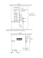
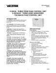
Issue 5 V-2003A-E - THREE ZONE CONTROL UNIT V-2003AHF-E - THREE ZONE TALKBACK CONTROL UNIT INTRODUCTION The V-2003A-E Three Zone control Unit provides telephone system access to multiple zones (up to 3) of one way paging plus all call. The V-2003AHF-E Three Zone Talkback Control Unit provides telephone system access to multiple zones (up to 3) of handsfree talkback and/or one-way paging with a one-way all call. "WARNING: To reduce the risk of fire or electric shock, do not expose this equipment to rain or moisture." SPECIFICATIONS Access Methods • • • "WARNING: Shock Hazard - Do Not Open." "AVIS: Risque de Choc Electrique ne pas Ouvrir." "PELIGRO: Corriente Electrica - No Abra." “CAUTION: To reduce the risk of fire replace only with same type 1A, 125V fuse. 1A, 125V may be replaced by a 0.5A, 250V provided voltage selector is set for 230V.” • Electronic Key System PABX (Loop or Earth Call Trunk) 600 Ohm page port equipped with separate contact closure and MF dialing capability (NOTE: Page port must be -directional if talkback paging is desired) Stand Alone Handset (used only for access of the V-2003A-E and V-2003AHF-E). Features of the V-2003A-E “DANGER: Afin de réduire le risque de feu, remplacez le fusible par le même type de fusible à 1A, 125V. On peut utiliser un fusible à 0.5A, 250V pourvu que le sélecteur ďalimentation soit fixé sur 230V. Ne pas ouvrir.” • • • • “VORSICHT: Zur verringerung von feuergefahr die sicherung nur mit derselben type 1A, 125V ersetzen. Statt 1A, 125V Kann 0.5A, 250V Benutzt werden, vorausgesetzt, die spannung ist auf 230V eingestellt. Nicht öffnen.” • “PELIGRO: Para reducir el peligro de incendio remplazarlo unicamente con un fusible del mismo tipo 1A, 125V. El fusible de 1A, 125V podra ser remplazado por uno de 0.5A, 250V si el selector de voltaje esta puesto en 230V. No abres.” • • • • • • • • • 1 3 zones of one-way paging One-way all call Integrated power supply Volume Controls supplied for * Background music * Page * Warble tone/single tone Dip switch programmable per zone (music and tones) Dial tone (optional) (#) Button returns dial tone Supplies 1 Amp at -24VDC for powering speaker amplifier assemblies Provides audio for up to 150 Valcom one-way speaker amplifier assemblies per zone 230VAC at 50Hz or 115VAC at 60Hz operation AC input fused at 0.5 Amp at 230VAC or 1 Amp at 115VAC Override capability Inhibit circuitry (speaker cancel) UL, CSA and VDE Listed 947205 Nominal Power Requirements Additional Features Supplied by the V-2003AHF-E • • • • • • Voltage: 115VAC 230VAC 3 zones of handsfree talkback, one-way or mixed paging. Dip switch programmable per zone (music, tones, and one-way or talkback). Pre-announce tone (optional). Repeated alert tone (optional). Two volume controls for handsfree paging * Page (phone to speaker) * Receive (speaker to phone) Supplies 0.5 Amp at 24VDC for powering one-way amplified speakers (a reduction of 0.5 Amps from the V-2003A-E). Current: 1 Amp 0.5 Amp NOTE: The V-2003A-E/V-2003AHF-E is equipped with a standard 3-prong MOLEX connector to allow connection of a battery backup supply in case of AC power failure. • • Priority Sequence The V-2003A-E and V-2003AHF-E are designed to allow a time clock signal to override an ongoing override page, override page to override system page, system page to override night ring or music and night ring to override music. Use a cord set consisting of a minimum 18 AWG cord and grounding type attachment plug rated a minimum of 15A, 250V. The cord set should have the appropriate safety approvals for the country in which the equipment will be installed and marked HAR. The socket outlet shall be installed near the equipment and shall be easily accessible. Environment Temperature: Humidity: 0 to 40°C 0 to 85% non-condensing OPERATION Physical Description DO NOT OPERATE UNIT WITH COVER REMOVED! Press the line key button (key system) or dial the appropriate loop or earth call trunk or page port access code (PABX) to access the control unit. Dial desired zone code: 1, 2, 3 or 5, 6, 7 for individual zones (1, 2 and 3 respectively); 4 or 8 for the all call. Ringback tone (if so optioned) will be heard in the telephone. Make announcement and hang up. Page automatically disconnects and background music (if programmed) returns. (Ringback tone, when optioned, provides an alert tone to the talkback zones on a V-2003AHF-E). The V-2003A-E and V-2003AHF-E are contained in single, gray steel cases which can be wall or shelf-mounted. • V-2003A-E: 7.15" H x 10" W x 3" D (18.16cm H x 25.40cm W x 7.62cm D) 4.1 lbs. (1.86 kg) • V-2003AHF-E: 7.15" H x 10" W x 3" D (18.16cm H x 25.40cm W x 7.62cm D) 5.6 lbs. (2.54 kg) Nominal Specifications Input Impedance: Input Level: Music Source Impedance: Music Input Level: Output Impedance: 600 Ohms -10dBm 8 to 600 Ohms -10 to -18dBm 8 Ohm (1 way) 45 Ohm (talkback) Output Level: -10dBm (1 way) 1 Watt (talkback) DC Output: -24VDC at 1 Amp (V-2003A-E) -24VDC at 0.5 Amp (V-2003AHF-E) Background Music Background music may be connected to the control unit. Background music will mute in the zone accessed for the duration of the page. Warble and Single Tones Warble tone is available over the P.A. system when a common audible contact closure or 90VAC ring voltage is supplied by the telephone system. A single tone is provided over the P.A. when the unit is activated by an additional contact closure. The single tone and warble tone may be dip switch selected on a per zone basis. (One dip switch is supplied per zone for tones, so single tone and warble tone are both selected on or both selected off). 2 Wiring Instructions for Loop or Earth Call Access INSTALLATION Precautionary Designations Plug 50 pin, female amphenol connector into J2 of the control unit and use a KRONE block for crossconnections (See Figure 2). CAUTION RISK OF ELECTRIC SHOCK DO NOT OPEN 1. CAUTION: To reduce the risk of electric shock, Do not remove cover. No user serviceable parts inside. Refer servicing to qualified service personnel. 2. This symbol indicates that dangerous voltage constituting a risk of electric shock is present within this unit. Make certain Battery Feed switch (SW2) is ON (in the Down position, see Figure 3). Ascertain SW1 is in proper position. SW1 should be in the UP position for loop start operation; SW1 should be in the DOWN position for earth call operation. NOTE: When using an earth call trunk port, an earth strap must be used to connect GND of the unit to an appropriate telephone system GND (see Figure 2). This symbol indicates that there are important operating and maintenance instructions in the literature accompanying this unit. NOTE: The telephone system referred to in this manual is the customer premise equipment such as a key system or PABX. The V-2003A-E/ V-2003AHF-E cannot be connected directly to the public telephone network (a central office line). All connections must be made prior to plugging the unit to AC power. Mounting The V-2003A-E/V-2003AHF-E was designed for wall or table mounting. Secure the unit to wall studs or suitable brace away from heat sources or strong magnetic fields (motors, fans, power supplies, etc.) with control and terminal strip accessible. Four wood screws are included for mounting. NOTE: All controls and terminations are accessed by removing the right side panel. Switch Selectable Options Loop or earth call access, are switch selectable on the V-2003A-E/V-2003AHF-E. SW1 selects the loop/ earth call option for system tip and ring. SW5 selects the loop/earth call option for override tip and ring. (See Figure 3 for location). A 12-position dip switch is provided for programming capabilities. Figure 3 indicates the function of each dip switch (i.e., the feature it activates). NOTE: For one-way paging on a V-2003A-E, the dipswitch for the talkback feature on a one-way zone must be set to "Off" (no zone x talkback). If a modular cord is used for Tip and Ring connections, connect (J1) RJ-11 A/Tip and B/Ring to the appropriate loop exchange port of the phone system. For punch down block A/Tip and B/Ring connections, connect Tip of the telephone system or loop or earth call trunk to the Tip (W/BL) pin and Ring to the (BL/W) of the KRONE block. Connection of One-Way Amplified Speakers Using twisted pair telephone wire, connect: Zone 1 Speaker A/Tip, B/Ring Zone 1 Speaker -24VDC Zone 1 Speaker GND Zone 2 Speaker A/Tip, B/Ring Zone 2 Speaker -24VDC Zone 2 Speaker GND Zone 3 Speaker A/Tip, B/Ring Zone 3 Speaker -24VDC Zone 3 Speaker GND - R/BL, BL/R - R/O - O/R - R/G, G/R - R/BR - BR/R - R/S, S/R - BK/BL - BL/BK NOTE: The V-2003A-E provides external power of 1 Amp of -24VDC to operate amplified speaker assemblies. Additional power supplies are required if more than one Amp is needed. Each speaker should be connected to only one power source. The V-2003A-E/V-2003AHF-E requires a power down reset in order to implement dipswitch changes. (Unplug AC power from the V-2003A-E/ V-2003AHF-E for a minimum of 30 seconds then reconnect to effect a dipswitch change). 3 The V-2003A-E/V-2003AHF-E may be used with one of the following: Connection of Talkback Speakers (V-2003AHF-E Only) Using twisted pair telephone wire, connect: • • • Zone 1 Speakers A/Tip, B/Ring - BK/G, G/BK Zone 2 Speakers A/Tip, B/Ring - BK/BR, BR/BK Zone 3 Speakers A/Tip, B/Ring - BK/S, S/BK NEMA 5-15 cord set for North American use CEE/7 cord set for Continental European use BS1363 cord set for United Kingdom use NOTE: Refer to Figure 4 for the voltage selector switch and fuse location. Make certain the voltage selector switch is placed at the appropriate rating and that the proper rated fuse is installed. NOTE: No more than two (2) 45 Ohm speakers should be connected to any talkback zone. Do not use 8 Ohm speakers. Page Port Access When used with page port access, the V-2003A-E/ V-2003AHF-E may only be used with a 600 Ohm page port that will pass MF tones for zone selection and that is equipped with a separate "page enable" contact closure. Additionally, the page port must be capable of passing bi-directional audio for talkback operation. Connect telephone system dry contact closure to O/W and W/O of connection block (see Figure 2). Power Connections Connect cord set to unit via IEC 320 female connector located on one end of cord set to IEC 320 male appliance coupler located on the V-2003A-E/V-2003AHF-E. For 115VAC use, verify fuse rating of 1 Amp and voltage selector switch displays 115V. For 230VAC use, verify fuse rating of 0.5 Amp and voltage selector switch displays 230V. After all required connections have been made, plug the cord set into appropriate AC wall outlet. NOTE: This equipment must be installed near an AC power outlet due to the power cord being used as a disconnect device. Telephone System Page Port KRONE Block Connections A/Tip W/BL B/Ring BL/W Battery Feed Switch (SW2) must be "OFF" Page Enable Contact Closure W/O O/W Page Port must: 1. Provide low level audio (Tip and Ring) and dry page enable contact closure. 2. Have capability to pass MF tones for zone selection. 3. Be bi-directional (pass audio in both directions) when with the V-2003AHF-E for handsfree talkback. FIGURE 1. PAGE PORT ACCESS 4 Optional Connections V-2003A-E Volume Adjustments There are two volume controls on the unit for individual adjustment of: • Background music • Tones (warble/single tone) A. Background Music Connections: Connect the low level (-10 to -18dBm, 8 to 600 Ohms) output of music source to (W/G) and (G/W) terminals of the cross connect block. Adjust music volume (page overrides music). Clockwise adjustment increases volume, counter clockwise decreases volume. During initial set up, adjust individual speaker volume controls for page first, then, adjust volume on page unit to the desired level for music and tones. NOTE: Failure to use a low level music source could cause music crosstalk on zones not receiving music. Connections for the V-2003AHF-E The V-2003AHF-E is programmable on a per zone basis for one-way or talkback communication. A single talkback zone may have both one-way and talkback speakers. One-way amplified speakers may be connected to the handsfree output of a zone programmed for talkback to augment the page output on that zone. (NOTE: Only talkback speakers are able to receive reply). V-2003AHF-E Volume Adjustments There are five additional volume controls on the V-2003AHF-E to control the volume of the handsfree talkback outputs. They are: • All Call (adjusts volume of page during all call on handsfree outputs). • Speaker to Phone (adjusts response volume from the speaker; should be turned as low as possible). • Phone to Speaker (adjusts volume of a page from phone) • Background Music (adjusts background music on handsfree outputs). • Tones (adjusts the volume of single and warble tones on handsfree outputs). Refer to Figure 4 for location of these controls. B. Time Clock Closure (Single Tone) Connections: Time clock contact closure - (V/G), (G/V) Time clock signaling will override page. C. UNA Closure (Warble Tone) Connections: Telephone System Night Answer (Contact Closure)(V/BR), (BR/V). This tone will override music but is overridden by a page. D. UNA Ringing (Warble Tone) Connections: 90VAC Night Answer Ringing- (V/S), (S/V) These connections will activate a night ring tone. E. Override Connections: Telephone System Page Override - (W/S),(S/W) Page override can be activated by a vacant loop exchange port, loop start or earth call trunk or dedicated single line phone. NOTE: Make certain SW1 is in correct position for loop or earth call mode of operation. TECHNICAL ASSISTANCE Assistance in troubleshooting is available from the factory. Call (540) 563-2000 and press 1 for Technical Support or visit our website at http://www.valcom.com. Should repairs be necessary, contact your local distributor for instructions. NOTE: One-Way Speakers may be connected to low level outputs on the V-2003AHF-E. 5 TABLE 1 - TROUBLESHOOTING CHART SYMPTOM SOLUTION 1. No output to speakers A. B. 2. No music output. 3. Programmed feature not functioning. A. Check for the presence of audio on the page outputs of the V-2003A-E/V-2003AHF-E during a page using a telephone test set. Refer to the Installation Section for connection information. Check AC line fuse on V-2003A-E/V-2003AHF-E. B. Using a telephone test set check for music on the music input terminals. Check program. A. B. Check program. Reprogram zone. VALCOM U.K. WARRANTY This product, bearing the "VALCOM" Trademark, excluding the batteries, is guaranteed by the manufacturer for the period of one year from the date of purchase and will, during this period, be repaired or replaced (with the same or a similar model), at our option, free of charges, if there is any defect due to faulty materials or workmanship. This guarantee does not cover defects arising from accidental damage, misuse or wear and tear, and is available only to the original purchaser of the product from an official "VALCOM" distributor or dealer. This guarantee applies to all Valcom products purchased and used in the EEC. Products should be returned to your nearest Valcom distributor or dealer. If, however, the product has not been purchased in the EEC country where the distributor or dealer is located, the customer may be advised to return to the EEC country where the purchased originated, if parts are unavailable or there are other unavoidable circumstances which hinder, or prevent service being given under guarantee. Any person claiming under this guarantee must, on returning the product, supply proof of the date of purchase and a brief description of the nature of the fault. NOTE: PROOF OF PURCHASE WILL BE ACCEPTED IN THE FORM OF EITHER THE ORIGINAL RECEIPT OF PURCHASE OR THE GUARANTEE CERTIFICATE AND SUCH RECEIPT OR CERTIFICATE MUST BEAR THE DISTRIBUTOR OR DEALERS OFFICIAL STAMP AND THE DATE OF PURCHASE. Charges will be made for all repairs unless either the purchase receipt or the stamped and dated Guarantee Certificate is returned with the product. The guarantee does not effect the Statutory Rights of the customer. 6 V-2003A-E or V-2003AHF-E J1 25 Pair KRONE Connection Block R/G O/R R/O BL/R R/BL S/W To Loop or Earth Call Trunk Override W/S BR/W W/BR Low Level Music Source G/W W/G O/W W/O BL/W W/BL 8 7 6 5 4 3 2 1 Y/S GND OUT BR/Y -24V OUT Y/BR ZONE 2 B/RING G/Y ZONE 2 A/TIP Y/G GND OUT O/Y -24V OUT Y/O ZONE 1 B/RING BL/Y ZONE 1 A/TIP Y/BL OVERRIDE B/RING S/BK OVERRIDE A/TIP BK/S INHIBIT BR/BK UNUSED BK/BR MUSIC G/BK MUSIC BK/G PAGE PORT CC O/BK PAGE PORT CC BK/O B/RING BL/BK A/TIP BK/BL 9 9 8 8 7 7 6 6 5 4 3 2 1 ZONE 3 B/RING ZONE 3 A/TIP ZONE 2 B/RING ZONE 2 A/TIP ZONE 1 B/RING ZONE 1 A/TIP NOT USED S/V V/S BR/V V/BR G/V V/G O/V NOT USED V/O +GND OUT BL/V -24V OUT V/BL 5 4 3 2 1 90VAC Ringing from an Assigned Station Port Telephone System Common Audible UNA CLOSURE X Contact Closure UNA RINGING SINGLE TONE X Time Clock Contact NOT USED Valcom One-Way Amplified Speakers G/R ZONE 3 A/TIP HANDSFREE OUTPUTS R/BR 9 B/Y NOT USED BR/R 0 R/S ZONE 3 B/RING 0 S/R 0 Ground Strap required for Earth Calling Access Loop or Telephone Earth Calling System Trunk Contact Closure (Page Port) FIGURE 2 - CONNECTIONS FOR THE V-2003A-E AND THE V-2003AHF-E 7 Figure 3 Dip Switches for both units and Volume Controls for the V-2003A-E SW2 J1 Battery Feed OFF Battery Feed ON RJ11 SW1 System A/Tip-B/Ring Override A/Tip-B/Ring SW5 Loop Start Earth Call Loop Start Earth Call Zone 3 Music Zone 3 Tones Zone 3 Talkback Zone 2 Music Zone 2 Tones Zone 2 Talkback Zone 1 Music Zone 1 Tones Zone 1 Talkback No System Dial Tone* No System Alrt/Rngbk Tone* No System Repeated Alert* SW3 SW3 - DIPSWITCHES Switch Down is "ON" Position and selects option as listed Dip Switches Switch Up (OFF) Switch pressed Down (ON) R34 TONES R6 MUSIC J2 Male Amphenol Connector * Repeated system alert tone is available only with the V-2003AHF-E. Ringback tone provides alert tone over speakers on handsfree outputs with the V-2003AHF-E. Figure 4 Enclosure Orientation and Volume Controls for the V-2003AHF-E Spkr/ Phone Phone/ Spkr Fuse 1A @ 125V-or .5A @ 230V Page V-2003AHF-E Tones Music Amphenol Connector Voltage Selector Switch IEC 320 Appliance Coupler 8 Volume Controls