1
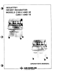
INTEGRUS
Installation and User Instructions
en
Integrus
Language Distribution
System
LBB 3222/04
6-Channel Interpreter
Desk with Loudspeaker
LBB 3422/20 Integrus
Audio Input and
Interpreters Module
INTEGRUS | Installation and User Instructions | Safeguards
Important Safeguards
Prior to installing or operating this product always
read the Safety Instructions which are available as
a separate document.
Bosch Security Systems | 2005-04 | 9922 141 70164en
INTEGRUS | Installation and User Instructions | Table of contents
Table of contents
1
6-Channel interpreter desk with loudspeaker (LBB 3222/04) . . . . . . . . . . . . . . . . . . . . . . . . . . . . . . . . . .1
1.1
Introduction . . . . . . . . . . . . . . . . . . . . . . . . . . . . . . . . . . . . . . . . . . . . . . . . . . . . . . . . . . . . . . . . . . . . . .1
1.2
Front panel controls . . . . . . . . . . . . . . . . . . . . . . . . . . . . . . . . . . . . . . . . . . . . . . . . . . . . . . . . . . . . . . . .1
1.3
Rear panel controls . . . . . . . . . . . . . . . . . . . . . . . . . . . . . . . . . . . . . . . . . . . . . . . . . . . . . . . . . . . . . . . . .3
1.4
Interpretation procedures . . . . . . . . . . . . . . . . . . . . . . . . . . . . . . . . . . . . . . . . . . . . . . . . . . . . . . . . . . . .3
1.5
Configuring the interpreter’s system . . . . . . . . . . . . . . . . . . . . . . . . . . . . . . . . . . . . . . . . . . . . . . . . . . . .4
1.6
Auto floor function . . . . . . . . . . . . . . . . . . . . . . . . . . . . . . . . . . . . . . . . . . . . . . . . . . . . . . . . . . . . . . . . .5
2
Integrus audio input and interpreters module (LBB 3422/20) . . . . . . . . . . . . . . . . . . . . . . . . . . . . . . . . . .6
2.1
Introduction . . . . . . . . . . . . . . . . . . . . . . . . . . . . . . . . . . . . . . . . . . . . . . . . . . . . . . . . . . . . . . . . . . . . . .6
2.2
Configuration . . . . . . . . . . . . . . . . . . . . . . . . . . . . . . . . . . . . . . . . . . . . . . . . . . . . . . . . . . . . . . . . . . . . .7
3
Connecting to an Integrus transmitter . . . . . . . . . . . . . . . . . . . . . . . . . . . . . . . . . . . . . . . . . . . . . . . . . . . . .8
3.1
Connecting interpreters desks LBB 3222/04 directly . . . . . . . . . . . . . . . . . . . . . . . . . . . . . . . . . . . . . .8
3.1.1 Maximum cable length for connecting interpreters desks LBB 3222/04 . . . . . . . . . . . . . . . . . .9
3.1.2 Recording the audio channels . . . . . . . . . . . . . . . . . . . . . . . . . . . . . . . . . . . . . . . . . . . . . . . . . .10
3.2
Connecting interpreters desks LBB 3222/04 via the CCS 400 system . . . . . . . . . . . . . . . . . . . . . . . .11
3.3
Connecting other analogue conference systems . . . . . . . . . . . . . . . . . . . . . . . . . . . . . . . . . . . . . . . . . .11
4
Technical data . . . . . . . . . . . . . . . . . . . . . . . . . . . . . . . . . . . . . . . . . . . . . . . . . . . . . . . . . . . . . . . . . . . . . . . . .12
4.1
LBB 3222/04 6-Channel interpreter desk with loudspeaker . . . . . . . . . . . . . . . . . . . . . . . . . . . . . . . .12
4.1.1 Physical characteristics . . . . . . . . . . . . . . . . . . . . . . . . . . . . . . . . . . . . . . . . . . . . . . . . . . . . . . . .12
4.1.2 Electrical characteristics . . . . . . . . . . . . . . . . . . . . . . . . . . . . . . . . . . . . . . . . . . . . . . . . . . . . . . .12
4.2
LBB 3422/20 Integrus audio input and interpreters module . . . . . . . . . . . . . . . . . . . . . . . . . . . . . . . .12
4.2.1 Physical characteristics . . . . . . . . . . . . . . . . . . . . . . . . . . . . . . . . . . . . . . . . . . . . . . . . . . . . . . . .12
4.2.2 Electrical characteristics . . . . . . . . . . . . . . . . . . . . . . . . . . . . . . . . . . . . . . . . . . . . . . . . . . . . . . .12
4.3
Connection details . . . . . . . . . . . . . . . . . . . . . . . . . . . . . . . . . . . . . . . . . . . . . . . . . . . . . . . . . . . . . . . . .13
Bosch Security Systems | 2005-04 | 9922 141 70164en
INTEGRUS | Installation and User Instructions
Bosch Security Systems | 2005-04 | 9922 141 70164en
INTEGRUS | Installation and User Instructions | 6-Channel interpreter desk with loudspeaker
1
6-Channel interpreter desk
with loudspeaker
(LBB 3222/04)
en | 1
Note: Flashing indicators warn that the
language channel occupied by this desk
is also being used by one or more other
desks.
1.1
Introduction
The LBB 3222/04 6-channel interpreter desk provides
listening and speaking facilities for interpreters using
the CCS 800, CCS 400 or non-BOSCH discussion
systems. Up to 12 desks can be connected to an
Integrus transmitter using the Integrus audio input and
interpreters module (LBB 3422/20). It can distribute
up to 6 outgoing languages. An ‘auto-floor’-feature is
incorporated for relay interpretation. This allows a less
well-known floor language to be translated by one
interpreter into a language familiar to all other interpreters and relayed as the auto-floor.
The LBB 3222/04 has an integral loudspeaker and is
supplied with a microphone incorporating an illuminated status ring to warn everyone in the booth that the
microphone is active. Two outgoing channels are provided, A and B, switchable by means of a channel
select key.
Figure 1.1
LBB 3222/04 6-channel interpreter desk
Bosch Security Systems | 2005-04 | 9922 141 70164en
1.2 Front panel controls
The desk has the following front-panel controls and
indicators (see figure 1.1):
Figure 1.1:
1. Microphone activating key - 2-position toggle
switch for activating the microphone. An interlock
facility can be enabled (using the under-panel controls) that prevents the microphone being activated
if the desk’s outgoing language distribution channel
is occupied by another desk.
2. Microphone status indicators - Two red LEDs to
indicate that the microphone is active.
3. Microphone mute key - A non-locking push-button to temporarily mute the microphone. When
pressed, the status indicators and status ring are
‘off’, but the outgoing language distribution channel
remains occupied by the desk.
4. Microphone - Gooseneck microphone with integral status indicator ring.
INTEGRUS | Installation and User Instructions | 6-Channel interpreter desk with loudspeaker
5. Call-channel key - Non-locking push-button to
route the microphone to the call channel for oneway communication with the operator (with priority
over the A/B channel). The microphone status indicators and status ring are ‘on’ when the call-channel
key is pressed. The outgoing language distribution
channel remains occupied by the desk. Not applicable for use with CCS 800 discussion systems.
6. Outgoing message key - Non-locking push-button
to be used for signalling purposes. When pressed,
contacts are closed. This switch is connected to the
6-pole DIN connector for custom wiring.
7. Incoming message indicator - A yellow LED with
1 k W series resistor connected to the 6-pole DIN
connector. To be used for custom signalling purposes.
8. Tone/volume controls - Rotary volume, bass and
treble controls for the headphone.
9. Volume control - Rotary volume control for builtin loudspeaker.
10. Monitor loudspeaker - Built-in loudspeaker for
monitoring without headphones. The speaker is
only active when the microphone is off.
11. Incoming channel selector - 8-position rotary
switch to select either OR, OR2 or channels 1 to 6
for monitoring as incoming language. This switch is
only active if the incoming channel pre-selector key
is in the ‘up’-position.
Note: For a full explanation of terms
OR and OR2, see section 1.6.
12. Incoming channel pre-selector key - 2-position
toggle switch to select either OR when in the
‘down’-position, or the channel selected by the
incoming channel selector knob when in the ‘up’position. If OR is selected and OR2 is activated
using the auto-floor-feature, the desk automatically
receives OR2 for monitoring.
13. Incoming channel OR2 indicator - Green LED to
indicate that OR2 is active instead of OR during
relay interpretation.
Bosch Security Systems | 2005-04 | 9922 141 70164en
en | 2
14. A-B channel selector key - 2-position toggle
switch for selecting either A or B. If use of channel
B is inhibited, the outgoing channel will be the one
pre-set for the desk by the under-panel A select
control. If channel B is enabled, the outgoing channel can be selected with the channel-B select keys.
15. Outgoing channel-A indicators - 6 green LEDs to
indicate which outgoing channel is assigned to the
desk for channel A using the under-panel controls.
16. Outgoing channel-B indicators - 6 green LEDs to
indicate which outgoing channel is assigned to the
desk for channel B using the outgoing channel-B
select keys.
17. Outgoing channel-B select keys - 6-way interlocking push-button array to select the outgoing channel
when channel B is selected.
18. A-B channel select indicators - 2 red LEDs to
indicate which channel, A or B, is selected.
19. Outgoing OR2 indicator - Green LED to indicate
that the desk is enabled for relaying OR2 to other
desks (using under-panel controls).
20. Engaged channel indicators - 2 yellow LEDs, one
each for A and B, to indicate that the outgoing
channel selected is occupied by one or more desks.
A flashing LED indicates that the outgoing channel
occupied by the desk is also being used by one or
more other desks.
INTEGRUS | Installation and User Instructions | 6-Channel interpreter desk with loudspeaker
en | 3
1.3 Rear panel controls
1.4 Interpretation procedures
The rear panel of the interpreter desk contains the following controls and connectors (see figure 1.2).
The original floor language spoken by a delegate is distributed throughout the conference area, either via a
PA system, or via built-in loudspeaker units on the delegates microphone units (both methods may also be
used simultaneously).
This floor language is also distributed to all interpreters
desks, where through their headphone sets the interpreters can listen to the floor language to base their
interpretations.
Figure 1.2
Rear view of LBB 3222/04
Figure 1.2:
1. Headset switch - 2-position slide switch to select
either the headset’s microphone or the built-in
gooseneck microphone.
2. System cable - 3 m long cable terminated with a
25-pole male D-type connector for connecting the
desk to the preceding desk or to the central.
3. System connector - 25-pole female D-type connector (lockable) for connecting to the next desk.
4. Headphone connector - 6.3 mm jack socket for
connecting the headphone.
5. Headset connector - 5-pole female 180° DIN connector for connecting a headset (in accordance with
IEC 268-1 1).
6. Message connector - 6-pole female DIN connector
for message function (if required).
Bosch Security Systems | 2005-04 | 9922 141 70164en
The 6-channel interpretation system is operated completely independently from the system operator, and is
operated as a stand-alone system only.
The procedures used for interpreting the original floor
language is understood by all interpreters, and where
the floor language is not so well known, two different
operational procedures can be used: normal operational mode and relay interpretation mode.
• In the normal operational mode, where the original
floor language is familiar to all interpreters, the
interpreters will listen via their headphone or headset to the original floor language. The translations
are then fed to the appropriate channels on the delegate’s program selector units or receivers.
• In a situation where interpreters are unfamiliar with
the floor language (and therefore unable to translate
it), the CCS 800 system has a relay interpretation
facility. This facility allows for an interpreter who is
familiar with the floor language to relay his translation to other interpreters to which they can base
their own translations.
INTEGRUS | Installation and User Instructions | 6-Channel interpreter desk with loudspeaker
1.5 Configuring the interpreter’s
system
Set-up selector DIL switch 2
Switch
The configuration of the 6-channel interpreter’s system
is carried out independently of the CCS 800 system.
The controls located under the removable panel on the
desk must be pre-set before putting the system into
operation. To gain access to the controls, remove the
plastic protection cover and text plate located at the
top of the unit. This is achieved by inserting a small
pointed implement into the holes at either side of the
cover and carefully pushing forward to lever it off (see
figure 1.3).
On
Off
Channel B disable
Channel B enable
2
Mic. OR2 disable
Mic. OR2 enable
3
Interlock enable
Interlock disable
4
Slave
Master
5
Loudspeaker
Loudspeaker
OR2 disable
OR2 enable
1
6, 7, 8
Figure 1.4
SW 2-1
SW 2-2
Figure 1.3
Under-panel controls on the
LBB 3222/04 interpreter desk
A-select switch
The outgoing language distribution channel assigned to
each desk must be pre-set using the A-select 6-position
rotary switch. Each booth should be assigned a different channel (1 to 6). The language assigned to each
channel can be written on the removable panel in the
spaces provided alongside the outgoing channel A indicators. The appropriate LED will illuminate to indicate
which language is assigned to a particular desk. Factory
setting: channel 1.
Bosch Security Systems | 2005-04 | 9922 141 70164en
en | 4
SW 2-3
SW 2-4
Not used
Factory setting of DIL switch 2
B-enable - If desks are not to make use of
the B output, the B-enable switch must be
switched ‘on’. The outgoing language distribution channel for each desk will then be
determined by the A-select switch only
(regardless of the position of the A-B channel
selector key on the front panel).
OR2 enable - To configure an auto-floor
system, the desk from which the transfer
interpretation will be made must have the
OR2 function enabled. The outgoing channel OR2 indicator will illuminate on this
desk. The B-enable switch must be ‘off’ for
this desk.
Interlock - To prevent two or more desks
using the same outgoing channel, the interlock feature can be enabled. When this
switch is ‘on’, the microphone will remain
inactive if an occupied outgoing channel is
selected.
Master / slave - If more than one desk is
installed in a booth, the additional desks
must be set with this switch in the ‘on’-position. The first desk in a booth (that nearest
to the IR transmitter) must have this switch
in the ‘off’-position. If only one desk is
installed in the booth, this switch must also
be ‘off’.
INTEGRUS | Installation and User Instructions | 6-Channel interpreter desk with loudspeaker
SW 2-5
OR-only - When the OR-only switch is in
the ‘on’-position, the loudspeaker will always
monitor the floor channel. When the ORonly switch is in the ‘off’-position, the loudspeaker will automatically switch over to the
OR2 channel when this channel is available.
1.6 Auto floor function
To cater for circumstances where the original floor language is either well known or less well known, two different operational procedures can be utilised.
Figure 1.5
Figure 1.6
Normal operation (OR1 active)
Relay interpretation using the auto-floor feature
(OR2 active)
Bosch Security Systems | 2005-04 | 9922 141 70164en
en | 5
In the normal operational mode (shown in figure 1.5),
where the original floor language (OR) is familiar to all
interpreters, they will listen to the original floor language for interpretation. The translations are then fed
to the appropriate language distribution channels.
In a situation where interpreters are unfamiliar with
the floor language and therefore unable to interpret it,
the system offers an automated relay interpretation
facility (‘auto floor’ - see figure 1.6).
An interpreter assigned to translate the floor language,
translates it into another language easily understood by
other interpreters.
The floor language (OR) on all interpreters’ desks will
be replaced by this transfer interpretation. This transfer
interpretation or ‘auto floor’ (OR2) is then used as a
base for further translations.
In the example in figure 1.6, Japanese is the OR and
the auto-floor facility is enabled on the Japanese interpreter desk using the set-up selector DIL switch under
the removable panel (the outgoing OR2 indicator is
illuminated on this desk). This interpreter selects outgoing channel B and automatically relays a French translation as OR2 to all other desks for interpretation and
also feeds the French language distribution channel.
The incoming channel OR2 indicator shows on all
other desks that auto floor is active.
INTEGRUS | Installation and User Instructions | Integrus audio input and interpreters module
2
Integrus audio input
and interpreters module
(LBB 3422/20)
2.1 Introduction
An Integrus audio input and interpreters module is
required when an Integrus transmitter is to be used for
direct connection of interpreters desks LBB 3222/04
(in combination with e.g. the CCS 800 system) or with
analogue conference systems (such as the CCS 400).
The interface module must be mounted in the transmitter housing.
4
1
Figure 2.1
5
2
4
3
1
Integrus audio input and interpreters
module, rear view and PCB layout
Figure 2.1:
1. Interface connector – A 25-pole sub-D female
connector for direct connection of up to 12 LBB
3222/04 interpreters desks or analogue conference
systems with interpretation.
2. Positions for input transformers – Eight input
transformers can be mounted for galvanic separation of source and electronics inputs. The eight
Integrus audio inputs at the 25-pole D-type plug
can be isolated by adding eight audio transformers
(Beyer type TR/BV3) in these positions.
3. Function switches – Three DIL switches for determining module functionality.
4. PCB connector - A 55-pins connector that connects the module to the Integrus transmitter’s main
PCB.
5. Mounting plate.
Bosch Security Systems | 2005-04 | 9922 141 70164en
en | 6
INTEGRUS | Installation and User Instructions | Integrus audio input and interpreters module
2.2
en | 7
Configuration
Notes:
Before using the Integrus audio input and interpreters
module, the operation mode must be chosen by setting
the DIL function switches on the module’s circuit
board:
• Select the mode in which the module must operate:
1. As an interface to one or more LBB 3222/04
interpreters desks.
2. As an interface to other audio sources.
• Select if floor distribution (see section 1.6) should
be enabled.
1. Enable floor distribution when LBB 3222/04
interpreters desks are directly connected
2. Disable floor distribution when LBB 3222/04
interpreters desks are connected via a CCS 400
system.
• Select the channels on which the module’s signals
will be distributed.
•
If floor distribution is enabled (DIL
switch III-4 off), the floor audio signal
will be distributed on those channels
where the interpretation microphone is
switched off.
•
When interfacing between more than
one LBB 3222/04 interpreter desk and
the infra-red system, or interfacing
between the CCS 400 power supply
and the infra-red system, the floor
distribution should be disabled
(DIL switch III-4 on).
•
Do not use a CCS 400 power supply in
combination with direct connection to
LBB 3222/04 interpreter desks, as this
will cause a fuse to blow.
•
When the Integrus audio input and
interpreters module is used in
The table below lists all the settings.
combination with audio signals
connected to the cinch inputs of the
Integrus transmitter, the signals on
corresponding channels are mixed.
•
Check the positions of the
DIL-switches before mounting the
LBB 3422/20 Integrus audio input
and interpreters module in an
Integrus transmitter.
DIL
Switch
Function
On
Off
I
1,2,3,4,5,6,7,8
Interpretation
Direct connection to
Connection to
LBB 3222/04 interpreters desks
other audio sources
II
1,2,3,4,5,6,7,8
Interpretation
Direct connection to
Connection to
LBB 3222/04 interpreters desks
other audio sources
III
1,2,3
Interpretation
Direct connection to
Connection to
LBB 3222/04 interpreters desks
other audio sources
Floor distribution
Disabled
Enabled
Channels 8-15
Channels 0-7
III
4
III
5
Channel selection
III
6,7,8
Not used
Bosch Security Systems | 2005-04 | 9922 141 70164en
INTEGRUS | Installation and User Instructions | Connecting to an Integrus transmitter
3
Connecting to an Integrus
transmitter
Note: To connect the floor signal, a cable
with a male XLR connector and a male
cinch connector must be made. See
3.1 Connecting interpreters desks
LBB 3222/04 directly
An Integrus transmitter requires the LBB 3422/20
Integrus audio input and interpreters module to directly interface with one or more LBB 3222/04
interpreter desks. This module must be mounted in
the transmitter housing (see the Integrus installation
manual).
Up to 12 interpreter desks can be loop-through connected to the module. The system cable of the first
interpreter desk is connected to the 25-pole sub-D
connector on the Integrus audio input and interpreters
module. The system cables of the next desks are loopthrough connected to the system input plugs on the
preceding desks.
The floor signal for the interpreters desk is connected
to the Aux-Left input of the Integrus transmitter with
an XLR connector. The floor signal can come from a
CCS 800 analogue conference system (i.e. the line output cinch connector, see the CCS 800 installation manual) or from an external audio source, such as an audio
mixer.
en | 8
figure 3.1 and figure 3.2 for the wiring.
Figure 3.1
Connecting one or more LBB 3222/04
interpreter desks directly to the modular
IR transmitter
The DIL switches on the Integrus audio input and
interpreters module must be set to ‘Direct connection
to LBB 3222/04 interpreter desks’ (see section 2.2).
The ‘Aux. Input’ mode of the Integrus transmitter must
be set to ‘Emergency/Mono’ (see the Integrus installation manual).
XL
Integrus
AUX-Left
Figure 3.2
1
2
3
Wiring of the cinch to XLR connecting cable
Bosch Security Systems | 2005-04 | 9922 141 70164en
CCS800
Line output
INTEGRUS | Installation and User Instructions | Connecting to an Integrus transmitter
en | 9
3.1.1 Maximum cable length for connecting
interpreters desks LBB 3222/04
The maximum length of the cables to connect the
interpreters desks to the Integrus transmitter depends
on the number of interpreters desks. A leader cable
connects the first interpreters desk to the transmitter.
An extension cable may be needed between the interpreters desks. The table below shows the maximum
extension cable length (additional to the standard 3 m
cable) that can be used with different numbers of interpreters desks.
Number of interpreters desks LBB 3222/04
Additional leader cable length between
2
4
6
8
10
12
meter
100
50
35
15
5
0
meter
34
8
2.9
2.4
1.8
1
2
4
6
8
10
12
feet
328
164
115
49
16
0
feet
112
26
9.5
7.9
6.0
3.3
first interpreter desk and transmitter
Additional extension cable lengths
between interpreters desks
Number of interpreters desks LBB 3222/04
Additional leader cable length between
first interpreter desk and transmitter
Additional extension cable lengths
between interpreters desks
Bosch Security Systems | 2005-04 | 9922 141 70164en
INTEGRUS | Installation and User Instructions | Connecting to an Integrus transmitter
3.1.2
en | 10
Recording the audio channels
To record the audio channels, a connection box can be
inserted between the interpreters desks LBB 3222/04
and the Integrus audio input and interpreters module
LBB 3422/20. Such a connection box should be locally made. See figure 3.3 for the wiring.
Channel 6
Channel 5
Channel 4
Channel 3
Channel 2
Channel 1
Floor
RECORDING EQUIPMENT
14 x
LBB 3422/20
Audio 1 input
Audio 2 input
Audio 3 input
Audio 4 input
Audio 5 input
Audio 6 input
Audio 7 input
Audio 8 input
Audio Comm
Audio AF
Supply (+12V)
Supply (- 12V)
Earth
Figure 3.3
LBB 3222/04
1
14
4
18
2
16
5
17
7
19
8
22
6
20
11
23
9
21
3
15
24
25
12
13
10
Connection box for recording audio and language channels
Bosch Security Systems | 2005-04 | 9922 141 70164en
1
14
4
18
2
16
5
17
7
19
8
22
6
20
11
23
9
21
3
15
24
25
12
13
10
OR Floor Channel
Channel 1
Channel 2
Channel 3
Channel 4
Channel 5
Channel 6
Busy in
Comm.
OR2 Auto Relay
Supply (+27V)
Ground
Earth
INTEGRUS | Installation and User Instructions | Connecting to an Integrus transmitter
3.2 Connecting interpreters desks
LBB 3222/04 via the CCS 400
system
An Integrus transmitter requires the LBB 3422/20
Integrus audio input and interpreters module to
interface with the CCS 400 discussion and interpretation system. This module must be mounted in
the transmitter housing (see the Integrus installation
manual).
The CCS 400 system is connected to the Integrus
audio input and interpreters module by means of a 25pole sub-D connecting cable. The interpreters desks
and the floor signal are connected to the CCS 400
system. See the CCS 400 installation manual for
more information.
en | 11
3.3 Connecting other analogue
conference systems
An Integrus transmitter requires the LBB 3422/20
Integrus audio input and interpreters module to
interface with other analogue conference systems.
This module must be mounted in the transmitter
housing (see the Integrus installation manual).
The analogue conference systems are connected directly to the Integrus audio input and interpreters module
by means of a 25-pole sub-D connecting cable. For
pinning information see chapter 4.
It is also possible to connect a conference system
directly to the Integrus audio cinch inputs of an
Integrus transmitter. In that case the interface module
is not necessary.
Note: Before connecting the CCS 400
Notes:
analogue conference systems, the DIL
•
Before connecting other analogue
switches on the Integrus audio input and
conference systems, the DIL switches
interpreters module must be set to
on the Integrus audio input and inter-
‘Connection to other audio sources’.
preters module must be set to
For details of the required settings, see
‘Connection to other audio sources’.
section 2.2.
For details of the required settings,
see section 2.2.
•
If galvanic separation is required,
add Beyer type TR/BV3 audio
transformers on the module’s PCB
(see section 2.1).
Bosch Security Systems | 2005-04 | 9922 141 70164en
INTEGRUS | Installation and User Instructions | Technical data
4
Technical data
4.1 LBB 3222/04 6-Channel interpreter desk with loudspeaker
4.2 LBB 3422/20 Integrus audio
input and interpreters module
4.2.1 Physical characteristics
Mounting
4.1.1 Physical characteristics
Mounting
Table top or flush mounting
(0.79–2.28 x 9.84 x 7.44 inch)
1.75 kg (3.85 lb)
Finish
Light gray
Dimensions (H x W x D)
Weight
to +3.5 dBV (1500 mVeff)
Audio input level without AGC
-4.4 dBV (600 mVeff)
(-2 dB)
Asymmetric input impedance
≥ 10 kOhm
< 32 dB
DC input impedance
≥ 200 kOhm
< 5%
at overload
Cross talk attenuation
-16.5 dBV (150 mVeff)
125 Hz (-10 dB) to 12.5 kHz
pressure due to inherent noise
Total harmonic distortion
188 g (0.41 lb)
4.2.2 Electrical characteristics
Audio input level with AGC
Rated equivalent sound
100 x 45 x 231 mm
(39 x 21 x 91 inch)
4.1.2 Electrical characteristics
Frequency response
Mounting plate and two screws
included
Dimensions (Hfront x Hrear x W x D) 20-58 x 250 x 189 mm
Weight
en | 12
> 66 dB
Bosch Security Systems | 2005-04 | 9922 141 70164en
INTEGRUS | Installation and User Instructions | Technical data
4.3 Connection details
System cable
en | 13
Headphone
6.3 mm jack socket
connector
Contact
Function
A 3 m long cable terminated with a 25-pole
Tip
Audio out
male D-type connector
Fling
Audio out
Pin nr.
Function
Sleeve
Return
1, 14
Floor line (OR)
2, 16
Outgoing language distribution
Headset
5-pole female 180° DIN connector in
channel 2
connector
accordance with IEC 268-11
3, 15
Auto floor (OR2)
Pin nr.
4, 18
Outgoing language distribution
1
Mic. live
channel 1
2
Mic. return
Outgoing language distribution
3
Left-hand headphone
channel 3
4
Return both headphones
Outgoing language distribution
5
Right-hand headphone
5, 17
6, 20
Function
channel 6
7, 19
Outgoing language distribution
Message
6-pole female DIN connector
channel 4
connector
Pin nr.
Function
8, 22
Outgoing language distribution
1
Connected to outgoing
9, 21
Call channel
2
-
10
Ground reference
3
Connected to outgoing
12, 13
Supply ground
23
Status line
4
Connected via internal series
24, 25
Positive supply voltage
channel 5
message key
message key
resistor to incoming message
indicator LED (anode)
System
25-pole female D-type connector
connector
Pin nr.
Function
message indicator LED
1, 14
Floor line (OR)
(cathode)
2, 16
Outgoing language distribution
3, 15
Auto floor (OR2)
4, 18
Outgoing language distribution
`
channel 2
channel 1
5, 17
Outgoing language distribution
6, 20
Outgoing language distribution
7, 19
Outgoing language distribution
8, 22
Outgoing language distribution
channel 3
channel 6
channel 4
channel 5
9, 21
Call channel
10
Ground reference
12, 13
Supply ground
23
Status line
24, 25
Positive supply voltage
Bosch Security Systems | 2005-04 | 9922 141 70164en
5
Connected to incoming
INTEGRUS | Installation and User Instructions
Product index
Products
LBB 3222/04
LBB 3422/20
6-channel interpreter desk with loudspeaker . . . . . . . . . . . . . . . . . . . . . . . . . . . . . . . . . . . . . .1
audio input and interpreters module . . . . . . . . . . . . . . . . . . . . . . . . . . . . . . . . . . . . . . . . . . . .6
Bosch Security Systems | 2005-04 | 9922 141 70164en
INTEGRUS | Installation and User Instructions
Bosch Security Systems | 2005-04 | 9922 141 70164en
For more information please visit www.boschsecuritysystems.com
© 2005 Bosch Security Systems B.V.
Data subject to change without notice
2005-04 | 9922 141 70164en