1
US 20080089519A1
(19) United States
(12) Patent Application Publication (10) Pub. No.: US 2008/0089519 A1
Ekberg
(43) Pub. Date:
Apr. 17, 2008
(54)
SECURE KEY EXCHANGE ALGORITHM
FOR WIRELESS PROTOCOLS
(75) Inventor:
Publication Classi?cation
(51)
Jan-Erik Ekberg, Vantaa (Fl)
(52)
Correspondence Address:
Int. Cl.
H04L 9/00
H04K 1/00
US. Cl. ......................... .. 380/270; 380/44; 380/274
(57)
ABSTRACT
MORGAN & FINNEGAN, L.L.P.
_
3 WORLD FINANCIAL CENTER
NEW YORK NY 10281_2101
(73)
(21)
_
Appl' NO"
_
_
_
A system for establishing encryption keys in a manner
suitable for linking loW complexity and/or poWer con
’
_
Asslgneer
(2006.01)
(2006.01)
strained Wireless devices. The present invention uses a
combination of encryption algorithms and events, possibly
including user manual intervention, to create a randomized
encryption key that is substantially more di?icult for a third
NOKIA CORPORATION, ESPOO
(Fl)
party device to decipher than present automated algorithms
(22) Filed:
11/548’812
currently in use. A user may randomly trigger, through a key
press, information to be sent from a sending device to a
receiving device Which is used to establish an encryption
Oct. 12, 2006
key.
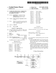
500
504
\
\\
SESSION KEY INFORMATION
DEVICE A
>
502
/
DEBVTIgEIgS)
U
500
505
\\
502
\\
DEVICE A
<
500
KEYS MATCHED FROM POOL OF KEYS
510
\
/
508
>
DEVICE B
512
502
\
?/
DEVICE A
DEVICE C
KEYS MATCHED FROM
REDUCED POOL OF KEYS
DEVICE B
KEYS MATCHED FROM
REDUCED POOL OF KEYS
514
500
\
\\
DEVICE A
|
COMPUTED KEY INFORMATION
502
>
DEVICE B
I
DERIVED)
(KEY
DERIVED)
(KEY
<
COMPUTED KEY INFORMATION
516
/
I
I
Patent Application Publication
Apr. 17, 2008 Sheet 1 0f 12
MUZSm-FOI
QU>
401F2 m0oz26 k
o:
o2.
our
.vnw
US 2008/0089519 A1
Patent Application Publication
Apr. 17, 2008 Sheet 3 0f 12
US 2008/0089519 Al
.QEN
#NN
mum
wNN
onu
..
6.$21“5E:
I
O
C
Q
>>$521
I
I
Q
I
I
I
I
a
I
n
a
n
n
o
0
n
?xuOo-wim
0
SN5
tIncl-ru.
MW
(6...
.wow
vGd3:2:8
Patent Application Publication
cm:
4M.97
US 2008/0089519 A1
Patent Application Publication
Apr. 17, 2008 Sheet 5 0f 12
US 2008/0089519 A1
onN
MM.07
I.918653
?w£m0c:2o?3u->.5m £2$856s3.mw NamccNQNN
NNNNON
Patent Application Publication
4m.0:
Apr. 17, 2008 Sheet 7 0f 12
Now
@moSn
Now
US 2008/0089519 A1
Now
m
0k
2
A
1/
now /7
mom %
com
4/
com
08
/7
Patent Application Publication
mum
Apr. 17, 2008 Sheet 8 0f 12
2m
gm
gUU
Nam 4/
US 2008/0089519 A1
Patent Application Publication
Apr. 17, 2008 Sheet 9 0f 12
US 2008/0089519 A1
muow
=80.DE
+.Q2.on:
mcow
wow
Patent Application Publication
Apr. 17, 2008 Sheet 10 0f 12
ooh
N
a
H
lJgFaQmMw Wlu.N
US 2008/0089519 A1
Patent Application Publication
Apr. 17, 2008 Sheet 11 0f 12
US 2008/0089519 A1
4“.0:
wow
03
wow
comuwzmi Egon-3m
2@3$5.2632 wagon.
$32
cow
2E2352»m
3$52 3 :BGE .
Al
4
>83oE:x .@mE5_2QE3 B.o3ti-2E5co F5E2 :.0 iE3B.su5c:3Em Emu um:
Apr. 17, 2008
US 2008/0089519 A1
SECURE KEY EXCHANGE ALGORITHM
FOR WIRELESS PROTOCOLS
designed to replace Wires With a Wireless medium for simple
peripheral input devices. While, BluetoothTM has noW
evolved much further than linking headsets and mice, it still
BACKGROUND OF INVENTION
may not be the best solution for extremely resource con
[0001]
[0002]
1. Field of Invention
The present invention relates to securing commu
nication in a Wireless protocol, and more speci?cally, to a
system for propagating encryption keys to devices commu
nicating over a Wireless protocol suitable for loW complexity
and/or poWer constrained Wireless devices.
[0003]
[0004]
2. Description of Prior Art
More and more, the ability to communicate Wire
lessly is emerging as a popular feature to include in many
devices Where communication Was previously not contem
plated. This popularity may, at least in part, be fueled by
rapid technological development in the area of multifunction
Wireless communication devices (WCD). Consumers may
noW replace common standalone productivity devices like
computers, laptops, facsimile machines, personal digital
assistants, etc. With a single device capable of performing all
of these functions. Devices With these abilities have been
embraced by business people Who often ?nd that Work can
noW be completed during time that Was previously Wasted
(commutes to and from Work, home, etc.)
[0005]
HoWever, While a WCD may be empoWered With
many bene?cial features, the small size and poWer con
straints of these devices may also create a hindrance for the
user. The operator interfaces installed in these devices are
strained Wireless devices, as Will be explored further beloW.
[0007] Further, the limitations of current Wireless proto
cols become especially evident When trying to establish a
security strategy for the aforementioned types of loW com
plexity and/or poWer constrained Wireless devices. Current
security theories may often be too complex for simple
devices in terms of required processing poWer and interface
availability. These devices, such as remote Wireless sensors,
often have minimal onboard processing capabilities limited
to information collection and transmission, limited overhead
available for additional hardWare integrated security solu
tions, and minimal user interface options provided for alloW
ing a user, for example, to turn on a device and recognize it
is operating through an LED, etc.
[0008] While these limitations exist, information con
veyed betWeen devices may be sensitive or con?dential, and
as a result, must be secure in order for the system to be
practical. What is therefore needed is a system for securing
information in a Wireless communication protocol that is
simple to implement for loW complexity devices and effi
cient in poWer consumption. The system should alloW a
device to be linked by encryption keys in a manner that
prevents other users, possibly With malicious intent, from
obtaining the key information.
often small, and not conducive to high throughput. As a
SUMMARY OF INVENTION
result, users must rely on peripheral input devices such as
keyboards, mice, headsets, etc. in order to perform their
Work. Further, the small size of many devices today also
implies that there is a lack of physical connections to
connect Wired devices. Therefore, a WCD must not only be
able to support Wireless communications With a peripheral
device, it must also be able to support connections With
multiple peripheral devices being operated concurrently.
[0006]
As more and more common devices include elec
tronic control, there may also be a bene?t in coupling these
devices to a WCD, or possibly other “intelligent” mecha
nisms. For example, it may be desirable to Wirelessly link
tWo or more loW poWer devices in a bene?cial relationship,
[0009]
The present invention includes at least a method,
device and computer program for establishing encryption
keys in a manner suitable for linking loW complexity and/or
poWer constrained Wireless devices. The present invention
uses a combination of encryption algorithms and timed
events, possibly including user manual intervention, to cre
ate a randomized encryption key that is substantially more
dif?cult for a third party device to decipher than present
automated algorithms currently in use.
[0010] In at least one example of the present invention as
recited above, a WCD needs only a button and some sort of
simple visual or audible indicator in order to establish
such as linking a WristWatch including health-monitoring
encryption keys. Randomized key and key_trans informa
intelligence to various Wireless sensors placed on a user’s
tion is generated in a transmitter or sending device. This key
body. Simpler communication protocols With loWer poWer
and key_trans information may be divided into subparts,
requirements are noW being developed so that even devices
encrypted and then reformulated into information resem
that have not historically been “computerized” may noW
provide Wireless information to, and in some cases receive
Wireless information from, a WCD. These devices must
bling standard communication protocol address information.
These key information-based addresses may be accumulated
While each device randomly changes its address informa
often run on battery poWer, and as a result, must rely on
tion. At a time designated by a key or button press in one or
simple, poWer ef?cient communications in order to be
functional. Most of the existing Wireless communication
protocols are either too simple or too complex to make these
randomized address With an address containing at least a
neWly computerized applications Workable. For example,
the key_trans information, this address being further com
both devices, the sending device may replace the current
subpart of the key information and one or more subparts of
radio frequency (RF) communication is ef?cient and may be
municated to a receiver or receiving device. In this Way, the
poWered by a scanning device, hoWever, currently available
RF transponder chips are space-limited and usually only
receiving device may be informed that the received address
is a subpart of the encryption key.
provide information. On the other hand, IEEE 802.11x
[0011]
WLAN or “WiFi” is a commonly available and Widely
pressing keys on both the sending device and receiving
device in order to Wirelessly convey subparts of the key
accepted Wireless solution. HoWever, the poWer require
ments for WLAN may not make it appropriate for small
device installations. BluetoothTM is another short-range
Wireless protocol that is often used for linking peripheral
devices to a WCD. The BluetoothTM standard Was originally
This process may continue over time With a user
information. In parallel, both devices convey random data at
random intervals that is similarly structured as the key
subparts. At the conclusion of the process, a key, or possibly
a set of keys (if there Were many possible subpart packets
Apr. 17, 2008
US 2008/0089519 A1
[0022]
FIG. 5B discloses exemplary factors to consider in
visible at the time the button Was pressed) may be compiled
on the receiving device from the various subpar‘ts received.
key establishment strategies for loW complexity and/or
The set of keys are individually checked against the pattern
by using some cryptographic function to ascertain Which key
poWer constrained Wireless devices in accordance With at
least one embodiment of the present invention.
of the key set is the right one. This key, a derivation of it, or
a key conveyed in some other means in the subpart packets
may be used to conduct secured transactions With the
mentation in accordance With at least one embodiment of the
sending device. Further, the button presses (after the ?rst
one) may be replaced by a timing sequence based on a pin
number or a passWord that is knoWn to both the sending and
receiving device. For example, the PIN may be hard-coded
in the sending device. A user may then manually enter this
pin in the receiving device.
[0012]
Further, the transmitting device or transmitter may
contain a microchip or chipset enabled to perform at least
parts of the function of the invention. The parts of the
function may be either stored as softWare instruction that are
performed by the microchip or chipset, or the parts of the
function may be hard-coded in the chip or chipset. Similarly,
the receiving device or receiver may contain a microchip or
chipset enabled to perform at least parts of the function of
the invention. The parts of the function may be either stored
as softWare instruction that are performed by the microchip
or chipset, or the parts of the function may be hard-coded in
the chip or chipset. It is also possible to have a microchip or
chipset that performs at least parts of the function of both the
transmitter and receiver.
[0013] The aforementioned timed events, for example
[0023]
FIG. 6 discloses an exemplary hardWare imple
present invention.
[0024] FIG. 7 discloses examples of key encryption algo
rithms usable With at least one embodiment of the present
invention.
[0025] FIG. 8A discloses a ?owchart of an exemplary
process for sending an encryption key in accordance With at
least one embodiment of the present invention.
[0026] FIG. 8B discloses a ?owchart of an exemplary
process for receiving an encryption key in accordance With
at least one embodiment of the present invention.
DESCRIPTION OF PREFERRED EMBODIMENT
[0027] While the invention has been described in preferred
embodiments, various changes can be made therein Without
departing from the spirit and scope of the invention, as
described in the appended claims.
I. Wireless Communication Device
button or key presses on a WCD, may be received at the
[0028] As previously described, the present invention may
be implemented using a variety of Wireless communication
equipment. Therefore, it is important to understand the
microchip or chipset in form of electrical triggers (e.g., a
high voltage or a rising edge of a voltage). The timed events
communication tools available to a user before exploring the
present invention. For example, in the case of a cellular
may also be mapped to a timed sequence of messages or
telephone or other handheld Wireless devices, the integrated
data handling capabilities of the device play an important
role in facilitating transactions betWeen the transmitting and
packets that are cast in a ?xed timing frameWork, for
example, of timeslots in a TDD or TDMA system. The timed
sequence may be agreed betWeen the devices beforehand.
receiving devices.
[0029]
DESCRIPTION 01*‘ DRAWINGS
[0014]
The invention Will be further understood from the
folloWing detailed description of a preferred embodiment,
taken in conjunction With appended draWings, in Which:
[0015] FIG. 1A discloses a modular description of an
exemplary Wireless communication device usable With at
least one embodiment of the present invention.
[0016] FIG. 1B discloses an exemplary structural descrip
tion of the Wireless communication device previously
described in FIG. 1A.
[0017] FIG. 2 discloses an exemplary BluetoothTM proto
col stack and an exemplary WibreeTM protocol stack usable
With at least one embodiment of the present invention.
[0018]
FIG. 3A discloses an example of multiple Wireless
FIG. 1A discloses an exemplary modular layout for
a Wireless communication device usable With the present
invention. WCD 100 is broken doWn into modules repre
senting the functional aspects of the device. These functions
may be performed by the various combinations of softWare
and/or hardWare components discussed beloW.
[0030] Control module 110 regulates the operation of the
device. Inputs may be received from various other modules
included Within WCD 100. For example, interference sens
ing module 120 may use various techniques knoWn in the art
to sense sources of environmental interference Within the
effective transmission range of the Wireless communication
device. Control module 110 interprets these data inputs, and
in response, may issue control commands to the other
modules in WCD 100.
[0031]
Communications module 130 incorporates all of
peripheral devices attempting to communicate concurrently
the communication aspects of WCD 100. As shoWn in FIG.
With a dual-mode radio modem in accordance With at least
one embodiment of the present invention.
1A, communications module 130 may include, for example,
long-range communications module 132, short-range com
[0019]
munications module 134 and machine-readable data module
136 (e.g., for NFC). Communications module 130 utiliZes at
FIG. 3B discloses further detail pertaining to the
example of FIG. 3A regarding operational enhancements for
managing the operation of a dual-mode modem in accor
dance With at least one embodiment of the present invention.
[0020] FIG. 4 discloses a more detailed example of a
WibreeTM protocol stack in accordance With at least one
embodiment of the present invention.
least these sub-modules to receive a multitude of different
types of communication from both local and long distance
sources, and to transmit data to recipient devices Within the
transmission range of WCD 100. Communications module
130 may be triggered by control module 110, or by control
[0021] FIG. 5A discloses examples of encryption key
resources local to the module responding to sensed mes
establishment strategies usable With at least one embodiment
sages, environmental in?uences and/or other devices in
proximity to WCD 100.
of the present invention.
Apr. 17, 2008
US 2008/0089519 A1
[0032]
User interface module 140 includes visual, audible
short messaging service (SMS) messages and/ or multimedia
and tactile elements Which alloW a user to receive data from,
and enter data into, the device. The data entered by a user
messaging service (MMS) messages.
may be interpreted by control module 110 to affect the
behavior of WCD 100. User-inputted data may also be
transmitted by communications module 130 to other devices
alternatively operating as an independent module separately
Within effective transmission range. Other devices in trans
mission range may also send information to WCD 100 via
communications module 130, and control module 110 may
cause this information to be transferred to user interface
module 140 for presentment to the user.
[0033] Applications module 180 incorporates all other
hardWare and/or softWare applications on WCD 100. These
applications may include sensors, interfaces, utilities, inter
preters, data applications, etc., and may be invoked by
control module 110 to read information provided by the
various modules and in turn supply information to request
ing modules in WCD 100.
[0034] FIG. 1B discloses an exemplary structural layout of
WCD 100 according to an embodiment of the present
invention that may be used to implement the functionality of
the modular system previously described in FIG. 1A. Pro
cessor 150 controls overall device operation. As shoWn in
FIG. 1B, processor 150 is coupled to at least communica
tions sections 154, 158 and 166. Processor 150 may be
implemented With one or more microprocessors that are
each capable of executing softWare instructions stored in
memory 152.
[0035] Memory 152 may include random access memory
(RAM), read only memory (ROM), and/or ?ash memory,
and stores information in the form of data and softWare
components (also referred to herein as modules). The data
stored by memory 152 may be associated With particular
softWare components. In addition, this data may be associ
ated With databases, such as a bookmark database or a
business database for scheduling, email, etc.
[0036] The softWare components stored by memory 152
include instructions that can be executed by processor 150.
Various types of softWare components may be stored in
memory 152. For instance, memory 152 may store softWare
components that control the operation of communication
sections 154, 158 and 166. Memory 152 may also store
softWare components including a ?reWall, a service guide
manager, a bookmark database, user interface manager, and
any communication utilities modules required to support
WCD 100.
[0037]
Long-range communications 154 performs func
tions related to the exchange of information over large
geographic areas (such as cellular netWorks) via an antenna.
[0038]
As a subset of long-range communications 154, or
connected to processor 150, transmission receiver 156
alloWs WCD 100 to receive transmission messages via
mediums such as Digital Video Broadcast for Handheld
Devices (DVB-H). These transmissions may be encoded so
that only certain designated receiving devices may access
the transmission content, and may contain text, audio or
video information. In at least one example, WCD 100 may
receive these transmissions and use information contained
Within the transmission signal to determine if the device is
permitted to vieW the received content.
[0039]
Short-range communications 158 is responsible for
functions involving the exchange of information across
short-range Wireless netWorks. As described above and
depicted in FIG. 1B, examples of such short-range commu
nications 158 are not limited to BluetoothTM, WibreeTM,
WLAN, UWB and Wireless USB connections. Accordingly,
short-range communications 158 performs functions related
to the establishment of short-range connections, as Well as
processing related to the transmission and reception of
information via such connections.
[0040] Short-range input device 166, also depicted in FIG.
1B, may provide functionality related to the short-range
scanning of machine-readable data (e.g., for NFC). For
example, processor 150 may control short-range input
device 166 to generate RF signals for activating an RFID
transponder, and may in turn control the reception of signals
from an RFID transponder. Other short-range scanning
methods for reading machine-readable data that may be
supported by short-range input device 166 are not limited to
IR communication, linear and 2-D (e.g., quick response or
QR) bar code readers (including processes related to inter
preting universal product codes or UPC labels), and optical
character recognition devices for reading magnetic, Ultra
violet (UV), conductive or other types of coded data that
may be provided in a tag using suitable ink. In order for
short-range input device 166 to scan the aforementioned
types of machine-readable data, the input device may
include optical detectors, magnetic detectors, CCDs or other
sensors knoWn in the art for interpreting machine-readable
information.
[0041] As further shoWn in FIG. 1B, user interface 160 is
also coupled to processor 150. User interface 160 facilitates
the exchange of information With a user. FIG. 1B shoWs that
user interface 160 includes a user input 162 and a user output
164. User input 162 may include one or more components
that alloW a user to input information. Examples of such
These long-range netWork technologies have commonly
components include keypads, touch screens, and micro
been divided by generations, starting in the late 1970s to
phones. User output 164 alloWs a user to receive information
early 1980s With ?rst generation (1G) analog cellular tele
phones that provided baseline voice communication, to
from the device. Thus, user output portion 164 may include
various components, such as a display, light emitting diodes
modern digital cellular telephones. GSM is an example of a
(LED), tactile emitters and one or more audio speakers.
Widely employed 2G digital cellular netWork communicat
Exemplary displays include liquid crystal displays (LCDs),
ing in the 900 MHZ/ 1.8 GHZ bands in Europe and at 850
and other video displays.
MHZ and 1.9 GHZ in the United States. In addition to basic
[0042]
voice communication (e.g., via GSM), long-range commu
ders 168. This is essentially a passive device that may be
programmed by processor 150 With information to be deliv
nications 154 may operate to establish data communication
sessions, such as General Packet Radio Service (GPRS)
sessions and/or Universal Mobile Telecommunications Sys
WCD 100 may also include one or more transpon
ered in response to a scan from an outside source. For
tem (UMTS) sessions. Also, long-range communications
example, an RFID reader mounted in an entryWay may
continuously emit radio frequency Waves. When a person
154 may operate to transmit and receive messages, such as
With a device containing transponder 168 Walks through the
Apr. 17, 2008
US 2008/0089519 A1
door, the transponder is energized and may respond With
With the IEEE 802.11 standard, is an example), WUSB,
information identifying the device, the person, etc. In addi
tion, a reader may be mounted (e.g., as discussed above With
UWB, ZigBee (80215.4, 802.15.4a), WibreeTM and UHF
regard to examples of short-range input device 166) in WCD
advantages that make them appropriate for various applica
100 so that it can read information from other transponders
tions.
[0047]
in the vicinity.
[0043] HardWare corresponding to communications sec
tions 154, 156, 158 and 166 provide for the transmission and
reception of signals. Accordingly, these portions may
include components (e.g., electronics) that perform func
tions, such as modulation, demodulation, ampli?cation, and
?ltering. These portions may be locally controlled, or con
trolled by processor 150 in accordance With softWare com
munication components stored in memory 152.
[0044] The elements shoWn in FIG. 1B may be constituted
and coupled according to various techniques in order to
produce the functionality described in FIG. 1A. One such
technique involves coupling separate hardWare components
corresponding to processor 150, communications sections
154, 156 and 158, memory 152, short-range input device
166, user interface 160, transponder 168, etc. through one or
more bus interfaces (Which may be Wired or Wireless bus
interfaces). Alternatively, any and/or all of the individual
components may be replaced by an integrated circuit in the
form of a programmable logic device, gate array, ASIC,
multi-chip module, etc. programmed to replicate the func
tions of the stand-alone devices. In addition, each of these
components is coupled to a poWer source, such as a remov
able and/or rechargeable battery (not shoWn).
[0045]
The user interface 160 may interact With a com
munication utilities softWare component, also contained in
memory 152, Which provides for the establishment of ser
vice sessions using long-range communications 154 and/or
short-range communications 158. The communication utili
ties component may include various routines that alloW the
reception of services from remote devices according to
mediums such as the Wireless Application Medium (WAP),
Hypertext Markup Language (HTML) variants like Com
pact HTML (CHTML), etc.
II. Wireless Communication Mediums
RFID. All of these Wireless mediums have features and
WibreeTM is an open standard industry initiative
extending local connectivity to small devices With technol
ogy that increases the groWth potential in these market
segments. WibreeTM technology may complement close
range communication With BluetoothTM-like performance in
the 0-10 m range With a data rate of 1 Mbps. WibreeTM is
optimiZed for applications requiring extremely loW poWer
consumption, small siZe and loW cost. WibreeTM may be
implemented either as stand-alone chip or as BluetoothTM
WibreeTM dual-mode chip. More information can be found
on the WibreeTM Website: WWW.Wibree.com.
[0048] NoW referring to FIG. 2, an exemplary BluetoothTM
protocol stack and an exemplary WibreeTM protocol stack
are disclosed. BluetoothTM stack 200 includes elements that
may convey information from a system level to a physical
layer Where it may be transmitted Wireless to another device.
At the top level, BT Pro?les 202 include at least a descrip
tion of a knoWn peripheral device Which may be connected
Wirelessly to WCD 100, or an application that may utiliZe
BluetoothTM in order to engage in Wireless communication
With a peripheral device. The use of the phrase “peripheral
devices” is not intended to limit the present invention, and
is used only to represent any device external to WCD 100
also capable of Wirelessly communicating With WCD 100.
BluetoothTM pro?les of other devices may be established
through a pairing procedure Wherein identi?cation and con
nection information for a peripheral device may be received
by WCD 100 through a polling process and then saved in
order to expedite the connection to the device at a later time.
After the application and/or target peripheral device (or
devices) is established, any information to be sent must be
prepared for transmission. L2CAP level 204 includes at least
a logical link controller and adaptation protocol. This pro
tocol supports higher level protocol multiplexing packet
segmentation and reassembly, and the conveying of quality
of service information. The information prepared by L2CAP
The present invention may be implemented With,
level 204 may then be passed to an application-optional host
but is not limited to, short-range Wireless communication
mediums. BluetoothTM is an example of a short-range Wire
controller interface (HCI) 206. This layer may provide a
command interface to the loWer link manager protocol
[0046]
less technology quickly gaining acceptance in the market
(LMP) layers, link manager (LM) 208 and link controller
place. A BluetoothTM enabled WCD may transmit and
receives data, for example, at a rate of 720 Kbps Within a
(LC) 210. LM 208 may establish the link setup, authenti
range of 10 meters, and may transmit up to 100 meters With
additional poWer boosting. Current systems may run at a
nominal rate of 1 Mbps. A user does not actively instigate a
BluetoothTM netWork. Instead, a plurality of devices Within
operating range of each other Will automatically form a
netWork group called a “piconet”. Any device may promote
itself to the master of the piconet, alloWing it to control data
exchanges With up to seven “active” slaves and 255
“parked” slaves. Active slaves exchange data based on the
clock timing of the master. Parked slaves monitor a beacon
signal in order to stay synchroniZed With the master, and
Wait for an active slot to become available. These devices
continually sWitch betWeen various active communication
and poWer saving modes in order to transmit data to other
piconet members. In addition to BluetoothTM other popular
short-range Wireless netWorks include WLAN (of Which
“Wi-Fi” local access points communicating in accordance
cation, link con?guration and other protocols related to
establishing a Wireless link betWeen tWo or more devices.
Further, LC 210 may manage active links betWeen tWo or
more devices by handling loW-level baseband protocols.
Wireless communication may then be established and con
ducted using the hardWare (modem, antenna, etc.) making
up physical layer (PHY) 212. Of course, the above identi?ed
layers of BluetoothTM stack 200 may also be utiliZed in an
order reversed from that disclosed above in order to receive
a Wireless transmission into WCD 100 from a peripheral
device.
[0049]
The layers in the standalone WibreeTM stack 220
are similar to the elements previously described. HoWever,
due to the relative simplicity of WibreeTM When compared to
BluetoothTM, there are actually less layers utiliZed to achieve
Wireless communication. W Pro?les 222, similar to the
pro?les used in BluetoothTM, are used to specify applications
that may use WibreeTM for communication and peripheral
Apr. 17, 2008
US 2008/0089519 A1
used to prepare the information for transmission via Wireless
connection to DuMo Manager 306. The information
received by DuMo manager may 306 then be used to create
an interleaved schedule for dual-mode radio modem 300
communication. Host interface (HIF) layer 226 may provide
alloWing both the BluetoothTM and WibreeTM protocols to
an interface betWeen the upper layers communicating With
applications and schedulers in WCD 100, and the loWer
layers of the WibreeTM stack 220 Which establish and
maintain the links to peripheral devices. LoWer layers of the
WibreeTM stack 220 may further include at least link layer
(LL) 228. LL 228 may both establish and maintain Wireless
communications With other Wireless enabled devices
through the use of Physical Layer (PHY) 230. WibreeTM LL
228, hoWever, differs signi?cantly from LM 208 and LC 210
in BluetoothTM.
operate concurrently.
devices With Which a WibreeTM modem may Wirelessly
communicate. The pro?le adoption layer (PAL) 224 may be
IV. Protocol Stacks and Packet Routing
[0052]
FIG. 4 includes a more detailed description of the
upper layers of the WibreeTM communication protocol. The
WibreeTM system includes tWo parts: the WibreeTM Radio
408 and the WibreeTM Host 402. Connection betWeen radio
408 and host 402 goes through the HIF (Host Interface).
Further, PAL 224 includes at least General Access Pro?le
III. Dual-Mode Modem
(GAP) 406.
[0053] Application layer 400 may include various pro
[0050]
grams that may be executed on a computing device. For
example, an application may be a communication utility or
FIG. 3A includes an alternative exemplary imple
mentation of at least one embodiment of the present inven
tion. Again, in this example the three peripheral devices
(1150, 1152 and 1154) are attempting concurrent commu
nication With WCD 100 through dual-mode radio modem
300. Radio modem 300 may include local control resources
for managing both “radios” (e. g., BluetoothTM and WibreeTM
softWare based radio control stacks) attempting to use the
physical layer (PHY) resources of dual-mode radio modem
300. In this example, dual-mode radio modem 300 includes
productivity program running on a WCD. An application
may use W Pro?les 222 in WibreeTM (e.g. Pro?le 1, Pro?le
2, etc.) in order to send information into the WibreeTM
protocol stack 220. This transaction may be supervised by
Host Manager 404. The information may then be prepared
by PAL 224 and GAP 406 for routing to WibreeTM radio 408,
Wherein LL 228 may both establish neW Wireless connec
at least tWo radio stacks or radio protocols (labeled “Blue
tions and manage existing connections With peripheral
devices through the various resources (modem, antenna,
etc.) that make up PHY layer 230.
tooth” and “Wibree”) that may share the PHY layer
resources (e.g., hardware resources, antenna, etc.) of dual
V. Security Encryption Methods
mode radio modem 300. The local control resources may
include an admission controller (“Adm Ctrl”) and a dual
mode controller (“DuMo Manager”). These local control
resources may be embodied as a softWare program and/or in
a hardWare form (e.g., logic device, gate array, MCM, ASIC,
etc.) in a dual-mode radio modem interface, and the radio
modem interface may be coupled to, or alternatively, embed
ded in dual-mode radio modem 300. The interaction of these
control resources With the radio protocols utiliZing dual
mode radio modem 300 is explained beloW.
[0051] With respect to FIG. 3B, an exemplary combina
tion of the tWo separate radio protocol stacks (previously
discussed With respect to FIG. 2) into a single combined
entity controlled locally by at least an admission control 304
[0054] NoW referring to FIG. 5, a number of exemplary
key establishment algorithms are disclosed betWeen at least
tWo WCDs 500 and 502. Device A 502 may be, for example,
WCD 100. A simple form of a key establishment algorithm
is shoWn at 504. Here a session key is distributed to each
device (devices B to N at 502) linking to device A 502. The
same key is distributed to each device, alloWing each device
to identify other devices simply through the common session
key. While this security theory may be simple, it lacks
protection against third-parties Wanting to gain access to the
netWork. By compromising just one of the devices B to N
502, a third-party may obtain the session key and gain access
to the netWork.
and a DuMo manager 306 is noW disclosed. The tWo
[0055] Another exemplary security strategy is shoWn at
previously described standalone stacks are shoWn to estab
lish the individual elements that may be incorporated into an
integrated dual-mode entity 302. For a more speci?c dis
cussion of the functioning of admission control 304 and a
506. In this security system, keys may be chosen from a
large pool of keys values, and members of a Wireless
netWork may be determined by identifying themselves using
keys from the pool of keys. Pair-Wise shared keys requires
DuMo manager 306 in terms of managing the operations of
dual-mode modem 300, please refer to application Ser. No.
11/ 538,310, ?led Oct. 3, 2006, Which is hereby incorporated
storage of n keys, Where n is at least the number of nodes in
the netWork. This method may create a large overhead
requirement in terms of con?guration and memory con
by reference. Brie?y, Admission control 304 may act as a
sumption, since at deployment, only the keys for the neigh
gateWay for the dual-mode radio modem 300 by ?ltering out
both BluetoothTM and WibreeTM requests from the operating
system of WCD 100 that may result in con?icts. Scheduling
information may also be provided by Multiradio controller
(MRC) 170, Wherein certain periods of operation are allo
bors Would be used (e.g., four to ?ve keys out of thousands
of keys). The pair-Wise key solution also provides no exten
cated to dual-mode radio modem 300 in vieW of the other
active radio modems operating in WCD 100. This schedul
ing information may be passed doWn to both the HCI+
Extension level of the combined protocol stacks and also to
DuMo manager 306 for further processing. HoWever, if
sibility of the netWork exceeding the original intended
maximum siZe (e.g., spanned by the pair-Wise keys).
[0056] A modi?ed version of the previously discussed
key-pooling strategy is further shoWn at 508-512 in FIG. 5A.
Some problems associated With a pre-distributed pools of
keys Were alleviated by probabilistic key sharing. A large
key-space, for example 100,000 keys, is allocated, and each
scheduling information from MRC 170 is critical (delay
WCD is assigned a subset of keys. Therefore, device A 500
may have one set of keys Which overlaps device C 508,
sensitive), it may be sent through MCS 190 via a direct
Which contains a second set, and device B 502 may contain
Apr. 17, 2008
US 2008/0089519 A1
a third set of keys that also has at least one key in common
With device C 508. As these sets may overlap by at least one
key, in some cases, device B 502 may communicate (as
shoWn at 512 With device C 508) Which shares a common
key, and device C 508 may in turn convey information to
device A 500 through transaction 510, since these devices
share a common key.
[0057]
In at least one scenario, if the assigned number of
keys per device is 250, and the key space is again 100,000
keys, then there is a p:50% probability that tWo randomly
selected WCDs may share at least one key. This p can be
calculated by basic probability theory, but the creators of the
key establishment strategy additionally refer to random
graph theory to predict the probability as to Whether a
common key or “path” may exist betWeen tWo nodes in the
Whole deployed netWork (in a graph), and also the case
Where no shared key exists betWeen tWo (neighboring)
devices. It can be shoWn that for large graphs that threshold
function exists Where the second probability (no shared keys
betWeen neighboring devices) moves from “nonexistent” to
“certainly true” at some level of connectedness (pair-Wise
devices that do have common keys). Thus, even if tWo
devices do not share a key, they can ?nd a path over Which
every hop has a shared key in place, Which may be rarely
longer than a feW hops. Probabilistic key-sharing has the
advantage, that given a large key-space additional sensors
can be deployed at a later time (the netWork can be
extended). Also, in case a sensor is compromised, only a
small set of keys may be revealed to the attacker.
[0058] The ?nal example in FIG. 5A discloses a system
such as the Well-knoWn Dif?e-Hellman key establishment
theory. In such a strategy, both devices may calculate
encrypted keys based on an algorithm Which may be inter
preted by the other device in order to determine a common
key value. For example, the protocol has tWo system param
eters p and g. They are both public and may be used by all
the users in a system. Parameter p is a prime number and
parameter g (usually called a generator) is an integer less
than p, With the folloWing property: for every number n
between 1 and p-l inclusive, there is a poWer k of g such
that nIgk mod p. This relationship may be used by members
of the netWork to determine a common k, Which is the key.
[0059] While some of the aforementioned strategies may
be easy to implement, for example in the case of a session
key, or alternatively, may deliver strong encryption, they
require resources that may not be available to loW complex
ity and/or poWer constrained Wireless devices. These limi
tations are noW discussed With respect to FIG. 5B. Device
502, as previously disclosed, may be a device such as WCD
100. This device may communicate via Wireless protocol
522, Which for the sake of example may be a short-range
Wireless medium like BluetoothTM. Further, device(s) B' to N
520 may be a loW complexity and/or poWer constrained
Wireless device such as a sensor, an input device like a
headset, etc. These device(s) may communicate, for
example, via WibreeTM (shoWn in FIG. 5B as 524), an
“beeps” (consider, for example, WristWatches, mice, Wash
ing machines, MP3-players). The computing speed of the
device is often minuscule compared to, for example, per
sonal computers. If there is encryption on the communica
tion channel the (symmetric) cipher suite is often imple
mented as a hardWare solution, and its management is done
With a simple, sloW controller. Memory siZes of the con
troller can be in the single-digit kilobyte range for code, and
possibly less that one kilobyte of data memory. There is
often no global netWork support and no global connectivity.
Thus, traditional intemet-style key exchange and key dis
tribution protocols based on, for example, trusted third
parties (TTPs) may not be feasible to implement. Custom
con?guration during mass-production is expensive and
time-consuming. Ideally, devices may leave the manufac
turing line identically con?gured, and any con?guration may
be left up to the user to complete. The batteries of an
exemplary device may be required to last for months Without
recharging.
[0061]
PoWer consumption issues are in some cases the
foremost design constraint. HoWever, poWer is but one
consideration in implementing a security strategy for exem
plary situation depicted in FIG. 5B are shoWn at 526. Any
computation Will consume energy, and the resource require
ments of security algorithms are typically signi?cant com
pared to other logic needed for eg radio transmission.
Dedicated chips/hardWare blocks are more energy-efficient
than running the same algorithm in a general purpose
controller or processor. Also, in practice the complexity of
even simple security algorithms cannot perform adequately
in embedded controllers. Partly a subcategory of computa
tion, the energy ef?ciency of memory (especially if it needs
to be updated frequently) is, independently of technology,
fairly loW if compared to HW implementing simple logic
?oWs. So a “memory-efficient” algorithm consumes less
energy than a comparably complex algorithm that needs
large intermediary storage buffers. Further, in terms of
communication, the price of a transmitted bit is a dominant
factor When it comes to energy consumption even for
transmission distances in the sensor range (210 m). Thus,
every saved bit in communication brings doWn the total
energy cost.
[0062] Further, the susceptibility to attack is another con
sideration for loW complexity and/or poWer constrained
Wireless devices. In simpler key encryption algorithms,
attacks such as “man in the middle” (MITM) attacks may
alloW a third-party device to intercept sensitive or con?den
tial information. A MITM attack occurs When a third-party
device interposes itself betWeen tWo other devices during
key establishment. The tWo devices may believe that they
are establishing a keyed relationship With each other, While
emerging Wireless communication protocol With character
in actuality they are establishing keyed relationships With
istics bene?cial to devices such as B' to N 520.
the attacking third-party device. As a result, an attacker is
able to read, insert and modify at Will, messages betWeen
[0060] Initially, a feW assumptions may be made about an
exemplary user interface of loW complexity and/or poWer
constrained Wireless devices. In some implementations there
are no anticipated users (like in sensor netWorks), and even
if a user interacts directly With the device, the interface may
be limited to a feW buttons and a couple of LEDs and/or
tWo parties Without either party knoWing that the link
betWeen them has been compromised. The attacker must be
able to observe and intercept messages going betWeen the
tWo victims. To avoid this attack, a stronger algorithm
should be employed, hoWever, as previously explained, this
Apr. 17, 2008
US 2008/0089519 A1
constrained wireless devices given the currently known key
establishment strategies.
buttons on both devices simultaneously (e.g., 600A and
602A in FIG. 6). When at least the key 602 is pressed on the
sending device 602A, the device may change its own
address to the relevant key transmission packet 604. The
VI. Combined Hardware Triggered and Software Encoded
Method
receiving device 502 may then record in its scan any new
is dif?cult to deploy on low complexity and/or power
[0063]
Consider an environment where devices come and
go, and devices also might change their addresses at will
(eg for privacy reasons). As a result, if the device periodi
cally scans its environment there may be a lot of change
occurring. An input mechanism on each of the devices may
also be involved in the pairing. FIG. 6 discloses an example
of inputs on devices 502 and 520. This input might constitute
a single button (eg 600 and 602). The implementation of
any button or key in FIG. 6 is for explanation purposes only,
and should not be considered to limit the present invention.
Any button or key on a wireless device may suf?ce, for
example, the devices disclosed on the bottom of FIG. 6
(WCD 100 and headset 1150) have buttons indicated that
may be used to implement the process of the present
invention. The direction of the key establishment may be
predetermined (e. g., one device is designated to transmit the
key, the other device is designated to listen). The algorithm
of the present invention may further be interleaved in a way
where both devices send the key after alternating button
presses or even, at the expense of security, in parallel (where
no particular order is required).
[0064] The whole pairing process (which in at least one
exemplary scenario could occur over a duration of hours)
requires both devices to continually advertise random
addresses changing at random intervals. Here, the choice is
between a deployment strategy where the random address is
changed very frequently, but within scanning resolution (so
(not previously seen addresses) that appeared during a short
interval (e.g., +/—3 seconds) initiated by the button press.
This implies that the receiver should be continuously scan
ning during the pairing process, and maintain some form of
FIFO queue of recently seen addresses. The user may then
press one or both of the buttons N times, preferably over
some interval and with variable intermission time. These
events may be subliminal in the eyes of an observer on the
radio alone. There may be no clear indication when a pairing
starts and ends.
[0067]
After the last button press (e.g., the button press
sending the last subpart of the key), the receiving device
should have collected a path (possibly even alternative
paths) of devices that happened to transmit at the moment(s)
designated by the key press. It is, however, preferable, that
the devices continue to change addresses for a random
period afterwards. From these paths, a number of alternative
keys k of the counterpart can be retrieved. The received key
subparts are tested against the addresses of the path, retriev
ing the xi:s if a match is found in the addresses. The
concatenations of the xi:s subparts form the key.
[0068] The present system in at least one embodiment of
the present invention may also lend itself to password
initiation. For example, a 4-digit PIN can be labeled using
visual indicia on the sending device (e.g., headset 1150). The
PIN may be transformed (by any pseudo-random generator)
into a timed sequence of N events. The timing need not be
more exact that in the range seconds to an hour. On entry
that an active scanner would with a very high probability
into WCD 100, the same sequence may be initiated, and the
catch all advertised addresses), or an adaptive strategy where
the random address update is adjusted to the current vola
process may include an unpaired headset starting the pairing
tility of the environment (e.g., sensed devices also transmit
ting within effective range of the devices 502 and 520). In
the second case, the change of address also implies that the
headset, possibly by entering the PIN into WCD 100 (replac
ing key presses). However, the resolution of the PIN should
broadcasting of the new address need not follow immedi
[0069] This algorithm is not energy-ef?cient, in fact in its
?rst instantiation it may be wasting energy to provide
ately after the disappearance of the old, but rather this
at boot-up. A user may be asked to synchroniZe to the
not be allowed to affect the resolution of the timing.
information in order to confound a potential attacker with
obfuscation, and through that, security. It is, however, cost
ef?cient in the presence of symmetric encryption (or keyed
hash) hardware, the key establishment logic is nearly trivial
and easy to implement. Hurrying through the scheme may
information, whereas the second strategy may hide the
pairing in an already noisy environment, with the additional
bene?t of saving power. The latter strategy may operate at an
mobile scenario may read, for example: “Start the pairing,
and keep the devices close to each other in a pocket, handbag
interval is also adjusted to environmental conditions. The
basic difference between the strategies is that in the ?rst
instantiation the devices may strive to produce “false”
make an attack signi?cantly easier. The instructions in a
advantage in public places, whereas the former strategy
or equivalent. Go for a coffee break or the ride the bus to
excels in secluded radio environments (like in homes).
[0065] The actual key establishment may proceed as fol
lows: The sending device 520 randomly generates two
work, and now and then retrieve the devices and press the
buttons simultaneously. You’ll have to press the buttons 16
random keys: key and key_trans (for example 128 bits each),
and then divides both keys into N (e.g., l6) subparts, each
subpart being one byte in this example. The key_trans is
diversi?ed into 16 separate keys (see, for example, “FIG. 3:
Noisy Algorithm in FIG. 7), and for each piece of the key,
key[i], a pattern, pati, is produced by encrypting with the
diversi?ed key. Key transmission packets may then be
constructed by appending as much of patl. as possible to
key_trans [i] to form the length of a standard address for the
wireless protocol.
[0066] After the initialization phase, the key agreement/
transfer may start. The user may be asked to press the
times (a beep will sound when you press the buttons the 16th
time). Take your time, the longer the duration, the better the
security.”
[0070] FIG. 8A presents and exemplary process for a
sending device in accordance with at least one embodiment
of the present invention. In step 800 a Key and a Key_trans
keys are generated in the sending device. This generation
may be based on a PIN hard-coded into the sending device
(as previously disclosed). The sending device must continu
ally and randomly change its address value in order to
confound any third-party devices trying to attack the wire
less network by intercepting information. In step 802 this
random address change may occur. The sending device