1
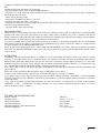
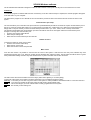
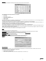
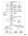
Ver. 3.3
VproX 1000-M
1000 KEYS/TAGS SYSTEM - MULTIENTRANCES
DESCRIPTION
VproX 1000 is an advanced access control system based around the individual unique Videx Coded Contact Key or
Proximity Key giving over 4 billion combinations. System can handle up to 30 main doors ( 4 doors included on board )
and up to 100 apartment doors. All additional main doors and apartment doors need a local unit VproX 1000-A
(connected to the VproX 1000 system by 3 wires BUS shielded, for a max. distance of 500 mts and max. resistance of
10 Ohm).
Main features.
VproX 1000 system has the possibility:
~ to store up to 1000 keys/Tags.
~ to connect up to 8 Readers Module ART.847 / 848 for contact Key or ART.849 for Proximity Key ( 2 each main door)
and connection can be made by using 5 standard wires, not shielded, for a max. distance of 200 mts and max. resistance
of 10 Ohm.
~ to connect up to 16 additional main door ( by using VproX 1000-A coded from 105 to 120)
~ to connect up to 100 apartment unit (by using VproX 1000-A device)
~ to select which main door the key/Tag can access (up to 20 doors, 4 included on board and 16 additional main door by
using VproX 1000-A device)
~ to select which apartment door the key/Tag can access
~ to select one of 4 "time band" during which it will be possible to entry
~ to store one or more Master key/Tag (with it, it is possible to entry everywhere)
~ to store more than one key/Tag each apartment (no limit)
~ to store the same key/Tag in difference apartments
~ to open main door and apartment door with the same key/Tag
~ to modify the setting parameters of a stored key/Tag
~ to delete a lost key/Tag
~ to keep in memory the last 512 accesses (Data Report), scroll them directly on display or download them in a printer or
a PC.
~ to connect a Videx printer Art.450 (by 25pole connector) to read out:
- No. of key/tag (3 digits: from 0 to 999 or ??? when not stored)
- No. of key/Tag where it allows to entry (2 digit: from 01 to 99 or "M" if it is a Master key/Tag)
- No. of main door (2 digits: from D1 to D20) or No. of apartment unit (2 digits: from U01 to U99)
- Qualification of the key/Tag ( 1 character: Y=yes, N=no)
- Time of access (hh:mm)
- Date of access (MM/DD)
~ to connect a PC (by 9pole connector standard RS232 interface and a program disk):
- to write the users name on a Database
- to have all data report stored in a file (on Diskette or Hard Disk)
- to see on screen (or to print ) all data report with the respective user name
- to see on screen (or to print ) the data report about only a single key/Tag
~ to connect an additional Button to close Relay 1 contact for programmed time
~ to connect an ALARM unit
Highest protection against sabotage: the Control Unit " VproX 1000" (with built in all relays) is remote from the Readers
Art.847/848/849; after 5 attempts with unstored or not qualified key/Tag, an alarm will be caused (ALARM relay will be
on) and the Control Unit will disable all Readers (self protection) for programmed time, all data will be stored into own
memory, or paper by printer (if installed) or PC (if connected).
High protection of Key/Tag DATA: all Key/Tag DATA are stored in two different memory (EEPROM); one remain on
VproX 1000 board (colour BLACK) and one can be use as spare (colour RED) in case something will happen to the first
one.
1
VP1K3.3-UK
System has a DISPLAY that shows all data during programming mode; while during "stand by" it displays the time and
date.
System has a keypad 4x4 buttons for following:
- Program Master code to access to the programming menu
- Program up to 1000 keys/Tags with possibility to select which apartment door, which main door and in which "time
band" the key/Tag can access
- Delete one or more keys/Tags
- Program the ALARM relay time ( 1-255 secs)
- Program each other relay time ( 1-255 secs)
- Program 4 "time band" ( hh:mm START, hh:mm STOP and week DAY each) during which it will be possible to use a
stored keys/Tags with this facility
- Program "Hours, Date and week Day".
INITIALIZATION
Note: In order to avoid electric discharges which could give problems to the system, we suggest not to install the cables
together with other power lines (AC electric lock cables, mains cables, lift cables, etc) or use a shielded cable for the
Readers connection and for the BUS line. When the installation is concluded and carried out according to wiring diagram,
place the jumper J1 (battery back-up for Clock/Calendar) in ON position.
If you have installed some VproX 1000-A units, you must set in binary code its Dip-switch bank (No. of Unit and Relay
time) before power up the system. To program it as an Apartment Unit you have to choose Nr. from 1 to 99 and from 105
to 120 to program it as an additional Main door Unit .
Power up the System and program it by " VproX 1000 PROGRAMMING" Flow Chart. Then, power off the System and
disconnect the "BACKUP MEMORY" (keep it in a safe place). At the end, power up the System and the VproX 1000 is
ready to work.
OPERATION
In stand by operation the System shows on DISPLAY the current TIME and DATA; when a user inserts a "stored
key/Tag" in a Reader (Main door or Apartment door) , the Printer (if present) will print the operation, the LEDs on
Reader will be green and a sharp "beep" will give out. If it's not a "stored key/Tag" the display will show ‘???’, the LEDs
on Reader will be red and a low "beep" will give out; the Printer will print the operation with the "???" instead of key/Tag
No. . All Data Report will be stored into memory (Eeprom) present in the System.
If the "BUS FAIL" LED is ON means that there are problems in the serial BUS connection with the Apartment Unit
VproX 1000-A.
If the "PE" LED is ON means that the paper is empty or the Printer is not connect.
If you have the "internal Printer" Art.450, you can advance the paper by pressing "FF" button.
If you want to know if a key/Tag is stored, keep pressed "#" button ( Display will show "TEST KEY"), release button and
insert the unknown key/Tag ( DISPLAY shows the key/Tag number ); at the end repeat the same procedure to came back
in stand-by mode.
If you want to download all Data Report Memory (the last 512 accesses) you must press ‘D’ button on the keypad (
“REPORT? 1=LPT - 2=DISPLAY” on display) and press ‘1’ if you want to send all to the printer or press ‘2’ to scroll
them on display by using "*" button.
TECHNICAL SPECIFICATIONS
Storage capacity
Working voltage
Stand-by absorption
Operation absorption
Operation absorption with internal Printer
Working temperature
:1000 keys
: 12V d.c. +/- 10%
: about 350mA
: max. 450mA
: max. 1.5A
: -10 +50 C degrees
2
VP1K3.3-UK
VP1000 Windows software
The VP1000 Windows software is designed to allow the main features of the VproX 1000 key CPU to be carried out from a PC:
Installation :
To install the program run SETUP.EXE from the root directory on the CD. After the setup is complete, the VP1000 program will appear
in the start menu on your computer.
The first time the program is run it will ask for the communication port the VP1000 is connected to and the number of doors on the
system:Communication port setup
The communication port on the side of the Vprox1000 CPU (Labelled RS232) should be connected to a spare communications port on
the PC by means of a serial cable. When you run the program for the first time, it will prompt you to select the communications port.
Simply click on the port number you have connected the Vprox1000 CPU to (i.e. Com1, Com2, Com3 or Com4) and click OK.
The program will remember the communication port so this should not need to be done again unless the communication port is
changed. To change the communication port :
•
From the main screen select SETUP
•
Select the port settings tab
•
Select the new communications port and click OK
Number of doors
To setup the number of doors on the system :
•
From the main screen select setup
•
Select the No. of doors tab
•
Select the number of doors and press OK
Main screen
From the main screen it is possible to view the last five users of the system. It will show the door they used, whether they were
excepted through the door or not, there key number and the time/date they used the system. The last users line will be shown in green
if they entered the building and red if they were denied access. A photo of the last user can also be shown.
The main screen also shows the state of the door relays. (Either active [Green] or not active [Red]).
To the right of the screen are a number of buttons which allow you to navigate through the system :
User log : From here you can view a log of the users on the system. It is also possible to download the last 511 users from the CPU.
From here it is possible to setup the system as well as add, edit and delete users.
Setup :
User List : This screen will give you a list of all the users currently programmed into the system.
This is what you are reading now.
Help :
3
VP1K3.3-UK
User Log
The user log is a database containing records of all the users who have used the system.
For each user the following information is recorded :
•
User name
•
Key number
•
Door number accessed
•
Was access granted or denied?
•
Time of access
•
Date of access
From the user log page it is possible to download the last 511 log entries from the Vprox1000 CPU. To do this simply press the
download CPU log button and the download will commence.
To the left of the screen there are four buttons to navigate the database. These buttons are self explanatory.
The database has no limit to the number of records it can hold. So a DELETE button is also available to remove all records or a
selection of records to prevent the database using valuable hard drive space.
The FIND button allows you to find a particular user name or key number.
After viewing a particular key, to go back to the full database press the SHOW ALL RECORDS button.
If a hard copy is required for the user you are viewing or for all users, press the PRINT button. A standard print dialogue box will
appear. Simply choose the printer and press print.
Finally, when the UPDATE IN REAL TIME box is ticked, new entries will appear on the screen as they happen. If this box is not ticked,
the entries will be recorded in the database but will not appear on the screen.
Setup
The setup page is split into the following sections :
Port Settings [Choose the communications port which is to be connected to the Vprox1000 CPU] as shown on page 1
No. of Doors [Choose how many doors are on the system] as shown on page 1
Door Open Times [Set the door open times for the four main doors and the alarm relay time]
Time Bands [Set the four optional time bands]
Users [Add, Edit or Delete users from the system]
Download [Download the programming information stored in the Vprox1000 CPU]
Upload [Upload the information stored in the PC back to the Vprox1000 CPU]
Door open times
The door open times for doors 1 to 4 can be programmed to anything from 1 second to 255 seconds. All other doors can not be
programmed via the PC. To change the door open times :
•
From the main screen select setup
•
Select the Door open times tab
•
Enter the door open times in the boxes shown and press OK (i.e. 5 seconds = 5)
4
VP1K3.3-UK
Alarm relay time
The alarm relay time is the time the alarm relay on the CPU will stay active for. The alarm relay activates if a key that is not
programmed or does not have access through a certain door is used consecutively five times.
To change the alarm relay time :
•
From the main screen select setup
•
Select the Door open times tab
•
Enter the time in the box provided and then press OK. (i.e. 10 seconds = 10)
Time bands
There are four time bands available on the Vprox1000 system. These are labelled A, B, C & D. Each time band has a start time, a stop
time and a day option. The day option means the time band can be set to work on all days, a single day, week days or weekends.
To change the time bands :
•
From the main screen select setup
•
Select the Time bands tab
•
Use the drop down menus to select the times and days for each of the four time bands and then press OK.
Download from Vprox1000 CPU
It is necessary to download from the CPU every time you run the program. This is to prevent accidental loss of keys due to the
possibility that the CPU information has been changed since the last upload from the PC.
The following information is downloaded :
•
Programmed keys and access levels
•
Door open times
•
Time bands
To download from the Vprox1000 :
•
From the main screen select setup
•
Press Download from CPU.
•
A password box will appear. Enter the CPU master code (Factory default is 11111111). But this may have been changed at the
time of installation. The master code can only be changed from the CPU.
•
After entering the master code, press OK.
•
If the master code is correct, the progress of the download will be shown across the bottom of the screen.
Once the download is complete, all information from the CPU will be saved to the PC.
Upload to Vprox1000 CPU
It is necessary to upload to the CPU every time you add, edit or delete keys and when ever changes are made to door open times and
time bands. To Upload to the Vprox1000 :
•
From the main screen select setup
•
Press Upload from CPU.
•
A password box will appear. Enter the CPU master code (Factory default is 11111111). But this may have been changed at the
time of installation. The master code can only be changed from the CPU.
•
After entering the master code, press OK.
•
If the master code is correct, the progress of the upload will be shown across the bottom of the screen.
Once the upload is complete, all information from the PC will be saved to the CPU.
Add a new user
Adding a user requires the use of a reader module to read the key which is to be programmed into the system. Before you can add
users you must first download from the CPU if you have not already done so. To add a user to the Vprox1000 :
•
From the main screen select setup
•
Select the Users tab
•
Select Add a new user.
•
A new box will appear which will allow you to either press a button to show the next available key number or use a drop down menu
to show all available key numbers from which to choose one.
•
Once a key number has been selected, press the OK button.
•
A red window will appear which will ask you to put the key on the reader.
•
Once the key has been read the window will go green.
o At this point you will be asked to enter the users details which consist of :
•
The users name
•
The time band A, B, C, D or N for no time band
•
The unit number (Between 1 & 99 for apartment doors)
•
Path to users photo (Optional facility to add a users photo to the system) (*)note
•
Door access, (Select which door they may or may not use).
o After entering all the detail, press the Update database button to save the entry.
At this point you can either go back and add another key or upload the information to the CPU.
(*)note: The users photo should be approx. 3cm by 5cm. And stored on the computer as either a JPG or BMP image.
5
VP1K3.3-UK
Edit a user
When editing a user you can change the users name, there time band, there photo ID, there access level and there unit number. Before
you can edit users you must first download from the CPU if you have not already done so. To edit a user:
•
From the main screen select setup
•
Select the Users tab
•
Select Edit a user.
•
A new box will appear which will allow you to either search for the user you wish to edit by user name or by key number.
•
Once a user has been selected, press the OK button.
•
The users details will appear on the screen. It will now be possible to edit them.
•
After entering all the detail, press the Update database button to save the entry.
At this point you can either go back and edit another user or upload the information to the CPU.
Deleting a user
Deleting a user will completely remove them from the system. Before you can delete users you must first download from the CPU if you
have not already done so. To delete a user :
•
From the main screen select setup
•
Select the Users tab
•
Select Delete a user.
•
A new box will appear which will allow you to either search for the user you wish to delete by user name or by key number.
•
Once a user has been selected, press the OK button.
•
The users details will appear on the screen. A message box will appear asking you if you are sure you want to delete the user.
At this point you can either go back and delete another user or upload the changes to the CPU.
User List
The user list contains a list of all the users currently programmed into the system along with their key numbers. It also shows the
number of users on the system.
Navigating through the users is by means of a NEXT and BACK button. Each page will show 15 users. Press the NEXT button to show
the next 15 users, press the back button to show the previous 15 users. Press the PRINT button to obtain a hard copy.
Minimum system required
The SK1000 software is designed to operate on a Windows based PC with the following minimum specification :
•
Pentium processor 233MHz personal computer or higher.
•
Windows 95 or later
•
16MB RAM Memory
•
CD-ROM Drive
•
SVGA, 16 bit colour
•
Spare serial communications port
6
VP1K3.3-UK
7
VP1K3.3-UK
8
VP1K3.3-UK
VPROX 1000-A
REMOTE APARTMENT UNIT KEY SYSTEM
DESCRIPTION
System works with the VproX 1000 Unit through a Serial BUS interface (only 3 wires not shielded, for a max.
distance of 500 mts and max. resistance of 10 Ohm).
It is possible:
~ to connect on the same BUS more than 100 VproX 1000-A Units which, during initialisation, must be named
giving a distinguishing number (in BINARY code) by means of the 8 way Dip-switch bank present on the
board ( switches from Nr.1 to Nr.7 ).
~ to program it as an Apartment door Unit using Nr. from 1 to 99
~ to program it as an Additional Main door Unit using Nr. from 105 to 120 ( the real Nr. will be Additional
Main door from 5 to 20 )
~ to connect a Reader Module ART.847, 848 or 849 using 5 standard wires, not shielded, for a max. distance of
200 mts and max. resistance of 10 Ohm
~ to connect a Back-up Battery to guarantee the right operation in case of Mains failure (230V a.c.); at the end
the system will provide to charge it
~ to select the Relay output time from 2 to 5 sec.( by means 8th Dip-switch)
~ to connect an additional Button to close Relay 1 contact for programmed time
~ to supply directly d.c. or a.c. Lock (12V 1.6A max.)
- 9 Module Box facility.
- Red LED facility to signals a damage on the output stage connected with the BUS (in case of fault it helps to
find the damaged Unit).
- Self protection Alarm after 5 attempts with an unstored or not qualified keys: the Reader will be disable the
1st time for 10 sec. the 2nd 20 sec. and so on.
OPERATION
In stand-by operation, the system is ready to accept a key; when a user inserts a key in a Reader, the system, by
the Serial BUS, asks to the VPROX 1000 if the key is stored and qualified; if yes, the Reader will be green, a
sharp "beep" will give out and a Relay will be on for programmed time, if not, the Reader will be red and a low
"beep" will give out.
Technical specification
Working voltage
Stand-by absorption
Operation absorption with Electric Lock ON
Working temperature
: 230V a.c. +/- 10%
: approx. 3VA
: max. 20VA
: -10 +50 C degrees
9
VP1K3.3-UK
Table for decimal to binary conversion to program the VproX 1000-A
Decimal
Nr.
1
2
3
4
5
6
7
8
9
10
11
12
13
14
15
16
17
18
19
20
21
22
23
24
25
26
27
28
29
30
31
32
33
34
35
36
37
38
39
40
41
42
43
44
45
46
47
48
49
50
51
52
53
54
55
56
57
58
59
60
61
62
63
64
1
ON
OFF
ON
OFF
ON
OFF
ON
OFF
ON
OFF
ON
OFF
ON
OFF
ON
OFF
ON
OFF
ON
OFF
ON
OFF
ON
OFF
ON
OFF
ON
OFF
ON
OFF
ON
OFF
ON
OFF
ON
OFF
ON
OFF
ON
OFF
ON
OFF
ON
OFF
ON
OFF
ON
OFF
ON
OFF
ON
OFF
ON
OFF
ON
OFF
ON
OFF
ON
OFF
ON
OFF
ON
OFF
2
DIP-SWITCH Nr.
3
4
5
6
7
Decimal
Nr.
OFF OFF OFF OFF OFF OFF
ON OFF OFF OFF OFF OFF
ON OFF OFF OFF OFF OFF
OFF ON OFF OFF OFF OFF
OFF ON OFF OFF OFF OFF
ON ON OFF OFF OFF OFF
ON ON OFF OFF OFF OFF
OFF OFF ON OFF OFF OFF
OFF OFF ON OFF OFF OFF
ON OFF ON OFF OFF OFF
ON OFF ON OFF OFF OFF
OFF ON ON OFF OFF OFF
OFF ON ON OFF OFF OFF
ON ON ON OFF OFF OFF
ON ON ON OFF OFF OFF
OFF OFF OFF ON OFF OFF
OFF OFF OFF ON OFF OFF
ON OFF OFF ON OFF OFF
ON OFF OFF ON OFF OFF
OFF ON OFF ON OFF OFF
OFF ON OFF ON OFF OFF
ON ON OFF ON OFF OFF
ON ON OFF ON OFF OFF
OFF OFF ON ON OFF OFF
OFF OFF ON ON OFF OFF
ON OFF ON ON OFF OFF
ON OFF ON ON OFF OFF
OFF ON ON ON OFF OFF
OFF ON ON ON OFF OFF
ON ON ON ON OFF OFF
ON ON ON ON OFF OFF
OFF OFF OFF OFF ON OFF
OFF OFF OFF OFF ON OFF
ON OFF OFF OFF ON OFF
ON OFF OFF OFF ON OFF
OFF ON OFF OFF ON OFF
OFF ON OFF OFF ON OFF
ON ON OFF OFF ON OFF
ON ON OFF OFF ON OFF
OFF OFF ON OFF ON OFF
OFF OFF ON OFF ON OFF
ON OFF ON OFF ON OFF
ON OFF ON OFF ON OFF
OFF ON ON OFF ON OFF
OFF ON ON OFF ON OFF
ON ON ON OFF ON OFF
ON ON ON OFF ON OFF
OFF OFF OFF ON ON OFF
OFF OFF OFF ON ON OFF
ON OFF OFF ON ON OFF
ON OFF OFF ON ON OFF
OFF ON OFF ON ON OFF
OFF ON OFF ON ON OFF
ON ON OFF ON ON OFF
ON ON OFF ON ON OFF
OFF OFF ON ON ON OFF
OFF OFF ON ON ON OFF
ON OFF ON ON ON OFF
ON OFF ON ON ON OFF
OFF ON ON ON ON OFF
OFF ON ON ON ON OFF
ON ON ON ON ON OFF
ON ON ON ON ON OFF
OFF OFF OFF OFF OFF ON
65
66
67
68
69
70
71
72
73
74
75
76
77
78
79
80
81
82
83
84
85
86
87
88
89
90
91
92
93
94
95
96
97
98
99
100
101
102
103
104
105
106
107
108
109
110
111
112
113
114
115
116
117
118
119
120
121
122
123
124
125
126
127
10
1
DIP-SWITCH Nr.
2
3
4
5
6
7
ON OFF OFF OFF OFF OFF ON
OFF ON OFF OFF OFF OFF ON
ON ON OFF OFF OFF OFF ON
OFF OFF ON OFF OFF OFF ON
ON OFF ON OFF OFF OFF ON
OFF ON ON OFF OFF OFF ON
ON ON ON OFF OFF OFF ON
OFF OFF OFF ON OFF OFF ON
ON OFF OFF ON OFF OFF ON
OFF ON OFF ON OFF OFF ON
ON ON OFF ON OFF OFF ON
OFF OFF ON ON OFF OFF ON
ON OFF ON ON OFF OFF ON
OFF ON ON ON OFF OFF ON
ON ON ON ON OFF OFF ON
OFF OFF OFF OFF ON OFF ON
ON OFF OFF OFF ON OFF ON
OFF ON OFF OFF ON OFF ON
ON ON OFF OFF ON OFF ON
OFF OFF ON OFF ON OFF ON
ON OFF ON OFF ON OFF ON
OFF ON ON OFF ON OFF ON
ON ON ON OFF ON OFF ON
OFF OFF OFF ON ON OFF ON
ON OFF OFF ON ON OFF ON
OFF ON OFF ON ON OFF ON
ON ON OFF ON ON OFF ON
OFF OFF ON ON ON OFF ON
ON OFF ON ON ON OFF ON
OFF ON ON ON ON OFF ON
ON ON ON ON ON OFF ON
OFF OFF OFF OFF OFF ON ON
ON OFF OFF OFF OFF ON ON
OFF ON OFF OFF OFF ON ON
ON ON OFF OFF OFF ON ON
OFF OFF ON OFF OFF ON ON
ON OFF ON OFF OFF ON ON
OFF ON ON OFF OFF ON ON
ON ON ON OFF OFF ON ON
OFF OFF OFF ON OFF ON ON
ON OFF OFF ON OFF ON ON
OFF ON OFF ON OFF ON ON
ON ON OFF ON OFF ON ON
OFF OFF ON ON OFF ON ON
ON OFF ON ON OFF ON ON
OFF ON ON ON OFF ON ON
ON ON ON ON OFF ON ON
OFF OFF OFF OFF ON ON ON
ON OFF OFF OFF ON ON ON
OFF ON OFF OFF ON ON ON
ON ON OFF OFF ON ON ON
OFF OFF ON OFF ON ON ON
ON OFF ON OFF ON ON ON
OFF ON ON OFF ON ON ON
ON ON ON OFF ON ON ON
OFF OFF OFF ON ON ON ON
ON OFF OFF ON ON ON ON
OFF ON OFF ON ON ON ON
ON ON OFF ON ON ON ON
OFF OFF ON ON ON ON ON
ON OFF ON ON ON ON ON
OFF ON ON ON ON ON ON
ON ON ON ON ON ON ON
VP1K3.3-UK
11
VP1K3.3-UK