1
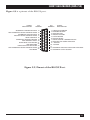
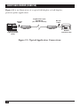
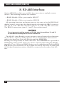
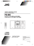
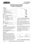
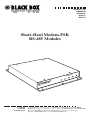
AUGUST 1997
ME840A-M
ME840A-S
MD3317
MD3318
Short-Haul Modem-FSK
RS-485 Modules
-FSK
SHM
R
K
R
CD
RxD
TxD
LPB
PW
R
CUSTOMER
SUPPORT
INFORMATION
Order toll-free in the U.S. 24 hours, 7 A.M. Monday to midnight Friday: 877-877-BBOX
FREE technical support, 24 hours a day, 7 days a week: Call 724-746-5500 or fax 724-746-0746
Mail order: Black Box Corporation, 1000 Park Drive, Lawrence, PA 15055-1018
Web site: www.blackbox.com • E-mail: [email protected]
FCC STATEMENT
FEDERAL COMMUNICATIONS COMMISSION
AND
INDUSTRY CANADA
RADIO FREQUENCY INTERFERENCE STATEMENTS
This equipment generates, uses, and can radiate radio frequency energy
and if not installed and used properly, that is, in strict accordance with the
manufacturer’s instructions, may cause interference to radio communication.
It has been tested and found to comply with the limits for a Class A
computing device in accordance with the specifications in Subpart J of
Part 15 of FCC rules, which are designed to provide reasonable protection
against such interference when the equipment is operated in a commercial
environment. Operation of this equipment in a residential area is likely to
cause interference, in which case the user at his own expense will be required
to take whatever measures may be necessary to correct the interference.
Changes or modifications not expressly approved by the party responsible
for compliance could void the user’s authority to operate the equipment.
This digital apparatus does not exceed the Class A limits for radio noise emission from
digital apparatus set out in the Radio Interference Regulation of Industry Canada.
Le présent appareil numérique n’émet pas de bruits radioélectriques dépassant les limites
applicables aux appareils numériques de classe A prescrites dans le Règlement sur le
brouillage radioélectrique publié par Industrie Canada.
3
INSTRUCCIONES DE SEGURIDAD
NORMAS OFICIALES MEXICANAS (NOM)
ELECTRICAL SAFETY STATEMENT
INSTRUCCIONES DE SEGURIDAD
1. Todas las instrucciones de seguridad y operación deberán ser leídas antes
de que el aparato eléctrico sea operado.
2. Las instrucciones de seguridad y operación deberán ser guardadas para
referencia futura.
3. Todas las advertencias en el aparato eléctrico y en sus instrucciones
de operación deben ser respetadas.
4. Todas las instrucciones de operación y uso deben ser seguidas.
5. El aparato eléctrico no deberá ser usado cerca del agua—por ejemplo,
cerca de la tina de baño, lavabo, sótano mojado o cerca de una alberca,
etc..
6. El aparato eléctrico debe ser usado únicamente con carritos o pedestales
que sean recomendados por el fabricante.
7. El aparato eléctrico debe ser montado a la pared o al techo sólo como
sea recomendado por el fabricante.
8. Servicio—El usuario no debe intentar dar servicio al equipo eléctrico más
allá a lo descrito en las instrucciones de operación. Todo otro servicio
deberá ser referido a personal de servicio calificado.
9. El aparato eléctrico debe ser situado de tal manera que su posición no
interfiera su uso. La colocación del aparato eléctrico sobre una cama,
sofá, alfombra o superficie similar puede bloquea la ventilación, no se
debe colocar en libreros o gabinetes que impidan el flujo de aire por los
orificios de ventilación.
10. El equipo eléctrico deber ser situado fuera del alcance de fuentes de
calor como radiadores, registros de calor, estufas u otros aparatos
(incluyendo amplificadores) que producen calor.
4
INSTRUCCIONES DE SEGURIDAD
11. El aparato eléctrico deberá ser connectado a una fuente de poder sólo
del tipo descrito en el instructivo de operación, o como se indique en
el aparato.
12. Precaución debe ser tomada de tal manera que la tierra fisica y la
polarización del equipo no sea eliminada.
13. Los cables de la fuente de poder deben ser guiados de tal manera que no
sean pisados ni pellizcados por objetos colocados sobre o contra ellos,
poniendo particular atención a los contactos y receptáculos donde salen
del aparato.
14. El equipo eléctrico debe ser limpiado únicamente de acuerdo a las
recomendaciones del fabricante.
15. En caso de existir, una antena externa deberá ser localizada lejos
de las lineas de energia.
16. El cable de corriente deberá ser desconectado del cuando el equipo
no sea usado por un largo periodo de tiempo.
17. Cuidado debe ser tomado de tal manera que objectos liquidos
no sean derramados sobre la cubierta u orificios de ventilación.
18. Servicio por personal calificado deberá ser provisto cuando:
A: El cable de poder o el contacto ha sido dañado; u
B: Objectos han caído o líquido ha sido derramado dentro
del aparato; o
C: El aparato ha sido expuesto a la lluvia; o
D: El aparato parece no operar normalmente o muestra un cambio
en su desempeño; o
E: El aparato ha sido tirado o su cubierta ha sido dañada.
5
SHORT HAUL MODEM (SHM-FSK)
TRADEMARKS
All applied-for and registered trademarks are the property of their respective owners.
6
SHORT HAUL MODEM (SHM-FSK)
CONTENTS
1. Specifications. . . . . . . . . . . . . . . . . . . . . . . . . . . . . . . . . . . . . . . . . . . . . . . . . . 8
2. Introduction . . . . . . . . . . . . . . . . . . . . . . . . . . . . . . . . . . . . . . . . . . . . . . . . . . 9
2.1 Master Units . . . . . . . . . . . . . . . . . . . . . . . . . . . . . . . . . . . . . . . . . . . . . 9
2.2 Remote Units. . . . . . . . . . . . . . . . . . . . . . . . . . . . . . . . . . . . . . . . . . . . . 9
2.3 Operating Modes . . . . . . . . . . . . . . . . . . . . . . . . . . . . . . . . . . . . . . . . 10
2.4 Diagrams . . . . . . . . . . . . . . . . . . . . . . . . . . . . . . . . . . . . . . . . . . . . . . . 10
3. Installation. . . . . . . . . . . . . . . . . . . . . . . . . . . . . . . . . . . . . . . . . . . . . . . . . . . 13
4. Operation . . . . . . . . . . . . . . . . . . . . . . . . . . . . . . . . . . . . . . . . . . . . . . . . . . . 15
5. Jumper Settings . . . . . . . . . . . . . . . . . . . . . . . . . . . . . . . . . . . . . . . . . . . . . . . 16
5.1 DCE and DTE Settings . . . . . . . . . . . . . . . . . . . . . . . . . . . . . . . . . . . . 16
5.2 Transmitter Output Level. . . . . . . . . . . . . . . . . . . . . . . . . . . . . . . . . . 16
5.3 Receiver Gain . . . . . . . . . . . . . . . . . . . . . . . . . . . . . . . . . . . . . . . . . . . 17
5.4 Carrier Detect . . . . . . . . . . . . . . . . . . . . . . . . . . . . . . . . . . . . . . . . . . . 17
5.5 Chassis Ground . . . . . . . . . . . . . . . . . . . . . . . . . . . . . . . . . . . . . . . . . . 17
5.6 Half Duplex Operation/Carrier Control . . . . . . . . . . . . . . . . . . . . . 17
6. LED Indications . . . . . . . . . . . . . . . . . . . . . . . . . . . . . . . . . . . . . . . . . . . . . . 18
7. General Operating Notes . . . . . . . . . . . . . . . . . . . . . . . . . . . . . . . . . . . . . . . 19
7.1 Tuned Circuits. . . . . . . . . . . . . . . . . . . . . . . . . . . . . . . . . . . . . . . . . . . 19
7.2 Proper Operation . . . . . . . . . . . . . . . . . . . . . . . . . . . . . . . . . . . . . . . . 19
7.3 Loopback Test . . . . . . . . . . . . . . . . . . . . . . . . . . . . . . . . . . . . . . . . . . . 19
8. RS-485 Interface . . . . . . . . . . . . . . . . . . . . . . . . . . . . . . . . . . . . . . . . . . . . . . 20
7
SHORT HAUL MODEM (SHM-FSK)
1. Specifications
Data Format — RS-232C (RS-422/485 optional)
Operation — Full-duplex or half-duplex controlled carrier,
serial asynchronous data
Mode — Point-to-point or multipoint
Data Transmission Speed — Up to 9600 baud
Modulation — Frequency shift key; carrier signal inductively
and capacitively isolated
Distance — Up to 48,000 feet (9.1 miles or 14.6 km) on single twisted pair
Operating Temperature — 32 to 140 °F (0 to 60 °C)
Enclosure — All-metal enclosure, 16 gauge steel; polyurethane paint
Interface — DTE/DCE jumper selectable; Female DB25 connector for
RS-232C; green two-position pluggable terminal block for carrier; black twoposition pluggable terminal block for power
LED Indicators — Carrier Detect, Receive Data, Transmit Data, Power
Power Requirements — 120 VAC 50/60 Hz at 9.6 watts or 24 VDC at 10 watts
Size — 1.75” H x 7.5” W x 10.5” D (4.45 x 19.1 x 26.7 cm)
Weight — 4.5 lb. (2 kg)
8
SHORT HAUL MODEM (SHM-FSK)
2. Introduction
The Short Haul Modem (SHM-FSK) is a private-line modem that allows
half- and full-duplex RS-232 data communications at 9600 bps over a single
dedicated wire pair and across sliding contacts. The SHM-FSK operates using
pure Frequency Shift Key (FSK) at high carrier frequencies (100KHz,
106.5KHz to 150KHz, 156.5KHz). These high frequencies make the
SHM-FSK particularly immune to crosstalk and outside noise interference,
providing highly reliable, continuous data transmission over distances
of several miles in harsh industrial environments.
The SHM-FSK converts digital signals to modulated high-frequency sinewave carrier signals that can be transmitted much longer distances, with
greater noise immunity, than square-wave digital signals. The digital Space
and Mark (or 0 and 1) are converted in the transmitter to carrier signals
having two slightly different frequencies that are identified by the receiver
and reconverted to the digital signals. The SHM-FSKs are configured as either
Master or Remote units and can be used for either point-to-point or multidrop data communications.
The SHM-FSKs send data asynchronously. They are transparent to protocol,
and to data rate from DC to 9600 baud.
The SHM-FSK can be configured as a master unit or as a slave unit.
See page 13 for more information.
2.1 SHM-FSK Master Units (part number ME840A-M)
The SHM-FSK Master unit transmits at 106.5/100 KHz (Space/Mark) and
receives at 156.5/150 KHz. A green pluggable two-position terminal block
at the back of the unit is used for connection to the data line. There is no
polarity to the data-line connection.
2.2 SHM-FSK Remote Units (part number ME840A-S)
The SHM-FSK Remote unit transmits at 156.5/150 KHz and receives at
106.5/100 KHz. It has the same data-line connector as the Master unit.
Both the Master and Remote SHM-FSKs are powered by nominal 24 volts
DC, which is supplied to a black two-position plugabble terminal block (+ on
the left, if you’re facing the pins) on the rear panel. The units are delivered
from the factory with 120VAC to 24DC wall transformers which have a black
plug attached. An external 24VDC supply can also be used to power up the
MDLs. The current draw is 250mA.
9
SHORT HAUL MODEM (SHM-FSK)
2.3 Operating Mode
The SHM-FSKs can be operated in either point-to-point or multipoint polling
mode.
For multi-drop data communications, the SHM-FSK can be operated with
one Master and typically up to eight Remote units. The transmitter in each
Remote unit is controlled by the intelligent device it is connected to. The
Master unit’s transmitter remains on all the time. The green two-position
pluggable terminal block at the receptacle marked “LINE” on the back of the
SHM-FSK unit is used with any two-wire cable (does not need to be twisted).
Since the FSK signal is AC, there is no polarity required on any of the dataline connections.
2.4 Diagrams
Figure 2-1 shows the location of the LEDs on the front of the SHM-FSK.
CD
RxD
TxD
LPBK
PWR
Figure 2-1. Location of LEDs on the SHM-FSK.
10
SHORT HAUL MODEM (SHM-FSK)
Figure 2-2 is a pinout of the RS-232 port.
SIGNAL
DESTINATION
PIN
NUMBER
PIN
NUMBER
14
15
16
17
18
19
20
21
22
23
24
25
1
2
3
4
5
6
7
8
9
10
11
12
13
SECONDARY TRANSMITTED DATA
DCE TRANSMITTER SIGNAL ELEMENT TIMING
SECONDARY RECEIVED DATA
RECEIVER SIGNAL ELEMENT TIMING
LOCAL LOOPBACK
SECONDARY REQUEST TO SEND
DATA TERMINAL READY
SIGNAL QUALITY DETECTOR
RING INDICATOR
DATA SIGNAL RATE SELECTOR
DTE TRANSMITTER SIGNAL ELEMENT TIMING
TEST MODE
SIGNAL
DESTINATION
PROTECTIVE GROUND
TRANSMITTED DATA
RECEIVED DATA
REQUEST TO SEND
CLEAR TO SEND
DATA SET READY
SIGNAL GROUND / COMMON RETURN
RECEIVED LINE SIGNAL DETECTOR
+ VOLTAGE
- VOLTAGE
SECONDARY RECEIVED LINE SIGNAL INDICATOR
SECONDARY CLEAR TO SEND
Figure 2-2. Pinout of the RS-232 Port.
11
SHORT HAUL MODEM (SHM-FSK)
Figure 2-3 is an illustration of a typical full-duplex or half-duplex,
point-to-point application.
Copper Pairs up to
48,000 feet
(9.1 miles or 14.6 km)
RS-232
Cable
SHM-FSK
RS-232
Cable
SHM-FSK
Remote
Telemetry Unit
Programmable
Logic Controller
(PLC)
Figure 2-3. Typical Application Connections.
12
SHORT HAUL MODEM (SHM-FSK)
3. Installation
The SHM-FSK units are shipped ready for either full-duplex or half-duplex
multi-drop operation. The jumpers have been factory-set in full-duplex mode.
The Master and Remote units are both factory-configured as DCEs (Data
Communications Equipment) with the jumpers on headers P1 and P2 in the
B-C position. Data into the DB25 is on pin 2 and data out is on pin 3. (Also
see Chapter 5, Jumper Settings.)
Before installing the SHM-FSK units, make sure that the digital devices to
be connected to the SHM-FSK units are capable of communicating with each
other if connected with a conventional three-wire RS-232 data cable. Once
this has been established, the devices can be connected to the SHM-FSK units
and RS-232 data communications will take place transparently.
NOTE
Make sure that the wire pair to be used for data communications between
SHM-FSK units is connected only to those units; has no branches; has
no attached inductance, capacitance, or resistance; and has no loading
coils, filters or any other load; and that all connections are clean and
solid. Since the data line is transformer-isolated from the rest of the
circuit, neither leg of the data-carrying twisted pair should be grounded.
The installation procedure is as follows:
1. Remove the unit’s cover by taking out the four screws on top of the
modem.
2. Set the Remote units for either full- or half-duplex operation by
positioning the jumper on header P4, located behind the DB25
connector. For full-duplex operation, the jumper should be in the B-C
position; for half-duplex, multi-drop operation using RTS line carrier
control, the jumper should be in the A-B position.
13
SHORT HAUL MODEM (SHM-FSK)
3. Confirm that the jumpers on positions P1 and P2 are in the B-C position.
4. Replace the cover.
5. Connect the RS-232 communications port of the digital data device
(PC, PLC, etc.) to the SHM-FSK unit with an appropriate cable.
6. Connect the transmission line to the unit at the green pluggable terminal
block. There is no polarity requirement.
7. Connect the unit’s power cord at the black two-position pluggable
terminal block marked “PWR” (facing receptacle, + is on the left and - on
the right) and plug the modular transformer into a convenient 120-VAC
outlet. Plugging the power in will power up the units; there is no “On-Off”
switch.
14
SHORT HAUL MODEM (SHM-FSK)
4. Operation
Point-to-point, full- or half-duplex operation is usually conducted with the
both the Master and Remote SHM-FSK carriers on all the time. This is
achieved by placing the P4 jumper in the B-C position and either not
connecting the RTS line (DB25 pin 4) to the SHM-FSKs or making sure that
the RTS line supplied by the devices connected to the SHM-FSK is either
floating or logic high.
In half duplex, multi-drop operating mode, with the P4 jumper in the
A-B position, the RTS line of the intelligent device that a Remote SHM-FSK
is connected to (PC, PLC, or RTU) is used to control the the SHM-FSK’s
transmitted carrier. When logic is low, the carrier is turned off; when logic is
high, the carrier is turned on. If the RS-232 cable is disconnected, the RTS
connection on the SHM-FSK is biased low and the carrier remains off. (If the
P4 jumper is in the B-C position, the RTS connection is biased high and the
carrier will stay on.)
When properly configured, the SHM-FSK is capable of half- or full-duplex
data transmission at rates up to 9600 baud. The SHM-FSKs require no settings
for data rate and will operate transparently as data is fed to them. They will
begin communicating data as soon as connections are made and they are
powered up.
15
SHORT HAUL MODEM (SHM-FSK)
5. Jumper Settings
There are several configuration options that can be selected by jumpers as
described below. The jumper pins are internal and are identified by lettering
on the circuit board. They are accessed by removing the four retaining screws
on the top cover of the enclosure and removing the cover. Be sure that the
unit is disconnected from power before removing the cover.
5.1 DCE and DTE Settings
Both the SHM-FSK Master and Remote units are configured at the factory
as DCE (Data Communication Equipment) for connection to DTE (Data
Terminal Equipment). A PC, PLC, or multiplexor is usually configured as
DTE. If either the Master or Remote must be changed from DCE to DTE,
move the jumpers on blocks “P1” and “P2,” which are located directly behind
the DB25 RS-232 connector on the rear panel.
5.2 Transmitter Output Level
The SHM-FSK allows the selection of either normal or high-power (HP)
transmitter output. The high-power output has six times greater peak-to-peak
transmitted signal and provides correspondingly greater signal-to-noise ratio.
High-power transmitter operation is generally best in applications involving
sliding contacts or in very noisy EMI environments. However, caution is
advised in some cases since high power carrier signals will result in more
crosstalk to adjacent conductors.
The jumper to select normal or high power is located at position TP2. High
power is selected when the jumper is positioned center to left (marked “H”);
normal output is selected with center to right (marked “N”). When using the
HP setting, the receiver gain should be set to low for data-line lengths under
5000 feet. (see Section 5.3). The factory setting is normal (center to right,
“N”).
16
SHORT HAUL MODEM (SHM-FSK)
5.3 Receiver Gain
The SHM-FSK incorporates a receiver amplifier on the circuit board. This
amplifier has low, normal, and high gain settings configured by a “T” shaped
pin block near the center of the circuit board with pins marked “G1/H,”
“G2,” “G3/L,” and “N” (the leg of the “T”). G1/H-G2 is the high-gain setting;
G2-N, the normal medium gain; and G3/L-G2, the low gain. The units are
delivered from the factory set at normal gain because the transmitter has
been factory-set at normal output. If the data line is under 5000 feet long, the
low-gain setting should be used whenever the high- power transmitter option
is selected.
5.4 Carrier Detect:
Carrier Detect to the RS-232 connector is enabled or disabled by Jumper
Matrix P3. The SHM-FSK units are shipped with the Carrier Detect enabled
(jumper on).
5.5 Chassis Ground
Chassis ground can be connected to signal ground via Jumper P5. This
is generally not recommended. A separate chassis ground wire may be
connected to the SHM-FSK’s metal enclosure by means of any of the
cover mounting screws as desired to avoid a possible shock hazard.
5.6 Half-Duplex Operation/Carrier Control
The SHM-FSK can be operated in multi-drop/half-duplex mode by
controlling the transmitter’s carrier on/off using external signals. The most
common external carrier-control signal is through the RS-232 port RTS line
(pin 4). This line are selected by Jumper P4, A-B. When an external RTS logic
high is asserted, the SHM-FSK carrier is turned on; logic low or ground turns
the carrier off. The SHM-FSK RTS line is biased low, so that if the RS-232
cable is disconnected or the external controlling device is turned off, the
carrier will go off. A-B selects RTS and B-C selects DSR. Usually only the
Remote units have their carriers controlled by the devices they are connected
to. The Master unit’s carrier is left on all the time. (There is no interference,
since the Master and Remote carrier frequencies are different.)
The factory setting for both SHM-FSK Masters and Remotes is P4, A-B,
for full- or half-duplex point-to-point operation.
An alternative carrier-control method is to connect a cable to the SW1
header, which allows external contact closure or solid-state switch control
of the transmitter. Please call technical support for special instructions.
17
SHORT HAUL MODEM (SHM-FSK)
6. LED Indications
There are four LEDs on the front panel of the SHM-FSK. From left to right
they are:
Marking
Function
CD
Carrier Detect
RX
Data flowing out of the SHM’s RS-232 port
TX
Data flowing into the SHM’s RS-232 port
PWR
Power connected
The first diagnostic LED is Carrier Detect. In full-duplex mode, the CD
LED must be ON on both units; in half-duplex, carrier-control mode, with RS232 cables connected, the CD LED will be ON on all Remote SHMs and OFF
on the Master SHM. (The Master CD LED will blink during operation as each
Remote SHM turns on its carrier to answer back to the Master). If the correct
CD LEDs are not ON, there is likely a carrier cable problem.
Assuming that the CD indication is correct, a loopback test is recommended
as described in Section 7.3.
18
SHORT HAUL MODEM (SHM-FSK)
7. General Operating Notes
7.1 Tuned Circuits
The SHM-FSK uses tuned circuits to achieve its high performance. These
circuits have been carefully adjusted at the factory to operate over several
miles of transmission line. In order not to degrade performance, it is
important not to disturb these adjustments. In particular, coils T1, T2, T3,
T4, and T5 and potentiometers R18, R20, R31 and R57 should not be
adjusted. If these adjustments have been inadvertently changed, call for
technical support.
7.2 Proper Operation
Proper operation of SHM-FSK requires that the transmission line be nonloaded (free from inductors and capacitors on the line). The presence of
inductors, capacitors or excessive resistance (from bad connections, for
example), or shorts between the wires can seriously degrade performance
or completely block data transmission.
7.3 Loopback Test
A loopback test is suggested to confirm the proper operation of SHM-FSKs
in point-to-point operation, as follows:
A PC running a communication program in full duplex can be connected
to one of the SHM-FSKs in a point-to-point configuration. A jumper wire (a
bent paper clip works very well) is placed between pin sockets 2 and 3 of the
DB25 on the other SHM-FSK. Data sent to the first SHM-FSK will be looped
back from the second and appear on the PC screen. If the characters are
correct, the SHM-FSKs are functioning.
19
SHORT HAUL MODEM (SHM-FSK)
8. RS-485 Interface
Optional RS-485 modules are available for connection to multiple remote
devices. The following modules are available:
• RS-485 Module 2-Wire, part number MD3317
• RS-485 Module, 4-Wire, part number MD3318
All operating functions and instructions are the same as for the RS-232 full
duplex version, except that the digital interface through the DB25 connector
uses pin 12 as the -DO/RI connection and pin 13 as the +DO/RI connection.
The RS-232 connections (pins 2, 3 and 7) are not functional.
CAUTION
Do not connect anything except an RS-485 signal to positions 12 and 13
on the DB25 or damage to the circuit could occur.
The AE-485 (Auto Enable) circuit contains a special feature that eliminates
the need for a separate enable signal or line to command the 485 transmit
and receive functions. Data will pass through the SHM-FSK’s
RS-485 port transparently in either direction. The SHM-FSKs are operated in
full-duplex point-to-point mode (no carrier control) when using the AE-485
interface. Up to 32 remote RS-485 devices can be multi-dropped off the SHMFSK AE-485 port at distances of up to 4000 feet and at data rates of 9600 baud.
A 100-ohm termination resistor should be connected at the ends of the 485
line.
20
© Copyright 1997. Black Box Corporation. All rights reserved.
1000 Park Drive • Lawrence, PA 15055-1018 • 724-746-5500 • Fax 724-746-0746