1
Section 61291006L2-5
Issue 2, June 1999
CLEI Code #D4D3MPY_ _ _
Model TROCU DP Preferred Option
Total Reach® All-Rate DDS Dataport
Installation and Maintenance
SW1
CONTENTS
1. GENERAL ..................................................................... 1
2. OPTIONS ...................................................................... 2
3. INSTALLATION ........................................................... 3
4. TESTING ....................................................................... 3
5. REMOTE PROVISIONING AND
DIAGNOSTICS ............................................................. 4
6. DEPLOYMENT GUIDELINES .................................... 5
7. WARRANTY AND CUSTOMER SERVICE ............... 6
CU2DP
TRO
6L
129100
IRE
SD4 2-W
SYNC
LOSS
NEAR
CRC
SC
64
56
19.2
9.6
4.8
2.4
SW56
FAR
CRC
REM
QM
DISC
NO
DSU
AP
LBK
IDLE
Rx
(OUT)
FIGURES
Figure 1. TROCU DP Preferred Option ............................. 1
Figure 2. Total Reach DDS Circuit Diagram ..................... 1
Figure 3. Option Switch ..................................................... 2
Figure 4. Rate Selection ..................................................... 2
Figure 5. OCU Loopback at the TROCU DP ..................... 4
Figure 6. TROCU DP Bidirectional Loopback
Pass-Thru Mode ................................................. 4
Figure 7. TROCU DP Bidirectional Loopback
Normal Mode ..................................................... 4
Tx
(IN)
L
O
G
I
C
Figure 1. TROCU DP Preferred Option
traditional four-wire Alternate Mark Inversion (AMI)
signal for presentation to the customer.
TABLES
Table 1. Preprovisioning ..................................................... 3
Table 2. Cable Type Loss Data @ 13.3 kHz ....................... 3
Table 3. LED Indicators ..................................................... 5
Table 4. TRDDS Insertion Loss Measurements ................. 5
The TROCU DP occupies a single channel position in
the WECO® compatible D4 channel bank or the
AT&T® SLC-96 Mode I and III terminal. It provides
the interface between a DS0 timeslot of the T-carrier
data stream, and the two-wire metallic loop extending
to the customer premises.
1. GENERAL
This practice provides installation and maintenance
procedures for the ADTRAN D4 Total Reach Office
Channel Unit Dataport (TROCU DP) Preferred
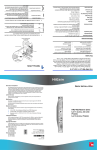
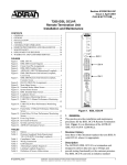
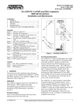
Option. The unit is illustrated in Figure 1.
The TROCU DP may interoperate over the carrier
system with another TROCU DP, an OCU DP, a DS0
DP, a 1/0 DCS, or the central office switch. The unit
can be located in an end office, hub office,
intermediate office, or remote terminal digital carrier
system (see Figure 2). The two-wire loop is
connected using the tip (pin 24) and ring (pin 51) on
the D4 backplane.
Document Revision History
Issue 2 of this document revises the Deployment
Guidelines subsection.
Description
ADTRAN D4 TROCU DP Preferred Option is a
functional replacement for the D4 OCU DP,
delivering data at rates up to 64 kbps on a single
copper pair. Used in combination with the Total
Reach Digital Data Service Remote termination unit
(TRDDS-R), the TROCU DP can accommodate
extended loop lengths eliminating the need for DDS
repeaters. The TROCU DP span powers the remote
TRDDS-R located at the customer premise. The
TRDDS-R converts the two-wire signal to the
61291006L2-5B
D4 or SLC-96
T-Carrier
TR
OCU
DP
Customer Premises
4-Wire Customer
Interface
2-Wire Loop
TRDDS-R
DSU/CSU
T/R Pair
Figure 2. Total Reach DDS Circuit Diagram
Trademarks: Any brand names and product names included in this document are
Section 61291006L2, Issue 2
trademarks, registered trademarks, or trade names of their respective holders.
1
NOTE
The TROCU DP must be used with an
appropriate TRDDS-R unit.
Features
In addition to operation over extended ranges the
TROCU DP incorporates or supports the following:
•
•
•
•
•
•
•
•
Two-wire deployment.
Repeaterless operation.
Bridged tap tolerant
Span power for remote TRDDS-R termination
unit.
Utilization in all D4 channel bank and SLC-96
Mode I or III remote terminal applications.
NEAR and FAR logic level bantam test access.
Loop Quality Monitor and A/B signaling
options.
Embedded Digital System 6 capabilities for
remote provisioning, configuration, and
performance monitoring.
CAUTION
Select only one option rate. Rate is selected on
faceplate switch SW2 by pushing one or two
switches to the right toward the inscribed
rates. If either SW56 or 64 is selected, the
secondary channel (SC) switch may not be
selected.
A/B Signaling
When A/B Signaling (SW1-1) is OFF, the unit derives
signaling from the incoming data stream. When A/B
signaling is ON, the unit determines the state of the A
and B signaling bits using signals present on the
backplane of the channel bank. This method assumes
that proper signaling has been maintained throughout
network tandems and cross connect systems.
NOTE
A/B option is only applicable when SW56 is
selected; otherwise the option is a “don’t care.”
Quality Monitor
When Quality Monitor (SW1-2) is ON, the unit
monitors the incoming two-wire loop and four-wire
customer interface data for errors. If excessive errors
are detected, the unit blocks customer data
transmission and sends Abnormal Station Code to the
network. Customer data transmission is automatically
restored when the trouble condition is cleared. The
Quality Monitor feature is recommended for use on
multipoint circuits.
3
1
2
A/B Signaling
Quality Monitor
4
5
ON
2
2
SW1
OFF
OFF
1
Sealing Current
The TROCU DP provides a constant 10 mA sealing
current to the TRDDS-R. With 10 mA sealing current
and span power of -130 Vdc, ADTRAN’s TRDDS
system is in the A3 Class as specified in Bellcore
TR-NWT-001089, Standard for Electrical Safety for
Network Telecommunications Equipment.
6
7
Line Code
The ADTRAN TRDDS incorporates Simple CodedPulse Amplitude Modulation (SC PAM), a line code
that reduces the bandwidth needed to transport signals
over copper loops. The Power Spectrum Density
(PSD) of SC PAM complies with Basic Rate Interface
(BRI) PSD mask as specified in ANSI T1.601 and is
below allowable 2B1Q PSD levels. SC PAM
increases the deployment ranges and allowable
bridged tap lengths when compared to AMI and
2B1Q. Additionally, SC PAM has an improved
spectral compatibility when compared to AMI and
2B1Q.
2. OPTIONS
Select the appropriate OPTIONS and RATE using
SW1 and faceplate switches as illustrated in Figure 3
and Figure 4.
8
NOTE
Do not use in SLC-96 Mode II unless unit is
provisioned through Digital System-6.
SC
64
56
19.2
9.6
4.8
2.4
SW56
ON
Figure 3. Option
Switch
Section 61291006L2, Issue 2
Figure 4. Rate
Selection
61291006L2-5B
In lieu of option switches, the TROCU DP Preferred
Option has been preprovisioned with feature settings
as indicated in Table 1.
Table 1. Preprovisioning
Feature
Setting
Latching Loopback
Zero Code Suppression
Error Correction
ON
ON (Unless 56 kbps, SC, and
64 kbps = OFF)
OFF
When inserted into a powered up backplane the
TROCU DP and TRDDS-R will synchronize within 30
to 90 seconds. When synchronized, the SYNC LOSS
indicator LED will turn Off. If synchronization cannot
be achieved, check the T/R pair for an open circuit or
short circuit condition, or load coils (see LED
Indicators).
4. TESTING
Testing for the TROCU DP is accomplished using the
same test procedures for four-wire OCU and OCU DP
units. Table 2 describes cable loss for the TRDDS
Nyquist frequency of 13.3 kHz.
The TROCU DP is equipped with logic level bantam
test access jacks that permit testing in both directions
using a portable test set. Latching and alternating OCU
and CSU loopback sequences are supported.
Alternating loopbacks do not operate when the 64
kbps data rate is selected. Choose NEAR to test
toward the customer loop; choose FAR to test toward
the T-carrier.
3. INSTALLATION
C A U T I O N !
SUBJECT TO ELECTROSTATIC DAMAGE
OR DECREASE IN RELIABILITY.
HANDLING PRECAUTIONS REQUIRED.
The TROCU DP plugs directly into a WECO or
equivalent D4 channel bank or the ADTRAN ACT
1900/2300 channel bank. No special wiring is
required. The two-wire loop uses the T/R (Tip and
Ring) pair, pins 24 and 51 of the D4 backplane.
In the FAR direction, an OCU loopback sequence will
loop the unit directly across the T-carrier system. In
the NEAR direction, an OCU loopback sequence will
loop the unit directly connected to the portable test set.
Span-powering is accomplished using -130 V,
measured from Tip to Ring. Voltage measured from
Tip to GND should indicate approximately -130 V;
voltage from Ring to GND should indicate
approximately 0.0 V.
NOTE
If 64 kbps is selected, the unit will only respond
to latching loopback sequences. Alternating
sequences are not valid at this rate.
Table 2. Cable Type Loss Data @ 13.3 kHz
Plastic Cable
dB Loss/kft
Paper Cable
dB Loss/kft
19 Gauge PIC (0F)
19 Gauge PIC (70F)
19 Gauge PIC (120F)
0.5302
0.6083
0.6610
19 Gauge PULP (0F)
19 Gauge PULP (70F)
19 Gauge PULP (120F)
0.5616
0.6415
0.6955
22 Gauge PIC (0F)
22 Gauge PIC (70F)
22 Gauge PIC (120F)
0.912
1.0258
1.1015
22 Gauge PULP (0F)
22 Gauge PULP (70F)
22 Gauge PULP (120F)
0.9454
1.0606
1.1370
24 Gauge PIC (0F)
24 Gauge PIC (70F)
24 Gauge PIC (120F)
1.2571
1.3982
1.4917
24 Gauge PULP (0F)
24 Gauge PULP (70F)
24 Gauge PULP (120F)
1.2900
1.4324
1.5268
26 Gauge PIC (0F)
26 Gauge PIC (70F)
26 Gauge PIC (120F)
1.6823
1.8568
1.9718
26 Gauge PULP (0F)
26 Gauge PULP (70F)
26 Gauge PULP (120F)
1.6751
1.8469
1.9608
61291006L2-5B
Section 61291006L2, Issue 2
3
As an enhancement to automated testing capability,
TRDDS eliminates false error indication when
invoking NIE, CSU, or DSU loopbacks immediately
following release of OCU loopback.
TROCU DP Bidirectional Loopback Support
The TROCU DP will execute a bidirectional loopback
when performing an OCU loopback at the TROCU
DP as shown in Figure 5. If the TRDDS-R detects a
bidirectional loopback during power-up
synchronization, the TRDDS-R allows data to pass on
the four-wire interface by entering into the pass-thru
mode. This allows a standard portable DDS test set,
connected to the four-wire customer interface of the
TRDDS-R, to verify the integrity of the two-wire loop
by transmitting a test pattern and examining the
returning data for synchronization and errors. The
TROCU DP LBK LED will illuminate solid during an
OCU loopback. Refer to Figure 6 for an illustration
of the bidirectional loopback pass-thru mode.
TROCU DP
Intra-office
Customer
Bidirectional
loopback
Figure 5. OCU Loopback at the TROCU DP
TROCU DP
TRDDS-R
X
X
DSU/CSU
Open Loop
Bidirectional
loopback
Figure 7. TROCU DP Bidirectional Loopback
Normal Mode
5. REMOTE PROVISIONING AND
DIAGNOSTICS
Control Protocol
Remote access to provisioning and status information
is accomplished using ADTRAN Digital System 6
Message protocol, defined in Control and Diagnostic
Procedures Practice, Section 6032991-6. Digital
System 6 is supported by the TPI 108/109 and 105
portable test set and is supported by Hekimian React
2001 Release 1.900 remote test system. The TRDDS
network elements comply with ANSI T1.107-1995,
“Digital Hierarchy Format Specifications Annex G”
which allows remote provisioning, querying, and
performance monitoring via inband control of network
elements.
NOTE
The REACT 2001 GUI software Release 1.900
supports ANSI T1.107-1995.
TROCU DP
TRDDS-R
Test Unit
Data
Pass-Thru
Bidirectional
loopback
Figure 6. TROCU DP Bidirectional Loopback
Pass-Thru Mode
If the TROCU DP bidirectional loopback is invoked after
the TRDDS-R achieves synchronization, the TRDDS-R will
not pass or receive data from the CPE or DDS test set. This
is consistent with current DDS testing methods and is
referred to as the TROCU DP bidirectional loopback normal
mode. For testing purposes, the installer may choose to
initiate the TRDDS-R to pass-thru mode. Once the
bidirectional loopback is executed in normal mode, unseat
and reseat the TRDDS-R and allow the unit to train-up.
Once trained, the TRDDS-R will revert to pass-thru mode
for further testing. Refer to Figure 7 for TRDDS operation
during bidirectional loopback in normal mode.
4
Remote access is accomplished using a defined set of
inband DS0 byte sequences similar to the latching
loopback sequence. Commands issued through the test
system are recognized by the individual channel unit,
which responds with the appropriate byte sequences.
These inband commands may be used to verify
options via dialogs with REACT 2001 and
TPI 108/109 test sets. Unit CLEI, serial number,
provisioning, and performance information can be
retrieved remotely using the Digital System 6
protocol.
Provisioning and Status
All configuration options can be remotely viewed or
provisioned. The front panel Remote (REM) LED
indicator will Flash during control link establishment
and remains ON after the channel unit has been
remotely provisioned.
If the channel unit has been remotely provisioned, the
operator can alternate between remote configuration
Section 61291006L2, Issue 2
61291006L2-5B
and manual switch settings by pressing the
momentary Alternate Provisioning (AP) switch
located on the front panel. If the channel unit is
removed from the system, the unit retains previous
provisioning information in nonvolatile Random
Access Memory (RAM).
The REM indicator remains ON when the channel
unit is operating based on Remote Provisioning, and
is OFF when operating on manual switches. If the
channel unit has never been remotely provisioned, the
AP switch has no effect and the REM indicator
remains OFF. See Table 3 for LED Indicators.
6. DEPLOYMENT GUIDELINES
The TROCU DP and TRDDS-R use technology
designed to eliminate the need for repeaters and
concerns over impairments caused by typical noise and
bridge tap. Table 2 describes cable loss for the
TRDDS Nyquist frequency of 13.3 kHz. Listed below
are the loop design guidelines for TRDDS (See Tables
2 and 4 for more information).
•
•
All loops must be nonloaded.
Actual Measured Loss (AML) should not
exceed 50 dB at 13.3 kHz (135 Ω termination),
the Nyquist frequency of TRDDS.
Table 3. LED Indicators
INDICATOR
NOTE
The 50 dB AML limit includes 6 dB of signal
margin to account for potential near-end cross
talk (NEXT) from other digital services that
may be provisioned in the same binder group.
DESCRIPTION
SYNC L OS S
ON indicates that there is no sync
between the TROCU DP and the
remote TRDDS-R; check for
continuity, load coils, and other
abnormal line conditions.
NEAR CRC
ON indicates that there are errors
on the incoming data stream;
check for the abnormal line
conditions closer to the TROCU
DP.
•
•
•
FAR CRC
ON indicates that there are errors
occurring towards the remote
TRDDS-R; check for the
abnormal line conditions closer to
the TRDDS-R.
•
REM
ON indicates that the unit has
been remotely provisioned;
FLASHING indicates that the
remote control link is active.
Push the AP button to toggle
between manual and remote
provisioning.
QM DISC
ON indicates that the Quality
Monitor Disconnect has occurred.
NO DSU
ON indicates the absence of the
customer DSU/CSU as
determined by the TRDDS-R.
LBK
ON indicates the OCU or CSU
loopback activation.
IDLE
ON indicates the presence of the
Control Mode Idle toward the
network.
61291006L2-5B
Loop length should not exceed 50 kft.
Bridged tap length should not exceed 12 kft.
Background noise level should not exceed 34
dBrn.
Impulse noise level should not exceed -40 dBm,
(+50 dBrn).
NOTE
Measure noise with 50 kbit weighting
characteristic approximating a filter with a
passband of 40 Hz to 30 kHz. Background
noise level or impulse noise level is referenced
from 56/64 kbps data rate in TR62310.
Table 4. TRDDS Insertion Loss Measurements
TRDDS
13.3 kHz compared to 28 kHz for traditional
DDS service
Line
Configuration
@ 13.3 kHz
@ 28 kHz
27 kft 26 AWG
50.12 dB
65.35 dB
36.25 kft 24 AWG
50.00 dB
62.50 dB
50 kft 22 AWG
50.24 dB
59.33 dB
Section 61291006L2, Issue 2
5
7. WARRANTY AND CUSTOMER SERVICE
ADTRAN will replace or repair this product within 10
years from the date of shipment if it does not meet its
published specifications or fails while in service (see:
ADTRAN Carrier Networks Equipment Warranty,
Repair, and Return Policy and Procedure, document:
60000087-10A).
Contact Customer And Product Service (CAPS) prior
to returning equipment to ADTRAN.
For service, CAPS requests, or further information,
contact one of the following numbers:
ADTRAN Technical Support
(800) 726-8663
Standard hours: Monday-Friday, 7 a.m.-7 p.m. CST
Emergency hours: 7 days/week, 24 hours/day
ADTRAN Sales
(800) 827-0807
ADTRAN Repair/CAPS
(256) 963-8722
Repair and Return Address
ADTRAN, Inc.
CAPS Department
901 Explorer Boulevard
Huntsville, Alabama 35806-2807
6
Section 61291006L2, Issue 2
61291006L2-5B