1
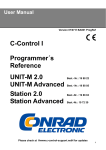
© 2007. All rights reserved.
Black Box Corporation.
Black Box Corporation • 1000 Park Drive • Lawrence, PA 15055-1018 • Tech Support: 724-746-5500 • www.blackbox.com • e-mail: [email protected]
PRO SWITCHING SYSTEM II
Control hundreds or thousands of devices
from a single ASCII terminal or PC!
Key Features
Chassis-mounted
switching and patching system for RS-232,
RS-530, X.21, and V.35
data communications.
Cards for A/B
switching and
patching or for switchonly capabilities.
Daisychain up to 9901
fully populated chassis
to control and manage
up to 158,416 A/B
interface cards.
Management Control
Software makes onscreen control a snap.
Multiple programmable
alarms alert you to
network conditions.
Dual-power options.
1
12/18/2007
#25900
anaging switchable circuits is
easy with the Pro Switching
System II (PSSII) from Black Box.
This innovative system consists
of rackmount modular components
that provide an economical and
reliable means to manage
RS-232/V.24, V.35, X.21, and RS-530
data interfaces. With this chassismounted switching and patching
system, you can switch individual
circuits, all 16 circuits in a chassis,
or a group of circuits via remote
console commands or upon an
alarm automatically.
You can also switch manually.
Use front-panel buttons to switch
individual circuits or to gangswitch. Or you can disable manual
switching capabilities in the system
with a simple command from an
attached console. We even offer a
Contact Closure Card that lets you
use a programmable logic
controller (PLC) to direct your
circuit switching.
Daisychain up to 9901 chassis
together to control and manage
158,416 A/B interface cards from
M
a single console. This means of
control is an alternative
to connecting multiple multiport
KVM switches when you want
to manage hundreds of CPUs.
One PSSII console can
support 32,000 switchable circuits
in 2000 racks (if you install 100
racks at each of 20 sites). In this
setup, each site would contain one
master rack which, in turn, would
support up to 99 slave chassis.
And you’re not limited by a type
of cabling that can be used to
connect the console to the master
chassis; it can be local hard-wired
cabling, a dedicated link, or even
a dialup link (although you must use
hard-wired local cabling for
all slave connections).
The PSSII chassis
At the heart of the system is the
chassis. Choose the SM900A for
RS-232, RS-530, X.21, or V.35
communications. For V.35 only, use
the SM901A.
Each chassis has 18 mounting
slots with card guides and a
backplane PC board that provides
the card-edge interface for the
cards you plan to add. The rear
plate of the chassis has three rows
of DB25 EIA connectors. Use them
to attach the A, B, and Common
(modem) sides of your data cables.
Cards seat in the chassis from
the front, and their data connectors
plug easily into the cable
connectors without disturbing any
cable bundles attached at the
chassis’ rear. The first slot holds
the unit’s Power Supply Modules
(order separately), and the slot
adjacent to it is for installing an
optional Management Control Card
or Terminal Display Card.
The chassis’ other 16 slots
can accommodate up to 16 circuit
cards, which we offer as Front
Interface Cards or Universal Serial
Cards. Each module passes one
switchable data circuit.
The PSSII chassis also has a
control-communications interface
and two test-equipment interfaces.
The latter two connections enable
you to perform interactive test(continued on page 2)
The front and back views of a
Pro Switching System II chassis.
(2) Power
Supplies
(1) Management Control Card
(16) Front Interface Cards
(Slot is also used for Terminal Display Card)
(Slots are also used for Universal Serial Cards)
All modules mount in a Pro Switching
System II chassis for installation in a
standard 19-inch rack. The chassis
includes a six-foot (1.8-m) AC power
cord. Standard AC voltage is 115- or
230-volt input.
The redundant front-loaded power
supplies (to be ordered separately)
provide DC-voltage power to the
chassis.
Attaching ears are slotted at the standard EIA location for a 7" panel.
The Management Control Card (also
to be ordered separately) contains
LEDs that indicate signal status of
any interface patched to the controlmodule cavity from a patch cavity.
The LEDs illuminate with a positive
voltage, such as a data “space” or a
control signal “high.” Next to each
LED are voltage-test jacks.
(continued from page 1)
module communications and test
functions.
You can use the interface
labeled ”I/A”, for instance, to
connect a basic error rate (BER)
tester or a protocol analyzer. In
addition to BER tests, you can
conduct protocol simulation, block
error rate (BLER) tests, or error-free
seconds (EFS) tests.
The other test interface, labeled
“Monitor,“ enables you to connect
a data-line monitor device when
you want to passively monitor
certain lines. The interface’s
parallel-wired connectors are also
used to daisychain two or more
PSSII chassis.
Modules for the system
For your various interface
requirements, we offer a number
of modular cards (also called
circuit cards) that can be installed
in a PSSII chassis. Each card is a
single switchable circuit between
your data terminal equipment
(DTE) and data communications
equipment (DCE), and feature
circuit-status display and alarm
definition, detection, and reaction.
The cards are equipped with
three ports that link to A, B, and
2
Common paths. These paths
connect to the equipment cables
attached in at the chassis’ rear.
You can switch paths, for instance,
when you need to reroute a circuit
from an attached device that has
failed to a device or circuit that’s
operational. To switch, press a
button on the mounted card. LEDs
inform you of your selected switch
position.
Each card has four manual
patch cavities. Three of these
provide intrusive access to the A,
B, and Common (modem) sides of
the switchable circuit. The fourth
cavity provides bridged (nonintrusive) access to the Common
(modem) side.
RS-232, RS-530, X.21, and V.35
Front Interface Cards,
(SM906C–SM909C) feature a
switchable A/B circuit, a common
RS-232 or V.35 cable connection,
plus signal-monitoring LEDs. You
can mix, match, and install up to 16
cards in the chassis.
With up to nine alarm options,
each RS-232, RS-530, and V.35
circuit can be individually
configured for up to a maximum
of eight alarms on the presence or
absence of Physical Layer signals.
And each X.21 circuit can be
individually configured for up
to six programmable alarms.
If you don’t require patching
capabilities but want economical
A/B switching plus transfer speeds
of 10 Mbps! within your PSSII,
order Universal Serial Cards
(SM930C–SM934C). These cards
support RS-232, V.35, RS-530, X.21,
10BASE-T, and analog RJ-11 or
RJ-45 communications. They differ
only in the interface adapters
shipped with them (except for the
SM930C, which is designed to link
to the chassis’ three DB25
connectors and, therefore, requires
no adapters).
The SM930C is a universal
DB25 model that’s suitable for
RS-232 or RS-530 switching
applications.
The SM931C has three DB25
male to DB9 female adapters. It’s
ideal for RS-232 TIA-574 (IBM PC
COM port) switching applications.
The SM932C has three DB25
male to DB15 female adapters and
is suitable for X.21 switching.
The SM933C has three DB25
male to RJ-11 female adapters and
is suitable for 4-wire RS-422
applications or can be used to
switched telephone circuits not
connected to the public telephone
system.
The SM934C, which features
RJ-45 connectors that are RJ-48
compatible and are unkeyed,
®
includes three DB25 male to RJ-45
female adapters. It’s suitable for
RS-232 TIA-561, 8-wire RS-422,
10BASE-T, or Token Ring (up to
16 Mbps) applications. It can also
be used to switch private T1 or E1
circuits not connected to the public
telephone system.
With its latching relay feature,
the Universal Serial Card forwards
all traffic in the event of a power
failure and, when used as a copper
path, operates independent of
speed and protocol. And there’s no
complicated programming!
As with the Front Interface
Cards, the Universal Serial Cards
install in the front of the PSSII
chassis and can even be mounted
alongside the Front Interface Cards.
In a daisychain configuration,
you can put up to 16 Front Interface
or Universal Serial Cards in each
slave chassis. The master chassis
can be populated with up to 16 of
these cards plus one Terminal
Display Card.
Management cards
For managing the chassis, you’ll
need either a Management Control
Card or a Terminal Display Card.
The Management Control
Card (SM902C or SM904C) provides
(continued on page 3)
(continued from page 3)
the logical bridge between the
interface cards and the consolegenerated commands. Order the
SM902C card for the SM900A
chassis and the SM904C card for
the SM901A chassis.
The Management Control Card
supports console-controlled datacircuit alarming and includes a full
array of LED signal-status
indicators and voltage-test points.
With the card, switching
commands are received from
the PSSII and relayed to the
appropriate rackmounted circuit
cards. These commands can be for
individual circuits, all circuits within
a rack, or specific circuits that are
part of a user-defined circuit group,
whether they originate from a realtime console entry or they’re
generated automatically when
an alarm occurs.
If you’re looking to configure
the chassis from various locations
while using an attached ASCII
terminal, you’ll need the Terminal
Display Card, available for the
RS-232, RS-530, X.21, V.35 chassis
(SM903C) or V.35-only chassis
(SM905C). With this card, you can
program the system to switch
circuits at a specified time—
automatically. This is a particularly
useful capability when, for
example, you need to redirect
incoming calls at the office at
a certain time of the day. You can
also use the Terminal Display Card
to control a group of the circuit
cards in a gang-switch capacity.
The Terminal Display Card
package includes the DB25 to
RJ-45 card, an RJ-45 to RJ-45
cable, and a DB25 to RJ-45 adapter.
Management software.
The Management Control
Software enables the PSSII to be
configured to place outgoing calls
and receive incoming calls from
sites equipped with one or more
PSSII chassis.
What’s more, the software
provides you with the ability to
examine any portion of your
enterprise network at any desired
level of detail. In addition, the
utility advises you of any major
occurrence anywhere within the
network.
3
The software’s interface
displays on-screen alarm
conditions with a date and time
stamp. A color-coded signal also
shows the status of any circuit in
the network, and you can view
signal status for an entire chassis.
The software’s Circuit
Configuration menu is the way you
assign circuits to and from
a ”group,“ which is defined as a
logical collection of circuits without
regard to their location within the
Pro Switching System II. All
switchable circuits within a
specific group can be switched
by either console command or
automatically upon alarm.
Manual Contact Closure Card
To provide both manual and
contact closure gang-switching
capabilities to your system, order
the Manual Contact Closure Card
(SM916C). This card enables you
to patch a programmable logic
controller (PLC) to the straightthrough Monitor interface
connector on the chassis. The PLC ,
in turn, is used to switch all circuits
in the chassis from A to B and back
again automatically.
Not only can you use the card
with a PLC to close contacts, but
you can disable specific cards
seated in the chassis using the
card’s DIP switches. To manually
reverse all switch positions in the
master chassis, you need only to
press a lamp-test button at the top
of the card.
Unlike other cards designed
for the PSSII, the Manual Contact
Closure Card does not support
terminal or PC management. It
has a signal-status LED display
and two patch cavities. The upper
cavity provides a straight-through
connection to the LED display and
to a DB25 I/A interface on the
chassis, while the other provides
a straight-through connection to
the Monitor interface connector.
Other PSSII components
For using external test
equipment with your Pro Switching
System II, order an optional 6-foot
(1.8-m) Test Cord. The RS-232
version (SM917) attaches the
system to RS-232 or RS-530
equipment, while the V.35 model
(SM918) attaches the system to
V.35 equipment.
For standard nonintrusive
testing, you would run the cord
from the bottom Monitor port patch
cavity on a PSSII chassis to the
DB25 or M/34 connector on your
test equipment. You can also use
the Test Cords for intrusive testing
that breaks the normal signal paths
and routes the Port A or B or
modem port signals to the external
equipment.
You’ll also need to equip your
chassis with one or two Power
Supply Modules (SM950A or
SM950A-220). Using two supplies
makes your system more reliable: if
one module fails, the other kicks
in to keep the PSSII operating as
normal. Failure of either Power
Supply Module will trigger a
console alert, although one module
can provide enough power to a full
chassis.
If you choose to use only one
Power Supply Module, be sure to
order a Blank Cover for an Unused
Power Supply Slot (SM911C). This
is a protective metal strip that fits
over the empty slot at the rack’s
rear and helps keep the chassis
internal parts free of dust and other
particles.
We also offer covers for
unused circuit card slots in the
rack. As with the SM911C, the
Blank Cover for an Unused
Interface Slot (SM910C) includes
screws for securing it to the
chassis. All empty module slots
on the chassis should be filled with
these blank panels. Doing this will
help to prevent damage from
occurring to the installed modules
and the chassis components.
Software System Requirements
• Pentium 1 or better processor.
• CD-ROM drive.
• An available serial port for Pro Switching System II connections
to one or more sites. Additional serial ports are necessary if
additional sites are to be supported without serial-port sharing.
(NOTE: If additional serial ports are to be added, please call
Black Box Tech Support.)
• 4.64 or more MB of RAM.
• Windows 95/98 or Windows NT (Windows 2000 and Windows XP
are not supported.)
®
®
®
Specifications
Data Format: 8-bit data, 1 stop bit,
no parity
Management Method: Via ASCII
terminal or software
Management Controls:
Terminal control:
Send Data, Receive Data,
Serial Clock Transmit, Serial
Clock Receive, Request to
Send, Data Terminal Ready,
Data Carrier Detect, Data Set
Ready;
GUI control: Send Data, Receive
Data, Serial Clock Transmit,
Serial Clock Receive, Request
to Send, Data Terminal Ready,
Data Carrier Detect, Clear to
Send
Programmed Alarms:
RS-232, RS-530, V.35: Send Data,
Receive Data, Serial Clock
Transmit, Serial Clock
Receive, Request to Send,
Data Terminal Ready, Data
Carrier Detect, Data Set
Ready, Clear to Send;
X.21: Transmit Data, Receive
Data, Indicate, Control, Signal
Element Timing, Byte Timing
Protocols: Transparent
Speed: Terminal control: 1200, 2400,
4800, or 9600 bps; 19.2 kbps;
GUI control: 1200, 2400, 4800, or
9600 bps
CE Approval: Yes
Interface: SM900A: RS-232, RS-530,
X.21, V.35;
SM901A: V.35
Connectors: SM900A: (48) DB25 F,
(3) per circuit; (2) DB25 F for
monitor; (1) DB25 F for I/A test;
(1) DB25 F for control in/out;
SM901A: (48) M/34 F, (3) per
circuit; (2) DB25 F for monitor;
(1) DB25 F for I/A test;
(1) DB25 F for control in/out
Operating Environment:
Temperature: 32 to 104°F
(0 to 40°C);
Humidity: 10 to 80%
noncondensing
Power: 110/220 VAC, 60/50 Hz,
internal, with IEC 320 connector
(chassis can hold [2] front-loaded
power supply modules)
Size: 7"H (4U) x 19"W x 14"D
(17.8 x 48.3 x 35.6 cm)
Weight: SM900A: 29 lb. (13.2 kg)
fully loaded;
SM901A: 39 lb. (17.7 kg)
fully loaded
Ordering Information
ITEM
CODE
First, order the chassis for your application…
Pro Switching System II Chassis
RS-232, RS-530, X.21, V.35 ....................................SM900A
V.35 Only ...................................................................SM901A
…next, order one or two power supplies…
Power Supply Modules
110-VAC ....................................................................SM950A
220-VAC ............................................................SM950A-220
…then, select either a control card…
Management Control Cards
RS-232, RS-530, X.21, V.35.....................................SM902C
V.35 Only ...................................................................SM904C
…or a display card for your master chassis…
Terminal Display Cards
RS-232, RS-530, X.21, V.35.....................................SM903C
V.35 Only ...................................................................SM905C
…and cards…
Front Interface Cards
RS-232 .......................................................................SM906C
V.35.............................................................................SM907C
RS-530 .......................................................................SM908C
X.21.............................................................................SM909C
Universal Serial Cards
RS-232 (DB25)..........................................................SM930C
DB9 Serial ................................................................SM931C
DB15 Serial ..............................................................SM932C
RJ-11 (4-Wire) .........................................................SM933C
RJ-45 (8-Wire) .........................................................SM934C
4
ITEM
CODE
For manual and contact-closure switching, order…
Manual Contact Closure Card.................................SM916C
To manage the Pro Switching System II, order…
Management Control Software..............................SM912A
For empty slots, order…
Blank Cover
for an Unused Interface Slot ...............................SM910C
for an Unused Power Supply Slot..........................SM911C
For connecting test equipment, order…
Test Cords
for DB25.......................................................................SM917
for V.35 .........................................................................SM918
You may also want to order cable…
Category 5 Patch Cable, 100-MHz, 4-Pair,
Straight-Pinned, PVC, Beige,
10-ft. (3-m)................................................EVMSL05-0010
RS-232 Cable, 25-Conductor, 10-ft. (3-m)....ECM25C-0010
V.35 Interface Cable, 10-ft. (3-m),
Male/Male .............................................EYN450-0010-MM
You may also need…
Modular Adapter Kits
DB25 Male↔RJ-11 Female 4- or 6-Wire..............FA024
DB25 Male↔RJ-45 Female 8-Wire........................FA025