1
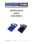
Mode d’emploi Joystick CHALLENGER Ji GECMA COMPONENTS GMBH MANUAL JI REV 1.6 FR.DOC WWW.GECMA.COM 31.01.07 TEL: +49 2237 6996-0 A.J. FAX: -99 1 Sommaire Sommaire.............................................................................................. 2 Introduction ........................................................................................... 2 Différents modèles du Challenger Ji...................................................... 2 Montage ............................................................................................... 3 Affectation des broches ........................................................................ 3 Données techniques ............................................................................. 4 Indications de sécurité .......................................................................... 5 Indications générales ............................................................................ 6 Introduction Le Challenger Joystick (Ji) est un joystick à sécurité intrinsèque qui peut être utilisé dans les zones 0 / zone 22. Le joystick fonctionne sans contact électrique, ce qui permet une marche pratiquement sans maintenance et sans usure. Il résulte de la technique sensorielle utilisée une résolution pratiquement infinie. En plus des boutons qui se trouvent sur la façade, un bouton peut être intégré sur le joystick ( par exemple : Ji-SW) . Ce bouton a la même fonction du botton gauche d’une souris. Il s'utilise pour la commande de ASD (Application Supporting Devices) par exemple de terminaux informatiques et est étudié pour une utilisation dans des zones à risque d’explosion. Pour le montage dans des composants Challenger, une console de visualisation Challenger FMO est nécessaire pour les options „2.PD“. Il dispose d’une interface de données PS/2 pour le raccord à une interface de données à sécurité intrinsèque. Le CHALLENGER Ji est compatible avec Microsoft™ ainsi qu’avec les pilotes d’installation standards des souris de Microsoft. Différents modèles du Challenger Ji Le Challenger Ji peut être livré en différents modèles : Ji Ji-B6 Ji-B12 Ji SW Ji-B6 SW Ji-B12 SW Joystick Joystick avec une barrière pour 6,25V max. Joystick avec une barrière pour 12,5V (max.) Joystick avec commutateur Joystick avec une barrière pour. 6.25V(max.) avec commutateur Joystick avec une barrière pour 12.5V(max.) avec commutateur MANUAL JI REV 1.6 FR.DOC 05.01.04 2 Montage De manière à assurer la protection IP66, le module Joystick doit être encastré dans un boîtier certifié au moins IP66 (avec une découpe de 153mm x 84mm bzw. 6“ x 3,3“). Le module Joystick est installé dans la découpe du boîtier avec le front vers l’extérieur et est calé de l’intérieur à l’aide d’au moins quatre crochets fixés à intervalles réguliers sur le périmètre extérieur du boîtier du joystick de manière à ce que le module soit bien stable. Le raccordement électrique est indiqué dans le plan de câblage n°10100470 et dans le document d’agrément. Affectation des broches broche K44-1 ou marron ou 1 K44-2 ou blanc ou 2 K44-3 ou jaune ou 3 K44-4 ou vert ou 4 Signification circuit d’alimentation + UB circuit d’alimentation / flux des données GND Data Clock La numération des bornes peut être consultée sur la plaque caractéristique située à proximité des bornes. De plus amples détails sont contenus dans le plan de câblage n° 10100470 et dans le document d'agrément. MANUAL JI REV 1.6 FR.DOC 05.01.04 3 Données techniques mode de protection : température de service : (de 10 à 90 % hum. rel., non conditionné) agrément : Zone 0 Zone 1 Zone 22 II 1 G EEx ia IIB T4 II 2 G EEx ia IIC T4 II 3 D T60°C IP6X Ex ia IIB T4 température extérieure: -20°C ... +60°C (-4°F à 140°F) TÜV 04 ATEX 2459 Ex ia IIC T4 température extérieure: -40°C ... +70°C (-40 °F à 158° F) TÜV 04 ATEX 2459 Ex T60°C IP6X Matière du boîtier : tôle/aluminium Dimensions du boîtier : voir plan Protection du boîtier : frontal IP66 avec montage adéquat. Ta: -25°C ... +60°C (-13°F to 140°F) TÜV 04 ATEX 2647X Raccord alimentation: Broche K44 2 x (0,5-2,5)mm² fixe / flexible ou conduite de raccordement raccord interface : Broche K44 2 x (0,5-2,5)mm² fixe / flexible ou conduite de raccordement températures de stockage : de -20 °C à +60°C (-4°F à 140°F), de 10 à 90% hum. rel. non cond. type Ji : tension d’alimentation : données par une unité d’alimentation à sécurité intrinsèque avec les techniques suivantes : Umax ≤ 5,5 V, Imin > 14 mA Cimax 19uF, Li négligeables type Ji-B6 : tension d’alimentation : données par une unité d’alimentation à sécurité intrinsèque avec les techniques suivantes : Umax ≤ 6,25 V, Imin > 14 mA Ci, Li négligeables type Ji-B12 : tension d’alimentation : données données techniques du techniques flux de données pour tous les types Ji : matière de la protection du levier de commande : charge admissible max. : par une unité d’alimentation à sécurité intrinsèque avec les techniques suivantes : Umax ≤ 12,5 V, Imin > 14 mA Ci, Li négligeables par une interface à sécurité intrinsèque avec les données suivantes : Uimax ≤ 5,5 V Uo ≤ 5,5V, Io ≤ 142mA, Po ≤ 105mW Ci, Li négligeables néoprène 300N Pour plus d’informations, consulter le document d’agrément. MANUAL JI REV 1.6 FR.DOC 05.01.04 4 Indications de sécurité Indications de sécurité générales Les indications contenues dans ce chapitre doivent être strictement respectées pour qu’une marche fiable et en sécurité puisse être garantie. Le document d’agrément et les conditions spéciales contenues sont également à respecter. Les règles nationales de sécurité et de prévention des accidents sont à respecter. L’installation ne doit être réalisée que par une personne qualifiée. Cette personne devra connaître les particularités des installations en zone à risques d’explosion. La garantie ne couvre pas les défaillances dues à une utilisation non conforme ou interdite et au nonrespect des indications contenues dans ce manuel d’utilisation. N’utiliser l’appareil que conformément au but fixé. Les modifications réalisées sur l’appareil ne sont pas autorisées. Seule la société Gecma Components GmbH est en droit d’ouvrir le boîtier. Montage Les règles nationales de montage et d’installation sont à respecter. Les règles techniques reconnues sont à respecter. Les moyens de production sont à installer et à exploiter conformément aux normes, directives et manuels d’installation. Le boîtier doit être mis à la terre grâce au dispositif prévu à cet effet. Le conducteur de mise à la terre doit avoir une section d'au moins 4mm². L’appareil ne doit être raccordé que hors tension. L’installation d’un faisceau de câbles à sécurité intrinsèque contenant les câbles d’alimentation et d’acheminement des signaux doit être réalisée de telle manière à ce que entre les circuits électriques aucune défaillance ne puisse se produire, voir IEC 60079-14, 12.2.2.8. Si le joystick utilisé en atmosphère poussiéreuse doit être changé, l’appareil ou le boîtier dans lequel le joystick est monté doit d’abord être mis hors tension et éventuellement refroidir conformément aux directives de sécurité. Avant d’ouvrit l’appareil ou le boîtier voire pendant que le boîtier est ouvert, veillez à ce que l’atmosphère environnant contiennent le moins de poussière que possible et à ce que la poussière n’entre pas dans le boîtier. Veillez également lors du montage d’autres composants à ce que tous les joints soient dans un bon état et que tout soit bien étanche. Avant de mettre l’appareil en service assurez vos d’avoir installer l’appareil conformément aux prescriptions et veillez à ce que ni l’appareil, ni les câbles ne soient endommagés. Si l’appareil n’est pas alimenté par un système à sécurité intrinsèque, il perd son agrément et ne peut plus être utilisé comme appareil à sécurité intrinsèque. Si l’appareil a été utilisé intrinsèquement avec un niveau de protection bas (par exemple ib), il ne doit pas être utilisé ensuite pour des applications à un niveau de protection supérieur (par exemple ia). Fonctionnement L’appareil ne doit être utilisé que intact et propre. En cas de défaillances pouvant entraîner une détérioration de la protection IP (fissures, trous ou composants défectueux) l’appareil doit immédiatement être mis hors service. Avant une remise en service, les composants défectueux doivent être changés. En cas de détérioration du joystick, ne plus le toucher car il existe un risque de blessure. Si l’appareil est utilisé dans une atmosphère poussiéreuse, les couches de poussière de >5mm doivent être enlevées. MANUAL JI REV 1.6 FR.DOC 05.01.04 5 En cas de non respect et d'infraction, la protection contre les explosions ne peut être assurée et les dommages entraînés ne seront pas couverts par la garantie. Les dérogations doivent recevoir l’autorisation préalable écrite de GeCma Components GmbH. Indications générales Avant de commencer le montage, veuillez lire entièrement le mode d'utilisation ! En cas de doute (en raison de fautes de traduction), le mode d’emploi allemand fait foi. Nous déclinons toute responsabilité pour les fautes d’impression et erreurs éventuellement contenues dans de mode d’emploi. Si vous avez des questions ou suggestions veuillez contacter : GeCma Components GmbH Heisenbergstraße 26 – 40 50169 Kerpen Allemagne Tél.: +49 (0)22 37 / 69 96 0 Fax: +49 (0)22 37 / 69 96 99 mailto:[email protected] http://www.gecma.com progrès technologique Le fabricant se réserve le droit d’adapter sans avertissement les données techniques aux progrès technologique. Réparations, substances dangereuses Il est impératif de joindre à tout appareil envoyé à GeCma Components GmbH pour réparation une description des défaillances. Les mesures suivantes doivent être prises avent d’envoyer un appareil pour réparation: Prenez soin d’éliminer tous les restes collants. Faites attention de supprimer les restes collants incrustés dans les joints et fentes. Nous vous demandons de renoncer à un envoi s’il ne vous est pas possible d’éliminer en toute sécurité intégralement les substances mettant en danger la santé. Les frais pour l’évacuation éventuelle des substances dangereuses et les dommages corporels (brûlures par acide, etc.) entraînés par un nettoyage insuffisant seront facturés au propriétaire de l'appareil. Marques de fabrique utilisées AT, IBM et PS/2, sont des marques enregistrées de la International Business Machines Corporation. Microsoft, Windows et Windows NT sont des marques enregistrées de la Microsoft Corporation. Toutes les marques de fabrique nommées ou reproduites dans le texte sont des marques de fabrique des propriétaires respectifs et sont reconnues comme enregistrées. MANUAL JI REV 1.6 FR.DOC 05.01.04 6 Translation Translation TÜV CERT (13) EC Design Test Certificate (1) (2) Devices and safety systems for use in accordance with regulations in areas at risk from explosion – guideline 94/9/EC (3) EC design test certificate number: (14) (15) Description of the equipment: Behind the front plate the electronic components are protected with a housing of at least IP 20. The protection from front is IP65. Is a higher enclosureprotection necessary the unit have to be mountet in a suitable hausing. (4) Device: Challenger Joystick Typ Ji (5) Manufacturer: Gecma Components GmbH (6) Address: (7) The construction of this device and the different permitted version are specified in the appendix to this design test certificate. (8) The TÜV NORD CERT GmbH & Co.KG, TÜV CERT certification agency, certifies - as appointed office no. 0032 in accordance with the guideline of the council of the European Community of 23rd March 1994 (94/9/EC) – the fulfilment of fundamental safety and health requirements for the design and manufacture of devices and safety systems for correct use in areas at risk from explosion, in accordance with Appendix II of the guideline. The results of the test are set out in the confidential test report no. 04 YEX 551344. The connection can be made via a premanufactured terminal strip or K44 connection. The maximum cablelength is 50m. Refer following text. In the frontplate can be mountet, beside the joysticklever, up to three buttons. Heisenbergstr. 26-40 D 50169 Kerpen The permitted ambient temperature range for each type can be found in the following table: Category 1 2 The basic safety and health requirements are met by conformity with EN 50014:1997 + A1 + A1 EN 50020:2002 EN 1127:1997 EN 50284:1999 (10) If there is an “X” sign behind the certification number, special conditions for the safe use of the device in the appendix to certificate are referred to. (11) This EC design test certificate only relates to the design and testing of the specified device in accordance with guideline 94/9/EC. Further requirements of these guidelines apply for the manufacturing and the bringing into circulation of this device. These requirements are not covered by this certificate. (12) The marking of the device must contain the following information: II 1 G EEx ia IIB T4 and II 2 G EEx ib IIC T4, resp. TÜV NORD CERT GmbH & Co. KG TÜV CERT certification body Am TÜV 1 D-30519 Hannover Phone: 0511 986-1470 Fax: 0511-986-2555 EC Type Test Certificate No. TÜV 04 ATEX 2459 The Challenger Joystick (Ji) is an intriniscally safe operating device, e.g. for controlling a pointer on a display. TÜV 04 ATEX 2459 (9) Annex Hannover, 15.04.2004 sd./- illegible The Head This certificate must only be circulated without any modification. Excerpts or changed require the approval of TÜV NORD CERT GmbH & Co. KG Ambient Temperature Range -20°C to 60°C -40°C to 70°C Electrical Data Type Ji Supply Current Circuit (Terminals K44-1 or cable brown or 1; K44-2 or cable white or 2) In explosion protection type intrinsically safety EEx ia IIC/IIB Only for connection to certified intrinsically safe circuits Ui = 5.5 V Uo = 5,5 V Io = Ii of datacircuit but 77mA Po= Pi of datacircuit but 105mW Characteristic curve: linear Ci = 19uF The effective internal inductance are negligibly small. Interface circuit (Data: Terminals K44-3 or cable yellow or 3 Clock: Terminal K44-4 or cable green or 4) In explosion protection type intrinsically safety EEx ia IIC/IIB Only for connection to certified intrinsically safe circuits Ui = 5.5 V Uo = 5,5 V Io = 142mA (dynamic) Io = Ii of supplycircuit but 50mA (static) each circuit Po = Pi of supplycircuit but 105mW Characteristic curve: linear Ci = 19uF The effective internal inductance are negligibly small. This certificate must only be circulated without any modification. Excerpts or changed require the approval of TÜV NORD CERT GmbH & Co. KG Page 1 of 3 Page 2 of 3 Translation Translation Annex to EC Type Test Certificate No. TÜV 03 ATEX 2459 First Supplement for TÜV CERT EC Design Test Certificate TÜV 04 ATEX 2459 Note the rules for connecting intrinsically safe circuits. The intrinsically safe circuits are galvanic together connected. Device: The Challenger Joystick Typ Ji are suitable for mount and connecting to the under DMT 00 ATEX E 089 X with 1. supplement, certificatet devices Challenger KB, KB-2*, KMU, KMU-2*, MTD, MTD-2* and under TÜV 03 ATEX 2251 certificatet devices KB-FPi and KB-2D-FPi instead of Challenger TB and Challenger M. Becouse of the protectionlevel and category of the in the top listed devices the protectionlevel of the intrinsically safe circuits are “ib” and category 2 of the complete equipment. The maximum permitted cablelength are 5m (16) The test documents are listed in test report no. 04 YEX 551344. (17) Particular requirement: None (18) Fundamental safety and health requirements: None in addition Challenger Joystick Typ Ji, Ji-B6 and Ji-B12 Manufacturer: Gecma Components GmbH Address: Heisenbergstr. 26-40 D 50169 Kerpen The Challenger Joystick type Ji will be expanded with the types Ji-B6 and Ji-B12 Additional the mechanical construction modified. Optional a button can be located to the joysticklever. Electrical Data When use in category 1 G the circuits must be protected by protectionlevel “ia”. Type Ji This certificate must only be circulated without any modification. Excerpts or changed require the approval of TÜV NORD CERT GmbH & Co. KG Supply Current Circuit (Terminals K44-1 or cable brown or 1; K44-2 or cable white or 2) In explosion protection type intrinsically safety EEx ia IIC/IIB Only for connection to certified intrinsically safe circuits Ui = 5.5 V Pi = 0,9 W Uo = 5,5 V Io = Ii of datacircuit but ≤ 77mA Po= Pi of datacircuit but ≤ 105mW Characteristic curve: linear Ci = 19uF The effective internal inductance are negligibly small. Interface circuit (Data: Terminals K44-3 or cable yellow or 3 Clock: Terminal K44-4 or cable green or 4) In explosion protection type intrinsically safety EEx ia IIC/IIB Only for connection to certified intrinsically safe circuits Ui = 5.5 V Uo = 5,5 V Io = Ii of supplycircuit but ≤ 77mA Po = Pi of supplycircuit but ≤ 105mW Characteristic curve: linear The effective internal capacitances and inductance are negligibly small. This certificate must only be circulated without any modification. Excerpts or changed require the approval of TÜV NORD CERT GmbH & Co. KG Page 3 of 3 Page 1 of 3 Translation Translation Annex to 1. supplement of EC Type Test Certificate No. TÜV 03 ATEX 2459 Interface circuit (Data: Terminals K44-3 or cable yellow or 3 Clock: Terminal K44-4 or cable green or 4) Type Ji-B6 Supply Current Circuit (Terminals K44-1 or cable brown or 1; K44-2 or cable white or 2) In explosion protection type intrinsically safety EEx ia IIC/IIB Only for connection to certified intrinsically safe circuits Ui = 6,25 V Uo = 5,5 V Io = 74 mA (short term) Io = 38 mA (static) Po= Pi of datacircuit but ≤ 53mW Characteristic curve: linear The effective internal capacitances and inductance are negligibly small. In explosion protection type intrinsically safety EEx ia IIC/IIB Only for connection to certified intrinsically safe circuits Ui = 5.5 V Uo = 12,5 V Io = 77 mA (short term) Io = Ii of supplycircuit but ≤ 21mA (static) Po = Pi of supplycircuit but ≤ 65mW Characteristic curve: linear The effective internal capacitances and inductance are negligibly small. Note the rules for connecting intrinsically safe circuits. The intrinsically safe circuits are galvanic together connected. Interface circuit (Data: Terminals K44-3 or cable yellow or 3 Clock: Terminal K44-4 or cable green or 4) In explosion protection type intrinsically safety EEx ia IIC/IIB Only for connection to certified intrinsically safe circuits Ui = 5.5 V Uo = 6,25 V Io = 77 mA (short term) Io = Ii of supplycircuit but ≤ 43mA (static) Po = Pi of supplycircuit but ≤ 67mW Characteristic curve: linear The effective internal capacitances and inductance are negligibly small. All other specifications valid without changes. The test documents are listed in test report no. 04 YEX 551344-d. TÜV NORD CERT GmbH & Co. KG TÜV CERT certification body Am TÜV 1 D-30519 Hannover Phone: 0511 986-1470 Fax: 0511-986-2555 Hannover, 24.01.2006 sd./- illegible The Head Type Ji-B6 Supply Current Circuit (Terminals K44-1 or cable brown or 1; K44-2 or cable white or 2) In explosion protection type intrinsically safety EEx ia IIC/IIB Only for connection to certified intrinsically safe circuits Ui = 12,5 V Uo = 5,5 V Io = 11 mA (short term) Io = 9 mA (static) Po= Pi of datacircuit but ≤ 15mW Characteristic curve: linear The effective internal capacitances and inductance are negligibly small. This certificate must only be circulated without any modification. Excerpts or changed require the approval of TÜV NORD CERT GmbH & Co. KG This certificate must only be circulated without any modification. Excerpts or changed require the approval of TÜV NORD CERT GmbH & Co. KG Page 2 of 3 Page 3 of 3 Translation TÜV CERT Declaration of conformity (1) (2) Devices and safety systems for use in accordance with regulations in areas at risk from explosion – guideline 94/9/EC (3) EC design test certificate number: TÜV 04 ATEX 2647 X (4) Device: Challenger Joystick Typ Ji, Ji-B6, Ji-B12 (5) Manufacturer: Gecma Components GmbH (6) Address: (7) The construction of this device and the different permitted version are specified in the appendix to this design test certificate. (8) The TÜV NORD CERT GmbH & Co.KG, TÜV CERT certification agency, certifies - as appointed office no. 0032 in accordance with the guideline of the council of the European Community of 23rd March 1994 (94/9/EC) – the fulfilment of fundamental safety and health requirements for the design and manufacture of devices and safety systems for correct use in areas at risk from explosion, in accordance with Appendix II of the guideline. The results of the test are set out in the confidential test report no. 04 YEX 551344b. (9) The basic safety and health requirements are met by conformity with Heisenbergstr. 26-40 D 50169 Kerpen EN 50281-1-1: 1998 +A1 :2002 (10) If there is an “X” sign behind the certification number, special conditions for the safe use of the device in the appendix to certificate are referred to. (11) This EC design test certificate only relates to the design and testing of the specified device in accordance with guideline 94/9/EC. Further requirements of these guidelines apply for the manufacturing and the bringing into circulation of this device. These requirements are not covered by this certificate. (12) The marking of the device must contain the following information: II 3 D T60°C IP 6X TÜV NORD CERT GmbH & Co. KG TÜV CERT certification body Am TÜV 1 D-30519 Hannover Phone: 0511 986-1470 Fax: 0511-986-2555 Hannover, 29.10.2004 sd./- illegible The Head This certificate must only be circulated without any modification. Excerpts or changed require the approval of TÜV NORD CERT GmbH & Co. KG Page 1 of 2 Translation (13) First Supplement for TÜV CERT Annex (14) (15) Translation EC Type Test Certificate No. TÜV 04 ATEX 2647 X EC Design Test Certificate TÜV 04 ATEX 2647 X Description of the equipment: The Challenger Joystick (Ji) is an intriniscally safe operating device, e.g. for controlling a pointer on a display. Device: The electrical connection realized with terminals or with a premounted cable, whereby the electrical connection normally realized inside the additional enclosure. Manufacturer: Gecma Components GmbH In the frontplate can be mountet, beside the joysticklever, up to three buttons. Address: The operationtemperature specified to -25°C up to 6 0°C. Challenger Joystick Typ Ji, Ji-B6 and Ji-B12 Heisenbergstr. 26-40 D 50169 Kerpen Electrical Data The Challenger Joystick type Ji, Ji-B6 and Ji-B12 will be produced regarding the new productiondirectives. Type Ji The mechanical construction modified. Optional a button can be located to the joysticklever. Supply Current Circuit (Terminals K44-1 or cable brown or 1; K44-2 or cable white or 2) To connect to circuits with follow max. values under normal conditions: All other specifications valid without changes. The test documents are listed in test report no. 04 YEX 551344-e. U = 5,5V for type Ji U = 6,25V for type Ji-B6 U= 12,5V for type Ji-B12 To connect to circuits with follow max. values Interface circuit (Data: Terminals K44-3 or cable yellow under normal conditions: or 3 Clock: Terminal K44-4 or cable green U = 5,5V or 4) TÜV NORD CERT GmbH & Co. KG TÜV CERT certification body Am TÜV 1 D-30519 Hannover Phone: 0511 986-1470 Fax: 0511-986-2555 (16) The test documents are listed in test report no. 04 YEX 551344b. (17) Particular requirement: The Challenger Joystick must be mounted into a enclosure which fulfill the requirements of category 3D EN 50281-1-1 as minimum. (18) Fundamental safety and health requirements: None in addition Hannover, 24.01.2006 sd./- illegible The Head This certificate must only be circulated without any modification. Excerpts or changed require the approval of TÜV NORD CERT GmbH & Co. KG This certificate must only be circulated without any modification. Excerpts or changed require the approval of TÜV NORD CERT GmbH & Co. KG Page 2 of 2 Page 1 of 1