1
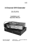
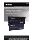
® ® NETWORK SERVICES NOVEMBER 2008 ACU5051A ACU5052A ServSwitch™ SRX USER GUIDE ER W PO S ES PN A AR SH B SRX BL K AC BO ER W PO K LIN L CA LO ON OU SRX TO X T K LIN TE MO ON RE TO ® E OT EM R ® 72 4-7 46 0 -55 0 BL AC KB OX ® O UT AL C LO IN B ® A 72 4 6 -74 -55 00 IN CUSTOMER SUPPORT INFORMATION Order toll-free in the U.S.: Call 877-877-BBOX (outside U.S. call 724-746-5500) FREE technical support 24 hours a day, 7 days a week: Call 724-746-5500 or fax 724-746-0746 Mailing address: Black Box Corporation, 1000 Park Drive, Lawrence, PA 15055-1018 Web site: www.blackbox.com • E-mail: [email protected] Contents Connections..................................................................................5 Mounting......................................................................................5 Connections at the local module............................................6 Local module power...........................................................7 Connections at the remote module........................................8 Dual user configuration........................................................10 Video display (DDC) information..........................................11 Video sharpness adjustment.................................................12 Getting assistance.......................................................................14 Troubleshooting.........................................................................14 Safety information.....................................................................15 Radio Frequency Energy............................................................16 Normas Oficiales Mexicanas (NOM) statement........................17 Instrucciones de seguridad...............................................17 BlackBox subsidiary contact details...........................................19 welcome Further information General use.................................................................................13 Dual user arbitration..................................................................13 Peripheral operation..................................................................13 installation Installation Introduction..................................................................................2 Supplied items..............................................................................3 Optional items..............................................................................4 operation Operation Welcome contents ® Welcome ® PC OUT BLACK BOX IN SRX BLACK BOX POWER CATx link cable(s) SRX POWER SHARPNESS OUT LINK ® ® 724-746-5500 Up to 50 metres separation REMOTE LINK TO REMOTE ® ® ON TO LOCAL ON 724-746-5500 operation LOCAL IN VIDEO 1 VIDEO 2 AUDIO RS232 SERIAL USB welcome The Wizard SRX extenders have been designed to be quick to install and totally transparent in operation. All connectors are industry standard and the video sharpness adjustments are made using a simple rotary dial. Where two screens are required, a dual VGA variant provides double video channels in addition to full support for an RS232 serial device. So whether you are extending your workplace or creating a costeffective distributed audio visual system, the Wizard SRX extenders provide the power and flexibility to create the right solution. installation Using the Wizard SRX extenders does not mean that you need to compromise on functionality in any way. Our highly efficient transmission methods mean that high video resolutions of up to 1920 x 1440 are supported together with CD quality digital sound that produces no crackles - even in the quietest interludes. The USB connections are seamless and thanks to our unique ‘Bi-tripos’ circuitry, four full speed USB 2.0 devices can be used simultaneously with full support for disconnect/re-connect at any time without causing errors. Thank you for choosing the ServSwitch Wizard SRX extenders which provide a very effective way to put distance between your computer and its peripherals. The compact casings and ease of use of the Wizard SRX modules belie the ingenuity of their operation. Using our proprietary transmission techniques we are able to reliably transfer more signals than ever before along a single length of Category 5, 5e or 6 twisted pair cabling. What this means for you is that your video, audio, USB keyboard, USB mouse and two other USB channels are all readily and reliably available at up to 50 metres away. contents Introduction USB device * Secondary video, RS232 serial and a second link cable are available only with the Wizard SRX Dual VGA variant USB device Serial device Supplied items ® Wizard SRX standard extender modules K BO LIN TO K RE TE MO ON X BL AC K BO SH T LO IN CA L 4 72 ® -74 6-5 P AR NE SS LIN TO K LO L CA ON X ® OU USB (A to B type) lead ER SRX ® 50 0 RE TE MO 4 72 ® -74 6-5 50 0 IN SRX remote module welcome SRX local module Video lead (15 way, male to male) Self adhesive feet Power adapter and country- specific power lead (for remote module) Audio lead (3.5mm jacks) Wizard SRX dual VGA variant extender modules W PO W PO BL AC K BO OU T SRX A B LIN TO K RE TE MO ON X BL AC K BO ER S ES PN A AR SH B K LIN L CA LO ON TO X ® OU T IN L A OC L ® IN 4 72 -7 -5 46 50 CD-ROM The Dual VGA variant package includes all of the above ancillary items plus: ER SRX ® 0 RE TE MO ® B 7 -7 24 46 -55 00 B A A SRX Dual VGA local module contents BL AC T installation W PO OU operation ER SRX Dual VGA remote module Video lead (15 way, male to male) RS232 serial lead (9 way male to female) W PO SRX Optional items ® welcome Rack mount chassis Rack mount plate for SRX dual VGA module (useable for the local or remote modules) operation installation Rack mount plate for SRX standard module (useable for the local or remote modules) contents Power adapter and country- specific power lead for local module (if USB powering not possible) Installation 1 2 34 contents welcome ON installation Important Do not attach a USB hub to the SRX remote, nor plug the SRX local module into another USB hub. To do so will reduce the maximum cable length over which the system will extend USB; also, some USB hubs may not provide enough power to operate the local unit. The SRX modules offer two main mounting methods: • Supplied four self-adhesive rubber feet • Rack mount brackets - see below operation Installation of the SRX modules is straightforward with minimal configuration requirements in most cases. • Connections at the local module • Connections at the remote module Mounting Connections ® BL Connections at the local module OU ® T IN LO CA L ® IN ® To local speakers contents AC 3 Optionally connect local speakers to the audio output connector on the local module. X OX 50 BL O KB KB 65 1 Where possible ensure that power is disconnected from the computer system to be connected. 2 Attach the video, USB (see the T OU Important note on page 5) and L CA IN LO (optionally) audio connections from the computer system to the relevant sockets on the IN local module. AC 0 OU T installation T L CA IN LO ® IN TO B W PO ER A T ON To secondary video output port OU TE MO K [Dual VGA variant only] Optionally attach a second video monitor to the upper video out socket on the local module. RE LIN To local monitor operation B A SRX [Dual VGA variant only] Optionally attach a second video input from the computer system to the upper video in socket on the local module. ER W PO OU K LIN TE MO ON RE To primary video output port TO To USB port 4 Optionally connect a local video monitor to the video out feedthrough connector on the local module. SRX Note: The dual VGA variant has its primary video, USB and audio connectors arranged in a similar manner to the single unit (shown above). welcome ® To speaker output port To secondary local monitor 65 50 0 ® SRX TO K LIN TE MO ON RE OU 6 [Dual VGA variant only] Optionally attach a serial connection lead to the female connector on the local module and attach the other end to a vacant serial port on your computer. ® OU T L CA IN LO ® IN B A T ER contents W PO 5 Attach the connector of the category 5, 5e or 6 link cable (up to 50 metres in length) to the ‘TO REMOTE’ socket on the local module (labelled ‘LINK 1’ on dual VGA variants). Local module power O In the majority of installations, the local module will derive all of its power successfully from the USB link with the computer system. However, if insufficient voltage is available from the computer system, the green indicator adjacent to the link connector will flash. If this occurs (or if you do not intend to use the USB connection with the computer) you will need to purchase and use a power supply identical to the one used for the remote module from your Black Box stockist. 1 If external power input is necessary, attach the output Low power indicator connector of the optional power supply to the ‘POWER’ socket of the local module. 2 Attach the IEC power lead to the power supply body and insert the mains plug of the lead to a nearby power outlet. R O E M N O T E L IN K 55 00 ® SRX TO RE LIN B OU W PO A T TE MO K ON [Dual VGA variant only] Attach the connector of a second category 5, 5e or 6 link cable (up to 50 metres in length) to the ‘LINK 2’ socket on the local module. welcome To computer serial port installation Link to remote module ER operation ® SRX TO K TE MO ON RE LIN OU T ER W PO Note: If a power adapter is plugged into the module but not switched on, it will prevent the unit from deriving power from the USB connection. Secondary link to remote module To optional power supply Connections at the remote module BL 1 Place the remote module adjacent to the user location. 2 Attach the lead from the video monitor to the video out socket on the remote module. BL AC KB OX TE MO RE KB ® OX 3 Attach the leads of up to four USB devices (two of which are usually a keyboard and mouse) to the sockets located adjacent to the video output connector. TE MO RE ® ® B A 4 [Dual VGA variant only] Optionally attach a serial device lead to the male serial connector on the remote module. To secondary video monitor To RS232 serial device TE MO installation [Dual VGA variant only] Optionally attach the lead from a second video monitor to the upper video out socket on the remote module. TE MO RE [MS2 variant only] Note: When connecting four USB devices to the unit, ensure that their total power requirements do not exceed 1700mA (1.7A). The USB standard states a maximum allowable current draw of 500mA (0.5A) per device, although most devices remain well below this limit - USB keyboards and mice typically require 100mA. Each X50 contains a selfresetting fuse that will prevent damage by shutting down the unit if the total power draw becomes excessive. RE ® B A operation To video monitor See the Important note on page 5 To USB devices, e.g. keyboard, mouse, etc. welcome contents ® AC 55 55 00 00 ® ® ® TO LO LIN K SH AR W PO PN ON CA L 7 Attach the output connector of the power supply to the ‘POWER’ socket of the remote module. SRX SRX TO K LIN L CA LO ON SH AR PN ES W PO ES S 5 Optionally attach the lead from your stereo speakers to the audio output socket on the remote module. S ER contents ER 55 To speakers 00 To power supply SRX 8 Attach the IEC power lead to the power supply body and insert the mains plug of the lead to a nearby power outlet. TO K LIN L CA LO ON SH AR W PO PN ES S ER Link to remote module installation welcome ® 6 Attach the connector of the category 5, 5e or 6 link cable (up to 50 metres in length) to the ‘TO LOCAL’ socket on the remote module (labelled ‘LINK 1’ on dual VGA variants). SRX TO K LIN L CA LO ON S ES PN A AR SH B ER W PO To mains outlet Secondary link to remote module operation ® [Dual VGA variant only] Attach the connector of a second category 5, 5e or 6 link cable (up to 50 metres in length) to the ‘LINK 2’ socket on the remote module. Dual user configuration ® You can combine two Wizard SRX extender sets to create a dual user configuration. Such an installation would allow a single computer to be controlled from two different positions, with each position receiving the same audio visual output and having equal and concurrent control over the computer. Arbitration between the two positions is handled by the computer’s USB system and so this arrangement is better suited to situations where two users would not often require simultaneous access. SRX BLACK BOX POWER SHARPNESS ER W PO O UT OU SRX BL AC KB OX T K LIN TO TE MO RE ON L CA IN LO ® ® IN AL USER 1 OC 7 ® -7 24 46 -55 00 contents First local module ON 724-746-5500 PC Audio, USB and video from the PC CATx link (up to 50m) OU OUT SRX BLACK BOX VIDEO AUDIO USB IN LOCAL LINK TO REMOTE ® ON 724-746-5500 Video and audio crosslinks are made from first local module to the second local module OUT SRX BLACK BOX KB Video crosslink from first to second local module OX T L CA LO ® IN IN AC IN POWER OUT ® BL Audio crosslink from first to second local module IN installation LINK TO LOCAL ® ® welcome REMOTE POWER LINK IN TO REMOTE ® ® ON 724-746-5500 CATx link (up to 50m) Both local modules require their own USB links to the PC BLACK BOX SRX POWER SHARPNESS REMOTE LINK ® ® 724-746-5500 TO LOCAL ON USER 2 Second USB from the PC Most of the connections are similar to the standard configuration. The main difference is in the links to the second local module. Use an audio link lead to connect the audio out socket of the first local module to the audio in socket of the second. Similarly, use a video link lead to connect the video out and video in ports. The second local module then requires its own USB link directly to the computer. In all other respects follow the standard instructions to connect CATx links and all of the remote module connections. operation OUT LOCAL 10 Video display (DDC) information O R E M N O T E When power is first applied to the local module (either from the computer’s USB port or an optional power adapter) it will search for valid DDC data on its video out connector. During this process, the yellow indicator (built into the link connector) will flash to indicate its progress: • If no valid DDC information is located, the yellow indicator will give one very short flash, representing an attempt to read data. No changes will be made to the information already stored within the local module. • If the DDC information is the same as that already stored, no change will be made and the yellow indicator will give one single flash as the information is checked and normal operation resumes. • If different DDC information is located, the yellow indicator will flash rapidly for 2 to 3 seconds while the new information is stored. A single flash will then be given as the information is checked and normal operation resumes. The local module’s yellow indicator also provides fault indications to assist with troubleshooting: • Two flashes - Checksum error prior to copying - no information will be programmed. • Three flashes - Too much data to fit into the module - the module can hold a maximum of two pages of DDC information. • Rapid flashing followed by four flashes - data was lost during copying - the default data was substituted. Repeat the power on process. • Rapid flashing followed by five flashes - Checksum error during copying - the default data was substituted. Repeat the power on process. L IN operation installation welcome contents K DDC indications O The Display Data Channel (or DDC) is an industry standard scheme which allows video monitors to declare their capabilities to the computer’s video adapter circuitry, allowing the latter to optimise their outputs accordingly. Since the widespread adoption of the scheme, video adapters have become increasingly dependent on receiving relevant DDC information during startup, before they will output anything more than a rudimentary video signal. It is not possible to transmit DDC data back from the video monitor that is attached to the remote module to the computer’s video adapter. Therefore, during startup of the local module, it will search for a video monitor connected to its local feed-through connector: • If a local video monitor is found, its DDC information will be compared to the information already stored and, if different, will be copied, stored and presented to the video adapter upon request. • If no local video monitor is found, the local module will make available its previously stored set of DDC parameters to the video adapter upon request; or, if none were stored, a default set. In either case, the DDC information taken by the video adapter will be used to determine the video output that is sent via the SRX modules to the remote monitor. If you find that the default DDC information is not completely suitable for your remote monitor, try temporarily connecting your remote monitor to the video out port of the local module. When the local module is powered up, it will read and store the DDC information from your monitor. You can then return the monitor to its remote position and the new DDC information will be used at every power on. ® 11 Video sharpness adjustment ® The Wizard SRX remote module includes a straightforward video adjustment to control picture sharpness on the remote monitor. 55 00 Black or bright white shadow on the right indicates the need for sharpness adjustment welcome High contrast black character on white background installation SRX TO K LIN L CA LO S ES PN AR SH ER W PO ® SRX W PO S ES PN A AR SH B operation ER Sharpness control for the first (A) video channel ON TO K LIN L CA LO ON The remote module for the dual VGA variant includes two separate sharpness adjustments for each video channel (the upper dial corresponds to the upper video output socket). Sharpness control for the second (B) video channel To display a suitable high contrast image The best way to clearly view the effect of sharpness and brightness adjustments is to display a high contrast image, with vertical edges, on the screen. • Open a word processor, type the capital letter ‘H’, or ‘M’ and increase the point size to 72 or higher. For best results, the background should be white and the character should be black. contents ® To adjust video sharpness 1 On the computer, display a suitable high contrast image (see right). 2 Insert a small flat-bladed screwdriver into the SHARPNESS adjustment hole so that it engages with the slot in the rotary dial. 3 Turn the rotary dial fully clockwise - you should see a bright white shadow to the right of your high contrast image: 4 Turn the rotary dial anticlockwise until the white shadow disappears and the edges of your image become sharp. 12 Operation RS232 serial The dual VGA variant modules provide additional support for an RS232 device. The 9 way male D-type socket on the remote module supports speeds up to 115,200 baud and all PC-AT flow control pins are supported. contents welcome When using two sets of SRX modules to allow two users to access a single computer, be aware that arbitration between the users is handled by the USB sub-system of the computer. Unlike with other Black Box products, this means that both users can control the computer at exactly the same time and the resulting keyboard and mouse influences will be an amalgam of the two inputs - i.e. a mouse move to the right by one user will cancel out a simultaneous left mouse move by the other. The same is also true when the local module has feed-through peripherals attached to it, adjacent to the computer. For this reason, the SRX dual user arrangement is better suited to situations where two users would not often require simultaneous access. Each SRX remote module provides four USB outlets, each of which can support USB 2.0 peripherals at speeds up to 12Mbps. The SRX appears to the computer as a four-port USB hub. If the link between the modules is interrupted, any connected USB peripherals will be automatically disabled and re-enabled once the connection is restored. [MS2 variant only] Note: When connecting four USB devices to the unit, ensure that their total power requirements do not exceed 1700mA (1.7A). The USB standard states a maximum allowable current draw of 500mA (0.5A) per device, although most devices remain well below this limit - USB keyboards and mice typically require 100mA. Each X50 contains a self-resetting fuse that will prevent damage by shutting down the unit if the total power draw becomes excessive. installation Dual user arbitration USB operation In use, the SRX modules should be transparent - the system and its peripherals should operate exactly as normal, the only difference being that they are now up to 50 metres apart. In some installations, you may see some ‘shadows’ to the right of high contrast screen characters. This can be caused by an incorrectly selected sharpness setting and it may be necessary to make adjustments to correct this. Please see Video sharpness adjustment in the ‘Installation’ section. Peripheral operation General use ® 13 Further information ® in the UK: [email protected] • Phone in the US: in the UK: 724-746-5500 +44 (0)118 965 6000 During startup (of the local module) • One very short yellow flash: no valid DDC information available from a locally connected video monitor, no changes made to stored DDC information. • Single yellow flash: DDC information being read from a locally connected video monitor, but no changes made to stored DDC information. • Rapid yellow flash for 2 to 3 seconds, followed by single flash: New DDC information being read and stored from a locally connected video monitor. • Two yellow flashes - Checksum error prior to copying - no information will be programmed. • Three yellow flashes - Too much data to fit into the module - the module can hold a maximum of two pages of DDC information. • Rapid yellow flashing followed by four flashes - data was lost during copying - the default data was substituted. Repeat the power on process. • Rapid yellow flashing followed by five flashes - Checksum error during copying - the default data was substituted. Repeat the power on process. During operation (either module) • Continual yellow: Valid CATx link to other module sensed. • Continual green: Correct power input sensed. • Green flashes: Power input too low for normal operation. In the case of the local module, this may be because the USB connection is unable to provide sufficient power. In these cases, an external power supply should be used with the local module. Important Do not attach a USB hub to the SRX remote, nor plug the SRX local module into another USB hub. To do so will reduce the maximum cable length over which the system will extend USB; also, some USB hubs may not provide enough power to operate the local unit. welcome [email protected] installation in the US: operation •Email Status indicators The green and yellow indicators built into the link connectors on each module provide useful feedback regarding the connection and power status: further information If you are still experiencing problems after checking the list of solutions in the Troubleshooting section then we provide a number of other solutions: contents Troubleshooting Getting assistance 14 Safety information contents welcome installation operation further information • For use in dry, oil free indoor environments only. • Do not use to link between buildings. • Ensure that all twisted pair interconnect cables are installed in compliance with all applicable wiring regulations. • Do not connect CATx link interfaces (RJ45 style connectors) to any other equipment, particularly network or telecommunications equipment. • Warning – the power adapter contains live parts. • No user serviceable parts are contained within the power adapter - do not dismantle. • Plug the power adapter into a socket outlet close to the module that it is powering. • Replace the power adapter with a manufacturer approved type only. • Do not use the power adapter if the power adapter case becomes damaged, cracked or broken or if you suspect that it is not operating properly. • If you use a power extension cord with the remote module, make sure the total ampere rating of the devices plugged into the extension cord do not exceed the cord’s ampere rating. Also, make sure that the total ampere rating of all the devices plugged into the wall outlet does not exceed the wall outlet’s ampere rating. • Do not attempt to service the modules yourself. • The power supply can get warm in operation – do not situate it in an enclosed space without any ventilation. ® 15 Radio Frequency Energy Canadian Department of Communications RFI statement This equipment does not exceed the class A limits for radio noise emissions from digital apparatus set out in the radio interference regulations of the Canadian Department of Communications. Le présent appareil numérique n’émet pas de bruits radioélectriques dépassant les limites applicables aux appareils numériques de la classe A prescrites dans le règlement sur le brouillage radioélectriques publié par le ministère des Communications du Canada. welcome This equipment generates, uses and can radiate radio frequency energy and if not installed and used properly, that is, in strict accordance with the manufacturer’s instructions, may cause interference to radio communication. It has been tested and found to comply with the limits for a class A computing device in accordance with the specifications in Subpart J of part 15 of FCC rules, which are designed to provide reasonable protection against such interference when the equipment is operated in a commercial environment. Operation of this equipment in a residential area may cause interference, in which case the user at his own expense will be required to take whatever measures may be necessary to correct the interference. Changes or modifications not expressly approved by the manufacturer could void the user’s authority to operate the equipment. installation This equipment has been tested and found to comply with the limits for a class A computing device in accordance with the specifications in the European standard EN55022. These limits are designed to provide reasonable protection against harmful interference. This equipment generates, uses and can radiate radio frequency energy and if not installed and used in accordance with the instructions may cause harmful interference to radio or television reception. However, there is no guarantee that harmful interference will not occur in a particular installation. If this equipment does cause interference to radio or television reception, which can be determined by turning the equipment on and off, the user is encouraged to correct the interference with one or more of the following measures: (a) Reorient or relocate the receiving antenna. (b) Increase the separation between the equipment and the receiver. (c) Connect the equipment to an outlet on a circuit different from that to which the receiver is connected. (d) Consult the supplier or an experienced radio/TV technician for help. FCC Compliance Statement (United States) operation European EMC directive 89/336/EEC further information A Category 5 (or better) twisted pair cable must be used to connect the units in order to maintain compliance with radio frequency energy emission regulations and ensure a suitably high level of immunity to electromagnetic disturbances. All other interface cables used with this equipment must be shielded in order to maintain compliance with radio frequency energy emission regulations and ensure a suitably high level of immunity to electromagnetic disturbances. contents ® 16 Normas Oficiales Mexicanas (NOM) electrical safety statement contents welcome installation 15En caso de existir, una antena externa deberá ser localizada lejos de las lineas de energia. 16El cable de corriente deberá ser desconectado del cuando el equipo no sea usado por un largo periodo de tiempo. 17Cuidado debe ser tomado de tal manera que objectos liquidos no sean derramados sobre la cubierta u orificios de ventilación. 18Servicio por personal calificado deberá ser provisto cuando: A: El cable de poder o el contacto ha sido dañado; u B: Objectos han caído o líquido ha sido derramado dentro del aparato; o C: El aparato ha sido expuesto a la lluvia; o D: El aparato parece no operar normalmente o muestra un cambio en su desempeño; o E: El aparato ha sido tirado o su cubierta ha sido dañada. operation 1 Todas las instrucciones de seguridad y operación deberán ser leídas antes de que el aparato eléctrico sea operado. 2 Las instrucciones de seguridad y operación deberán ser guardadas para referencia futura. 3 Todas las advertencias en el aparato eléctrico y en sus instrucciones de operación deben ser respetadas. 4 Todas las instrucciones de operación y uso deben ser seguidas. 5 El aparato eléctrico no deberá ser usado cerca del agua—por ejemplo, cerca de la tina de baño, lavabo, sótano mojado o cerca de una alberca, etc. 6 El aparato eléctrico debe ser usado únicamente con carritos o pedestales que sean recomendados por el fabricante. 7 El aparato eléctrico debe ser montado a la pared o al techo sólo como sea recomendado por el fabricante. 8 Servicio—El usuario no debe intentar dar servicio al equipo eléctrico más allá a lo descrito en las instrucciones de operación. Todo otro servicio deberá ser referido a personal de servicio calificado. 9 El aparato eléctrico debe ser situado de tal manera que su posición no interfiera su uso. La colocación del aparato eléctrico sobre una cama, sofá, alfombra o superficie similar puede bloquea la ventilación, no se debe colocar en libreros o gabinetes que impidan el flujo de aire por los orificios de ventilación. 10El equipo eléctrico deber ser situado fuera del alcance de fuentes de calor como radiadores, registros de calor, estufas u otros aparatos (incluyendo amplificadores) que producen calor. 11El aparato eléctrico deberá ser connectado a una fuente de poder sólo del tipo descrito en el instructivo de operación, o como se indique en el aparato. 12Precaución debe ser tomada de tal manera que la tierra fisica y la polarización del equipo no sea eliminada. 13Los cables de la fuente de poder deben ser guiados de tal manera que no sean pisados ni pellizcados por objetos colocados sobre o contra ellos, poniendo particular atención a los contactos y receptáculos donde salen del aparato. 14El equipo eléctrico debe ser limpiado únicamente de acuerdo a las recomendaciones del fabricante. further information Instrucciones de seguridad ® 17 installation further information Black Box Corporation, 1000 Park Drive, Lawrence, PA 15055-1018, United States of America Tel: +1-724-746-5500 Fax: +1-724-746-0746 operation © 2008 Black Box Corporation All trademarks are acknowledged. welcome contents ® Documentation by: www.ctxd.com 18 BlackBox subsidiary contact details United States www.blackbox.com 724-746-5500 724-746-0746 Austria www.black-box.at [email protected] +43 1 256 98 56 +43 1 256 98 56 Belgium www.blackbox.be [email protected] [email protected] [email protected] +32 2 725 85 50 +32 2 725 92 12 Denmark www.blackbox.dk [email protected] +45 56 63 30 10 +45 56 65 08 05 Finland www.blackbox.fi [email protected] +35 201 888 800 +35 201 888 808 France www.blackbox.fr [email protected] +33 1 45 606 717 +33 1 45 606 747 Germany www.black-box.de [email protected] +49 811 5541 110 +49 811 5541 499 Italy www.blackbox.it [email protected] +39 02 27 404 700 +39 02 27 400 219 Netherlands www.blackbox.nl [email protected] +31 30 241 7799 +31 30 241 4746 Norway www.blackboxnorge.no [email protected] +47 55 300 710 +47 55 300 701 Spain www.blackbox.es [email protected] +34 9162590732 +34 916239784 Sweden www.blackboxab.se [email protected] +46 8 44 55 890 +46 08 38 04 30 Switzerland www.black-box.ch [email protected] +41 55 451 70 71 +41 55 451 70 75 UK www.blackbox.co.uk [email protected] +44 118 965 6000 +44 118 965 6001 Ireland www.blackbox.co.uk [email protected] +353 1 662 2466 +353 1 662 2477 welcome Fax installation Phone operation Web Site/Email further information Country contents ® 19