1
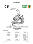
CR Owner’s Manual
BILLY GOAT CR550HC POWER RAKE
Owner's Manual
Accessories
Replacement Parts
SLICING REEL
SLICING BLADES
A complete vertislicing reel for your
CR. 20" wide reel for
use in grasses that
require vertical
cutting, and for
assisting in lawn
overseeding projects.
A full set of twenty
blades for
replacement. Includes
40 new capscrews,
and lock nuts for
replacement
installation.
SPACER
BUMPERS
DRIVE
BELT
A complete
replacement set.
44 of 1/2" spacer
bumpers and 4
of 1/4" spacer
bumpers
Original
Equipment drive
belt for your CR.
P/N 350252
P/N 350187
P/N 350258
P/N 350207
Part No 350245
1
FLAIL
BLADES
A complete
replacement set.
52 of our high
quality flail
blades for your
CR. Includes 8
new lock clips for
replacement
installation.
P/N 350251
FLAIL SHAFTS
A full set of four
shafts for
replacement.
Includes 8 new lock
clips for
replacement
installation.
Note: We
recommend
replacing the shafts
when you replace
flails.
P/N 350185
Form No F062206A
CR Owner’s Manual
ABOUT THIS MANUAL
®
THANK YOU for purchasing a BILLY GOAT CR Power Rake. Your new machine has been carefully designed and
manufactured to provide years of reliable and productive service. This manual provides complete operating and
maintenance instructions that will help to maintain your machine in top running order. Read this manual carefully
before assembling, operating, or servicing your equipment.
CONTENTS
SERIAL PLATE DATA AND SPECIFICATIONS
GENERAL SAFETY
3
4-5
SOUND AND VIBRATION
6
INSTRUCTION LABELS
7
PACKING CHECKLIST & ASSEMBLY
8
OPERATION
9-10
MAINTENANCE
11
TROUBLESHOOTING AND WARRANTY PROCEDURE
12
ILLUSTRATED PARTS & PARTS LISTS
Part No 350245
13-16
2
Form No F062206A
CR Owner’s Manual
SERIAL PLATE DATA
Record the model number, serial number, date of
purchase, and where purchased.
Purchase Date:
Purchased From:
Specifications
CR550HC
Engine: HP
5.0 (3.73 kW)
Engine: Model
GC160AQHA
Engine: Type
HONDA OHC
Engine: Fuel Capacity
2.1 qt (2.0 L)
Engine: Oil Capacity
0.63 qt. (0.6 L)
Total Unit Weight:
125# (56.8 kg)
20o
Max. operating slope
Lwa at operator position
99 dB(a)
Lpa at operator position
81 dB(a)
1.01g (9.94 m/s2)
Vibration at operator position
Part No 350245
3
Form No F062206A
CR Owner’s Manual
GENERAL SAFETY INSTRUCTIONS and SYMBOLS
The safety symbols shown below are used throughout this manual. You should become familiar with them before
assembling, operating, or servicing this equipment.
This symbol indicates important information that will prevent injury to yourself or others.
This symbol indicates ear protection is recommended when operating this equipment.
This symbol indicates eye protection is recommended when operating this equipment.
This symbol indicates gloves should be worn when servicing this equipment.
This symbol indicates that this manual and the engine manufacturer’s manual should be read
carefully before assembling, operation, or servicing this equipment.
This symbol indicates important information that will prevent damage to your BILLY GOAT
CR Power Rake.
®
This symbol indicates the engine oil level should be checked before operating this
equipment.
Read and make sure you thoroughly understand the following safety precautions before assembling, operating or
servicing this equipment:
READ this manual and the engine manufacturer’s manual carefully before assembling,
operating, or servicing this equipment.
EAR PROTECTION is recommended when operating this equipment.
EYE PROTECTION is recommended when operating this equipment.
BREATHING PROTECTION is recommended when operating this equipment.
EXHAUST from this product contains chemicals known to the State of California to cause
cancer, birth defects or other reproductive harm.
DO NOT operate this equipment on any unimproved forested, brushy, or grass covered land
unless a spark arrester is installed on the muffler as required by Section 4442 of the
California Public Resources Code. The arrester must be maintained in good working order.
Other states may have similar laws. Federal laws apply on federal lands.
DO NOT run engine in an enclosed area. Exhaust gases contain carbon monoxide, an
odorless and possibly fatal poison.
Part No 350245
4
Form No F062206A
CR Owner’s Manual
DO NOT run this equipment indoors or in any poorly ventilated area. Refueling outdoors is
recommended.
DO NOT refuel this equipment while the engine is running. Allow engine to cool for at least two
minutes before refueling.
DO NOT store gasoline near an open flame.
DO NOT remove gas cap while engine is running.
DO NOT start or operate engine if strong odor of gasoline is present.
DO NOT start or operate engine if gasoline is spilled. Move equipment away from spill until
gasoline has completely evaporated.
DO NOT smoke while filling the fuel tank.
DO NOT check for spark with spark plug or spark plug wire removed. Use an approved spark
tester.
DO NOT operate engine without a muffler. Inspect muffler periodically and replace if necessary.
If equipped with muffler deflector, inspect deflector periodically and replace if necessary.
DO NOT operate engine with grass, leaves or other combustible material near the muffler.
DO NOT touch muffler, cylinder, or cooling fins when hot. Contact with hot surfaces may cause
severe burns.
DO NOT leave equipment unattended while in operation.
DO NOT park equipment on a steep grade or slope.
DO NOT operate equipment with bystanders in or near the work area.
DO NOT allow children to operate this equipment.
DO NOT operate equipment with guards removed.
DO NOT operate equipment near hot or burning debris or any toxic or explosive materials.
DO NOT operate equipment on slopes greater than specified in Specifications section of this
manual.
DO NOT start engine without height adjust lever in up position and clutch bail disengaged.
DO NOT place hands or feet underneath unit, or near any moving parts.
ALWAYS remove spark plug wire when servicing equipment to prevent accidental starting.
ALWAYS check fuel lines and fittings frequently for cracks or leaks. Replace if necessary.
ALWAYS keep hands and feet away from moving or rotating parts.
ALWAYS store fuel in approved safety containers.
WARNING: Important
Remove all rocks, wire, string, etc. that can present a hazard during work prior to starting.
DO identify and mark all fixed objects to be avoided during work such as sprinkler heads, water
valves, buried cables, or clothes line anchors, etc.
Part No 350245
5
Form No F062206A
CR Owner’s Manual
SOUND
SOUND LEVEL 81 dB(a) at Operator Position
Sound tests were conducted in accordance with 2000/14/EEC, and were performed on 2-9-2002 under the
conditions listed below.
Sound power level listed is the highest value for any model covered in this manual. Please refer to serial plate on
the unit for the sound power level for your model.
General Conditions:
Temperature:
Wind Speed:
Wind Direction:
Humidity:
Barometric Pressure:
Sunny
o
o
43 F (6.1 C)
10 mph (16.1 kmh)
North West
82.2%
29.72Hg (754 mm Hg)
VIBRATION DATA
2
VIBRATION LEVEL 1.01g (9.94m/s )
Vibration levels at the operator’s handles were measured in the vertical, lateral and longitudinal directions using
calibrated vibration test equipment. Tests were performed on 5-25-2006 under the conditions listed below.
General Conditions:
Temperature:
Wind Speed:
Wind Direction:
Humidity:
Barometric Pressure:
Sunny
o
o
72.32 F (22.4 C)
3.8 mph (6.12kph)
East
62.2%
29.9Hg (101.3kpa)
INTENDED USE
INTENDED USE: This machine is designed for removing thatch from your lawn, renovation of existing lawns, and to
assist in overseeding operations. The machine should not be used for any other purpose than that stated above.
Do not operate if excessive vibration occurs. If excessive vibration occurs, shut engine off immediately and check
for damaged or worn reel, loose pulley bolts or set screws, loose engine or lodged foreign objects. (See trouble
shooting section on page 12).
Part No 350245
6
Form No F062206A
CR Owner’s Manual
INSTRUCTION LABELS
The labels shown below were installed on your BILLY GOAT ® CR Power Rake. If any labels are damaged or missing, replace them before
operating this equipment. Item numbers from the Illustrated Parts List and part numbers are provided for convenience in ordering replacement
labels. The correct position for each label may be determined by referring to the Figure and Item numbers shown.
LABEL DANGER KEEP HANDS
AND FEET AWAY
ITEM #51 P/N 400424
LABEL CAUTION GUARD
ITEM #52 P/N 900327
LABEL CLUTCH ITEM #49
P/N 830503
LABEL EXPLOSIVE FUEL
ITEM # 50 P/N 400268
DANGER FLYING DEBRIS
ITEM # 48 P/N 810736
LABEL INSTRUCTION HEIGHT ADJ.
ITEM #35 P/N 350224
ENGINE LABELS/CONTROLS
HONDA
Part No 350245
7
Form No F062206A
CR Owner’s Manual
PACKING CHECKLIST
Your Billy Goat Power Rake is shipped from the factory in one carton, completely assembled.
READ all safety instructions before assembling unit.
TAKE CAUTION when removing the unit from the box the Handle Assembly is attached and
folded over
PUT OIL IN ENGINE BEFORE STARTING
PARTS BAG &
LITERATURE ASSY
Warranty card P/N- 400972, Owner’s Manual P/N-350245, Declaration of Conformity P/N-350139, and
Literature CR Accessories 350246.
Boxing Parts
Checklist
26
28
Honda GC 5.0
OHC
Literature Assy
P/N-350243
28
ASSEMBLY
1. ASSEMBLE the left rear wheel to the axle using ¾” wrench.
2. UNFOLD the upper handle (item 26) and slide handle lock loops (item 28) into place to secure the upper handle
to the lower.
3. CHECK engine oil level and fill to proper level with engine manufacturers recommended grade of oil. Move
height adjust lever to down position, to level engine during checking. See engine manufacturers instruction
manual.
4. CONNECT spark plug wire.
Part No 350245
8
Form No F062206A
CR Owner’s Manual
OPERATION
Like all mechanical tools, reasonable care must be used when operating machine.
Inspect machine work area and machine before operating. Make sure that all operators of this
equipment are trained in general machine use and safety.
PUT OIL IN ENGINE BEFORE STARTING
STARTING
ENGINE: See engine manufacturer’s instructions for type and amount of oil and gasoline used. Engine must be
level when checking and filling oil and gasoline.
FUEL VALVE: Move fuel valve to "ON" position (when provided on engine).
STOP SWITCH: Located on the engine. "slow/stop" position.
CHOKE: Operated with choke lever on side of engine.
THROTTLE: Controlled by throttle lever on the motor.
IF YOUR UNIT FAILS TO START:
See Troubleshooting on page 12.
FOLDING HANDLE
This unit is equipped with a folding upper handle for easier storage and transportation. The handle can be folded by
sliding the handle lock loops (item 28) up. This releases the upper handle, allowing it to be folded over the unit.
HANDLING & TRANSPORTING:
This unit requires two people to lift it. With the handle in the folded position, lift holding the lower handle and
belt/shaft guard one on each side of the machine. Secure the machine in place during transport. See page 3 for
weight specifications
Never lift the machine while the engine is running.
BLADE POSITION & DEPTH CONTROL LEVER
The blades can be raised or lowered into the ground by height adjustment
lever on the engine base. The resulting blade depth can be adjusted higher
or lower. See ADJUSTING BLADE DEPTH.
ADJUSTING BLADE DEPTH
The depth of the blades can be raised or lowered by rotating the knob on
the top of the adjustment lever. The blades are lowered by rotating the
knob counter-clockwise, and raised by rotating the knob clockwise. The
relative depth of the blades can be gauged by using the depth scale
located on the right front corner of the engine base.
Part No 350245
9
Form No F062206A
CR Owner’s Manual
RAKING OPERATION
MOW: Mow the lawn to it's normal cut height
DRY: Be sure grass is dry. Wet conditions can cause increased damage to healthy grass.
SET DEPTH: With engine off, set the raking depth so that the blades just touch on a flat surface (i.e. driveway, or
sidewalk).
START ENGINE: See page 9.
ENGAGE BLADES: Pull back on the bail on the operators handle. NOTE: When engaging the blades in heavy load
conditions (i.e. heavy thatch, or very uneven turf), push down on the operators handle lifting the front wheels slightly.
Engage the blades. Slowly lower the unit into the turf.
RAKE: Rake a small test area and examine the results. Thatch should be removed and deposited on top of the healthy
grass. If excessive damage occurs to healthy grass, adjust the blade depth to decrease damage. Continue raking the
yard, working in one direction (i.e. north-south, or east-west). NOTE: If a large drop in engine RPM occurs, or the unit
pulls you forward and bounces during operation the blade depth is set too low.
REMOVE THATCH: After raking, a layer of thatch will be deposited over the top of the lawn. This thatch must be
removed prior to any fertilizing, seeding, or watering of the lawn. We suggest the use of a lawn vacuum or wheeled
blower for collection and removal of the thatch.
VERTI-CUTTING OPERATION
MOW: Mow the lawn to it's normal cut height
DRY: Be sure grass is dry. Wet conditions can cause increased damage to healthy grass.
SET DEPTH: With engine off, set the raking depth so that the blades just touch on a flat surface (i.e. driveway, or
sidewalk).
START ENGINE: See Page 9.
ENGAGE BLADES: Pull back on the bail on the operators handle. NOTE: When engaging the blades in heavy load
conditions (i.e. heavy thatch, or very uneven turf), push down on the operators handle lifting the front wheels slightly.
Engage the blades. Slowly lower the unit into the turf.
SLICE: Verti-cut a small test area and examine the results. Some thatch and cut stems should be removed and
deposited on top of the healthy grass. Grass runners should be cut and ready for removal. If excessive damage occurs
to healthy grass, adjust the blade depth to decrease damage. Continue raking the yard, working in one direction (i.e.
north-south, or east-west). NOTE: If a large drop in engine RPM occurs, or the unit pulls you forward and bounces
during operation the blade depth is set too low.
REMOVE THATCH/STEMS: After verti-cutting, a layer of thatch and cut stems will be deposited over the top of the
lawn. We suggest the use of a lawn vacuum or wheeled blower for collection and removal of the thatch/stems.
RAKING/SLICING TIPS
THATCH: Thatch is a dense layer of dead grass, clippings, and roots that builds up over time at the base of the lawn
preventing air, water, and fertilizer from reaching the soil. This can cause shallow root development and make a lawn
more susceptible to drought and disease. Thatch also provides an ideal environment for insects to hide and multiply.
Periodic removal of thatch will keep your lawn in good health.
HEAVY THATCH: Lawns with an excessive amount of thatch will require multiple treatments for effective removal.
Trying to remove excessive thatch (greater than 3/4"[19 mm] deep) in one treatment will damage or destroy the living
part of the lawn. It is best to remove heavy thatch in seasonal treatments (i.e. spring, and fall).
CHECK: Before beginning, it is best to evaluate the condition of the lawn by cutting one or more core samples from
area to be treated. A core can be cut using a piece of pvc, or metal pipe. Hammer the pipe into the ground, remove it,
push the core out of the pipe and inspect it to determine the depth of thatch in your yard.
SLOPES: Rake slopes across not up and down. This is much easier and safer for the operator and is better for the
lawn. Raking across will help to reduce runoff during watering and allow the sloped ground to hold more seed, fertilizer,
and water. The units maximum operating slope is 35% or 19°.
DEPTH: The wide range of depth adjustment on your unit is provided to allow for blade wear. Setting the reel deeper
will not produce better, or quicker results. The flail reel is intended to be set so it just touches the surface on flat
ground. The slicing reel should be set even with the ground for verti-slicing work, and set to a maximum 1/2" depth for
overseeding jobs. Setting the reel deeper than this will only result in premature wear on the unit (i.e. failed belt). If you
desire to work the ground deeper than the above guidelines allow, it should be done gradually in multiple passes.
Part No 350245
10
Form No F062206A
CR Owner’s Manual
MAINTENANCE
PERIODIC MAINTENANCE
Periodic maintenance should be performed at the following intervals:
Maintenance Operation
Every Use (daily)
Every 25 Hours
z
Inspect for loose, worn or damaged parts.
z
Check engine oil
z
Inspect belt
Engine (See Engine Manual)
z
Grease reel bearings
z
Inspect and clean engine air filter
z
Oil height adjustment linkage
FLAIL BLADE WEAR
1. Wait for engine to cool and disconnect spark plug.
2. Close fuel valve on engine. (Honda only)
3. Lean unit back onto lower handles and secure in place.
4. Inspect blades for wear, and immediately replace any bent or cracked
blades. Measure the overall length of the blade. (See fig. 1)
5. If blades measure less than 3.0"(76 mm) in overall length they must be
replaced. NOTE: We recommend replacing all the flails at once.
SLICING BLADE WEAR
1. Wait for engine to cool and disconnect spark plug.
2. Close fuel valve on engine. (Honda only)
3. Lean unit back onto lower handles and secure in place.
4. Inspect blades for wear, and immediately replace any bent or cracked
blades. Measure the overall length of the blade from the center of the
attachment bolts to the tip of the worn blade.
5. If blades measure less than 3.0"(76 mm) they must be replaced. NOTE:
We recommend replacing all the blades at once.
Fig. 1
ROTATING FLAIL REEL END TO END
To maximize flail blade life and performance the reel can be rotated end to end periodically to provide a fresh lead cutting edge. Takes approx. 20
min. and requires two 1/2" socket wrenches with extension bar.
1. Wait for engine to cool and disconnect spark plug.
2. Close fuel valve on engine.
3. Lean unit back onto lower handles and secure in place.
4. Remove (6) lock nuts (item 62) holding the belt and shaft guards (item 21 &22) in place. It is necessary to lower the height adjust lever to reach
the locknuts on the guards. Remove the guards.
5. Remove the drive belt (item 9) by "walking" it out of the groove on the reel pulley (item 2).
6. Remove the (4) lock nuts (item 60) and washers (item 68) holding the bearings (item 23) to the frame of the unit.
7. The reel is now free from the machine. Slide the reel down and out of the machine.
8. Remove the capscrew (item 71), lockwasher (item 57), reel pulley (item 2), key (item 42), and reel spacer (item 10) from the end of the reel.
9. Rotate the reel end to end, and re-install these items on the opposite end of the reel.
10. Re-install the reel in reverse order of removal. Re-install the guards in reverse order of removal.
DRIVE BELT REPLACEMENT
NOTE: Takes approx. 10 min. and requires 3/8" socket wrench with extension.
1. Wait for engine to cool and disconnect spark plug.
2. Remove (6) self-tapping screws (item 65) holding the belt guard (item 21 & 22) in place. Remove the guard.
3. Remove the belt (item 9) by rotating the reel pulley (item 2) and walking it out of the groove. Discard old belt
4. Install new belt using same procedure to walk the belt into the groove.
5. With new belt installed pull bail rod back to engaged position and measure extension of idler spring. Spring should stretch 1" to 1.25" (25-32
mm) with bail engaged. Adjust clutch cable as necessary to achieve this extension.
6. Re-install the belt guard.
Part No 350245
11
Form No F062206A
CR Owner’s Manual
STORAGE
Never store engine indoors or in enclosed poorly ventilated areas with fuel in tank, where fuel fumes may reach an open
flame, spark or pilot light, as on a furnace, water heater, clothes dryer or other gas appliance.
If engine is to be unused for 30 days or more, prepare as follows:
Remove all gasoline from carburetor and fuel tank to prevent gum deposits from forming on these parts and causing possible
malfunction of engine. Drain fuel outdoors, into an approved container, away from open flame. Be sure engine is cool. Do not
smoke. Run engine until fuel tank is empty and engine runs out of gasoline.
Troubleshooting
P ro b le m
A b n o rm a l v ib ra tio n .
P o s s ib le C a u s e
· D a m a g e d o r m is s in g b la d e s . L o o s e
h a n d le b o lts . L o o s e e n g in e b o lts
E n g in e s ta lls o r la b o rs w h e n
ra k in g
· B la d e s s e t to o d e e p in to g ro u n d .
E n g in e w ill n o t s ta rt.
T h ro ttle in o ff p o s itio n
· O u t o f g a s o lin e o r b a d , o ld g a s o lin e .
· C h e c k c h o k e p o s itio n .
· C h e c k g a s o lin e .
· S p a rk P lu g w ire d is c o n n e c te d .
· G a s v a lv e o ff.
· D irty a ir c le a n e r.
· C o n n e c t s p a rk p lu g w ire .
· T u rn o n g a s v a lv e .
· C le a n o r re p la c e a ir c le a n e r. C o n ta c t a
q u a lifie d s e rv ic e p e rs o n .
· P u ll s p a rk p lu g w ire a n d re m o v e d e b ris .
C o n ta c t a n e n g in e s e rv ic in g d e a le r fo r
e n g in e p ro b le m s .
E n g in e is lo c k e d , w ill n o t p u ll
o v e r.
· D e b ris lo c k e d a g a in s t re e l, o r d riv e
p u lle ys . E n g in e p ro b le m .
S o lu tio n
· S to p w o rk im m e d ia te ly. R e p la c e a n y
d a m a g e d o r m is s in g b la d e s . T ig h te n a ll
lo o s e n u ts a n d b o lts .
· R a is e b la d e s s o th a t th e y ju s t to u c h th e
g ro u n d o n a le v e l s u rfa c e
When servicing engine refer to specific manufacturers engine owner's manual. Engine warranty is covered by the
specific engine manufacturer. If your engine requires warranty or other repair work contact your local servicing
engine dealer. When contacting a dealer for service it is a good idea to have your engine model number available
for reference (See table page 3). If you cannot locate a servicing dealer in your area you can contact the
manufacturers national service organization.
To reach:
American Honda: 800-426-7701
WARRANTY CLAIM PROCEDURE
®
Should a BILLY GOAT machine fail due to a defect in material and/or workmanship, the owner should make a
warranty claim as follows:
• The machine must be taken to the dealer from whom it was purchased or to an authorized Servicing BILLY
GOAT Dealer.
•
The owner must present the remaining half of the Warranty Registration Card, or, if this is not available, the
invoice or receipt.
•
The Warranty Claim will be completed by the authorized BILLY GOAT Dealer and submitted to their
respective BILLY GOAT Distributor for their territory Attention: Service Manager. Any parts replaced under
warranty must be tagged and retained for 90 days. The model number and serial number of the unit must
be stated in the Warranty Claim.
•
The distributor service manager will sign off on the claim and submit it to BILLY GOAT for consideration.
•
The Technical Service Department at BILLY GOAT will study the claim and may request parts to be
returned for examination. BILLY GOAT will notify their conclusions to the distributor service manager from
whom the claim was received.
•
The decision by the Technical Service Department at BILLY GOAT to approve or reject a Warranty Claim is
final and binding.
For online product registration go to www.billygoat.com
Part No 350245
12
Form No F062206A
CR Owner’s Manual
PARTS DRAWING CR550HC
Part No 350245
13
Form No F062206A
CR Owner’s Manual
PARTS LIST
ite m
no.
1
2
3
4
5
6
7
8
9
10
11
12
13
14
15
16
17
18
19
20
21
22
23
24
25
26
27
28
29
30
31
32
33
34
35
36
37
38
39
40
41
42
43
44
45
46
47
48
49
50
51
52
53
54
55
56
57
58
6
6
6
6
6
6
6
6
6
6
7
7
7
7
7
7
0
1
2
3
4
5
6
7
8
9
0
1
2
3
4
5
76
PAR TS
L IS T
P u lle y 3 . 0 " O .D .
P u lle y 5 . 5 " O .D . X ¾ "
W h e e l 8 " S e m i- P n e u W h it e
B a r S tra p
R o d H e ig h t W a
R e e l F la il A s s y ( s e e p a g e 1 0 & 1 1 f o r p a r t s lis t a n d d e t a ile d d w g . )
P u lle y Id le r 2 .7 5 "
A r m Id le r W A
B e lt 5 L X 3 4 "
S p a c e r R e e l P u lle y
B r a c k e t B e lt F in g e r
C h a s s is W A W / L a b e l
F ra m e F ro n t W A
G R IP 1 " x 1 3 "
L a b e l I n s tr . H g t. A d j.
L in k H e ig h t B a r
K n o b H e ig h t A d j.
S T U D 3 /4 "-1 0 X 5 1 /2 " P L T D
LO C KN U T AS S Y
W A S H E R 3 \4 " N Y L O N
G u a r d B e lt T o p W a
G u a r d B e lt B o tt o m W a
B e a r in g ¾ " C a s t F la n g e
H a n d le L o w e r L H W A
H a n d le L o w e r R H W A
H a n d le U p p e r P R 5 0 0
B a il C lu t c h W A
L o o p F o ld in g H a n d le
D e f le c t o r R u b b e r
G u a rd S h a ft C R
P IN L IF T F R O N T 3 /8 " X 2 1 3 /1 6 " L o n g
P IN C O T T E R 1 /8 " X 1 " Z /P
S C R E W C A P 5 /1 6 -2 4 x 3 /4 " G R 5
S C R E W C A P 5 /1 6 - 1 8 x 1 1 /2
W A S H E R 1 /4 " F L A T Z /P
S C R E W C A P 1 /4 "-2 0 X 1 .5 "
B E L T F IN G E R W IR E
C a b le C lu t c h R e e l P R 5 0 0
S p r in g E x te n s io n
B o lt S h o u ld e r 1 /2 " X 1 "
E N G IN E H O N D A 5 .0 H P G C
K E Y 3 /1 6 " X 1 "
N U T 1 /2 - 1 3 J A M
W A S H E R 1 /2 S A E
S C R E W C A P 1 /2 -1 3 x 3 " Z /P
S C R E W C A P 5 /1 6 "-1 8 X 1 1 /4 " H C S Z P
N U T L O C K 5 /1 6 -1 8
LA B EL D A N G E R TH R O W N O BJE C T
LA B EL C LU TC H V Q
L A B E L H O T E N G IN E
L A B E L W A R N IN G
LA B EL D A N G E R G U A R D
PLU G C AP 1" R D
B O L T C A R R A IG E 3 /8 -1 6 x 1 3 /4
B O L T C A R R A IG E 5 /1 6 -1 8 x 1 3 /4
S C R E W C A P 1 /4 -2 0 x 1 "
L O C K W A S H E R T W IS T E D T O O T H
S C R E W C A P 3 /8 -1 6 x 1 " R E E L A S S E M B L Y
C R 550H C
P a rt N o .
350101
350206
350236
350211
350220
350241
350114
350115
350207
350118
350208
350235
350213
400570
350224
350223
850154
810538
800227
800109
350248
350249
350209
350134
350135
350136
350137
350138
350210
350250
350212
900471
8042026
8041030
8171002
8041008
350301
350181
350300
500114
430272
9201078
8162005
8172011
8041102
8041029
8160002
810736
830503
400268
400424
900327
890132
8024061
8024043
8041006
400502
8041050
Q TY
8160003
8161042
8160001
8171003
8041052
430208
5
1
5
2
1
6
M A C H . # 1 0 -2 4 X 2 "
8059143
1
K n o b H e ig h t A d j.
W A S H E R 5 /1 6 S A E
SP A C E R C R A N K C R H O N D A
S C R E W C A P 5 /1 6 -2 4 x 1 1 /4 " G R . 8
W A S H E R F E N D E R 5 /1 6
W A S H E R T W IS T E D T O O T H
K E Y 3 /1 6 " X 5 /8 "
430128
8172009
350338
400389
8172020
400389
9201072
1
1
1
1
1
1
1
3 /8 F L A T C U T W A S H E R
8171004
5
N U T LO
N U T LO
N U T LO
W A SH E
SC R E W
SC R E W
SC R E W
Part No 350245
C K 3 /8 -1 6
C K 3 /8 -1 6 T H IN
C K 1 /4 -2 0
R 5 /1 6 F L A T C U T
C A P 3 /8 -1 6 x 1 .5 "
C A P S H E E T M E T A L D R IL L P O IN T 1 /4 X 3 /4
14
1
1
4
1
1
1
1
1
1
1
1
1
1
2
1
2
1
1
1
1
1
1
2
1
1
1
1
2
1
1
1
1
2
6
13
1
1
1
1
1
1
1
4
8
4
5
13
1
1
1
2
1
2
4
2
4
1
1
Form No F062206A
CR Owner’s Manual
FLAIL REEL ASSY 350241
item
no.
73
74
75
76
77
78
79
QTY
PARTS
LIST
SHAFT FLAIL BLADE
BLADE FLAIL
SPACER BUMPER 5/8"X 1/4"
SPACER BUMPER 5/8" x 1/2"
SHAFT WA FLAIL REEL
CLIP LOCK 1/2"
WASHER 1/2 SAE
Part No.
350141
350205
350143
350144
350145
350146
8172011
FLAIL SHAFT KIT 350185
PARTS
item
no.
LIST
73 SHAFT FLAIL BLADE
78 CLIP LOCK 1/2"
Part No 350245
FLAIL BLADE KIT 350251
PARTS
item
no.
LIST
74 BLADE FLAIL
78 CLIP LOCK 1/2"
Part No. QTY
350141
350146
4
52
4
44
1
8
8
4
8
15
Part No. QTY
350205
350146
Form No F062206A
52
8
CR Owner’s Manual
SLICING BLADE KIT 350187
SPACER BUMPER KIT 350258
PARTS
item
no.
LIST
75 SPACER BUMPER 5/8" x 1/4"
76 SPACER BUMPER 5/8" x 1/2"
PARTS
item
no.
LIST
81 BLADE SLICING REEL
85 SCREWCAP 1/4-20 x 3/4, GR. 5
86 NUT LOCK 1/4-20
QTY
Part No.
350143
350144
4
54
PR500
Part No.
350147
350151
8142004
SLICING REEL ASSY 350252
item
no.
57
58
80
81
82
83
84
85
86
87
88
89
90
Part No 350245
PARTS
LIST
LOCK WASHER 5/16 TWISTED TOOTH
SCREWCAP 5/16 - 24 X 1" GR. 5
SHAFT SLICING WA
BLADE SLICING REEL
PLATE BLADE MTG.
SPACER BLADE MTG.
SPACER BLADE ASSY
SCREWCAP 1/4-20 x 3/4, GR. 5
NUT LOCK 1/4-20
COLLAR SPACER
WASHER 0.937 x 1.750 x 0.119
WASHER LOCK 7/8 INT. TOOTH
NUT JAM 7/8-14
16
PR500
Part No.
430298
400164
350142
350147
350253
350254
350150
350151
8142004
350152
350153
350154
350155
QTY
1
1
1
20
20
10
9
40
40
1
1
1
1
Form No F062206A
QTY
20
40
40