1
System Administrator's Guide
0 28028
Monarch® 9460™ SNP
& 9493™ SNP Printers
802.11b/g Wired/Wireless
• Web Browser
• AvalancheTM
Management
Console
• Telnet
• Ethernet
TC9460SNPSA Rev. AF 6/09
©2007 Avery Dennison Corp. All rights reserved.
Each product and program carries a respective written warranty, the only warranty on which the
customer can rely. Avery Dennison reserves the right to make changes in the product, the
programs, and their availability at any time and without notice. Although Avery Dennison has
made every effort to provide complete and accurate information in this manual, Avery Dennison
shall not be liable for any omissions or inaccuracies. Any update will be incorporated in a later
edition of this manual.
2007 Avery Dennison Corporation. All rights reserved. No part of this publication may be
reproduced, transmitted, stored in a retrieval system, or translated into any language in any
form by any means, without the prior written permission of Avery Dennison Corp.
Trademarks
Monarch® and Sierra Sport, 9460, and 9493 are trademarks of Avery Dennison Retail
Information Services, LLC.
Avery Dennison® is a trademark of Avery Dennison Corporation.
Centronics is a trademark of Centronics Data Computer Corporation.
Microsoft® and MS-DOS are trademarks of Microsoft Corporation.
Bluetooth® is a trademark of Bluetooth SIG, Inc.
Windows and NT are trademarks of Microsoft in the U.S. and other countries.
Hewlett-Packard is a trademark of Hewlett-Packard Company.
Firefox® is a trademark of Mozilla Corporation.
HP Jet Admin, HP JetDirect, and HP Web Jet Admin are trademarks of Hewlett-Packard
Company.
Novell and NetWare are trademarks of Novell, Inc., in the United States and other countries.
Wavelink and Avalanche are trademarks of Wavelink Corporation.
Avery Dennison Printer Systems Divison
170 Monarch Lane
Miamisburg, OH 45342
TA B L E O F C O N T E N T S
GETTING STARTED ................................................................................................................................ 1-1
Overview ........................................................................................................................................... 1-1
Audience ........................................................................................................................................... 1-1
Using This Manual .............................................................................................................................. 1-1
System Requirements ......................................................................................................................... 1-2
Network Protocols Supported .............................................................................................................. 1-2
9493™ Printer Hardware ..................................................................................................................... 1-2
CONFIGURING THE 802.11b/g AND IP SETTINGS ..................................................................................... 2-1
Configuring the Print Server ................................................................................................................ 2-1
Before You Begin ............................................................................................................................... 2-1
Setting Up the 9460™ Using Direct Serial Connections .......................................................................... 2-1
Setting up the 9493™ Using Direct Serial Connections........................................................................... 2-2
Installing the Software ........................................................................................................................ 2-2
Setting Up Using the Printer’s Menu ..................................................................................................... 2-3
Setting Up the 9460™ Printer .............................................................................................................. 2-4
Checking the Status ........................................................................................................................ 2-5
Configuring the Printer .................................................................................................................... 2-5
Printing a Network Information Label ................................................................................................ 2-8
Setting Up the 9493™ Printer .............................................................................................................. 2-9
Using the Network Menu .................................................................................................................... 2-10
Checking the Status ....................................................................................................................... 2-10
Configuring the Printer ................................................................................................................... 2-10
Printing a Network Information Label ............................................................................................... 2-14
Printing Info...................................................................................................................................... 2-15
Resetting the Radio........................................................................................................................ 2-15
SELECTING A MANAGEMENT METHOD ................................................................................................... 3-1
HP JetAdmin Utility ............................................................................................................................ 3-1
HP Web JetAdmin Utility ..................................................................................................................... 3-1
Microsoft Windows Network Configuration ....................................................................................... 3-1
Additional Windows Configuration Methods ........................................................................................... 3-1
UNIX Network Configuration ................................................................................................................ 3-1
Berkeley UNIX Host Configuration........................................................................................................ 3-2
Sun Solaris Configuration ................................................................................................................ 3-2
HP/UX Configuration .......................................................................................................................... 3-3
IBM AIX Configuration ........................................................................................................................ 3-4
Configuration on Other Systems .......................................................................................................... 3-4
i
USING A WEB BROWSER ........................................................................................................................ 4-1
Logging In ......................................................................................................................................... 4-1
Contacting Us .................................................................................................................................... 4-2
Configuring the Server Settings ........................................................................................................... 4-2
Configuring the Print Port Settings ....................................................................................................... 4-3
Configuring Print Services ................................................................................................................... 4-3
Setting Netware Parameters ................................................................................................................ 4-4
Changing TCP/IP Settings ................................................................................................................... 4-5
Configuring PrintraNet ........................................................................................................................ 4-6
Configuring Wireless Settings .............................................................................................................. 4-6
Configuring Alerts and Traps ............................................................................................................... 4-7
Receiving An Alert .......................................................................................................................... 4-8
SNMP IP Traps ............................................................................................................................... 4-9
SNMP Netware Traps ..................................................................................................................... 4-10
Changing the Passwords .................................................................................................................... 4-11
Setting the Network Card Access Password ...................................................................................... 4-11
Setting the Network Card Update Password ...................................................................................... 4-12
Configuring Network Protocols ............................................................................................................ 4-12
Controlling IP Access ........................................................................................................................ 4-13
To Add Hosts:................................................................................................................................ 4-13
To Remove Hosts........................................................................................................................... 4-13
Configuring Network Security ............................................................................................................. 4-13
Printing a Test Page .......................................................................................................................... 4-14
Using the Console ............................................................................................................................. 4-14
Updating Firmware ............................................................................................................................ 4-14
To update from a TFTP server: ........................................................................................................ 4-15
To update from a file on your computer: ........................................................................................... 4-15
Loading the Firmware ........................................................................................................................ 4-15
Basic Security Configurations ............................................................................................................. 4-16
USING THE SIERRA SPORT CONFIGURATOR .......................................................................................... 5-1
System Requirements ......................................................................................................................... 5-2
Before You Begin ............................................................................................................................... 5-2
Changing the Avalanche Directory ....................................................................................................... 5-2
Configuring Wireless Settings .............................................................................................................. 5-3
Configuring the Extended Security Settings .......................................................................................... 5-3
Configuring the Print Server Settings ................................................................................................... 5-3
Configuring Services .......................................................................................................................... 5-3
Configuring TCP/IP Settings ................................................................................................................ 5-4
Specifying the IP Access Range .......................................................................................................... 5-4
Configuring Printranet Settings ............................................................................................................ 5-4
Configuring NetWare Settings.............................................................................................................. 5-4
Setting Alerts and Traps ..................................................................................................................... 5-5
Configuring Printing Settings ............................................................................................................... 5-5
Updating Files ................................................................................................................................... 5-6
Saving Changes ................................................................................................................................. 5-6
Creating Your Own Packages .............................................................................................................. 5-6
ii
TELNET CONSOLE COMMANDS .............................................................................................................. 6-1
Conventions ...................................................................................................................................... 6-1
Settings ............................................................................................................................................ 6-1
Help Commands ................................................................................................................................. 6-2
General Commands ............................................................................................................................ 6-3
Avalanche Console Commands ............................................................................................................ 6-5
Port Commands ................................................................................................................................. 6-5
802.11b/g Wireless Commands ............................................................................................................ 6-5
TCP/IP Commands ............................................................................................................................. 6-7
SNMP Commands............................................................................................................................... 6-9
TROUBLESHOOTING .............................................................................................................................. 7-1
General Troubleshooting Information .................................................................................................... 7-1
Troubleshooting Wireless Configuration Problems ................................................................................. 7-2
Troubleshooting Network Configuration ................................................................................................ 7-2
Technical Support .............................................................................................................................. 7-2
SPECIFICATIONS ................................................................................................................................... A-1
802.3 Specifications (9493™ only) ....................................................................................................... A-1
802.11b/g Specifications ..................................................................................................................... A-1
GLOSSARY ............................................................................................................................................ G-1
INDEX ........................................................................................................................................................ i
iii
iv
1
G E T T I N G S TA R T E D
Use these instructions to configure your Monarch Sierra Sport2 9460 SNP
printer or your Monarch® Sierra Sport4™ 9493™ SNP printer. Your printer contains an
802.11b/g print server (radio), which lets you communicate with your printer on a wired Ethernet
802.3 network (9493 printer only), or on an 802.11b or 802.11g wireless network. 802.11b/g
refers to 802.11b and 802.11g in this manual.
The 9460 printer (version 3.0 or greater firmware and version 1.4 or greater boot loader) lso
includessupport for the Wavelink Avalanche Management Console software.
Information in this document supercedes information in previous versions. Check our Web site
for the latest documentation and release information.
Overview
You can use the print server in Ad-Hoc (peer-to-peer) or infrastructure (access point) wireless
mode. The print server operates at speeds of up to 11 Mbps on any IEEE 802.11b and 54 Mbps
on any IEEE 802.11g wireless compatible networks.
The 9493 wireless print server includes a dual built-in wired Ethernet (802.3) connection so the
print server automatically switches between wireless and wired Ethernet mode within the same
subnet address. When switching between wired and wireless mode on different subnets, turn off
the printer and then turn it back on to reinitialize the radio.
Follow the instructions in this manual to configure the wireless print server for your printer. For
more information and software downloads, see Chapter 7, “Troubleshooting.”
Audience
This manual is written for the System Administrator who sets up printers on the network and is
familiar with basic networking principles.
Using This Manual
Following is a summary of the contents of this manual.
Chapter
Contents
1
Getting Started
Information you should know before using the printer.
2
Configuring the 802.11b/g
and IP Settings
Setting communications between your network and printer.
3
Selecting a Management
Method
Explains the various ways to configure and monitor your network
printer.
4
Using a Web Browser
Using your Web browser to configure and monitor your network
printer.
5
Using the Sierra Sport
Configurator
Configure and monitor your network printer using the Sierra Sport
Configurator with the Avalanche Management Console software.
6
Telnet Console Commands
Lists the supported console commands for your network printer.
7
Troubleshooting
Common problems and their solutions.
A
Specifications
Printer and radio specifications.
G
Glossary
Networking and printer terms and their definitions.
Getting Started 1-1
System Requirements
To use the print server for printing from a wireless network, you need an 802.11b/g wireless
network. The wireless network consists of either of the following:
♦ An 802.11b/g wireless enabled computer printing straight to the printer (Ad-Hoc, or peer-topeer, mode).
♦ An 802.11b/g wireless access point allowing wireless enabled computers to print to the print
server (infrastructure mode).
To configure and print, you need the following information from your wireless network
administrator:
♦ Wireless Mode (infrastructure or Ad-Hoc)
♦ The SSID (service set identifier) for your wireless network.
♦ If you are using TCP/IP (recommended for Windows Networks) and are not connected to a
server that automatically assigns your IP address, you need to set the printer in Static mode
and assign a unique IP address (for example: 192.168.1.14) and a subnet mask. A router
(default gateway) address is optional.
♦ Wireless security settings
Network Protocols Supported
♦ TCP/IP:
LPD/LPR, FTP, or IPP
Raw TCP/IP (port 9100 or any chosen port)
NetBIOS over IP (with SMB)
NetWare (NEST)
NetBEUI
DLC
♦ Telnet
♦ WINS
♦ DHCP
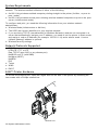
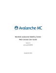
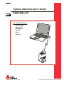
9493™ Printer Hardware
To access the Ethernet port, open the hinged door on the side of the printer by loosening the
two screws with a Phillips screwdriver.
Ethernet Port
1-2 System Administrator’s Guide
C O N F I G U R I N G T H E 8 0 2 . 11 B / G A N D I P
SETTINGS
2
Configuring the Print Server
To configure the print server for an 802.11b/g wireless network, you must set the wireless mode
(Ad-Hoc or infrastructure), SSID, channel (Ad-Hoc mode only), data rate and security. All nodes
of a wireless network need to have the same settings to communicate with each other.
There are several ways to configure your print server. You can
♦ send console commands using a utility such as Monarch® NetManager. See “Installing the
Software” for NetManager information.
♦ use a Web browser. See Chapter 4, “Using a Web Browser” for more information.
♦ use the Sierra Sport Configurator with Avalanche. See Chapter 5, “Using the Sierra Sport
Configurator” for more information.
♦ use Telnet. See Chapter 6, “Telnet Console Commands” for a list of supported commands.
♦ select the RF Network (9460) and Network (9493) printer menus. See “Setting Up Using the
Printer’s Menu.” The printer’s menus allow you to do basic setup.
Before You Begin
Configure your computer to communicate on a wireless network before you continue.
♦ To connect a device using an access point, set your computer to infrastructure mode.
♦ To connect directly to a device without an access point, set your computer to Ad-Hoc
Computer-to-Computer mode, or whatever mode your adapter uses to communicate without
an access point.
♦ To use Ad-Hoc mode, temporarily disable security on your access point. After the print
server is configured, re-enable security on the access point.
♦ To use WEP (Wired Equivalent Privacy) encryption or other advanced security, such as WPA
(Wi-Fi Protected Access), on your wireless network, temporarily disable the security on your
computer in order to configure the print server. To allow non-secure clients to communicate
with each other, temporarily change the wireless mode of your host to Ad-Hoc mode.
♦ To use TCP/IP, note your computer’s IP address. The print server needs to be on the same
IP segment as the other nodes on your network in order to communicate.
♦ You need a good signal between your computer and the access point to communicate.
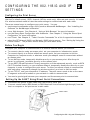
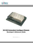
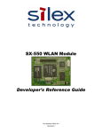
Setting Up the 9460™ Using Direct Serial Connections
1.
2.
Disconnect the printer’s radio cable from the printer’s serial port.
Connect a serial cable (DB9 female to DB9 female all lines wired straight through) from the
host or computer to the print server’s radio cable.
Radio Cable
Configuring the 802.11b/g and IP Settings 2-1
3.
Turn on the printer and configure using Telnet or other communications program.
4.
Connect the printer’s radio cable to the printer’s serial port.
Serial Port
Radio Cable
5.
Turn off the printer, wait a few seconds, and then turn on the printer.
Your printer is ready to use.
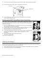
Setting up the 9493™ Using Direct Serial Connections
Use a serial cable or a USB cable for direct communication with the printer.
The USB port can function as either a serial port or a parallel port. Refer to
the System Administrator’s Guide for more information about changing the
USB port’s function.
1.
6.
7.
8.
9.
Open the hinged cable door on the side of the printer by loosening the
two screws with a Phillips screwdriver.
Plug the DB9 connector into the DB9 port or plug a USB type A or USB
mini-B connector into the corresponding USB port as show.
Place the cable in one of the cable cavities.
Turn on the printer and configure using Telnet or other communications
program. See Chapter 6, “Telnet Console Commands” for more
information.
Turn off the printer, wait a few seconds, and
then turn on the printer.
DB9 cable show n
Your printer is ready to use.
Installing the Software
USB mini-B cable
The software works with Microsoft Windows NT 4, 2000, XP, and Vista™ operating
systems. Follow these steps to install the NetManager software and configure the print server.
You can also download the utility from our Web site.
1.
2.
Insert the Monarch® Printer Documentation CD-ROM (TC9X00SWP) into your computer.
Select Drivers & Utilities, then NetManager.
2-2 System Administrator’s Guide
3.
Follow the on-screen instructions for installing the utility. When NetManager starts for the
first time, you see the NetManager Welcome screen. You are prompted to enter a View
Name (sets up how print servers are discovered and displayed on your network). Then,
select the protocol and filter settings or “Automatically create a view with default settings.”
Select Finish to begin searching for print servers. NetManager gets the information from the
print server(s) and lists the server name, IP address, and hardware (Ethernet) address.
The default name of the print server is PXRxxxxxx, where xxxxxx is the last 6 digits of the
hardware address (for example, PXR08B2C7).
Note: It might take a minute or two for the print server to appear, especially on a large
wireless network.
5. When you see the print server you need to configure in the list, highlight it and click the
Configuration tool.
Note: A wireless signal of less than 50% on the Wireless Status screen, could affect printing
performance. To improve the signal strength, move the print server closer to the
computer or access point and away from other radio devices such as Bluetooth®
wireless devices, microwave ovens, or 2.4 gigahertz cordless phones.
6. Configure your print server to the settings you need. Many of the fields are automatically
configured to match the network being used, so you may not need to change the Wireless
Mode, RF Channel, SSID, and Data Rate settings unless you need to change the print
server to a different wireless network.
♦ To use WEP encryption or other advanced security, enable the security and enter the
appropriate key(s).
♦ To use TCP/IP without a DHCP server, manually assign a valid IP address, subnet mask,
and gateway and then set the boot method to static.
Note: If you are using DHCP on your network, the print server may have acquired valid IP
settings at this point and no further configuration is necessary. This works if your DHCP
server allows the print server to keep this address permanently. However, in most
cases, use a static address outside the range reserved for DHCP (Refer to your DHCP
server documentation for details). When you configure your printer port, it goes to a
static IP address.
7. When you are done configuring, click OK. You are prompted to save changes and reset the
print server. Click OK. The print server resets with your new configuration. This may take
several minutes.
4.
Setting Up Using the Printer’s Menu
You can use the printer’s menu to configure some basic network settings. Follow the
instructions for your printer: 9460 or 9493.
Configuring the 802.11b/g and IP Settings 2-3
Setting Up the 9460™ Printer
Use these instructions to set up a 9460 printer using the printer’s RF Network menu in the
printer’s Tool Box.
1.
Turn on the printer by pressing and holding the power button (P) until the display turns on.
The display flashes printer version information and battery charging status.
E B
F
Init Radio……….
When you see “Init Radio”, the printer is waiting for the wireless print server to initialize.
Next, you may see
Ready
p
<T>
Display
Indicates
Ready
The printer is in Ready mode to send and receive data.
The printer is connected to a network (peer-to-peer or infrastructure
mode). Press A under <T> to display the printer’s IP address, then
press A under
to print a network information label with the device
name, IP address, and MAC address as a bar code. See “Printing a
Network Information Label” for more information.
Press any button to return to Ready mode.
<T>
The printer is not connected to a network.
2.
Press A under p.
E B
F
R
T
X
You see the battery indicator E (empty) and F (full). As you use the printer, the battery
indicator line gets closer to E (empty), instead of F (full). Recharge the battery when
the line is by the E.
3.
Press T (Tool Box) to enter the menu.
Tool Box
Language
E
D
4.
Tool Box is highlighted. Press E to select Tool Box.
Enter Password
5.
Press the navigational buttons in this order: Left, Left, Left, Right, and Left.
Diagnostics
Online Diag.
E
D
2-4 System Administrator’s Guide
6.
Press D until Setup is highlighted.
Setup
Service
E
U
7.
8.
D
Press E to select Setup.
From the Setup menu, press D until you see RF Network. Press E to select RF Network.
The RF Network menu allows you to check the printer’s status, configure the RF network
settings, print RF settings, and reset the radio.
To exit, press F at any time.
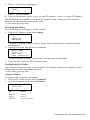
Checking the Status
This option displays the status of the RF network.
1.
From the RF Network menu, select Status.
192.0.0.192
1.0
(2006.11.20)
PXR1E858F
The local IP address, firmware version, printer model, board revision, and device name
are displayed.
2.
Press A to see the next screen of information.
0040171 E 858F
Protocol : TCP
State : Wait
Radio : IEEE 802.11g
The MAC address, protocol, current state, and radio type are displayed.
3.
Press any A to return to the RF Network menu.
Configuring the Printer
The Configure menu allows you to set the printer’s IP address, subnet mask, gateway, power
mode, protocol, SSID, and escape character.
To exit, press F at any time.
Setting the IP Address
This option sets the printer’s IP address.
1.
2.
From the RF Network menu, select Configure.
From the Configure menu, select IP Address.
IP Address
192.0.0.192
E
R
+
For:
Select:
BOOTP
0.0.0.0
DHCP
0.0.0.1
Static IP
nnn.nnn.nnn.nnn
Configuring the 802.11b/g and IP Settings 2-5
Use the A buttons as shown in the following table:
3.
E
Press A to
R
Press A to
+
Press A to
Saves the setting
Scrolls through the positions
from left to right
Increments the current position
setting by 1
When the setting you want is displayed, press E to save the setting. You return to the
Configure menu.
Setting the Subnet Mask
This option sets the printer’s subnet mask.
1.
From the Configure menu, select Subnet Mask.
Subnet Mask
255.255.000.000
E
R
+
Use A as shown in the following table:
2.
E
Press A to
R
Press A to
+
Press A to
Saves the setting
Scrolls through the positions
from left to right
Increments the current position
setting by 1
When the setting you want is displayed, press E to save the setting. You return to the
Configure menu.
Setting the Gateway
This option sets the printer’s router (gateway) address.
1.
From the Configure menu, select Gateway.
Gateway
000.000.000.000
E
R
+
Use A as shown in the following table:
2.
E
Press A to
R
Press A to
+
Press A to
Saves the setting
Scrolls through the positions
from left to right
Increments the current position
setting by 1
When the setting you want is displayed, press E to save the setting. You return to the
Configure menu.
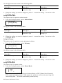
Setting the Power Mode
This option sets the power mode.
3.
From the Configure menu, select Power Mode.
Power Mode
X CAM
3 PSP
E
D
The choices include CAM (Continuous Awake Mode) or PSP (Power Save Protocol).
PSP conserves battery power. CAM means the printer is continuously receiving and
transmitting data. This mode uses battery power quickly.
2-6 System Administrator’s Guide
4.
Use D to select the power mode you want. Press E to save the setting.
If you select PSP, you are prompted to enter a PSP algorithm between 1-5.
3 3
X 4
E
U
D
1 = shortest sleep time (uses battery power quicker, but responds faster); 5 = longest
sleep time (optimal battery conservation, but responds slower).
5.
Use U or D to select the PSP algorithm you need. Press E to save the setting. Select
Exit to return to the Configure menu.
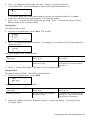
Setting the Port
This option sets the port.
1.
From the Configure menu, select Port: TCP or LPD.
Protocol
3 TCP
X LPD
E
U
2.
D
Use D to select the protocol you want. For example, if you select LPD, you must specify a
raw printer port:
Port
+ 09100
E
U
+
Use A as shown in the following table:
E
Press A to
R
Press A to
+
Press A to
Saves the setting
Scrolls through the positions
from left to right
Toggles between + or –; also
increments the current position
setting by 1
3. Press E to save the setting. You return to the Configure menu.
Setting the SSID
This option sets the SSID. The SSID is case-sensitive.
1.
From the Configure menu, select SSID.
SSID
ABC 1234
E
R
+
Use A as shown in the following table:
2.
E
Press A to
R
Press A to
+
Press A to
Saves the setting
Scrolls through the positions
from left to right
Increments the current position
setting by 1 and scrolls through
alpha/special characters
When the setting you want is displayed, press E to save the setting. You return to the
Configure menu.
Configuring the 802.11b/g and IP Settings 2-7
Setting the Command Escape Character
1.
2.
3.
This option allows you to set or view the Command Escape Character (CEC).
Run-time messages from the radio begin with the CEC and the default is the pound sign (#),
which has a decimal value of 35. You may need to change the default CEC character if it
conflicts with other data, because an unexpected operation could occur. The range is a
decimal value between 1 and 255.
From the Configure menu, select Escape.
Escape Char
+ 35
E
R
+
Use A as shown in the following table:
4.
5.
E
Press A to
R
Press A to
+
Press A to
Saves the setting
Scrolls through the positions
from left to right
Increments the current position
setting by 1
When the setting you want is displayed, press E to save the setting. You return to the
Configure menu.
Press F to exit.
When you select “Exit” after configuring, you will see
Configure
Save Settings ?
E
X
To save all the configuration settings, press E. To exit without saving the configuration
settings, press X . Press F until you see “Ready.”
Note:
You must reset the RF network before your changes take effect. See “Resetting the RF
Network” for more information.
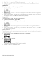
Printing a Network Information Label
You can print a network information label with the device name, IP address, and MAC address
as a Code 128 bar code. You can also print the network information as a Code 39 bar code with
the correct MIF settings.
1.
2.
Turn on the printer.
Press A under <T>. You see the printer’s IP address. For example,
192.0.0.192
3.
Press A under
to print a network information label.
Sample Label
2-8 System Administrator’s Guide
Setting Up the 9493™ Printer
Use these instructions to set up a 9493 printer using the printer’s Network Setup menu.
1.
Turn on the printer by pressing p.
The display flashes printer version information and battery charging status. Then you
may see
The J indicates the wireless signal strength.
Note:
2.
When using wired Ethernet, connect the network cable before you turn on the printer.
The print server cannot detect the connection if the printer is already on.
Display
Indicates
Ready
The printer is in Ready mode to send and receive data.
M
The printer is connected to a network (peer-to-peer or infrastructure
mode). Press A under M to display the printer’s IP address. Press I
then E to view network information. Press
to print a network
information label with the device name, IP address, and MAC address as
a bar code. See “Printing a Network Information Label” for more
information.
Press E to return to Ready mode.
J
Shows the wireless signal strength between the printer and the network.
N
The printer is not connected to a wireless network.
N
The printer is connected to a wired Ethernet 802.3 network. Press A
under n to display the printer’s IP address. Press I then E to view
to print a network information label with the
network information. Press
device name, IP address, and MAC address as a bar code. See “Printing
a Network Information Label” for more information.
Press E to return to Ready mode.
M
The printer is not connected to a wired Ethernet network.
Press A under P.
You see the Pause screen with the battery indicator E (empty) and F (full). As you use
the printer, the battery indicator line gets closer to E, instead of F. Recharge the battery
when the line is by the E.
Configuring the 802.11b/g and IP Settings 2-9
3.
4.
5.
Press A under T to enter the main menu.
Tools is highlighted. Press e to select Tools.
Press A under the corresponding number to enter the following default password:
1, 1, 1, 3, 1.
6.
Press D until Setup is highlighted. Press e to select Setup.
7.
Press D until Network is highlighted. Press e to select Network.
Using the Network Menu
The Network menu allows you to check the printer’s status, configure the network settings, print
the settings, and reset the radio.
To exit, press E until you return to the Pause screen.
Checking the Status
This option displays the status of the network.
1.
From the Network menu, select Status.
You see the printer model, firmware version, and bootloader version.
2.
Press E to move through the next four screens of information.
You see the radio type and MAC address, local IP address, SSID, protocol, network
mode, status, and connection speed.
3.
Press E again to return to the Network menu.
Configuring the Printer
The Configure menu allows you to set the printer’s IP address, subnet mask, gateway, power
mode, port, SSID, encryption type, keys, and escape character. You can also enable or disable
Ad-Hoc mode.
From the Network menu, select Configure.
To exit, press E until you return to the Pause screen.
2-10 System Administrator’s Guide
Setting the IP Address
This option sets the printer’s IP address.
1.
From the Network Configure menu, select IP Address.
2.
Press D or U to increase or decrease the highlighted number. Press L or R to highlight a
different number.
When you are finished, press R until you see e. Then press e to save the address and
return to the Configure menu. Press X to exit without saving changes.
3.
Setting the Subnet Mask
This option sets the printer’s subnet mask.
1.
From the Network Configure menu, select Subnet Mask.
2.
Press D or U to increase or decrease the highlighted number. Press L or R to highlight a
different number.
When you are finished, press R until you see e. Then press e to save the address and
return to the Configure menu. Press X to exit without saving changes.
3.
Setting the Gateway
This option sets the printer’s router (gateway) address.
1.
From the Configure menu, select Gateway.
2.
Press D or U to increase or decrease the highlighted number. Press L or R to highlight a
different number.
When you are finished, press R until you see e. Press e to save the address and return to
the Configure menu. Press X to exit without saving changes.
3.
Setting the Power Mode
This option sets the power mode to CAM (Continuous Awake Mode) or PSP (Power Save
Protocol). PSP conserves battery power. CAM means the printer is continuously receiving and
transmitting data. This mode uses battery power quickly.
1.
From the Configure menu, select Power Mode.
A checkmark indicates the current option.
2. Press U or D until you see the power mode you need. Press e to enable it.
Note: If you select PSP, you are prompted to enter a PSP algorithm between 1-5. 1 - shortest
sleep time (uses battery power quicker, but responds faster); 5 - longest sleep time
(optimal battery conservation, but responds slower).
Configuring the 802.11b/g and IP Settings 2-11
3.
4.
Press U or D to select the PSP algorithm you need.
Press e to save the setting and return to the Configure menu. Press X to exit without
saving changes.
Setting the Port
This option sets the port. The default port is 9100.
1.
From the Configure menu, select Port.
Press D or U to increase or decrease the highlighted number. Press L or R to highlight a
different number.
3. When you are finished, press R until you see e. Press e to save the setting and return to
the Configure menu. Press X to exit without saving changes.
Setting the SSID
2.
This option sets the SSID. The SSID is case-sensitive.
1.
From the Configure menu, select SSID.
The default or last-saved SSID appears, for example:
2.
3.
Press D or U to change the highlighted character. Press L or R to highlight a different
character.
When you are finished, press R until you see e. Press e to save the setting or press X to
exit without saving changes.
Enabling Ad-Hoc Mode
The default mode for the radio is infrastructure (access point). You must enable Ad-Hoc mode to
connect peer-to-peer.
1.
In the Configure menu, Press D or U until AD HOC is highlighted.
2.
Press e to enable AD HOC.
A checkmark appears when AD HOC mode is enabled.
3.
Press E to return to the Network menu.
2-12 System Administrator’s Guide
Setting the Encryption
This option allows you to set the printer’s encryption method to None,
WEP 64, WEP 128, WPA, WPA2, or WPA2/WPA. The default is None (no encryption).
1.
From the Configure menu, select Encryption.
A checkmark indicates the current setting.
Press D or U until you see the encryption you need, then press e to enable it and return to
the Configure screen. Press X to exit without saving changes.
Note: When you use encryption, you must set the keys to secure your network. See “Setting
the Encryption Keys” for more information.
2.
Setting the Key Index
This option sets the key to use for the selected encryption method.
See “Basic Security Configurations” for more information on encryption keys.
1.
From the Configure menu, select Keys.
2.
Select Index.
You can select up to four 104-bit keys using keys 1-4, or up to two 128-bit keys using
keys 1 and 3.
3.
4.
Select the key you need and press e to save the setting or press X to exit without saving
changes. You return to the Keys menu.
Enter the key values. See “Setting the Encryption Keys” for more information.
Setting the Encryption Keys
Use this option to set the key values for encryption. Once you save a key and exit the option,
you cannot view the key values. There are four keys. Refer to “Basic Security Configurations” in
Chapter 4 for more information on setting encryption key values based on your encryption
method.
Note:
Since you cannot view key values, keep a list of your key values in a safe place for
future reference.
After you set the key values, select a key to use based on your network’s encryption method.
See “Setting the Key Index” for more information.
1.
From the Configure menu, select Keys.
Configuring the 802.11b/g and IP Settings 2-13
2.
Press D or U until you see the key you need to set, then press e to edit the value.
For example:
3.
Press D or U to scroll through the hex characters for each field. The hex characters appear
in the box and the ASCII equivalent character appears under the hex character.
Press R to select the character shown and move to the next field.
When you are finished, press R until you see e. Press e to save the setting or press X to
exit without saving changes. You return to the Keys menu.
4.
5.
Setting the Escape Character
1.
2.
3.
4.
5.
This option allows you to set or view the Escape Character (EC).
Run-time messages from the radio begin with the EC and the default is the pound sign (#),
which has a decimal value of 35. You may need to change the default EC character if it
conflicts with other data, because unexpected operation could occur.
From the Configure menu, select Escape Char.
Press D or U to decrease or increase the decimal value.
Press L or R when you are finished. Press e to save the setting or X to exit without
saving changes. You return to the Configure menu.
The radio is now configured. Press E until you return to the Pause screen.
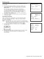
Printing a Network Information Label
You can print a network information label with the device name, IP address, and MAC address
as a Code 128 bar code. You can also print the network information as a Code 39 bar code with
the correct MIF settings.
1.
2.
Turn on the printer.
Press M or n. You see the printer’s IP address. For example,
3.
Press
to print a network information label.
Sample Label
2-14 System Administrator’s Guide
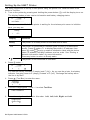
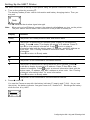
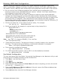
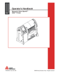
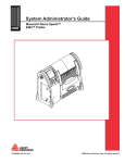
Printing Info
Do not use supply smaller than 2012 or information may print
off the label.
1.
From the RF Network (9460) or Network (9493) menu,
select Print Info. Three wireless network information
labels print.
MAC:
Prin ter Mo de l:
00-a0 -f8-5f-72-0b
9 493 SNP
Boot Ver :
1.0
Application:Peg3-1.20 (2008.06 .10)
The first label contains radio version information.
The second label contains the RF (wireless) settings,
including the SSID, security, and signal strength.
The third label contains TCP/IP settings, including the
IP address, boot method, etc.
2.
Mona rch Prin t Se rv er Status
Label 1
Press the navigation button to return to the RF Network
or Network menu.
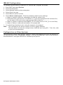
Resetting the Radio
After you save the configuration, you must reset the radio
before the changes take effect. When you select “Reset,”
the radio reinitializes.
Note:
3.
4.
You may lose your current connection and application.
Resetting the network may take up to one minute before
you can access the wireless print server (radio).
From the RF Network or Network menu, select Reset.
You may see:
Wireless In fo rmation
SSID:
MON 123
Mode :
INFRAST RUCTURE
S pee d :
5 4 mb ps
Secu rity : Disabled
Sig. Streng th :
51
Actual SSID:
MON 123
Assoc. AP MAC: 00-a0 -f8-aa-83 -25
For the 9460, press any navigation button to return to the
RF Network. The 9493 returns to the Network menu
automatically.
Label 2
T CP /IP
IP Address:
Subnet Ma sk :
R ou ter :
(set manually)
Boo t Me tho d:
Boot Retrie s:
Timeout:
Keep aliv e :
192.0.0.192
255.255.25 5.0
192.0.1 92 .0
STAT IC
4
0 min
1 min
Label 3
Configuring the 802.11b/g and IP Settings 2-15
2-16 System Administrator’s Guide
SELECTING A MANAGEMENT METHOD
3
There are a variety of ways to configure and monitor the network printer. This
chapter explains how to use NetManager, HP JetAdmin, HP Web JetAdmin, UNIX, or Sun
Solaris.
See Chapter 4, “Using a Web Browser” to configure the network printer via your Browser.
See Chapter 5, “Using the Sierra Sport Configurator” to configure the network printer via
Avalanche software.
HP JetAdmin Utility
This HP Windows-based utility (works transparently with JetAdmin) can be downloaded from the
HP Web site (www.hp.com).
Note:
The print server does not appear in the list of configured servers unless TCP/IP or IPX
is running on the computer.
HP Web JetAdmin Utility
This HP utility for Windows NT Advanced Server and Windows 2000 can be downloaded from
the HP Web site (www.hp.com). Once it is installed, a web browser on any computer that has
access to the Windows NT/2000 server may be used to access the print server.
Microsoft Windows Network Configuration
The print server includes the NetManager software for printing from Windows computers over an
802.11b/g wireless link. This software creates a network port on the Windows system, which
acts like a normal parallel port. As a result, it works transparently with any standard Windows
printer driver and application program. Since this software uses the industry-standard TCP/IP
protocol, it can be used with IP routers and other IP-based equipment.
Additional Windows Configuration Methods
The print server is also compatible with other methods of printing from Windows. These include
the Standard TCP/IP port option in Windows 2000/XP, and the LPR port option in Windows NT
that are built into the operating system.
UNIX Network Configuration
The print server appears to the network as a UNIX host computer with a unique IP address
running the line printer daemon (LPD) protocol. As a result, any host computer that supports
the Berkeley remote-lpr command can spool jobs to the print server without the need for any
special software on the host computer.
Note:
Before configuring a UNIX print queue, the print server must have a valid IP address.
Selecting a Management Method 3-1
Berkeley UNIX Host Configuration
Berkeley UNIX host computers include Linux, Digital Equipment Corporation Digital UNIX,
OSF/1, and ULTRIX; Compaq Tru64 UNIX; SunOS (not Solaris), SCO UNIX; and many others.
Sun Solaris, HP/UX, IBM AIX users should skip to the appropriate sections later in this manual.
♦ Do not use the Linux X-Windows graphical user interface printer configuration utility,
because it does not work with Monarch® print servers. Instead, Linux users should follow
the configuration steps listed in this section.
♦ SCO UNIX users should use the rlpconf command to create a printer and automatically
configure the /etc/printcap file (you will still need to edit the /etc/hosts file). Enter the print
server's service name (PXRxxxxxx_P1) as the name of the printer and enter the name of the
print server that you assigned in the /etc/hosts file as the remote host name; note that
because this name must be unique for each printer, we recommend using the PXRxxxxxx_P1
service instead of the normal BINARY_P1 service.
1. Edit the /etc/hosts file: (or equivalent local host table). For example:
192.189.207.33
2.
MonarchPrinter
Edit the printcap file: An example of a typical entry in the printcap file is:
MonarchPrinter:\
:lp=:\
:rm=MonarchPrinter:\
:rp=BINARY_P1:\
:sd=/usr/spool/lpd/MonarchPrinter:
"MonarchPrinter" is the queuename.
"MonarchPrinter" matches the name in the hosts file.
"BINARY_P1" is the print server's service name.
Note:
Use TEXT_P1 instead of BINARY_P1 for text files.
"sd" is the spool directory.
3.
Create the spool directory: The lpd spool directory is usually located in the /usr/spool
directory. To create a new spool directory, use the mkdir command; for example:
mkdir /usr/spool/lpd/MonarchPrinter
4.
Print using the standard lpr command:
lpr –PMonarchPrinter
5.
filename
For AT&T based UNIX systems, such as SCO, use the standard lp command:
lp –dMonarchPrinter
filename
Sun Solaris Configuration
To use a print server with Sun Solaris, first use the Host Manager in the Admintool utility to add
the print server IP address and name to the /etc/hosts file.
1.
2.
3.
4.
5.
6.
Click None - Use /etc files on host.
Click Apply.
Click Edit and then Add Host.
Enter the print server name as the Host Name (this name is anything you want, but should
not have an "_" character in it).
Enter the IP address and Ethernet address of the print server (the Ethernet address has
the format aa:bb:cc:dd:ee:ff)
Select Add and then close the Host Manager windows
3-2 System Administrator’s Guide
7.
Use the Printer Manager in the Admintool utility under Open Windows
as follows:
Select Edit
Select Add
Select Add Access to Remote Printer
At the PrinterName prompt, type any name for the print queue
At the Printer Server prompt, type:
name\!servicename
(for example, MonarchPrinter\!BINARY_P1), where:
name matches the print server name as entered in the host’s table.
servicename is the print service name. For binary graphics files use the service
BINARY_P1; for text files use the service TEXT_P1.
8. The Print Server OS is set to BSD (this is the default setting).
9. Select Add.
10. To print, use the standard lp command; for example:
lp –dMonarchPrinter
filename
Notes:
♦ We recommend using the /etc/hosts file for the printer name rather than NIS or other name
services.
♦ Due to a bug in the Sun lpd implementation on Solaris 2.4 and earlier releases, there may be
problems printing very long print jobs.
The workaround is to configure the print server as an HP JetDirect card using the HP
JetAdmin for UNIX software.
♦ Solaris print queues can also be configured from the UNIX shell using the lpadmin command.
HP/UX Configuration
To configure a print server using HP/UX 10.x, use the same program and these steps:
When you get a list of options, select Printers and Plotters.
Select LP Spooler.
Select Printers and Plotters.
Select Actions and then Add Remote Printer/Plotter.
Enter any name as the Printer Name (this is the name of the print queue).
Enter the IP address of the print server as the Remote System Name.
Enter the print server service name (BINARY_P1 for binary files or TEXT_P1 for text files)
as the Remote Printer Name.
8. Check the box next to Remote Printer is on BSD System.
9. You may accept the default values for the remaining items.
10. Click OK to configure the printer.
11. You should now be able to print using the lp -d command with the printer name.
1.
2.
3.
4.
5.
6.
7.
Notes:
♦ The configuration for HP Distributed Print Services and for earlier versions of HP/UX is
slightly different.
♦ The print server can also be configured as a JetDirect card using HP/UX. To do this, you will
need the HP UNIX Host Printing Software (part of HP's JetAdmin for UNIX).
Selecting a Management Method 3-3
IBM AIX Configuration
To configure a print server on IBM AIX 4.x, use the SMIT program as follows:
Enter SMIT and select Devices.
Select Printer/plotter.
Select Manage remote printer subsystem.
Select Client services.
Select Remote printer queues.
Select Add a remote queue. Enter the following remote queue settings:
♦ Name of queue to add (user selectable) Activate the queue (Yes).
♦ Destination host (print server’s IP address; or if you have configured the /etc/hosts file,
use the name of the print server that you specified in that file).
♦ Name of queue on remote printer BINARY_P1 for binary files or TEXT_P1 for text files).
♦ Name of device to add (user selectable; for example lp0).
7. You should now be able to print using the normal lp -d command.
Note: The configuration for earlier versions of AIX is slightly different.
The print server can also be configured as a JetDirect card using AIX. To do this, refer
to your AIX documentation.
1.
2.
3.
4.
5.
6.
Configuration on Other Systems
The print server can be used with any computer system that supports the LPR/LPD protocol or
HP JetDirect (port 9100 is the default; however, it can be reconfigured). Refer to the system’s
documentation to configure LPR/LPD or JetDirect print queues.
3-4 System Administrator’s Guide
4
USING A WEB BROWSER
You can configure and manage the printer and print server using your Web Browser:
Microsoft Internet Explorer, version 6.0, or greater or Netscape Communicator, version 4.7
or greater or Mozilla Firefox®.
Notes:
♦ The screen pictures shown in this manual may not exactly match the software.
♦ The recommended screen area resolution for your computer is 1024 x 768
pixels.
♦ Before you begin, you need to know your printer’s IP address. The printer
should be turned on and ready to receive data.
It may take a minute or more before a wireless connection is associated between the print
server and the access point. When the printer is connected, you see
Ready
II
<T>
9460 Printer
9493 Printer Wireless
9493 Printer Ethernet
The printer is ready to receive data.
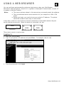
Logging In
1.
2.
Start your Web browser.
Type in your printer’s IP address and press Enter. For example, 192.0.0.192.
3.
From the side menu, click Login.
Using a Web Browser 4-1
4.
5.
Type access for the password. To change the password, see “Setting the Network Card
Access Password,” for more information.
The password is case-sensitive and saved in the printer’s flash memory.
Click Submit.
The Printer Status page appears with information about your printer, including printer name,
description, firmware version and more. Use the following sections to configure the print server
using your Web browser. Only configure the settings required for your network/printer.
Contacting Us
From the Printer Status page, click the Paxar link if you need to contact us.
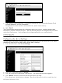
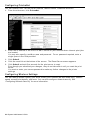
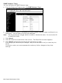
Configuring the Server Settings
You can change the name, location, and other information for your server as well as set SNMP
parameters, reset the server and restore server default settings.
1.
From the side menu, click Server Settings.
2.
3.
4.
Enter your information and click Submit.
Click the reset link at the bottom of the screen. The Reset Server screen appears.
Click Submit and wait five seconds for the print server to reset.
Even though you submitted your changes, they do not take effect until you reset the print
4-2 System Administrator’s Guide
server.
You must re-enter your access password to make any further changes to the printer
settings.
Configuring the Print Port Settings
You can view available ports, port settings, cancel print jobs, and view the job log for each
available port.
1.
2.
From the side menu, click Printer Port. The available ports are listed.
If more than one port is available, click the name of the port you want to modify. The Print
Port Settings screen appears and displays your communication settings.
Note:
Port Type, Baud Rate, Bits per character, Stop Bits, Parity, and Flow Control settings
cannot be changed.
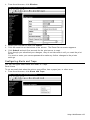
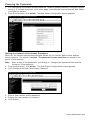
Configuring Print Services
You can configure the service ports if necessary.
1.
2.
From the side menu, click Print Services. The Configure Service screen appears.
Click the name of the service you want to modify from the available services listed.
The Configure Service page allows you to specify ports, determine network protocols,
set filters and more.
3.
Enter the new attributes and click Submit.
Using a Web Browser 4-3
4.
5.
Click the reset link at the bottom of the screen. The Reset Server screen appears.
Click Submit and wait five seconds for the print server to reset.
Even though you submitted your changes, they do not take effect until you reset the print
server.
You must re-enter your access password to make any further changes to the printer
settings.
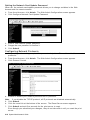
Setting Netware Parameters
You can enable Netware, set frame types, and passwords.
1.
From the side menu, click NetWare.
2.
Click the name of the enabled service to modify the NetWare parameters for that service.
See “Configuring Print Services” for more information.
You can also change the network frame type (packet format), NetWare password, or
disable NetWare.
3.
4.
5.
When you are finished, click Submit.
Click the reset link at the bottom of the screen. The Reset Server screen appears.
Click Submit and wait five seconds for the print server to reset.
Even though you submitted your changes, they do not take effect until you reset the print
server.
You must re-enter your access password to make any further changes to the printer
settings.
4-4 System Administrator’s Guide
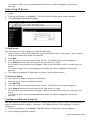
Changing TCP/IP Settings
You can enable TCP/IP, select applications, set the IP Address, Subnet Mask, and more.
1.
From the side menu, click TCP/IP.
Click the name of the enabled service to modify the TCP/IP parameters for that service. See
“Configuring Print Services” for more information.
3. You can change protocols, assign an IP address, subnet mask, gateway and more.
Note: If you disable the IP protocol, you will not be able to configure the printer from your
Web browser.
4. When you are finished, click Submit.
5. Click the reset link at the bottom of the screen. The Reset Server screen appears.
6. Click Submit and wait five seconds for the print server to reset.
Even though you submitted your changes, they do not take effect until you reset the print
server.
You must re-enter your access password to make any further changes to the printer
settings.
2.
Using a Web Browser 4-5
Configuring PrintraNet
You can enable POP3, set the Server Address, Mailbox Name, Password and more.
1.
From the side menu, click PrintraNet.
2.
Enter the IP address of the POP3 or SMTP server on your network where internet print jobs
are located.
You may also specify a mailbox name and password. For no password required, enter a
single space in the field provided.
3.
4.
5.
Click Submit.
Click the reset link at the bottom of the screen. The Reset Server screen appears.
Click Submit and wait five seconds for the print server to reset.
Even though you submitted your changes, they do not take effect until you reset the print
server.
You must re-enter your access password to make any further changes to the printer
settings.
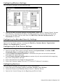
Configuring Wireless Settings
You can change modes, specify your SSID, modify your channel (Ad-Hoc mode only), network
speed, access point density, and more. You can also configure network security. See
“Configuring Network Security” for more information.
4-6 System Administrator’s Guide
1.
From the side menu, click Wireless.
2.
3.
4.
Select your information and click Submit.
Click the reset link at the bottom of the screen. The Reset Server screen appears.
Click Submit and wait five seconds for the print server to reset.
Even though you submitted your changes, they do not take effect until you reset the print
server.
You must re-enter your access password to make any further changes to the printer
settings.
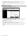
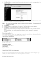
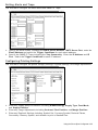
Configuring Alerts and Traps
You can configure email alerts and SNMP IP Traps.
Email Alerts
To set an email alert when the printer goes offline, has a paper jam, or other error:
1.
From the side menu, click Alerts and Traps.
Using a Web Browser 4-7
2.
Click Email Alerts to setup the mail server and select users to receive messages about the
printer’s status.
Enter your SMTP server, email address, server port, and the trigger conditions for an email
alert. You can enter up to eight email addresses.
Note: The S1 port acts as a toggle switch to enable or disable the alerts. You must select S1
to enable the alerts.
4. Click Submit.
5. Click the reset link at the bottom of the screen. The Reset Server screen appears.
6. Click Submit and wait five seconds for the print server to reset.
Even though you submitted your changes, they do not take effect until you reset the print
server.
You must re-enter your access password to make any further changes to the printer
settings.
3.
Receiving An Alert
When the printer goes offline, has a paper jam, or any other error that you selected notification
for, a similar email appears in the specified User’s inbox:
The text of the email follows:
Pegasus III Printer Alert
Prn IP: 192.0.0.192
Prn Display: Off-line
Prn MAC Addr: 10.10.1.1
Prn Location:
System Contact:
Please DO NOT REPLY to this message
Perform the appropriate action to correct the problem. Make sure the printer’s display says
“Ready” and shows the antenna icon after the problem is corrected.
4-8 System Administrator’s Guide
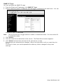
SNMP IP Traps
You can configure the SNMP IP traps.
1.
2.
From the Alerts and Traps page, click SNMP IP Traps.
Enter a community name, IP address, and the trigger conditions for an email alert. You can
enter up to eight IP addresses.
Note: The S1 port acts as a toggle switch to enable or disable the alerts. You must select S1
to enable the alerts.
3. Click Submit.
4. Click the reset link at the bottom of the screen. The Reset Server screen appears.
5. Click Submit and wait five seconds for the print server to reset.
Even though you submitted your changes, they do not take effect until you reset the print
server.
You must re-enter your access password to make any further changes to the printer
settings.
Using a Web Browser 4-9
SNMP Netware Traps
You can configure the SNMP Netware traps.
1.
From the Alerts and Traps screen, click SNMP Netware Traps.
Enter a community name, IPX address, IPX Node address, and the trigger conditions for an
email alert. You can enter up to four IPX addresses.
Note: The S1 port acts as a toggle switch to enable or disable the alerts. You must select S1
to enable the alerts.
3. Click Submit.
4. Click the reset link at the bottom of the screen. The Reset Server screen appears.
5. Click Submit and wait five seconds for the print server to reset.
Even though you submitted your changes, they do not take effect until you reset the print
server.
You must re-enter your access password to make any further changes to the printer
settings.
2.
4-10 System Administrator’s Guide
Changing the Passwords
1.
2.
You can change the network access password, network update password, configure network
security, IP access or protocol, print a test page, or access the console from the Web Admin
Configuration screen.
From the side menu, click Admin. The Web Admin Configuration screen appears.
Setting the Network Card Access Password
When set, the network card access password allows you to view the Web browser and the
remote console. The default is access. The password is case-sensitive and stored in the
printer’s flash memory.
Note:
1.
2.
Make a note of the password if you change it. Changing the password also restricts
access to Telnet sessions.
From the side menu, click Admin. The Web Admin Configuration screen appears.
Click Configure Network Card Access Password.
3.
4.
5.
Enter a new network access password.
Retype the new password to confirm it.
Click Submit.
Using a Web Browser 4-11
Setting the Network Card Update Password
When set, the network card update password allows you to change variables in the Web
browser and the remote console.
1.
2.
From the side menu, click Admin. The Web Admin Configuration screen appears.
Click Configure Network Card Update Password.
3.
4.
5.
Enter a new network update password.
Retype the new password to confirm it.
Click Submit.
Configuring Network Protocols
1.
2.
3.
Only configure the settings required for your network/printer. To enable or disable
protocols:
From the side menu, click Admin. The Web Admin Configuration screen appears.
Click Protocol Control.
4. Enable or disable your network protocols and IP protocols.
Note: If you disable the TCP/IP protocol, all IP protocols are disabled automatically.
5. Click Submit.
6. Click the reset link at the bottom of the screen. The Reset Server screen appears.
7. Click Submit and wait five seconds for the print server to reset.
Even though you submitted your changes, they do not take effect until you reset the print
server.
4-12 System Administrator’s Guide
You must re-enter your access password to make any further changes to the printer
settings.
Controlling IP Access
1.
2.
3.
You can limit which remote hosts are able to access the printer by setting up an IP address
range.
From the side menu, click Admin. The Web Admin Configuration screen appears.
Click Configure IP Access Control.
To Add Hosts:
You can specify the valid range of remote IP addresses.
1.
2.
3.
4.
5.
Enter a range of remote IP addresses that are allowed access to the printer. Any requests
from hosts outside this range are rejected.
Click Add.
Click the reset link at the bottom of the screen. The Reset Server screen appears.
Click Submit and wait five seconds for the print server to reset.
Even though you submitted your changes, they do not take effect until you reset the print
server.
You must re-enter your access password to make any further changes to the printer
settings.
The range of accepted IP addresses is listed in the drop-down menu.
To Remove Hosts
You can remove a range of remote IP addresses.
1.
2.
3.
4.
Select a range from the drop-down menu.
Click Remove.
Click the reset link at the bottom of the screen. The Reset Server screen appears.
Click Submit and wait five seconds for the print server to reset.
Even though you submitted your changes, they do not take effect until you reset the print
server.
You must re-enter your access password to make any further changes to the printer
settings.
Configuring Network Security
You can enable or disable network security, assign WEP keys, set up a User ID and password,
select an authentication protocol, and more. See “Basic Security Configurations” for more
information.
1.
2.
From the side menu, click Admin. The Web Admin Configuration screen appears.
Click Configure Network Security.
Using a Web Browser 4-13
3.
4.
5.
6.
Assign the necessary security settings for your network. See “Basic Security Configurations”
for more information.
Click Submit.
Click the reset link at the bottom of the screen. The Reset Server screen appears.
Click Submit and wait five seconds for the print server to reset.
Even though you submitted your changes, they do not take effect until you reset the print
server.
You must re-enter your access password to make any further changes to the printer
settings.
Printing a Test Page
You can use the Web browser to send a test page to the printer.
1.
2.
3.
From the side menu, click Admin. The Web Admin Configuration screen appears.
Click Print Test Page.
Three wireless network information labels print. See Chapter 2, “Configuring the 802.11b/g
and IP Settings” for more information on test labels.
Using the Console
The Custom Commands menu allows you to enter Telnet console commands.
1.
2.
From the side menu, click Admin. The Web Admin Configuration screen appears.
Click Console.
3.
Enter a Telnet console command. See Chapter 6, “Telnet Console Commands,” for more
information.
Click Enter. The results from a Telnet command appear.
4.
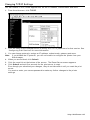
Updating Firmware
You can update the printer’s firmware from your Web browser by connecting to a TFTP server,
or browsing to the update file on your computer.
1.
From the side menu, click Admin. The Web Admin Configuration screen appears.
4-14 System Administrator’s Guide
2.
Click Update Firmware.
3.
The printer should be connected and ready to receive data.
To update from a TFTP server:
Type the TFTP Server IP address.
Type the relative pathname (relative to your TFTP server). Refer to your TFTP Server’s
documentation for more information about setting up and using the TFTP server.
Note: Depending on your TFTP server, you may only need the filename, not the entire path.
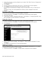
3. Click Submit to load the firmware. If you lose power while updating the firmware, call
Service.
1.
2.
To update from a file on your computer:
Type the location of the file or click Browse and select the file location.
Click Submit to load the firmware. If you lose power while updating the firmware, call
Service.
Note: Do not turn off the printer while it is updating firmware. It may take several minutes to
complete.
1.
2.
Loading the Firmware
Early versions of the software may have menus which differ slightly from those listed below.
1.
2.
3.
4.
Run the UpdateIP utility from the Monarch® Documentation CD-ROM (TC9X00SWP), or
download it from our Web site.
Select the update .bin file, print server, then click Update, Start.
If you are using TCP/IP to upgrade, select TFTP PUT from this host.
If you are upgrading using IPX/SPX on a NetWare network to upgrade, select NetWare GET
from a server (If you are using NetWare to upgrade, you need to put the .bin firmware file in
the LOGIN directory of the NetWare server). Click OK.
If you selected TFTP PUT from this host in step 3, enter the configuration password (default
is access) and click Browse to find the .bin firmware file you downloaded. Click Load. The
firmware on your print server will be upgraded to the new version.
If you selected NetWare GET from a server in step 3, enter the configuration password
(default is access). Enter the name of the NetWare server where you saved the .bin file
as the Host Name. Enter the name of the firmware file for File. Click OK. The firmware
on your print server will be upgraded to the new version.
Using a Web Browser 4-15
Basic Security Configurations
There are two main decisions to be made when choosing wireless security: encryption method
and authentication protocol. The encryption method determines the algorithm used to encrypt
the message. The authentication type specifies how users are identified and verified on a
network. Is the device seeking connection what (and who) it claims to be?
Select an Encryption Method from the following table:
Encryption Method
Type
Algorithm
Size (bits)
Description
WEP
RC4
64/128
This is the 64 or 128 bit WEP Key that must match other nodes’
encryption keys in order to communicate. The user can only
define 10 hex characters (40 bits) for 64 bit WEP or 26
characters (104 bits) for 128 bit WEP.
WPA
RC4
64/128
Improves on WEP by using TKIP* (Temporal Key Integrity
Protocol), which dynamically changes the encryption key and
MIC (Message Integrity Code), which replaces CRC.
WPA2
AES
128
Improves on WPA by replacing RC4 with AES (Advanced
Encryption Standard) for encryption. The user can only define
26 characters (104 bits) for 128 bit
WPA2.
*
Dynamic WEP cannot be selected directly, so select 128 for the encryption mode and select an
authentication mode from one of the following: LEAP, PEAP, EAP-FAST, TLS, or TTLS.
Authentication Protocol
RADIUS Server User ID &
Protocol
Password
Type
Enterprise
LEAP
PEAP*
TLS
Certificate
No
PAP or
MSCHAPv2
Required
Optional*
Required*
N/A
EAP-FAST
PSK
N/A
N/A
TTLS
Personal
Private Key Info File
PAC*
N/A
N/A
*PEAP
This is only for server-side certificates.
*Optional
Leaving the Certificate Root Key and the Certificate CN (common) names blank, no
validation of the host certificate is performed. The values are set to “null” and all host
certificates are accepted.
*Required
The Print Server comes with a default Private Key Information File. You can
either download that file from the print server and add it to the TLS
authentication server, or overwrite a new one on the print server.
*PAC
EAP-FAST does not use certificates to authenticate, but a PAC (Protected
Access Credential), which is managed dynamically by the server. The PAC is
distributed one at a time to the client manually or automatically.
EAP-FAST has an optional feature called "auto-provisioning", which allows a
client to receive the original PAC file wirelessly from the authentication server.
However, this method is less secure and is not supported by Monarch portable
printers.
4-16 System Administrator’s Guide
See the following table of acceptable combinations:
Encryption
Authentication
Open
Shared
WEP
WPA, WPA (TKIP), WPA2
Static
No
Dynamic
Yes
PSK
LEAP
PEAP
EAP-FAST
TLS*
TTLS
*
Load the local key before enabling TLS.
Using a Web Browser 4-17
4-18 System Administrator’s Guide
5
USING THE SIERRA SPORT
C O N F I G U R AT O R
Use the Sierra Sport™ Configurator (SSC) with the Wavelink Avalanche Management
Console software and a Monarch 9460 printer (version 3.0 or greater firmware and version 1.4
or higher boot loader. Purchase the Avalanche software package from the Wavelink
Corporation. Use Avalanche to manage mobile devices over networks (WAN or LAN).
Note: The Monarch 9493 printer does not support Avalanche at this time.
There are several key elements in the Avalanche System:
♦ Avalanche
Enabler
The 9460 printer has a built-in Avalanche Enabler that allows
communications between the printer and the Avalanche agent once the
printer is turned on. You can easily update the printer’s firmware or
configuration and receive status updates from the printer. Use Telnet
console commands to disable the enabler, if necessary. The printer (with
the enabler) is also referred to as a “client.”
♦ Avalanche
Agent
The agent manages functions on the network (WAN or LAN) and stores
the settings and software for the clients. You can have one or more
agents throughout your network. The agent receives commands issued
by the Management Console.
♦ Avalanche
Management
Console
Use the Management Console to issue commands to the agents. Your
System Administrator can view and manage all agents and clients on the
network by scheduling updates, identifying client settings, configuring
profiles, and checking the status (failure/success) of updates to each
client on the network.
Download our .AVA package (SSCfg.AVA) from our Web site. The package contains all the files
you need to connect with Avalanche including the SSC software.
For information about using the Avalanche Management Console, refer to your Avalanche
documentation. The following graphic shows how Avalanche works with the 9460 printer.
Files are transferred from the console to the agent through the WAN or LAN and onto the
clients.
Ava lanche Manager Age nt
Console w ith
Sierra Sport
Configurator
loaded
Ava lanche-Enabled
Clients (Printers)
Using the Sierra Sport Configurator 5-1
System Requirements
To use the Avalanche-enabled printer, you need the following:
♦ the Wavelink Avalanche Manager Agent (version 3.6.3 or greater) and Console (version 3.6.0
or greater)
♦ the AVA package (SSCfg.AVA)
♦ a wireless network
Before You Begin
1.
2.
3.
4.
5.
6.
7.
Install the Avalanche Manager Agent and Console.
Open the Manager Agent.
Open the Avalanche Management Console.
Connect the Management Console to the agent.
Install the software package (SSCfg.AVA).
Select Configure Utility.
Click Configure Package to start the Sierra Sport Configurator.
When the application begins, the most recently-used session opens if one exists.
Otherwise, a new session begins.
When the printer is turned on, it appears in the Avalanche Management Console as a
client. Use the console to schedule the updates (new files or firmware) for each printer
(client). Depending on your application, this could be done once a day or every time the
printer is turned on.
Changing the Avalanche Directory
You need to specify the directory where Avalanche is installed, if the application does not
automatically find it for you.
1.
2.
3.
Select Options from the File menu.
Browse to the directory and select OK.
Click OK to return to the application.
You see the Wireless Settings tab.
Use the following instructions to configure the print server.
5-2 System Administrator’s Guide
Configuring Wireless Settings
Use this tab to configure the wireless settings.
1.
2.
Specify the Basic Wireless settings including Mode, Radio, SSID, Channel, Speed, Access
Point Density, International Roaming, Dynamic Frequency, Country and RTS Threshold.
Specify the Wireless Security and enter any WEP Keys, Wireless Authentication, or
Passwords as required.
Configuring the Extended Security Settings
Use this tab to configure the extended security settings.
Specify the Certificate settings, including the Root Key, Common Names, Organization
Names, and Passphrases as required.
Configuring the Print Server Settings
Use this tab to configure the server settings.
1.
2.
3.
4.
5.
Specify the basic Print Server settings including the System Name, Location, SNMP
Community Name, and Power Level as required.
Enable Restart the Network Interface to reinitialize the print server with the selected
settings at the end of the script.
Enable Restore Default Configuration to restore all print server defaults before applying
any other configuration settings.
Enter the Passwords for Read and Write Access.
Enter the Firmware Update File and TFTP Server IP Address if necessary.
Configuring Services
Use this tab to configure the services for TCP/IP and NetWare.
1.
2.
3.
Enter the Service Settings including the Filter, Priority, and TCP Port.
Select the Protocol and NetWare Queue Server or Remote Server.
Specify the Control Strings for the Beginning and End of Jobs.
Using the Sierra Sport Configurator 5-3
Configuring TCP/IP Settings
Use this tab to configure the TCP/IP settings.
1.
2.
3.
Enter the various TCP/IP settings including IP Address, Subnet Mask, Gateway, Boot
Method, Boot Tries, and Timeouts as required.
Select any LPD or RARP settings.
Enter the DNS settings.
Specifying the IP Access Range
Use this tab to specify a range of acceptable IP addresses and Subnet Masks.
1.
Click <<Add.
2.
3.
4.
5.
Enter the Starting Address.
Enter the Ending Address.
Click OK when finished.
Click Add>> to enter the Starting Address and Ending Address for
the Subnet Mask.
Click OK when finished.
6.
Configuring Printranet Settings
Use this tab to configure the Printranet settings including POP3 and SMTP.
Configuring NetWare Settings
Use this tab to configure the NetWare settings including Frame Type, Password, and
Configure Bindery File Servers.
5-4 System Administrator’s Guide
Setting Alerts and Traps
Use this tab to configure the email alerts and SNMP IP Traps.
1.
2.
Specify the Email Alerts, including the SMTP Server Address, SMTP Server Port, enter the
Email Address and select the Trigger Conditions for each email address.
Specify the SNMP IP Traps including the Trap Community. Enter the IP Address and IP
Port. Select the Trigger Conditions for each IP address.
Configuring Printing Settings
Use this tab to configure the printer’s supply settings, regional settings, and image adjustments.
1.
2.
3.
Enter any Supply Setup information including Ribbon/Energy, Supply Type, Feed Mode,
and Supply Position.
Enter any Image Adjustments including Contrast, Print Position, and Margin Position.
Enter any Regional Settings including Symbol Set, Currency Symbol, Decimal Places,
Secondary Currency Symbol, and whether to print a Slashed Zero.
Using the Sierra Sport Configurator 5-5
Updating Files
Use this tab to update the printer’s firmware or print server’s firmware. Select additional MPCL
files to send to the printer (fonts, graphics, etc.).
1.
2.
3.
4.
Select the binary Firmware File to Load.
Select the Monarch Initialization File (.mif) to Load.
Select the Print Server Firmware File to Load.
Enter any Printer Accessory Files to Load, including formats, fonts, graphics, check digits,
etc.
Saving Changes
1.
2.
When you are done specifying the print server’s settings, select Write Configuration from
the File menu.
Exit the Sierra Sport Configurator.
The print server’s configuration is set and ready for Avalanche to send to the printer.
3.
Using the Avalanche Management Console, highlight the client and click Update Now,
which updates the client immediately, instead of waiting until the scheduled time.
Creating Your Own Packages
We created the AVA package (SSCfg.AVA) to easily configure the print server and send
updates to the printer. If you just need to update firmware, you can create your own package.
1.
Use the Avalanche Package Builder to set up packages since everything is transferred to
the printers via a package.
You may want to create separate packages for printer firmware updates or print server
firmware update.
5-6 System Administrator’s Guide
Packages include the following list of file extensions:
Extension
Description
.bin
Print Engine Firmware
.mif
Standard Monarch .mif file (Monarch Initialization file)
.pcl
MPCL data
.psb
Print Server Binary
.psc
Print Server Configuration Script
.asc
Authentication Server Certificate
.lcc
Local Client Certificate
2.
Install the package.
Using the Avalanche Management Console, select the package, enable the package and then,
send the package.
Using the Sierra Sport Configurator 5-7
5-8 System Administrator’s Guide
6
TELNET CONSOLE COMMANDS
Use this chapter to configure the print server using Telnet.
You must have a basic understanding of Telnet commands. For initial setup, do not use Telnet.
Use auto-discover mode. Once you have the IP address, you can use Telnet or a Web browser.
You can use Telnet if you do not have access to the NetManager software.
Note:
The default port is Port 23.
To access Telnet console mode:
1.
2.
3.
Start Telnet.
Press Enter (on your host) until you see the “#” prompt.
Type access as the password and press Enter. (access is the default password.)
4. Press Enter to by-pass the user name. You do not need to enter a username.
Note:
The Telnet session times out after 10 minutes of inactivity.
Conventions
This section uses the following conventions:
KEYwords
Type the capitalized letters of each keyword instead of the whole keyword.
Some keywords require more capitalized letters than others. For example,
SEt
KEYVAL
RAdio
[options]
Mutually-exclusive options are included within square brackets and
separated by a forward slash. Select only ONE of the options. For
example, [DISable/STRICT/FLEXible]
<values>
Values are included within brackets. Values that contain spaces (multiple
words) must be enclosed within quotation marks (""). For example,
SEt NW PW <value>
SEt NW PW "Store 876"
n
Numeric digits are indicated by the letter (n). For example,
SEt IP BOot n
SEt IP BOot 5
SEt NW CHannel nn
SEt NW CHannel 11
Settings
1.
To view the current wireless settings, type sh nw (show network settings) and press Enter:
WiFi Mode = INFRASTRUCTURE
WiFi SSID: ABC1234
Speed = 54
International Roaming: Flexible
Dynamic Frequency Selection: Unsupported
Regulatory Domain = USI
WiFi FW Ver = 2.13.10.0 LMAC, 2.12.18.0 UMAC
AP density = LOW
Authentication type= OPEN SYSTEM
Encryption is Disabled
Local certificate loaded
AP MAC Address = 00 A0 F8 51 B4 FC
Signal Quality = Excellent (100%)
Connected to SSID ENG4121 on channel 11
Telnet Console Commands 6-1
2.
To show the current IP settings, type sh ip (show TCP/IP settings) and
press Enter.
IP is enabled
IP address
Subnet mask
IP Router
(via DHCP
LPD banner
LPD retries are
Service
PXR1E8580_X1
3.
192.0.0.192
Boot tries
3
255.255.0.0
Boot method
AUTO
192.0.0.192
Max window
10240
192.0.0.192)
disabled
Timeout
0 min
disabled
Keepalive
1 min
Port
TCP port
X1
9100
To show the current Avalanche settings, type sh ava (show all Avalanche properties) and
press Enter.
Console IP address: 192.0.0.192
Avalanche is Enabled
Packages installed:
SSCfg: Revision 1
Properties set:
OsVer = 3.0
OsType = PHG2
ProcessorType = MC68336GCAB20
ProcessorRevision = 1F76K
Processor = freescale
Type = M09460
ModelCode = 22
ModelName = PXR1E859E
NetVer = 1.14
EnablerVer = 1.63
RadioType = G
CoreEnabler = 3
4.
5.
6.
7.
8.
To change the SSID, type set nw ssid testsystem and press Enter.
To set the IP address, type set ip ad 192.0.0.192 and press Enter.
To set the subnet mask, type set ip sub 255.255.255.0 and press Enter.
Type INIT and press Enter to save the settings and initialize the unit.
Type EXIT to exit Telnet.
Help Commands
For help at any time, type “Help” and a list of available commands appears. The Help command
builds on itself, because for each command you type, more details appear for each option.
Syntax:
help set
DEFAULT
PAssword <password>
POrt <name> ...
NWrk
PROtect <password>
SERVEr
SERVIce
<name>
SNMP
Avalanche
POWer
SYSLog
DNS
STRing n "..."
IP
POP3
SMTP
NETWare
POWERON <delay-sec>
Set parameters to factory defaults
Set console password
Parameter for port <name>
Network Parameters
Set update password
Server Parameters
Service Parameters
SNMP Variables
Avalanche Parameters
Power Management
Syslog Parameters
DNS Parameters
BOT/EOT string
LPD/TCP Parameters
POP3 Parameters
SMTP Parameters
Netware Parameters
Power on delay
Displays a list of the available help commands for “Set.”
Note: For any command that uses SET, you can also use SHOW to view the current setting.
6-2 System Administrator’s Guide
Syntax:
help set ip
IP
LPD/TCP Parameters
Access [EN/DIS] aa.bb.cc.dd {Mask ee.ff.gg.hh}
ADdress aa.bb.cc.dd IP node address
ARP
[EN/DIS]
IP set via ARP
BAnner [EN/DIS]
LPD banner printing
CHKSUM [EN/DIS]
IP receive checksum
BOot
n
Number of DHCP/BOOTP tries
ECHO
[EN/DIS]
TCP echo protocol
ENable/DISable
Enable or Disable IP Processing
FTIme [EN/DIS]
Timeout in seconds if enabled
FTP
[EN/DIS]
FTP protocol
HTTP
[EN/DIS]
HTTP protocol
HTTPS [EN/DIS]
HTTPS protocol
KEepalive n
Keepalive interval (min)
LPD
[EN/DIS]
LPD protocol
MEthod <type>
Set method of getting IP address
PIng
aa.bb.cc.dd Test connection to IP host
PRObe [EN/DIS]
TCP connection probes
RANge [EN/ALL] aa.bb.cc.dd [MAx ee.ff.gg.hh]
RARp flags nn
1=no subnet, 2=no router, 3=neither
REtry [EN/DIS]
LPD retry continuation
ROuter aa.bb.cc.dd Default router address
SUbnet aa.bb.cc.dd Subnet mask
STELnet [EN/DIS]
S-TELNET protocol
TCP
[EN/DIS]
Raw TCP (9100) protocol
TELnet [EN/DIS]
TELNET protocol
TFTP
[EN/DIS]
TFTP protocol
TImeout n
Inactivity timeout
TRAP n [ADDR/PORT/TRIG]
TRAP configuration
WIndow nn
LPD/TCP maximum window size
Displays a list of the available help commands for “Set IP.”
General Commands
From the list of commands, the brackets - [] indicate to pick one of the options listed.
CLear/DELete/PUrge
Removes a specified parameter or configuration item.
CLear FATal
Deletes fatal error log.
CLear POrt <portname> JOB
Clears current entry in the print server's internal queue for the specified portname (P1 for the first
parallel port).
CLear PROTECT
Sets the update password to “null.”
CLear SERVEr STRing n
Removes BOT/EOT string.
EXIT/^D
Exits console mode.
HElp
Displays the list of available commands.
INitialize
Saves settings and resets unit.
Telnet Console Commands 6-3
SAVE
Saves configuration settings.
CHange/SEt/DEFine
Sets configuration items.
SEt DEFAULT
Sets print server to factory defaults.
SEt LOAd [EN/DIS]
Enables or disables firmware reload after exit.
SEt LOAd HOst <name>
Sets node name of boot host (NetWare firmware load).
SEt LOAd IP aa.bb.cc.dd
Sets IP address of load host (TCP/IP firmware load).
SEt LOAd SOftware <filename>
Sets print server’s firmware filename to load.
SEt PAssword
Sets console password. The default password is access.
Note:
The password is case-sensitive.
SEt PROtect <password>
Sets the update password.
SEt SERVEr DEScription
Sets mode description to string displayed with SHOW SERVER command.
SEt SERVEr NAme <name>
Sets server node name.
SEt SERVEr SYSLog [EN/DIS]
Enables or disables access to the system log.
SHow FATal
Shows the fatal error log.
SHow FREE
Shows the amount of available memory.
SHow LOAd
Shows the print server’s firmware update parameters.
SHow SERVEr
Shows the server parameters.
SHow SERVEr COunters
Shows the server statistics.
SHow SERVEr QUeue
Shows the print server internal queue.
SHow SERVEr SYSLog
Shows the system log, if access is enabled.
SHow TEstpage
Prints a test page.
SHow VErsion
Shows the server firmware version.
6-4 System Administrator’s Guide
UNPROTect
Allows the user to enter the update password (if one has been defined). Once the update password is
entered correctly, SET commands can be used to modify the configuration until the console session is
closed with EXIT.
ZEro
Zeros statistical counts.
Avalanche Console Commands
DELete AVAlanche PROPerty <name>
Removes an Avalanche property.
Note:
This allows the user to delete system-defined properties. However, they are recreated
on a restart.
SEt AVAlanche IP <ip address>
Sets the address of the Avalanche Agent.
SEt AVAlanche <EN/DIS>
Enables or disables the Avalanche Enabler.
SEt AVAlanche PROPerty <name> <property value>
Adds an Avalanche property.
Port Commands
SEt POrt <name>
Sets the name of the communications port.
SHow POrt <name> STA
Shows the current port status.
802.11b/g Wireless Commands
CLear NW SSid
Clears the SSID, so the server connects to any access point.
SEt NW APDEN [LOW/MED/HI]
Sets 802.11b/g access point density.
SEt NW AUTHTRY n
Specifies the number of authentication tries the user is given.
SEt NW AUTHtype [OPEN/SHARED/TLS/TTLS/LEAP/PEAP/
EAP-FAST/PSK]
Sets the authentication type. See Chapter 4, “Using a Web Browser” for more information.
SEt NW CERTCN <name>
Sets the EAP common name. If no value is set (null), all host certificates are accepted.
SEt NW CERTCN2 <name>
Sets the second EAP common name. If no value is set (null), all host certificates are accepted.
SEt NW CERTEXP <value>
Sets the EAP certificate exponent value.
SEt NW CERTKEY <keyvalue>
Sets the EAP root key value.
SEt NW CHannel nn
Sets 802.11b/g wireless channel.
SEt NW ENC [DIsable/64/128/WPA/WPA2/WPA2-WPA]
Sets the encryption mode. See Chapter 4, “Using a Web Browser” for more information.
Telnet Console Commands 6-5
SEt NW ID <userID>
Sets the authentication user ID. It may include the realm, separated with the at (“@”) character.
Country
Code
Description
Country
Code
Description
Country
Code
Description
AL
ALBANIA
HN
HONDURAS
PS
PALESTINIAN TERRITORY
DZ
ALGERIA
HK
HONG KONG
PA
PANAMA
AR
ARGENTINA
HU
HUNGARY
PS
PALESTINIAN TERRITORY
AM
ARMENIA
IS
ICELAND
PE
PERU
AT
AUSTRIA
IN
INDIA
PL
POLAND
AU
AUSTRALIA
ID
INDONESIA
PH
PHILIPPINES
AZ
AZERBAIJAN
IR
IRAN, ISLAMIC REPUBLIC OF
PT
PORTUGAL
BH
BAHRAIN
IE
IRELAND
PR
PUERTO RICO
BY
BELARUS
IL
ISRAEL
QA
QATAR
BE
BELGIUM
IT
ITALY
RO
ROMANIA
BZ
BELIZE
JP
JAPAN
RU
RUSSIAN FEDERATION
BO
BOLIVIA
JO
JORDAN
SA
SAUDI ARABIA
BA
BOSNIA AND HERZEGOVINA
KZ
KAZAKHSTAN
SG
SINGAPORE
BR
BRAZIL
KE
KENYA
SK
SLOVAKIA
BN
BRUNEI DARUSSALAM
KP
KOREA, PEOPLE'S REPUBLIC
SI
SLOVENIA
BG
BULGARIA
KR
KOREA, REPUBLIC
ZA
SOUTH AFRICA
CA
CANADA
KW
KUWAIT
ES
SPAIN
CL
CHILE
LV
LATVIA
LK
SRI LANKA
CN
CHINA
LB
LEBANON
SE
SWEDEN
CO
COLUMBIA
LI
LIECHTENSTEIN
CH
SWITZERLAND
CR
COSTA RICA
LT
LITHUANIA
SY
SYRIAN ARAB REPUBLIC
HR
CROATIA
LU
LUXEMBOURG
TW
TAIWAN
CY
CYPRUS
MO
MACAO
TH
THAILAND
CZ
CZECH REPUBLIC
MK
MACEDONIA
TT
TRINIDAD AND TOBAGO
DK
DENMARK
MY
MALAYSIA
TN
TUNISIA
DO
DOMINICAN REPUBLIC
MT
MALTA
TR
TURKEY
EC
ECUADOR
MX
MEXICO
UA
UKRAINE
EG
EGYPT
MC
MONACO
AE
UNITED ARAB EMIRATES
SV
EL SALVADOR
MA
MOROCCO
GB
UNITED KINGDOM
EE
ESTONIA
NA
NAMIBIA
US
UNITED STATES
FI
FINLAND
NL
NETHERLANDS
UY
URUGUAY
FR
FRANCE
NZ
NEW ZEALAND
UZ
UZBEKISTAN
GE
GEORGIA
NO
NORWAY
VE
VENEZUELA
DE
GERMANY
OM
OMAN
VN
VIETNAM
GR
GREECE
PK
PAKISTAN
YE
YEMEN
GT
GUATEMALA
HK
HONG KONG
ZW
ZIMBABWE
6-6 System Administrator’s Guide
SEt NW INAP [PAP/MSCHAP_V2]
Sets the EAP inner authentication protocol.
SEt NW IROAM [DISable/STRICT/FLEXible]
Controls whether the radio frequencies are set based on the radio configuration or from its access point.
Disabled uses the radio defaults. Flexible uses access point settings if present, otherwise the radio
defaults are used. Strict uses access point regulatory frequency information.
SEt NW KEY# <1/2/3/4>
Sets which WEP key number to use (default is 1).
SEt NW KEYVAL <WEPkey>
Sets WEP key value. Must be hexadecimal.
SEt NW MOde [INfra/ADhoc]
Sets 802.11b/g wireless mode to infrastructure or Ad-Hoc mode.
SEt NW PW <password>
Sets the password for 802.11b/g EAP authentication.
SEt NW REALM <realm>
Sets the realm portion of the 802.11b/g EAP authentication ID.
SEt NW RTS n
Sets the network RTS threshold. Range is 1-3000.
SEt NW REGDOMain <countrycode>
Sets the region of operation for the print server using the following table. The list of supported
countries varies based on the radio type (802.11b or 802.11b/g).
SEt NW SPeed <1/2/5.5/6/9/11/12/18/24/36/48/54>
Sets 802.11b/g wireless speed in megabits per second (Mpbs).
SEt NW SSid “<ssid>”
Sets 802.11b/g wireless SSID. Use quotes if there is a space in SSID. This is case sensitive.
SH NW STATS
Shows the network I/O statistics.
SEt NW WEP [DIS/64/128]
Sets wired equivalent privacy encryption level to disabled, 64-bit, or 128-bit.
SEt NW WPAGROUP [ENABLE/DISABLE]
Selects whether to use the WPA group key mode. When enabled, group keys are used for data link
encryption.
SEt NW WPAPSK <psk-str>
Sets the WPA pre-shared key or pass-phrase. Use 64 hex characters for the PSK or 8-63 characters for
the pass-phrase. This is only valid when authentication mode is WPA-PSK.
TCP/IP Commands
SEt IP [EN/DIS]
Selects whether to use IP-based protocols.
SEt IP ACcess [EN] aa.bb.cc.dd
[Mask ee.ff.gg.hh]
Allows or prevents specified IP address from accessing print server.
SEt IP ADdress
Sets IP address of print server.
SEt IP ARP [EN/DIS]
Selects whether to use an IP address with an ARP packet.
Telnet Console Commands 6-7
SEt IP BAnner [EN/DIS]
Sets printing of LPD job banners.
SEt IP BOot n
Sets number of retries (n) for DHCP, BOOTP, RARP
SEt IP CHKSUM [EN/DIS]
Enables or disables IP receive checksum.
SEt IP FTIme [EN/DIS]
Enables or disables fast timeout.
SEt IP FTP [EN/DIS]
Selects whether to use the FTP protocol.
SEt IP HTTP [EN/DIS]
Selects whether to use the HTTP protocol.
SEt IP KEepalive n
Sets keep alive interval (n) in minutes.
SEt IP LPD [EN/DIS]
Selects whether to use the LPD protocol.
SEt IP MEthod [AUTO/BOOTP/RARP/DHCP/STATIC]
Sets method of getting IP address.
SEt IP PIng aa.bb.cc.dd
Sends IP ping packets to test the host connection.
SEt IP PRObe [EN/DIS]
Enables or disables the TCP connection probe.
SEt IP RARp flags nn
0 Both
1 no subnet
2 no router
3 neither
Default (0) - IP address is set with subnet mask and router that is the same address as host.
SEt IP RANge [EN/DIS/ALL] aa.bb.cc.dd [MAx ee.ff.gg.hh]
Sets the valid range of IP addresses.
SEt IP REtry [EN/DIS]
Enables or disables LPD retry continuation
SEt IP ROuter aa.bb.cc.dd
Sets default Router/Gateway address (or access point).
SEt IP SUbnet aa.bb.cc.dd
Sets default subnet mask.
SEt IP TCP [EN/DIS]
Selects whether to use the raw TCP (port 9100) protocol.
SEt IP TELNET [EN/DIS]
Selects whether to use the Telnet protocol.
SEt IP TFTP [EN/DIS]
Selects whether to use the TFTP protocol.
SEt IP TImeout n
Sets timeout (n) in minutes.
SEt IP TRAP n ADDR <a.b.c.d[:e]>
Sets the destination IP address and optional port number to specify where to send the trap (n). If the
port is not specified, it defaults to 162.
6-8 System Administrator’s Guide
SEt IP TRAP n POrt n
Specifies the port that will be scanned for trigger conditions. The parameter is a bit mask.
SEt IP TRAP n TRIGger cccc
Specifies the trigger conditions (cccc) that send a trap (n). The parameter is a
bit mask.
1
On line
2
Off line
4
(not used)
10
Paper out
20
Paper jam
8000 Printer error
SEt IP WIndow nn
Sets the LPD/TCP maximum window size (nn).
SNMP Commands
CLear SNMP CONtact <string>
Removes SNMP SysContact.
CLear SNMP LOCation <string>
Removes SNMP SysLocation.
SEt SNMP CONtact
<string>
Sets SNMP SysContact.
SEt SNMP LOCation <string>
Sets SNMP SysLocation.
SEt SNMP GETCOMM
<string>
Gets SNMP community.
SEt SNMP JETADmin [EN|DIS]
Selects whether to use the JetAdmin protocol.
SEt SNMP SETCOMM1 <string> or SET SNMP SETCOMM2 <string>
Sets SNMP community 1 or community 2 name.
Note:
An incoming set request can use either name for comm1 or comm2.
SEt SNMP TRAPCOMM <string>
Sets SNMP trap community name.
Telnet Console Commands 6-9
6-10 System Administrator’s Guide
7
TROUBLESHOOTING
Verify that the printer is operating properly, is online, and supplies are loaded
correctly.
General Troubleshooting Information
Use the following information if your print server is not operating properly.
1.
2.
Verify that the printer is turned on.
Verify the print server is connected to the network.
The 9460 printer’s display shows the <T> symbol when the printer is connected and
ready to receive data.
The 9493 printer’s display shows the M or the n symbol when the printer is connected
and ready to receive data.
3.
Print a test label. See Chapter 2, “Configuring the 802.11b/g and IP Settings” for more
information.
Use 2-inch supply or some information may print off the label.
If a label does not print, check the printer's display to see if it shows a receiving status.
Turn off the printer, wait fifteen seconds and then turn it back on.
4.
On the test label, verify your IP and wireless settings.
Check the “Actual SSID” and the “Sig Strength”. Is the actual SSID correct? Is the
signal quality greater than zero? If the signal quality is 0, you lost connection with the
access point. If it is very low, you may be experiencing interference or are very close to
being out of range or an access point. A value of 100 is the best you can have for
signal quality. You can probably operate at a minimum of 60, but the number of retries
is likely to increase.
5. Telnet to the printer.
Note: After the print server has been reset, you may need to re-enable Telnet, or connect
serially.
Once you have verified connectivity, Telnet to the printer. This gives you access to
console operation of the printer. Press Enter (on your host) and enter access as the
password. Press Enter to by-pass the user name. Once here, you have verified
operation to the print server.
6.
Ping the printer.
Pinging the printer tells you if it is “seen” on the network. If you cannot ping the printer, turn
the printer off and then on. Then ping every device in the path to the printer - access points,
routers, etc. Any device you cannot ping needs attention.
ping <ip address>
7.
(i.e.
ping 192.0.0.192)
Verify connection to the data port by starting a Telnet session to the printer using port 9100
(i.e. Telnet aa.bb.cc.dd 9100).
Press Ctrl-E on your keyboard. This sends an ENQ request. The printer responds with
three characters. Depending upon the Telnet being used, you may not see the first
character, as it is a hex 05 value. The other two characters are ASCII characters.
You see
A@
which means the printer is online and waiting. Alternatively, you can type
[J,2]
Note:
The J must be capital.
Troubleshooting 7-1
The printer responds with {J,0,0,””,””} .
No response means that the printer may have an open session to some other
connection. Either terminate the other connection or turn off the printer and turn it back
on.
Troubleshooting Wireless Configuration Problems
1.
Your computer’s wireless adapter and/or access point should be configured to match your
print server.
2. The printer should be within range (up to 90 meters or 300 feet) of your computer and away
from metal objects and other devices with radio signals (Bluetooth®, 2.4 GHz cordless
phones, and microwaves).
3. Use infrastructure mode to connect through an access point. Use Ad-Hoc mode to connect
without an access point.
4. To use WEP (Wired Equivalent Privacy) or other advanced security on your wireless
network, temporarily disable the security on your computer in order to configure the print
server. You may need to temporarily change the wireless mode of your computer to Ad-Hoc
(802.11) mode to allow non-secure clients to communicate with each other.
Note: You many need to temporarily disable the security on your access point to set your
computer to Ad-Hoc mode. When you are done configuring the print server, you can reenable the security on your computer and change the wireless mode back if necessary.
You can also use a serial (wired) connection to configure the print server.
5. To use encryption or password protect your wireless network, and your wireless adapter or
access point normally uses a password or passphrase instead of WEP, it should allow you
to enter 0x followed by a ten digit (for 40-bit or 64-bit WEP) or twenty-six digit (for 128-bit
WEP) key in hexadecimal format (0-9 or A-F).
6. Change the RF channel (Ad-Hoc mode only) to correct intermittent connection problems or
slow performance. This can be done in the NetManager Wireless Configuration screen.
Change it to at least 3 channels lower or higher than any other wireless networks within
range.
Troubleshooting Network Configuration
♦ To use TCP/IP, your computer and the print server should be on the same IP segment or can
reach each other with a PING command from the host. The IP address you assign to the print
server must be on the same logical network as your host computers.
♦ If your print server is set to Auto or DHCP for obtaining an IP address, the print server’s IP
address can change. Either configure your DHCP server to give the print server a permanent
lease or configure the print server to be on a static address that does not conflict with any
other address.
Technical Support
If these solutions do not work, call Service at the number listed on the back of this manual.
7-2 System Administrator’s Guide
S P E C I F I C AT I O N S
Link Layer:
802.11b/g
Protocols:
TCP/IP
Passthru
BOOTP
DHCP
RARP
LPD/LPR
Telnet
RSH or REMSH (remote shell)
FTP
SNMP
NetWare
HP Jet Admin
A
802.3 Specifications (9493™ only)
Communication
Rate:
10 Mbps or 100 Mbps
802.11b/g Specifications
Frequency:
2.4 GHz range, direct sequence
Communication Rate:
1, 2, 5.5, or 11, 12, 18, 24, 36, 48, or 54 Mbps
Channels
1 to 11
Mode:
Ad-Hoc or infrastructure
Encryption:
WEP 64 or WEP 128
WPA or WPA2
Authentication:
EAP-FAST
LEAP
PEAP
TLS
TTLS
PSK
Specifications A-1
A-2 System Administrator’s Guide
GLOSSARY
Absolute Pathname
Access Point
Ad-Hoc
Netw ork/Mode
Authentication
Method
Auto Method
BOOTP or
Bootstrap Protocol
Boot Method
Boot Tries
BSS or
Basic Service Set
BSSID
Channel or
RF Channel
DHCP or
Dynamic Host
Configuration
Protocol
EAP (Extensible
Authentication
Protocol)
FAST (Flexible
Authentication via
Secure Tunneling)
Gatew ay
Infrastructure
Mode
IP Address
LAN or
Local Area
Netw ork
G
The full path of a file, including the computer system and any directories or
subdirectories. For example,
c:\program files\monarch softw are\mpcl toolbox\9460.phu
An interface between a wireless network and a wired network. Access points can be
used with Ethernet or other communications to enable roaming throughout a facility.
A wireless network composed of devices that contain a network interface card and no
access point.
Ad-Hoc mode is also called peer-to-peer (point-to-point) communications or BSS
network. As long as the devices are in range and are on the same channel and SSID,
they connect and communicate. Use this mode if a wireless infrastructure does not
exist or where services are not required.
Identifies users on a network, based on a username and password. There are two
types: open and shared. Authentication protocols include LEAP, PEAP, TLS, TTLS,
EAP-FAST, and PSK.
One of the available boot methods. Auto tries DHCP, BOOTP, and RARP, then sets to
the last IP address used if the IP address is not automatically set using any of the
previous methods.
One of the available boot methods. It is a protocol used by devices that know their
MAC address, but do not know their IP address. The device broadcasts its hardware
address and the BOOTP server responds with the IP address for it. The network
administrator must enter the MAC address in the BOOTP Config file to obtain the IP
address from the server.
The wireless print server uses this method to obtain an IP address. Can be set to Auto,
DHCP, BOOTP, RARP, or Static.
The number of times the device tries to get an IP address from the server when using
the BOOTP and DHCP methods.
A set of 802.11b/g devices operating as a fully connected wireless network.
See MAC Address.
You can select which channel your network devices use to communicate. All devices
must be on the same channel to communicate in Ad-Hoc mode. Other radio devices
such as Bluetooth® wireless devices, microwave ovens, or
2.4-GHz cordless phones may operate/interfere if they are on the same channel as your
network.
One of the available boot methods. It is a protocol that issues IP addresses
automatically within a specified range to devices (such as printers) when they are first
turned on. The device keeps the IP address for a defined period of time set by your
System Administrator; however, a device could have a different IP address every time it
connects to the network.
Defines how to pass authentication information between the device and authentication
server. The authentication is handled by the EAP type: FAST, TLS, TTLS, etc.
Cisco Systems® developed this authentication protocol.
It does not use certificates to authenticate, but a PAC (Protected Access Credential),
which is managed dynamically by the server. The PAC is distributed one at a time to
the client manually or automatically.
Allows connections (communications) between different subnets on a network.
Requires an access point to communicate with other devices on the network. In
infrastructure mode, wireless devices can communicate with each other or with a wired
network.
An Internet Protocol identifier for a device on a network. It consists of four 3-digit
numeric fields, separated by periods. Each number can be zero to 255. An IP address
has two components, the network address and the host address. Most company
networks have ranges for their IP addresses.
A computer network that connects personal computers, workstations, servers, and
printers. This allows each user on the network the ability to share devices, such as
printers, and communicate with each other via email, etc. LANs can be connected to
each other by telephone lines or radio waves. See WLAN.
Glossary G-1
LEAP (Lightw eight
Extensible
Authentication
Protocol)
LPD/LPR
MAC Address or
Media Access
Control
MSCHAPv2
(Challenge
Handshake
Authentication
Protocol)
NIC or
Netw ork Interface
Card
Node
Open Authentication
PAP (Password
Authentication
Protocol)
Pathname
PEAP (Protected
Extensible
Authentication
Protocol)
Ping
Protocol
PSK
(Pre-Shared Key)
RADIUS (Remote
Authentication DialIn Server)
RARP or
Reverse Address
Resolution Protocol
Relative
Pathname
Router
Shared
Authentication
Cisco Systems® introduced this authentication protocol and provides mutual
authentication with unique WEP keys for each user. New keys are issued based on a
time limit. Changing the WEP key time limits provides additional security.
A printer protocol that uses TCP/IP to establish connections between printers on a
network. Also known as Line Printer Daemon/Line Printer Remote.
A hardware address (6-byte) that uniquely identifies each node of a network. The MAC
address is set during manufacturing and does not change. Also, two Network Interface
Cards (NIC) will not have the same value.
The Microsoft® version of CHAP. It is a three-way handshake protocol that is more
secure than PAP.
It provides mutual authentication between devices.
An adapter (board or card) that can be inserted into a device, so the device can be
connected to a network.
The NIC converts data from the device into the form transmitted or received from the
network
A processing location on a network. The location can be a workstation, computer, or
printer. Each Node has a unique MAC address.
This allows any device to authenticate and then attempt to communicate with the
access point. Any wireless device can authenticate with the access point, but if WEP is
used, the device can communicate only if its WEP keys match the access point's.
There is no challenge that occurs, you either have the correct key or not when you
communicate with the access point. By eliminating the challenge process, it actually
makes this more secure than shared key authentication.
A simple authentication protocol used with PPP (Point-to-Point Protocol). It is a plain
text password system, which is not very secure.
The location of a particular file or directory that includes the full path to the needed
filename or directory. This is a combination of path and filename.
Authenticates clients into a network using only server-side certificates, which makes
implementing and administering a wireless LAN easier.
A way to determine if a device is accessible. It sends a packet to the specified address
and waits for a reply.
This is the way two devices transmit data between each other, including error checking,
data compression, and how messages start and end.
Authentication mode of WPA used in SOHO environments. The key value (or passphrase) is used for network authentication only (not data encryption). It does not use a
RADIUS server like the other modes, but uses a shared key to provide the initial
authentication with the access point or host.
This is an authentication server, such as the Cisco® ACS, Microsoft® IAS, etc.
One of the available boot methods. The device sends an RARP request and the RARP
server responds with an IP address. The device knows its MAC address and the server
responds with the IP address for it.
The file or directory location on the user’s system relative to the user’s current location
on the system (what directory the user is currently in). For example, c:\\program files\
monarch softw are\mpcl toolbox\9460.phu
Any device that forwards data along networks. Routers are located at gateways.
The access point sends an unencrypted challenge text string to any device attempting
to communicate with it.
The device requesting authentication encrypts the challenge text and sends it back to
the access point. If the challenge text is encrypted correctly, the access point allows
the requesting device to authenticate. Both the unencrypted challenge and the
encrypted challenge can be monitored; however, this leaves the access point open to
attack. Because of this weakness, shared key authentication can be less secure than
open authentication.
G-2 System Administrator’s Guide
Signal Strength
Speed or
Transmit Rate
A percentage (1 to 100) of the connection between the device and access point. If the
signal strength is 0, there is no connection with the access point; 30 or less indicates
you may be experiencing interference or close to being out of access point range, and
below 50, printing performance could be affected. To improve the signal strength, try
moving the printer closer to the access point and away from other radio devices such as
Bluetooth® wireless devices, microwave ovens, or 2.4-GHz cordless phones.
Sets the maximum rate of communication between the devices on the network. It is
also called transmit rate.
The speeds are in megabits per second (Mbps) and include: 1, 2, 5.5, 11, 12, 18, 24,
36, 48, and 54.
SSID or
Service Set Identifier
A unique identifier that must match for all nodes on a subnetwork to communicate with
each other. It consists of up to 32 characters (any printable character, including
spaces). If using the space character, it must be enclosed in quotation marks. It is
case-sensitive.
Static
Method
One of the available boot methods. Use static if your network uses fixed configuration.
The IP address remains the same every time the device connects to the network.
Subnet
A portion of a network that shares a common address component. On TCP/IP networks,
subnets are all devices with the same prefix. For example, all devices that start with
192.192.192 are part of the same subnet. Dividing a network into subnets is useful for
both security and performance reasons.
Subnet Mask
A mask is used to determine what subnet an IP address belongs to. Companies often
have ranges of IP addresses that can be described by one or more masks. For example,
a mask of 255.255.255.0 allows variation in the last position only, because the first
three positions are fixed.
Telnet
A Terminal Emulation program for TCP/IP networks that runs on your computer and
connects your computer to a server on the network. You enter commands through the
Telnet program and they run as if you were entering them directly on the server
console.
TCP/IP
A way that two devices can transmit data between each other. TCP/IP (Transmission
Control Protocol/ Internet Protocol) is generally the standard for transmitting data over
a network.
Changes the encryption keys regularly and has time limits before new keys are created.
Changing the key periodically provides additional security.
TKIP (Temporal Key
Integrity Protocol)
TLS (Transport Layer
Security)
A cryptographic protocol that uses client-side and server-side certificates to
authenticate users on the Web. It can dynamically create user-based and sessionbased keys.
TTLS (Tunneled
Transport Layer
Security)
Provides certificate-based, server-side, mutual authentication of the client and network
through an encrypted channel (or tunnel). It can dynamically create user-based and
session-based keys.
Transmit Rate
See Speed.
WEP or
Wired Equivalent
Privacy
A security protocol for wireless local area networks. WEP was designed to provide the
same level of security as that of a wired network, which is inherently more secure than
a wireless network because wired networks are easily protected against unauthorized
access. Wireless networks use radio waves to communicate and can be vulnerable to
unauthorized users.
WEP provides security by encrypting data over radio waves so that it is protected as it
is transmitted. However, it has been found that WEP is not as secure as once believed.
Note: If one part of a wireless network has WEP enabled, they all must have it enabled
with the same key or they cannot communicate.
128 Bit / 64 Bit
WEP Key
This is the 64 or 128 bit WEP key that must match other Nodes’ encryption keys in
order to communicate: 10 hex characters for 64 bit (40 user-specified characters), or 26
hex characters for 128 bit (104 user-specified characters). You must use the same key
values for devices to communicate with each other.
WLAN or Wireless
Local Area Netw ork
WPA (Wi-Fi Protected
Access)
A LAN that uses high-frequency radio waves to communicate between nodes, rather
than telephone wires, etc.
A network security protocol that uses improved authentication and temporal keys. It
was created to address the weaknesses of WEP encryption.
WPA2
(or IEEE 802.11i)
A network security protocol with stronger encryption than WPA. It was created to
address the weaknesses of WEP encryption.
Glossary G-3
INDEX
A
alerts
network, 4-7, 4-8, 4-9, 5-5
authentication
EAP-FAST, 4-17
LEAP, 4-17
PEAP, 4-17
PSK, 4-17
TLS, 4-17
TTLS, 4-17
authentication type, 4-17
Avalanche, 5-1
Avalanche system
requirements, 5-2
C
command
general, 6-3
help, 6-2
SNMP, 6-9
TCP/IP, 6-7
wireless, 6-5
configuration
label, 2-15
console commands, 6-1
E
EAP-FAST
authentication, 4-17
encryption mode, 4-16
WPA, 4-16
F
file
Monarch AVA, 5-2
H
help commands, 6-2
I
installing
software, 2-2
IP Address
restrict, 5-4
L
label
configuration, 2-15
LEAP
authentication, 4-17
login password, 4-1
M
mode
encryption, 4-16
Monarch AVA
file, 5-2
N
network
alerts, 4-7, 4-8, 4-9, 5-5
protocols, 1-2
P
page
label, 2-15
password, 4-1
changing, 4-11, 4-12
setting, 4-11, 4-12
PEAP
authentication, 4-17
printer
settings, 2-1, 2-2, 2-3, 4-2,
4-3, 4-4, 4-6, 4-12, 4-13
setup, 5-5
protocols, 1-2
PSK
authentication, 4-17
R
requirements
Avalanche system, 5-2
system, 1-2
restrict
IP addresses, 5-4
Subnet Masks, 5-4
RF network menu
setup, 2-3
S
security, 4-13
settings, 4-13
serial cable
setup, 2-1, 2-2
server
settings, 4-2, 4-3, 4-4, 4-6,
4-12, 4-13, 5-3
setting
password, 4-11, 4-12
settings
printer, 2-1, 2-2, 2-3, 4-2,
4-3, 4-4, 4-6, 4-12, 4-13
security, 4-13
server, 4-2, 4-3, 4-4, 4-6, 412, 4-13, 5-3
SNMP, 4-9, 4-10
TCPIP, 4-5, 5-4
wireless, 4-7, 5-3
setup
network, 4-7, 4-9, 4-10
printer, 2-1, 2-2, 2-3, 4-2,
4-3, 4-4, 4-6, 4-12, 4-13,
5-5
RF network menu, 2-3
serial cable, 2-1, 2-2
wireless, 4-7, 5-3
SNMP
commands, 6-9
settings, 4-9, 4-10
SNMP IP traps, 5-5
software
installing, 2-2
Subnet Mask
restrict, 5-4
system
requirements, 1-2
T
TCP/IP
commands, 6-7
TCPIP
settings, 4-5, 5-4
Telnet
commands, 6-1, 6-2, 6-5
test
label, 2-15
TLS
authentication, 4-17
TTLS
authentication, 4-17
type
authentication, 4-17
W
Wavelink
Avalanche, 5-1
wireless
settings, 4-7, 5-3
wireless commands, 6-5
WPA
encryption mode, 4-16
Index
0 28028
Avery Dennison Printer Systems Division
170 Monarch Lane
Miamisburg, OH 45342
1-800-543-6650 (In the U.S.A.)
1-800-387-4740 (In Canada)
www.monarch.com