1
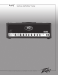
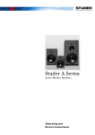
PM ONE
P r o d u c t i o n M i xe r
Operating Guide
™
Intended to alert the user to the presence of uninsulated “dangerous voltage” within the product’s
enclosure that may be of sufficient magnitude to constitute a risk of electric shock to persons.
Intended to alert the user of the presence of important operating and maintenance (servicing)
instructions in the literature accompanying the product.
CAUTION: Risk of electrical shock — DO NOT OPEN!
CAUTION: To reduce the risk of electric shock, do not remove cover. No user serviceable parts inside. Refer
servicing to qualified service personnel.
WARNING: To prevent electrical shock or fire hazard, do not expose this appliance to rain or moisture. Before
using this appliance, read the operating guide for further warnings.
Este símbolo tiene el propósito, de alertar al usuario de la presencia de “(voltaje) peligroso” sin aislamiento dentro de la caja del producto y que puede tener una magnitud suficiente como para constituir
riesgo de descarga eléctrica.
Este símbolo tiene el propósito de alertar al usario de la presencia de instruccones importantes sobre la
operación y mantenimiento en la información que viene con el producto.
PRECAUCION: Riesgo de descarga eléctrica ¡NO ABRIR!
PRECAUCION: Para disminuír el riesgo de descarga eléctrica, no abra la cubierta. No hay piezas útiles dentro.
Deje todo mantenimiento en manos del personal técnico cualificado.
ADVERTENCIA: Para evitar descargas eléctricas o peligro de incendio, no deje expuesto a la lluvia o humedad
este aparato Antes de usar este aparato, Iea más advertencias en la guía de operación.
Ce symbole est utilisé dans ce manuel pour indiquer à l’utilisateur la présence d’une tension dangereuse
pouvant être d’amplitude suffisante pour constituer un risque de choc électrique.
Ce symbole est utilisé dans ce manuel pour indiquer à l’utilisateur qu’il ou qu’elle trouvera d’importantes
instructions concernant l’utilisation et l’entretien de l’appareil dans le paragraphe signalé.
ATTENTION: Risques de choc électrique — NE PAS OUVRIR!
ATTENTION: Afin de réduire le risque de choc électrique, ne pas enlever le couvercle. Il ne se trouve à l’intérieur
aucune pièce pouvant être reparée par l’utilisateur. Confiez I’entretien et la réparation de l’appareil à un réparateur
Peavey agréé.
AVERTISSEMENT: Afin de prévenir les risques de décharge électrique ou de feu, n’exposez pas cet appareil à la
pluie ou à l’humidité. Avant d’utiliser cet appareil, lisez attentivement les avertissements supplémentaires de ce
manuel.
Dieses Symbol soll den Anwender vor unisolierten gefährlichen Spannungen innerhalb des Gehäuses
warnen, die von Ausreichender Stärke sind, um einen elektrischen Schlag verursachen zu können.
Dieses Symbol soll den Benutzer auf wichtige Instruktionen in der Bedienungsanleitung aufmerksam
machen, die Handhabung und Wartung des Produkts betreffen.
VORSICHT: Risiko — Elektrischer Schlag! Nicht öffnen!
VORSICHT: Um das Risiko eines elektrischen Schlages zu vermeiden, nicht die Abdeckung enfernen. Es befinden
sich keine Teile darin, die vom Anwender repariert werden könnten. Reparaturen nur von qualifiziertem
Fachpersonal durchführen lassen.
ACHTUNG: Um einen elektrischen Schlag oder Feuergefahr zu vermeiden, sollte dieses Gerät nicht dem Regen
oder Feuchtigkeit ausgesetzt werden. Vor Inbetriebnahme unbedingt die Bedienungsanleitung lesen.
2
PM ONEª
Professional Stereo Production Mixer
Thank you for purchasing the PM Oneª stereo production mixer. The unique features of this mixer
are sure to add to your performances, both live and recorded. The PM One is a true stereo, fully
featured mixer with the DJ in mind. With a built-in stereo graphic EQ, stereo level meter, and
assignable crossfade, the PM One adds convenience to any production system.
This manual combines both a descriptive and tutorial approach in order to explain the function(s)
of each feature. Please start at the beginning of the manual, following all safety precautions and
warnings. Failure to follow these precautions could jeapardize your safety and the safety of your
PM One.
PM One Features:
Switchable EQ
Four Stereo Input Channels
One Mic Input Channel
Two Stereo Phono Inputs
Five Stereo Line Inputs
Two Mic Inputs
Channel Input Selectors
Channel X-Fader
12 VDC Lamp Socket
Stereo LED Level Meter
Talk Switch
Cue Monitor/Assign
Stereo Headphone Output
Stereo Record Output
Stereo Amp Output
Stereo/Mono Switch
3
REAR PANEL
WARNING: TO REDUCE THE RISK OF
120V
230V
115
60Hz/230V
20 WATTS
50Hz
FIRE OR ELECTRIC SHOCK DO NOT EXPOSE
THIS EQUIPMENT TO RAIN OR MOISTURE.
TO PREVENT THE RISK OF FIRE HAZARD,
REPLACE WITH SAME TYPE 250 VOLT FUSE.
AVIS: RISQUE DE CHOC ELECTRIQUE NE PAS OUVRIR. REMPLACER PAR UNFUSIBLE DE MEME TYPE ET DE 250 VOLTS.
ONE
TM
OUTPUT
PRODUCTION
REC
MIXER
F 500 mA
250V
1
AMP
CHANNEL
THREE
LINE 5
LINE 4
CHANNEL
TWO
LINE 3
CHANNEL
ONE
LINE 2 PHONO 2
LINE 1
PHONO 1
GND
L
L
L
L
L
L
R
R
R
R
R
R
MIC 2
FUS E
FUS E
115V
CHANNEL
FOUR
4
A PRODUCT OF PEAVEY ELECTRONICS CORP.
MERIDIAN MS.
2
5
6
7
8
10
DESCRIPTIONS
POWER
The PM One is supplied with a switchable power supply. Before plugging your PM One in, please
read this entire section to ensure proper supply voltage selection and unit operation. It is important
that all safety precautions be followed.
1. VOLTAGE SELECTOR SWITCH
Use this switch to select the proper AC supply voltage for your area. This voltage varies from one
geographical area to another. For voltages between 110 and 120 VAC, select the 115 position.
For voltages between 220 and 230 VAC, select the 230 position.
2. IEC POWER CORD
This receptacle is for the IEC line cord (included), which provides AC power to the unit. Connect
the line cord to this connector and to a properly grounded AC supply. Damage to the equipment
may occur if an improper line voltage is used. (See voltage marking on unit.) Never remove or
cut the ground pin of the line cord plug. This unit is supplied with a properly rated line cord.
When lost or damaged, replace this cord with one of the proper ratings.
NOTE: FOR UK ONLY
As the colors of the wires in the mains lead of this apparatus may not correspond with the colored
markings identifying the terminals in your plug, proceed as follows: (1) The wire which is colored
green and yellow must be connected to the terminal which is marked by the letter E or by the earth
symbol or colored green or green and yellow. (2) The wire which is colored blue must be
connected to the terminal which is marked with the letter N or the color black. (3) The wire which
is colored brown must be connected to the terminal which is marked with the letter L or color red.
3. POWER ON/OFF SWITCH and LED
The Power On/Off Switch is located on the front of the PM One. (Top panel. See diagram on
page 6.) This switch in the (l) position will turn the unit on if proper voltage is supplied. The power
LED located next to the switch will illuminate when the unit is on. WARNING: PROPER
VOLTAGE MUST BE SELECTED BY THE VOLTAGE SELECTOR SWITCH (1) BEFORE THIS
SWITCH IS TURNED ON. FAILURE TO SELECT THE PROPER VOLTAGE APPLICABLE TO
YOUR POWER SOURCE COULD RESULT IN DAMAGE TO YOUR PM ONE MIXER.
4. FUSE (0.5A/250V)
The fuse is located within the cap of the fuseholder (on back panel). If the fuse should fail, IT
MUST BE REPLACED WITH THE SAME TYPE AND VALUE IN ORDER TO AVOID DAMAGE
TO THE EQUIPMENT AND TO PREVENT VOIDING THE WARRANTY. If the unit repeatedly
blows fuses, it should be taken to a qualified service center for repairs.
WARNING: THE FUSE SHOULD ONLY BE REPLACED WHEN THE POWER CORD HAS
BEEN DISCONNECTED FROM ITS POWER SOURCE.
4
OUTPUTS
The PM One features two different stereo outputs. These outputs are designed for the different
types of inputs found on various external equipment. Pay close attention to ensure you have
selected the right output for your application. Always use quality, shielded cables and verify a good
connection.
5. OUTPUT RECORD
These stereo RCA tape output jacks provide a signal for the recording inputs of a stereo tape deck.
The output signal is a -10 dBu representation of the Output Amp (6) signal.
6. OUTPUT AMP
These stereo RCA output jacks provide a line level signal for the inputs of a stereo power amplifier
and/or its associated equipment. When the Master Mono/Stereo Switch (15) is in the Mono
position, the left and right outputs become two mono outputs with an equal mix of the left and right
signals. When the Equalizer Switch (20) is on, the left and right signals will be equalized by their
respective EQÕs prior to being mixed. Therefore, the stereographic EQ comes before the switch.
This allows you to EQ the left and right channels separately, before they are mixed into a mono
signal.
INPUTS
The PM One has a variety of input combinations on various channels to give you a vast selection.
This will allow you to connect different types of products to the PM One without the extensive, costly
use of adapters. Play close attention to the descriptions and warnings in this section.
7. CHANNEL INPUTS
Channels 1 and 2 feature identical input options, PHONO and LINE. On these two channels you
may select, using the Input Select Switch (14), either PHONO (for phono players) or LINE (for line
level products such as CD, Minidisc, drum machine or DAT). This type of configuration allows you
to connect both types of products to the same channel and conveniently select between them
during a performance. Remember that this combination of inputs, PHONO and LINE, is only
available on Channels 1 and 2.
CAUTION: DO NOT CHANGE THE CHANNEL INPUT SELECT SWITCH FROM THE LINE
POSITION TO THE PHONO POSITION WHILE THE CHANNEL FADER IS TURNED UP ABOVE
Ò3Ó AND MATERIAL IS BEING PLAYED. THESE TWO TYPES OF SIGNALS DIFFER IN LEVEL.
SWAPPING BETWEEN THEM WILL NOT ALWAYS PRODUCE EQUAL OUTPUTS FROM THE
PM ONE. DOING SO COULD RESULT IN DAMAGE TO BOTH HEARING AND/OR EQUIPMENT.
Channels 3 and 4 are different, however. Channel 3 offers two stereo LINE inputs. No PHONO
inputs are available for Channel 3. You may select between the two LINE inputs using the Input
Selector Switch for Channel 3. Channel 4 has only one stereo input since its Input Selector Switch
is used to select the Mic 2 Input (10).
All output levels from your external equipment should be set to maximum levels without causing
distortion. This can sometimes be more evident by listening to the specific channel in the Cue
through headphones. One important thing to remember is that your objective is to place all
channels at very close input levels. This will make for a smoother, more accurate transition from
one device to another during crossfade and channel select operations.
NOTE: All stereo inputs are RCA connectors with the tip wired positive.
5
8. PHONO INPUT GROUND SCREW
Grounds from external turntable(s) should be connected at this point for a proper input connection.
9. MIC 1 INPUT
The Mic 1 Input is located on the top of your PM One. (See diagram on back.) The Mic 1 Input is a
balanced, low impedance controlled by the Microphone Fader (11). The Voice-over Switch (12) can
be placed in the TALK position while the Mic 1 Input is active to temporarily drop the music level by
12 dB.
10. MIC 2 INPUT
The Mic 2 Input is a balanced, low impedance TRS 1/4" input controlled by the Channel Fader (13)
of Channel 4. The Channel Input Select Switch for Channel 4 must be in the MIC 2 position for Mic
2 to be active. The Mic 2 input is located on the rear of the unit (see diagram on Page 4.)
FRONT PANEL
19
19
21
22
20
15
14
13
16
24
11
17
12
26
18
18
25
23
CHANNEL/MIC CONTROLS
This section describes the controls which affect the four individual channels and the Mic1/Mic 2
inputs. Refer to the diagram above for physical locations.
11. MICROPHONE FADER
This fader controls the level of the MIC 1 Input (9) only. The MIC 2 Input (10) is an optional
microphone input placed on Channel 4. Placing the fader in the Ò0Ó position will produce minimum
gain or no signal. Moving the fader to the Ò10Ó position will give maximum gain or the highest
output signal.
12. VOICE-OVER SWITCH
This switch is used to reduce Channels 1-4 by 12 dB. When placed in the OFF position, all
channels return to their normal level. Use this switch to punch into your program with vocal
material and punch back out to return to music.
6
13. CHANNEL FADER
This stereo fader controls the level of each individual channel regardless of input type. Placing the
fader in the Ò0Ó position will produce minimum gain or no signal. Moving the fader to the Ò10Ó
position will give maximum gain or the highest output.
14. CHANNEL INPUT SELECT SWITCH
The inputs on Channels 1 through 4 are controlled by an input selector switch. Each channel has a
designated switch that is used to select its input. The inputs of Channels 1 and 2 offer both
PHONO and LINE options. Use the switch to select which input you desire.
CAUTION: DO NOT CHANGE THE CHANNEL INPUT SELECT SWITCH FROM THE LINE
POSITION TO THE PHONO POSITION WHILE THE CHANNEL FADER IS TURNED UP AND
MATERIAL IS BEING PLAYED. THESE TWO TYPES OF SIGNALS DIFFER IN LEVEL.
SWAPPING BETWEEN THEM WILL NOT ALWAYS PRODUCE EQUAL OUTPUTS FROM THE
PM ONE. DOING SO COULD RESULT IN DAMAGE TO BOTH HEARING AND/OR EQUIPMENT.
The inputs to Channel 3 are both LINE inputs and should be somewhat similar. Bouncing back and
forth between these inputs with little change in the Channel Fader should be easy to accomplish.
The inputs to Channel 4 are very different. Use the Channel Input Select Switch to select between
LINE and MIC 2. Note: DonÕt forget that MIC 2 is live when it is selected. The Voice-over Switch
will control MIC 2. MIC 2 is an optional microphone input selectable only on Channel 4 to give you
a second microphone input if needed. Placing the Voice-over switch in the TALK position will drop
the MIC 2 level as wellas any music on the other channels. Only MIC 1 and its channel remain at
normal operating levels while TALK is selected.
MASTER CONTROLS
This section describes the master controls, which are those controls that affect the channel mix
and/or outputs. The signal produced by this section of the PM One is the signal found at the outputs.
15. MASTER MONO/STEREO SWITCH
This switch determines if the output is mono or stereo. In the MONO position, the the left and right
signals are combined and the L and R outputs are identical. You may, however, EQ them
individually with their respective equalizers prior to them becoming mono. When in the STEREO
position, the signals stay separated in true stereo. The L and R EQ/Output combination remains as
LEFT and RIGHT signals.
16. MASTER FADER
This fader controls the overall output level for outputs (5) and (6). Essentially, this is your master
volume control. Monitor the Stereo Signal Level Meter (21) to ensure your level does not exceed
the +3 dB mark and begin clipping. The optimum position for this control will produce a signal in
the 0 dB range, just slightly lighting the red LEDs at the highest peaks.
17. X-FADER
This stereo slider delivers crossfade capability between any two input channels (1-4). You will find
an X-Fader Assign selector on each side of the X-Fader. These are used to select the two input
channels that the X-Fader will crossfade between. Adjusting this slider from its maximum left
position to its maximum right position will pan the main output from being completely one channel
(the channel selected on the left X-Fader Assign) to completely another channel (the channel
7
selected on the right X-Fader Assign). The interim from left to right would produce a combination of
both, allowing a smooth transition from one channel to the other. Note: The X-Fader is replaceable
by removing the two outside mounting screws on the top of the unit. Once the screws have been
removed, the slider can be pulled out and replaced with ease.
18. X-FADER ASSIGN
The two X-Fader Assign selectors determine which two channels the X-Fader (17) controls. These
two selectors are located on each side of the X-Fader. If Channel 1 is chosen on the left selector
and Channel 4 on the right, moving the X-Fader from far left to far right will change the output mix
from Channel 1 content to Channel 4 content. The X-Fader Assign selectors allow you to change
this to match any channel combination you prefer throughout a performance.
NOTE: When Channels 3 and/or 4 are not selected on the X-Fader Assign, they respond as a
typical line mixer. This is done to allow the PM One to act as a line mixer when needed. A typical
scenario of this can be found when using a drum machine or an external effect during your
performance. By inserting the inputs from one of these devices into Channels 3 or 4, you can now
crossfade between Channels 1 and 2, while keeping a beat going with the drum machine. As you
crossfade between 1 and 2, their levels change. However, 3 and 4 continue to output at their set
level. If you want to kill 3 or 4 temporarily while crossfading between 1 and 2, simply pull the
Channel Fader down on that channel or use the Channel Input Select Switch for 3 or 4 and select
an input that does not have an active signal at the time. Either condition will make Channels 3
and/or 4 silent during a Channel 1 and 2 crossfade. When used effectively, this is a great feature to
add to your show.
19. LEFT AND RIGHT EQUALIZERS
Your PM One features two, seven-band, graphic equalizers. As labeled, one is for the Left Stereo
Channel and one is for the Right. The EQ Switch (20) must be pressed (down position) to activate
the two equalizers. The LED next to the EQ Switch will illuminate when the equalizers are active.
20. EQ SWITCH
The EQ Switch must be pressed (down position) to activate the two equalizers. The LED next to
the EQ Switch will illuminate when this condition is met and the equalizers are active. To defeat the
equalizers, return the switch to its out position and the LED will go off.
21. LEFT AND RIGHT SIGNAL LEVEL METER
This calibrated pair (L and R) of 10 segment LED meters illuminates to visually indicate program
output levels. At the top of each meter are red clip LEDs to notify you of extreme levels and
possible distortion caused by overdriving the signal.
22. 12V XLR LIGHT SOCKET
This socket accepts low voltage (12 VDC) lamps to provide sufficient light in poor lighting
situations.
8
CUE
This section identifies and describes the Cue features of the PM One. The Cue allows you to
preview and stage material prior to playing through the mains (Output-amp).
23. CUE ASSIGN
Use this selector to determine which pair of channels you would like to cue at one time. Your
options include CH 1/2, CH 3/4, and MASTER. Along with the Cue Monitor (25), you can pan
between Channels 1 and 2 or Channels 3 and 4 in your headphones. In addition, you may select
the MASTER setting to monitor the signal going to your mains.
24. CUE LEVEL
This adjusts the volume level in your headphones. It will not affect the output to your mains. Always
begin adjusting this level from the Ò0Ó position upward to avoid hearing damage.
25. CUE MONITOR
Use this fader to pan between Channels 1 and 2 or Channels 3 and 4 in your Cue mix. The
channels affected by this control are determined by the Cue Assign (23) selector.
26. HEADPHONE OUTPUT
This stereo 1/4" jack provides a Cue output for a standard pair of stereo headphones. Use the Cue
Level (24) to adjust the volume. Use the Cue Assign (23) and the Cue Monitor (25) to determine
what you wish to monitor.
9
PMª One Recommended Hookup for DJÕs
Mini Disc
Drum Machine
Turntable
CD Player
CD Player
Wireless Mic*
Hi Z Mic
Turntable
CH. A Input
L/R Input
CH. B Input
SP¨2GÕs
Tape Deck
CH. A Output
CS¨800s
CH. B Output
PVM¨ 22
Headphones
*NOTE: Wireless mics are typically mono. From the line out (mono) of the wireless
mic receiver, it will be necessary to use a stereo splitter in order to utilize
both the left and right channels of an input channel.
10
PMª One Recommended Hookup for Production
CD Player
Wireless Mic*
Tape Deck
Wireless Mic*
L/R Input
CH. A Input
L/R Input
CH. B Input
SP¨2GÕs
Tape Deck
CH. A Output
CS¨800s
CH. B Output
PVM¨ 22
Headphones
*NOTE: Wireless mics are typically mono. From the line out (mono) of the wireless
mic receiver, it will be necessary to use a stereo splitter in order to utilize
both the left and right channels of an input channel.
11
PM ONE
SPECIFICATIONS
Inputs:
Microphone:
1m V 47 k Ohm/High impedance
Phone:
3m V 47 k Ohm
Line/Tape/CD:
150m V 27 k Ohm
Output:
1.5 Volt max
Frequency response:
20-20,000 Hz ± 3 dB
Distortion:
±0.08%
S/N ratio:
More than 60 dB
Attenuation at Voice over:
-12 dB
Equalization range:
+/-12 dB with independent channels on the bands 60 Hz,
150 Hz, 400 Hz, 1 kHz, 2 kHz, 4 kHz, 6 kHz, 15 kHz.
Headphone monitor impedance:
16 Ohm/Output 250mV
Power source:
AC 110/220 V, 50/60Hz, 15 Watt
Dimensions:
19" (W) X 9.5" (D) X 4.25" (H)
482 (W) mm X 240 (D) mm X 110 (H) mm
Weight:
8.4 lbs. (3.8 kg)
12
NOTES:
13
IMPORTANT SAFETY INSTRUCTIONS
WARNING: When using electric products, basic cautions should always be followed, including the following:
1.
Read these instructions.
2.
Keep these instructions.
3.
Heed all warnings.
4.
Follow all instructions.
5.
Do not use this apparatus near water. For example, near or in a bathtub, swimming pool, sink, wet basement, etc.
6.
Clean only with a damp cloth.
7.
Do not block any of the ventilation openings. Install in accordance with manufacturerÕs instructions. It should not be placed flat
against a wall or placed in a built-in enclosure that will impede the flow of cooling air.
8.
Do not install near any heat sources such as radiators, heat registers, stoves or other apparatus (including amplifiers) that
produce heat.
9.
Do not defeat the safety purpose of the polarized or grounding-type plug. A polarized plug has two blades with one wider than the
other. A grounding type plug has two blades and a third grounding plug. The wide blade or third prong is provided for your safety.
When the provided plug does not fit into your inlet, consult an electrician for replacement of the obsolete outlet. Never break off
the grounding. Write for our free booklet ÒShock Hazard and GroundingÓ. Connect only to a power supply of the type marked on
the unit adjacent to the power supply cord.
10. Protect the power cord from being walked on or pinched, particularly at plugs, convenience receptacles, and the point they exit
from the apparatus.
11. Only use attachments/accessories provided by the manufacturer.
12. Use only with a cart, stand, tripod, bracket, or table specified by the manufacturer, or sold with the apparatus. When a cart is
used, use caution when moving the cart/apparatus combination to avoid injury from tip-over.
13. Unplug this apparatus during lightning storms or when unused for long periods of time.
14. Refer all servicing to qualified service personnel. Servicing is required when the apparatus has been damaged in any way, such
as power-supply cord or plug is damaged, liquid has been spilled or objects have fallen into the apparatus, the apparatus has
been exposed to rain or moisture, does not operate normally, or has been dropped.
15. If this product is to be mounted in an equipment rack, rear support should be provided.
16. Exposure to extremely high noise levels may cause a permanent hearing loss. Individuals vary considerably in susceptibility to
noise-induced hearing loss, but nearly everyone will lose some hearing if exposed to sufficiently intense noise for a sufficient
time. The U.S. GovernmentÕs Occupational and Health Administration (OSHA) has specified the following permissible noise level
exposures:
Duration Per Day In Hours
8
6
4
3
2
1 1/2
1
1/2
1/4 or less
Sound Level dBA, Slow Response
90
92
95
97
100
102
105
110
115
According to OSHA, any exposure in excess of the above permissible limits could result in some hearing loss. Ear plugs or protectors
to the ear canals or over the ears must be worn when operating this amplification system in order to prevent a permanent hearing
loss, if exposure is in excess of the limits as set forth above. To ensure against potentially dangerous exposure to high sound
pressure levels, it is recommended that all persons exposed to equipment capable of producing high sound pressure levels such as
this amplification system be protected by hearing protectors while this unit is in operation.
SAVE THESE INSTRUCTIONS!
14
PEAVEY ELECTRONICS CORPORATION LIMITED WARRANTY
Effective Date: July 1, 1998
What This Warranty Covers
Your Peavey Warranty covers defects in material and workmanship in Peavey products purchased and serviced in the U.S.A. and Canada.
What This Warranty Does Not Cover
The Warranty does not cover: (1) damage caused by accident, misuse, abuse, improper installation or operation, rental, product modification or
neglect; (2) damage occurring during shipment; (3) damage caused by repair or service performed by persons not authorized by Peavey; (4) products
on which the serial number has been altered, defaced or removed; (5) products not purchased from an Authorized Peavey Dealer.
Who This Warranty Protects
This Warranty protects only the original retail purchaser of the product.
How Long This Warranty Lasts
The Warranty begins on the date of purchase by the original retail purchaser. The duration of the Warranty is as follows:
Product Category
Duration
Guitars/Basses, Amplifiers, Pre-Amplifiers, Mixers, Electronic
Crossovers and Equalizers
2 years *(+ 3 years)
Drums
2 years *(+ 1 year)
Enclosures
3 years *(+ 2 years)
Digital Effect Devices and Keyboard and MIDI Controllers
1 year *(+ 1 year)
Microphones
2 years
Speaker Components (incl. speakers, baskets, drivers,
diaphragm replacement kits and passive crossovers)
and all Accessories
1 year
Tubes and Meters
90 days
[*denotes additional warranty period applicable if optional Warranty Registration Card is completed and returned to Peavey by original retail purchaser within 90
days of purchase.]
What Peavey Will Do
We will repair or replace (at Peavey's discretion) products covered by warranty at no charge for labor or materials. If the product or component must
be shipped to Peavey for warranty service, the consumer must pay initial shipping charges. If the repairs are covered by warranty, Peavey will pay the
return shipping charges.
How To Get Warranty Service
(1) Take the defective item and your sales receipt or other proof of date of purchase to your Authorized Peavey Dealer or Authorized Peavey
Service Center.
OR
(2) Ship the defective item, prepaid, to Peavey Electronics Corporation, International Service Center, 412 Highway 11 & 80 East, Meridian, MS 39301
or Peavey Canada Ltd., 95 Shields Court, Markham, Ontario, Canada L3R 9T5. Include a detailed description of the problem, together with a copy of
your sales receipt or other proof of date of purchase as evidence of warranty coverage. Also provide a complete return address.
Limitation of Implied Warranties
ANY IMPLIED WARRANTIES, INCLUDING WARRANTIES OF MERCHANTABILITY AND FITNESS FOR A PARTICULAR PURPOSE, ARE LIMITED
IN DURATION TO THE LENGTH OF THIS WARRANTY.
Some states do not allow limitations on how long an implied warranty lasts, so the above limitation may not apply to you.
Exclusions of Damages
PEAVEY'S LIABILITY FOR ANY DEFECTIVE PRODUCT IS LIMITED TO THE REPAIR OR REPLACEMENT OF THE PRODUCT, AT PEAVEY'S
OPTION. IF WE ELECT TO REPLACE THE PRODUCT, THE REPLACEMENT MAY BE A RECONDITIONED UNIT. PEAVEY SHALL NOT BE
LIABLE FOR DAMAGES BASED ON INCONVENIENCE, LOSS OF USE, LOST PROFITS, LOST SAVINGS, DAMAGE TO ANY OTHER EQUIPMENT
OR OTHER ITEMS AT THE SITE OF USE, OR ANY OTHER DAMAGES WHETHER INCIDENTAL, CONSEQUENTIAL OR OTHERWISE, EVEN IF
PEAVEY HAS BEEN ADVISED OF THE POSSIBILITY OF SUCH DAMAGES
Some states do not allow the exclusion or limitation of incidental or consequential damages, so the above limitation or exclusion may not
apply to you.
This Warranty gives you specific legal rights, and you may also have other rights which vary from state to state.
If you have any questions about this warranty or service received or if you need assistance in locating an Authorized Service Center, please contact
the Peavey International Service Center at (601) 483-5365 / Peavey Canada Ltd. at (905) 475-2578.
Features and specifications subject to change without notice.
15
Peavey Electronics Corporation ¥ 711 A Street ¥ Meridian, MS 39301
(601) 483-5365 ¥ Fax (601) 486-1278 ¥ www.peavey.com
©1999