1
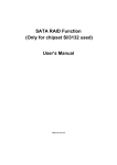
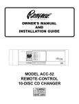
VOLUME
MO
AV303
STEREO
CASSETTE
AV-303
DX
ST
LO
TUNING
FF/EJ
POWER
BAND
BALANCE
AM/FM RADIO
WITH
DETACHABLE FRONT PANEL
AND
CASSETTE PLAYER
OWNER'S MANUAL
Released 9-25-02
INSTALLATION INSTRUCTIONS
This unit is designed for installation in cars, trucks, and vans with an existing radio opening. In many cases, a special installation kit will be
required to mount the radio to the dashboard. These kits are available at electronics supply stores and car stereo specialist shops. Always
check the kit application before purchasing to make sure the kit works with your vehicle. If you need a kit but cannot find it available, call
our toll-free “HELP” line. Just call our toll-free telephone assistance line at 1-800-645-4994 (U.S.A. and Canada only).
UNIVERSAL INSTALLATION
1. Remove the detachable front panel if it is attached to the chassis by pushing the “Release” button. Slide the mounting sleeve
off of the chassis. If it is locked into position, use the removal tools (supplied) to disengage it.
2. Check the dashboard opening size by sliding the mounting sleeve into it. If the opening is not large enough, carefully cut or
file as necessary until the sleeve easily slides into the opening. Do not force the sleeve into the opening or cause it to bend
or bow. Check that there will be sufficient space behind the dashboard for the radio chassis.
3. Locate the series of bend tabs along the top, bottom, and sides of the mounting sleeve. With the sleeve fully inserted into the
dashboard opening, bend as many of the tabs outward as necessary so that the sleeve is firmly secured to the dashboard.
4. Place the radio in front of the dashboard opening so that the wiring can be brought through the mounting sleeve. Follow the
wiring diagram carefully and make certain all connections of the wiring harness are secure and insulated with wire nuts or
electrical tape to insure proper operation of the unit. After completing the wiring connections, attach the front panel and turn
the unit on to confirm operation (ignition switch must be “on”). If unit does not operate, re-check all wiring until problem is
corrected. Once proper operation is achieved, turn off the ignition switch and proceed with final mounting of the chassis.
5. Carefully slide the radio into the mounting sleeve making sure it is right-side-up until it is fully seated and the spring clips lock
it into place.
6. Attach one end of the perforated support strap (supplied) to the screw stud on the rear of the chassis using the hex nut provided.
Fasten the other end of the perforated strap to a secure part of the dashboard either above or below the radio using the screw
and hex nut provided. Bend the strap to position it as necessary.
CAUTION: The rear of the radio must be supported with the strap to prevent damage to the dashboard from the weight of the
radio or improper operation due to vibration.
7. Re-attach the front panel to the chassis and test radio operation by referring to the Operating Instructions for the unit.
INSTALLATION USING KITS
1. If your vehicle requires the use of an installation kit to mount this radio, follow the instructions included with the installation kit
to attach the radio to the mounting plate supplied with the kit.
2. Wire and test the radio as described in Step 4 above.
3. Install the radio/mounting plate assembly to the sub-dashboard according to the instructions of the installation kit.
4. Attach the support strap to the radio and dashboard as described in Step 6 above.
5. Replace the dashboard trim panel.
-2-
EXISTING DASH OPENING (FILE EDGES TO FIT IF NECESSARY-DO NOT OVER FILE)
NOTE: IF DASH IS SOLID, USE MOUNTING SLEEVE AS A TEMPLATE & CUT OPENING
NUT
PERFORATED STRAP
FASTEN THIS END TO
SCREW STUD ON
REAR OF CHASSIS
UNIVERSAL INSTALLATION
BEND TOP TABS
UPWARD
BEND BOTTOM TABS
DOWNWARD
SCREW
RADIO
SCREW STUD
NUT
REMOVAL
TOOL (1)
MOUNTING SLEEVE
FASTEN THIS END TO SECURE PART
OF DASHBOARD.
DRILL HOLE IF NECESSARY.
DETACHABLE FRONT PANEL
-3-
ANTENNA
WIRING DI
AGR
AM
DIA
GRA
RADIO
12
1212
12
12
12
12
12
USE 1/4"
11
12345678
12
12
EXISTING
ANTENNA
CABLE
1
123456789
12
SPADE LUG
1
1
AUTO ANTENNA
FOR GROUND
11
ORANGE
111
(+12 VDC OUTPUT WHEN
CONNECTION
1
GROUNDED METAL PART
111
RADIO IS ON)
OF CAR BODY
1111
1
(REMOVE ANY PAINT)
111
IMPORTANT
BLACK
CONNECT THE RED WIRE TO A
1111
SWITCHED +12 VOLT SOURCE.
1111
RED
1
111
FUSE (3 AMP.)
1111
RIGHT SPEAKER
LEFT SPEAKER
1111
1
111
1111
GREEN
GRAY
11
1
GREEN
W/WHITE STRIPE11
GRAY w/WHITE STRIPE 12
1
1234567890123456
12345678901234567890
11
12
12
ANTENNA SOCKET
ON REAR OF RADIO
4 - 8 OHMS
USE WIRE NUTS OR SOLDER AND TAPE ALL SPLICES
-4-
4 - 8 OHMS
4 SPE
A K ER SY
STEM WIRING
SPEA
SYSTEM
TO RADIO
12
12
12
12
12
12
12
12
12
12
12
12
12
12
12
12
12
12
12
12
12
12
12
1212
GRAY w/WHITE STRIPE
WHITE
GREEN
12
12
12
12
12
12
12
12
12
12
12
12
12
12
12
12
12
12
12
12
12
12
1212
12
GREEN W/WHITE STRIPE
LEFT FRONT SPEAKER
RIGHT FRONT SPEAKER
GRAY
USE WIRE NUTS OR SOLDER
AND TAPE ALL SPLICES
RIGHT REAR SPEAKER
LEFT REAR SPEAKER
NOTE: CONNECT ALL OTHER WIRES AS SHOWN ON PAGE 4
-5-
OPERATING INSTRUCTIONS
1
12
11
2
VOLUME
VOLUME
MO
DX
ST
14
AV303
STEREO
CASSETTE
LO
6
FF/EJ
POWER
BAND
TUNING
4
BALANCE
10
8
5
9
7, 13
1 POWER ON-OFF BUTTON
Alternately press this button to turn the unit on and
off.
2
VOLUME CONTROL
To increase the volume level, rotate this control knob
in the clockwise (CW) direction; to decrease the
volume, rotate the knob in the counterclockwise
(CCW) direction.
-6-
3
3 BALANCE CONTROL
Rotate this control knob to achieve sound output
balance between the left and right speakers. Output
balance will occur when the control is positioned at
the center detent position.
To favor the sound output from the left speaker(s),
rotate the control CCW; to favor the sound output
from the right speaker(s), rotate the control CW.
4 TONE CONTROL
8 FM MONO/STEREO (MO.ST) BUTTON
Rotate this control knob to adjust the sound output
for the desired bass or treble tonal range. When the
control is positioned at the mid-range detent position, the bass and treble response should be very
nearly equal.
To increase bass response, rotate the control CCW;
to increase treble response, rotate the control CW.
During FM radio reception, this button is used to
select mono or stereo reception. Under normal
reception conditions, the unit should be left in the
stereo mode, as indicated by the FM Stereo
indicator. If the stereo signal is too noisy for comfortable listening, press the MO.ST button to switch to
mono reception.
5 AM-FM BAND SELECTOR
Press this button to change the radio band from AM
to FM and vice-versa.
6 MANUAL TUNING CONTROL
Rotate this knob to the left or right to select the
desired radio station. When tuning in a station,
always adjust the control so that you are receiving
the full signal and are on the center of the broadcast
frequency. If the radio is off frequency, you could
experience noise and reception problems. The pointer
will move along the dial to indicate the frequency to
which you are tuned.
7 FM STEREO INDICATOR
This LED indicator within the AM/FM dial will illuminate red during reception of FM stereo broadcasts;
if the stereo station is mistuned (not in the center of
the frequency) this indicator may light intermittently
or not at all.
-7-
9 LOCAL/DISTANT (LO.DX) BUTTON
This button allows maximum reception in both weak
and strong FM signal areas. For normal reception
conditions, and when receiving a wide range of
signals, including weak or distant stations, this
function should be set to the Distant (DX) position,
which will allow maximum signal reception. When in
an extremely strong (local) signal area, select the
Local (LO) setting. This will eliminate weak signals
and suppress overly strong signals. When moving
out of the strong signal area, switch to the Distant
setting.
NOTE: The Local/Distant button only affects FM
signals, and will have no effect on AM
signals.
bl AM ANTENNA TRIMMER
It is very important to adjust the Antenna Trimmer for
optimum AM reception. The antenna trimmer is
located on left rear corner of the chassis. Adjust this
control after wiring connections are complete and
before the radio is inserted into the dashboard
opening. Proceed as follows:
1.Tune in a weak station around 1400 kHz on the
AM band.
2.Using a small screwdriver, slowly adjust the
trimmer for maximum output from the radio.
NOTE:
The Antenna Trimmer only affects AM
reception, and will have no effect on FM
reception. The Trimmer only needs to be
adjusted when the radio is first installed
and at any time a change is made to the
vehicle antenna (replacing the mast, etc.).
bm CASSETTE DOOR
This button performs two functions. To eject a
cassette, simply press the button fully then release.
The cassette will eject and radio operation will
resume.
To fast-forward the tape, press the button half-way in
to the locked position. To stop fast-forward and
resume normal tape playback, press the button
slightly and release. Do not press fully in or the
cassette will be ejected.
NOTE: Never leave a cassette engaged in the
player when not in use. Doing so can
cause damage to the cassette and/or
mechanism of the unit. Always press the
eject button and remove the cassette
when leaving the vehicle.
bo AM/FM DIAL DISPLAY
Hold the cassette with the exposed tape edge to the
right and insert it into the cassette door. Press in
fully until the cassette is engaged and begins
playing.
NOTE:
bn FAST-FORWARD/EJECT (FF/EJ) BUTTON
This dual tuning dial represents the AM (bottom)
frequency band from 530-1710 kHz, while the top
dial represents the FM frequency band from
87.7-107.9 MHz. The AM station frequencies on
the dial must be multiplied by a factor of 10 (x10)
as shown. The dial pointer traverses the dial using
the TUNING control knob in conjunction with the
AM/FM BAND select button.
Observe the cassette operation cautions
in the Care and Maintenance section of
this manual.
-8-
bp FRONT PANEL RELEASE (REL) BUTTON
DETACHING THE FRONT PANEL
This button is used to release the mechanism that
holds the front panel to the chassis. To detach the
front panel, press the button so that the right side of
the panel is released. Grasp the released side and
pull it off of the chassis. To re-attach the panel,
position the right side of the panel in place first and
then press the left side of the panel until the mechanism locks it into place.
NOTES ON USE OF FRONT PANEL
1. Make sure the front panel is right-side-up when
attaching it to the chassis as it cannot be
attached when upside down.
2. Do not press very hard on the front panel when
attaching it to the chassis. No more than light to
moderate pressure should be needed.
3. When attaching the front panel, make sure the
right side is correctly engaged before pressing
the left side to lock it into position.
-9-
Release Button
1
2
ATTACHING THE FRONT PANEL
Engage right
side first
CARE AND MAINTENANCE
The radio portion of your new sound system does not require any maintenance. We recommend you keep this manual for
general reference of the many features found in this unit.
As with any cassette player, the cassette section of this sound system does require a minimum of maintenance to keep it
in good working condition. The following simple care and maintenance suggestions should be followed to prevent
malfunctions of the cassette system.
Cassette Care:
1. Purchase a cassette cleaning kit from your local retail store. Use it! At least every 20 to 30 hours of operation
you must clean the cassette mechanism. A dirty cassette player will have a poor sound.
2. Do not use cassettes that exceed 45 minutes of play on each side.
3. Do not insert a cassette that appears to be broken, twisted or dirty or with loose or torn labels on it.
4. Always keep your cassettes away from direct sunlight or exposure to sub-freezing conditions. If a cassette
is cold, allow it to warm up before use.
5. Do not keep a cassette in the player when not in use.
6. Before inserting a cassette in the player, check that the tape is tightly wound on the reels.
Take up any excess slack using a pencil to turn the drive hub in the cassette (see diagram).
SPECIFICATIONS
Size:
Operating Voltage:
Output Power
Output Wiring:
7.2" W x 2" H x 5.1" D (182mm x 52mm x 130mm)
12 volts DC, negative ground (Fuse: 3 Amp.)
14 watts maximum (7 watts x 2 channels)
Common-ground type designed for 2 speaker use.
May also be used with 4 speakers.
Output Impedance:
Compatible with 4-8 ohm speakers
Tuning Range:
AM: 530 - 1710 kHz., FM: 87.7 - 107.9 MHz.
Sensitivity:
AM: 100 uV; FM: 10 uV (for 30dB quieting).
FM Stereo Separation:
30 dB
Tape Frequency Response: 50-10,000 Hz.
Tape S/N Ratio:
50 dB
Wow & Flutter:
0.25% WRMS
* Specifications are subject to change without notice.
Modifications not authorized by the manufacturer may void users authority to operate this device.
-10-
12 MONTH LIMITED WARRANTY
AUDIOVOX CORPORATION (the Company) warrants to the original retail purchaser of this product that should
this product or any part thereof, under normal use and conditions, be proven defective in material or workmanship
within 12 months from the date of original purchase, such defect(s) will be repaired or replaced with new or
reconditioned product (at the Company's option) without charge for parts and repair labor.
To obtain repair or replacement within the terms of this Warranty, the product is to be delivered with proof of
warranty coverage (e.g. dated bill of sale), specification of defect(s), transportation prepaid, to the warranty center
at the address shown below.
This Warranty does not extend to the elimination of car static or motor noise, to correction of antenna problems,
to costs incurred for installation, removal, or reinstallation of the product, or damage to tapes, compact discs,
speakers, accessories, or vehicle electrical systems.
This Warranty does not apply to any product or part thereof which, in the opinion of the Company, has suffered
or been damaged through alteration, improper installation, mishandling, misuse, neglect, accident, or by removal
or defacement of the factory serial number/bar code label(s). THE EXTENT OF THE COMPANY'S LIABILITY
UNDER THIS WARRANTY IS LIMITED TO THE REPAIR OR REPLACEMENT PROVIDED ABOVE AND, IN NO
EVENT, SHALL THE COMPANY'S LIABILITY EXCEED THE PURCHASE PRICE PAID BY PURCHASER FOR
THE PRODUCT.
This Warranty is in lieu of all other express warranties or liabilities. ANY IMPLIED WARRANTIES, INCLUDING
ANY IMPLIED WARRANTY OF MERCHANTABILITY, SHALL BE LIMITED TO THE DURATION OF THIS
WRITTEN WARRANTY. ANY ACTION FOR BREACH OF ANY WARRANTY HEREUNDER INCLUDING ANY
IMPLIED WARRANTY OF MERCHANTABILITY MUST BE BROUGHT WITHIN A PERIOD OF 30 MONTHS
FROM DATE OF ORIGINAL PURCHASE. IN NO CASE SHALL THE COMPANY BE LIABLE FOR ANY
CONSEQUENTIAL OR INCIDENTAL DAMAGES FOR BREACH OF THIS OR ANY OTHER WARRANTY,
EXPRESS OR IMPLIED, WHATSOEVER. No person or representative is authorized to assume for the Company
any liability other than expressed herein in connection with the sale of this product.
Some states do not allow limitations on how long an implied warranty lasts or the exclusion or limitation of incidental
or consequential damage so the above limitations or exclusions may not apply to you. This Warranty gives you
specific legal rights and you may also have other rights which vary from state to state.
U.S.A. : AUDIOVOX CORPORATION, 150 MARCUS BLVD., HAUPPAUGE, NEW YORK 11788 " 1-800-645-4994
CANADA: CALL 1-800-645-4994 FOR LOCATION OF WARRANTY STATION SERVING YOUR AREA
128-4270E
-11-
© 2002 Audiovox Corp., 150 Marcus Blvd., Hauppauge, N.Y. 11788
Printed in China
128-6474
-12-