1
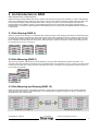
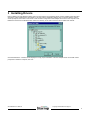
SATARAID5™ Serial ATA RAID5 Management Software Home Edition Users Manual 07/01/04 Silicon Image, Inc. 1060 East Arques Ave. Sunnyvale CA 94085 (408) 616-4000 www.siliconimage.com Copyright © 2004, Silicon Image, Inc. All rights reserved. No part of this publication may be reproduced, transmitted, transcribed, or translated into any language or computer format, in any form or by any means without prior written permission of: Silicon Image, Inc. 1060 East Arques Ave. Sunnyvale CA 94085 Silicon Image, Inc. reserves the right to make changes to the product(s) or specifications to improve performance, reliability, or manufacturability. Information furnished is believed to be accurate and reliable, but Silicon Image, Inc. shall not be responsible for any errors that may appear in this document. Silicon Image, Inc. makes no commitment to update or keep current the information contained in this document. However, no responsibility is assumed for its use; nor any infringement of patents or other rights of third parties, which may result from its use. No liability is assumed as a result of their use or application. No rights under any patent accompany the sale of any such product(s) or information. Silicon Image, Inc. products are not designed or intended for use in Life Support Systems. A Life Support System is a product or system intended to support or sustain life, which if it fails, can be reasonably expected to result in significant personal injury or death. If Buyer or any of its direct or indirect customers applies any product purchased or licensed from Silicon Image, Inc. to any such unauthorized use, Buyer shall indemnify and hold Silicon Image, Inc., its affiliates and their respective suppliers, harmless against all claims, costs, damages and expenses arising directly or indirectly, out of any such unintended or unauthorized use, even if such claims alleges that Silicon Image, Inc. or any other person or entity was negligent in designing or manufacturing the product. Specifications are subject to change without notice. SATARAID5 is a trademark of Silicon Image, Inc. JAVA is a trademark of Sun Microsystems, Inc. Windows is a trademark of Microsoft Corp. for their family of computer operating systems. Revision History: Revision Comment 1.00 Initial creation of document 04/06/04 1.01 Updated for beta release. 04/30/04 1.02 Included “For SATARaid users” section. 05/07/04 1.03 Update chapter 6 based on BIOS changes. 06/17/04 1.04 Minor edits and clarifications 06/26/04 1.05 Update for new features for configuring SATARAID5. 06/30/04 1.06 Replaced some screen pictures with new ones to show the new product name. 07/01/04 Copyright © 2004 Silicon Image Inc. 2 Date SATARAID5 User’s Manual 1 WELCOME 5 1.1 SATARAID5 FEATURES 1.2 FOR SATARAID USERS UPGRADING TO SATARAID5 1.2.1 RAID FUNCTION LIST FOR DIFFERENT VERSIONS OF BIOS AND RAID DRIVER 1.2.2 UPGRADE BIOS AND RAID DRIVER 5 5 5 6 2 7 AN INTRODUCTION TO RAID 2.1 DISK STRIPING (RAID 0) 2.2 DISK MIRRORING (RAID 1) 2.3 DISK MIRRORING AND STRIPING (RAID 10) 2.4 PARITY RAID (RAID 5) 2.5 JBOD (JUST BUNCH OF DISKS) 7 7 7 8 8 3 INSTALLING DRIVERS 9 4 JAVA 2 RUNTIME ENVIRONMENT INSTALLATION 10 5 SATARAID5 GUI INSTALLATION 12 6 CREATING AND DELETING LEGACY RAID GROUPS WITH BIOS UTILITY 13 6.1 6.2 6.3 6.4 6.5 6.6 6.7 6.8 6.9 7 CREATING RAID GROUPS CREATING SPARE DRIVE CREATING JBOD DELETING RAID GROUPS, SPARE DRIVE, AND JBOD REBUILD RAID 1 SET RESOLVING CONFLICTS LOW LEVEL FORMATTING LOGICAL DRIVE INFORMATION RESERVED DRIVE AND SETTING SIZE FOR RAID SET, SPARE DRIVE, OR JBOD ALLOCATING PARTITIONS IN WINDOWS 15 16 16 17 18 19 21 21 21 23 7.1 WINDOWS SERVER 2003 & XP & 2000 7.1.1 CREATING THE PARTITIONS 23 24 8 28 SATARAID5 GUI OVERVIEW SATARaid5 User’s Manual Copyright © 2004 Silicon Image Inc. 3 8.1 RAID GROUPS AND DEVICE CONFIGURATION WINDOWS 8.2 SATARAID5 MENU COMMANDS 8.2.1 CONFIGURATION 8.2.2 EXIT 8.2.3 CREATE SPARE 8.2.4 DELETE SPARE 8.2.5 DELETE MEMBER 8.2.6 DELETE ORPHAN 8.2.7 DEVICE SUMMARY 8.2.8 CREATE RAID GROUP 8.2.9 REBUILD RAID GROUP 8.2.10 DELETE RAID GROUP 8.2.11 RAID GROUP SUMMARY 8.2.12 TASK MANAGER 8.2.13 EVENT LOG 8.2.14 RESOURCES 8.2.15 CREATE LEGACY RAID GROUP 8.2.16 REBUILD LEGACY RAID GROUP 8.2.17 DELETE LEGACY RAID GROUP 8.2.18 CONVERT LEGACY RAID GROUP 8.2.19 CREATE LEGACY SPARE 8.2.20 DELETE LEGACY SPARE 8.2.21 CONVERT LEGACY SPARE 8.2.22 HELP TOPICS 8.2.23 ABOUT Copyright © 2004 Silicon Image Inc. 4 28 30 31 35 36 36 37 37 38 39 41 41 42 44 48 50 50 51 51 52 52 53 53 54 54 SATARAID5 User’s Manual 1 Welcome TM Silicon Image’s SATARAID5 software provides Serial ATA RAID 0 (Striping), RAID 1 (Mirroring), RAID 5 (Parity RAID), RAID 10 (Striping and Mirroring), and JBOD (just a bunch of disks) functionality to enhance the industry’s leading PCI-to-SATA host controller products. Two major challenges facing the storage industry today are keeping pace with the increasing performance demands of computer systems by improving disk I/O throughput and providing data accessibility in the face of hard disk failures while utilizing full disk capacity. With SiIicon Image Serial ATA host controller and SATARAID5, both of these problems are solved. SATARAID5 software provides a Graphical User Interface (GUI) for easy-to-use configurations of the RAID Groups. 1.1 SATARAID5 Features • • • • • • • • • • • • • • RAID 0, RAID 1, RAID 5, RAID 10, and JBOD Groups are supported. Supported OS: Win2000/XP/Server 2003. RAID Groups can be created and deleted without exiting Windows. Hot Spare and On-line Rebuilding. The spare policy supports testing periodically for a health check of the spare disk. Spare drive can be global or dedicated to a specific RAID group. Supports Auto and Manual rebuild policy for a RAID group. System GUI Monitoring Utility: • Displays/Logs/Alerts Users to Vital RAID Group Information. • Manages RAID Group Functions (configures, rebuilds, etc.,). Supports the ability to partition and map a segment of disk to a virtual LUN or disk. Supports up to two RAID groups. Any excess capacity on disk drives can be formatted as independent logical drives. Adjustable Stripe Size for RAID 0, RAID 5, and RAID 10. Uses the Self-Monitoring, Analysis, and Reporting Technology (SMART) feature in the attached drives for automatic notification of imminent drive failures. Employ RAID recovery algorithms to maintain data integrity in the event of a disk failure including bad block management. Automatically Selects Highest Available Transfer Speed for All SATA Devices. Supports the following: • Data transfer rate up to 150MB/Sec (SiI3114, SiI3124-1), and 300MB/Sec (SiI3124-2) • Support up to 4 SATA devices connected to a single controller. • ACPI, SATA 1.0 (SiI3114, Sii3124-1), and SATA 2.0 (SiI3124-2) Supports drive roaming capability allowing drives from one controller to be moved to another without loss of data. Employs a task manager for the scheduling of any RAID or disk management operations including RAID group creation, rebuild, and test. 1.2 For SATARaid Users upgrading to SATARaid5 If you plan to upgrade to RAID 5 driver and/or BIOS from previous drivers without RAID 5 capability, read this section carefully before upgrading BIOS and/or RAID driver. Otherwise, you might get unexpected results. We do not recommend downgrading from RAID 5 driver to the previous (non-RAID 5) RAID driver. 1.2.1 RAID Function List for Different Versions of BIOS and RAID Driver The following list shows possible BIOS and RAID driver combination and RAID functions supported by each combination. (Legacy RAID group is a RAID set that is compatible with older SiI3112A, SiI3114, and SiI3124 SATARaid software drivers). 1. 2. Old BIOS with Old RAID Driver • Non-RAID Hard Disk • Legacy RAID 0 group • Legacy RAID 1 group • Legacy RAID 10 group • Legacy spare drive Old BIOS with New RAID Driver • Legacy RAID 0 group • Legacy RAID 1 group • Legacy RAID 10 group • Legacy spare drive SATARaid5 User’s Manual Copyright © 2004 Silicon Image Inc. 5 3. 4. • New RAID 0 group (BIOS will not recognize this) • New RAID 1 group (BIOS will not recognize this) • New RAID 5 group (BIOS will not recognize this) • New RAID 10 group (BIOS will not recognize this) • New spare drive (BIOS will not recognize this) • JBOD (BIOS will not recognize this) RAID 5 BIOS with Old RAID Driver • Legacy RAID 0 group • Legacy RAID 1 group • Legacy RAID 10 group • Legacy spare drive RAID 5 BIOS with New RAID Driver • Legacy RAID 0 group • Legacy RAID 1 group • Legacy RAID 10 group • Legacy spare drive • New RAID 0 group • New RAID 1 group • New RAID 5 group • New RAID 10 group • New spare drive • JBOD 1.2.2 Upgrade BIOS and RAID Driver If you upgrade from old BIOS and old RAID driver to a newer version of BIOS and/or RAID drive, you may lose some functions. Also, the new driver may not recognize non-RAID drives. If you are upgrading the software driver from the previous nonRAID 5 versions, the following is a list of precautions users should realize before upgrading BIOS and RAID driver to a newer version. 1. 2. 3. If you’re upgrading to RAID 5 driver only: • If the boot drive is a non-RAID drive, the system will not boot. • No non-RAID drive support. • When creating RAID groups through GUI, only those RAID groups created in legacy mode will be recognized by BIOS. • The existing RAID 0 or RAID 10 groups (created with previous version of BIOS or GUI) with 4 KB stripe size will not work. If you’re upgrading to RAID 5 BIOS only: • If the boot drive is a non-RAID drive, the system will not boot. • No non-RAID drive support. • RAID driver will not recognize JBOD and RAID 5 group created by BIOS. If you’re upgrading to RAID 5 BIOS and RAID 5 driver • If the boot drive is a non-RAID drive, the system will not boot. • No non-RAID drive support. • The existing RAID 0 or RAID 10 groups (created with previous version of BIOS or GUI) with 4 KB strip size will not work. Copyright © 2004 Silicon Image Inc. 6 SATARAID5 User’s Manual 2 An Introduction to RAID RAID - Redundant Array of Independent Disks RAID technology manages multiple disk drives to enhance I/O performance and provide redundancy in order to withstand the failure of any individual member, without the loss of data. There are many different methods of implementation for RAID, with each having advantages and disadvantages. Raid levels or set types are given a numerical designator that defines its implementation such as RAID 0 or RAID 1. SATARAID5 provides support for three RAID Group types: Striped (RAID 0), Mirrored (RAID 1), and RAID 10 Mirrored/Striped. Other RAID types are not supported by SATARAID5 software and thus are not discussed. 2.1 Disk Striping (RAID 0) Striping is a performance-oriented, non-redundant data mapping technique. While Striping is discussed as a RAID Group type, it is does not provide any fault tolerance. With modern SATA and ATA bus mastering technology, multiple I/O operations can be performed in parallel, enhancing data throughput. Striping arrays use multiple disks to form a larger virtual disk. The figure below illustrates a three-disk stripe set. Stripe one is written to disk one, stripe two to disk two, and so forth. RAID 0 sets can be comprised of two, three, or four drives. Stripe0 Stripe1 Stripe2 Stripe3 Stripe4 Stripe5 Stripe6 Stripe7 Stripe8 Stripe9 Stripe10 Stripe11 2.2 Disk Mirroring (RAID 1) Disk mirroring creates an identical twin for a selected disk by having the data simultaneously written to two disks. This redundancy provides instantaneous protection from a single disk failure. If a read failure occurs on one drive, the system reads the data from the other drive. RAID 1 sets are comprised of two drives. A third drive can be allocated as a spare in case one of the drives in the set fails. Block 0 Block 1 Block 0 Block 2 Block 1 Block 3 Block 2 Block 3 2.3 Disk Mirroring and Striping (RAID 10) RAID 10 combines the features of both RAID 0 and RAID 1. Performance is provided through the use of Striping (RAID 0), while adding the fault tolerance of Mirroring (RAID 1). The implementation of RAID 10 requires four drives. The drives are assigned as two sets of striped pairs. SATARaid5 User’s Manual Copyright © 2004 Silicon Image Inc. 7 The data is written to RAID Group A, which is striped (RAID 0). This allows maximum speed. The data is then mirrored to another RAID 0 striped set, which is Set B in the figure above. This provides data redundancy (RAID 1), and thus increased data security. Under certain circumstances, a RAID 10 set can sustain multiple simultaneous drive failures. 2.4 Parity RAID (RAID 5) Parity or RAID 5 adds fault tolerance to Disk Striping by including parity information with the data. Parity RAID dedicates the equivalent of one disk for storing parity stripes. The data and parity information is arranged on the disk array so that parity is written to different disks. There are at least 3 members to a Parity RAID set. The following example illustrates how the parity is rotated from disk to disk. Parity RAID uses less capacity for protection and is the preferred method to reduce the cost per megabyte for larger installations. Mirroring requires 100% increase in capacity to protect the data whereas the above example only requires a 50% increase. The required capacity decreases as the number of disks in the group increases. 2.5 JBOD (Just Bunch of Disks) The JBOD is a virtual disk that can either be an entire disk drive or a segment of a single disk drive. For home edition, JBOD function only supports one disk. Copyright © 2004 Silicon Image Inc. 8 SATARAID5 User’s Manual 3 Installing Drivers Before installing the SATARAID5 software, Silicon Image Serial ATA host adapter driver must be installed. When Windows detects the newly installed SATA host adapter, it will open a Driver Installation Wizard. Click on the Next buttons until the wizard prompts for the location of the driver. Insert the Silicon Image SATA host adapter driver CD into the computer’s CDROM drive and click on the Browse button. Select the directory on the CD in which the driver resides and click OK. Click the Next button. A window will be displayed to verify proper installation of the host adapter driver. Click Finish. When prompted to restart the computer, click Yes. SATARaid5 User’s Manual Copyright © 2004 Silicon Image Inc. 9 4 JAVA 2 Runtime Environment Installation The Java 2 Runtime Environment is required for the SATARAID5 GUI. The Java 2 Runtime Installer and executable package must be downloaded from the Sun Microsystems website at http://java.sun.com/j2se/downloads.html. The computer must have an Internet connection set up before installation can proceed. Save the installer file to a known location, such as the My Documents folder. Using Windows Explorer or by clicking on the My Computer icon on the desktop, select the installation file and open it. The installation will begin. The installer program will download the needed files from the Internet. When a window appears asking for acceptance the license agreement, select I accept the terms of this license agreement and click Next. Copyright © 2004 Silicon Image Inc. 10 SATARAID5 User’s Manual Choose the Typical setup type and click Next. When the installation completes, click Finish. Restart the computer when prompted. SATARaid5 User’s Manual Copyright © 2004 Silicon Image Inc. 11 5 SATARAID5 GUI Installation Insert the Silicon Image SATARAID5 Installation CD into the computer’s CD-ROM drive. Using Windows Explorer or by clicking on the My Computer icon on the desktop, display the contents of the CD-ROM. The SATARAID5 GUI Installation program is named SATARAID5.exe. Select this file and open it. The installation will begin. Click the Next button when the Welcome window appears. Click the Next button to install the SATARAID5 program in the default directory (recommended). An alternate directory may be selected if desired. After installation is done, click the Finish button to complete the installation. Copyright © 2004 Silicon Image Inc. 12 SATARAID5 User’s Manual 6 Creating and Deleting Legacy RAID Groups with BIOS Utility Legacy RAID sets and JBOD can be created and managed by either the BIOS utility or the SATARAID5 GUI. New RAID groups must be created and managed by the SATARAID5 GUI. See section 8 SATARAID5 GUI Overview for information on configuring RAID Groups using the SATARAID5 GUI. During boot up, a screen similar to that below will appear for about 5 seconds. Press CTRL+S or the F4 key to enter the BIOS RAID utility. The RAID Utility menu screen will be displayed. A brief description of each section is presented on the next page. SATARaid5 User’s Manual Copyright © 2004 Silicon Image Inc. 13 Main Menu The Main Menu in the upper left corner is used to choose the operation to be performed. The selections are: Create RAID Group Delete RAID Group Rebuild RAID 1 Set Resolve Conflicts Low Level Format Logical Drive Info Create RAID Group is used to create a new legacy RAID Set or for allocating legacy spare drives. Delete RAID Group is used to delete a legacy RAID Set or to deallocate a legacy spare drive. Rebuild RAID 1 Set is used to initiate the rebuild of a RAID 1 set after, for example, a drive in the Group has been replaced. Resolve Conflicts is used to automatically find the member drives of a RAID set which has been disrupted (physical drives swapped around, for example) and restore the Set to proper operation. Low Level Format allows a single drive to have its data completely wiped out. Drives assigned to Sets or allocated as spares cannot be low level formatted. Logical Drive Info shows the current configuration of each RAID set, allocated spare, and unallocated physical drive attached to the SATA host adapter. These operations are detailed in the pages that follow. Help Window This window displays context-sensitive help and status messages. Physical Drive Information This window displays the model number and capacities of the drives physically attached to the SATA host adapter. Logical Drive Information This window displays all logical drives connected to the controller. The upper part lists RAID sets and JBOD drives reported to the system BIOS. The lower part lists spare drives, reserved drives, conflict drives, and invalid drives not reported to the system BIOS. Command Line The bottom line of the display lists the currently active command keys: Up and Down arrows select the menu item or action ESC takes the user to the previous menu Enter selects the highlighted choice Ctrl-E exits the utility Other keys may be active depending upon the currently selected action. Copyright © 2004 Silicon Image Inc. 14 SATARAID5 User’s Manual 6.1 Creating RAID Groups As previously discussed, the Silicon Image SATA host adapter supports RAID 0, 1, 5, 10, and JBOD configurations. The selection of the RAID level to be used should be based upon factors including performance, data security, and number of drives available. It is best to carefully consider the long-term role of the system and plan the data storage strategy appropriately. Silicon Image has made the creation of RAID sets very simple. They can be created either automatically or to allow the greatest flexibility, manually. 1. Select “Create RAID set” 2. Choose a RAID 0 Striped, a RAID 1 Mirrored, a RAID 5 Parity, or a RAID 10 combination set. 3. Select Automatically or Manually configuration of the RAID Set. SATARaid5 User’s Manual Copyright © 2004 Silicon Image Inc. 15 4. If manual configuration is selected, the chunk size of Striped Sets can be selected. For Mirrored Sets, the Source and Target drives can be selected. 5. If auto configuration is selected, BIOS will select RAID member drives automatically and the chunk size of Striped Sets is set to 64KB. 6. Select RAID set size with ↑ and ↓ keys. See section 6.9 for explanation on selecting size. 7. After the RAID set size is set, the message “Are You Sure?” will display before completing the configuration. Answer “N” to abort the creation of the new RAID set, or “Y” to proceed with the RAID set creation. 8. RAID sets can be created in both BIOS and in the SATARaid5 GUI. If you have excess capacity left on your hard drives after creating a RAID set in the BIOS, you can later go to the SATARaid5 GUI to create additional logical drives that fully utilize the capacity on all your hard drives. 6.2 Creating Spare Drive If there is a RAID 1 set, spare driver can be created. The spare drive can be allocated to the RAID 1 set in the event of a failure of one of the drives in the RAID 1 set. 1. To create a spare drive for RAID 1 set, Select “Create RAID set” 2. Select “Spare Drive” and press Enter. 3. Select spare drive from the physical drive list and press Enter. 4. Select spare drive size with ↑ and ↓ keys. See section 6.9 for explanation on selecting size. 5. After the spare drive size is set, the message “Are You Sure?” will display before completing the configuration. Answer “N” to abort the creation of the spare drive, or “Y” to proceed with the spare drive creation. 6.3 Creating JBOD Since BIOS no longer reports non-RAID drives to the system BIOS, if a non-RAID boot drive or data drive is desired, a JBOD can be created so BIOS will report it to the system BIOS. 1. To create a JBOD, Select ”Create RAID set” Copyright © 2004 Silicon Image Inc. 16 SATARAID5 User’s Manual 2. Select “JBOD” and press Enter. 3. Select JBOD drive from the physical drive list and press Enter. 4. Select JBOD size with ↑ and ↓ keys. See section 6.9 for explanation on selecting size. 5. After the JBOD size is set, the message “Are You Sure?” will display before completing the configuration. Answer “N” to abort the creation of the JBOD, or “Y” to proceed with the JBOD creation. 6.4 Deleting RAID Groups, Spare Drive, and JBOD 1. To remove one or more RAID sets, spare drives, and JBODs, select “Delete RAID set” 2. Select the desired item to delete from the logical drive list and press Enter. 3. Press “Y” when asked, “Are You Sure?” 4. The drives will be returned to the selection of logical drives from which a new RAID set can be created. SATARaid5 User’s Manual Copyright © 2004 Silicon Image Inc. 17 6.5 Rebuild RAID 1 Set This menu selection is used to initiate the copying of data from an existing drive to a replacement drive that has been installed in a RAID 1 set after the failure of one of the members. 1. Select “Rebuild RAID 1 set” 2. Select the desired set and press Enter. 3. Press “Y” when asked, “Are You Sure?” 4. The set will be rebuilt. The status of the rebuild is displayed in the MAIN MENU window. Copyright © 2004 Silicon Image Inc. 18 SATARAID5 User’s Manual 6.6 Resolving Conflicts When a RAID set is created, the metadata written to the disk includes drive connection information including the channel on the host adapter to which it is connected. If after a disk failure the replacement disk was previously part of a RAID set or used in another system, it may have conflicting metadata, specifically in reference to the drive connection information. If so, this will prohibit the RAID set from being either created or rebuilt. In order for the RAID set to function properly, this old metadata must be first overwritten with the new metadata. To correct this, select “Resolve Conflict” and the correct metadata, including the correct drive connection information; will automatically be written to the replacement disk. 1. Select “Resolve Conflicts” and press Enter. 2. Select the “Conflict” entry in the Logical Drive Status window and press Enter. SATARaid5 User’s Manual Copyright © 2004 Silicon Image Inc. 19 3. Note that some conflict resolutions may result in the drive letter assignment changing; for example the RAID set may have been drive D: but after the conflict resolution, it may become drive E. Be aware of this when performing a conflict resolution. To maintain the same drive lettering, the SATA cables connected to the drives may need to be swapped, or in the case of a SATA-based removable drive unit, the order of the drives within the chassis made need to be changed. Press ‘Y’ to accept the change and resolve the conflict. 4. The conflict will be resolved. The RAID Set will appear in the Logical Drive window. Copyright © 2004 Silicon Image Inc. 20 SATARAID5 User’s Manual 6.7 Low Level Formatting The Low Level Format menu selection allows the complete erasure of data on a hard drive. This is not an action, which typically needs to be performed as formatting the drive under Windows is usually sufficient to prepare the drive for use. 6.8 Logical Drive Information This menu item allows the display of the assignment of physical drives within a logical set (RAID set, RAID 1 spare, or unassigned). It is a display-only function. Use the up and down arrow keys to scroll between the drives in the Logical Drive Properties window. Press the ESC key when done viewing logical drive information. 6.9 Reserved Drive and Setting Size for RAID Set, Spare Drive, or JBOD Once a physical drive has been used to create a RAID set, spare drive, or JBOD by BIOS utility, BIOS saves user selected set or drive size in the reserved area of the physical drive. There is no way to remove the reserved area information even after the user deletes the set or drive. For this reason, after a set or drive is deleted, BIOS recognizes the physical drive as a reserved logical drive and it will not report the drive to the system BIOS. When user selects to create a RAID set, spare drive, or JBOD, he or she has to select size for the set or drive. BIOS will set a default size for it and user can use the ↑ and ↓ keys to change the size. If the physical drive has never been used to create a SATARaid5 User’s Manual Copyright © 2004 Silicon Image Inc. 21 set or drive by the BIOS before, the full size of the physical drive will be set as default size. Otherwise, BIOS will set default size to the size it saved in the reserved area of the physical drive before. If the user wants to increase the default size, BIOS will display a warning message in the help window and for user’s response before changing the default size. Copyright © 2004 Silicon Image Inc. 22 SATARAID5 User’s Manual 7 Allocating Partitions in Windows After the Raid groups have been created either using BIOS RAID utility or SATARAID5 GUI, the Raid group must have a partition defined on it, then the Raid group must be formatted in preparation for use under Windows. Windows XP, 2000, and Server 2003 use the Disk Management utility that is part of the Operating System. There are enough nuances that make it important to follow the procedure specific to the Operating System. 7.1 Windows Server 2003 & XP & 2000 Before creating any partitions, RAID groups must first be created using the BIOS RAID Utility or the SATARAID5 GUI. Once the sets have been created, allow the system to load Windows. Once Windows is running, open the Disk Management window located at: Control Panel> Administrative Tools> Computer Management> Storage> Disk Management A window similar to the following should appear: This window has three main sections: 1) System listing of all formatted and available disks/RAID Groups. 2) Report of physical connection of disks/RAID Groups. 3) Report of partition status, disk letter, and volume name. In the physical connection window, every disk should report as: Basic Disk Size (the actual available disk space will be reported here) Online Instead of “Basic,” a disk may also report as either “Unknown” or “Dynamic.” If the disk reports as “Unknown” right-click on the disk icon and click “Write Signature.” A window will appear with the disk in question (all “Unknown” disks may appear in this window). Make sure the box next to each disk is checked, and then click OK. The disk should now report as “Basic.” SATARaid5 User’s Manual Copyright © 2004 Silicon Image Inc. 23 If a disk reports as “Dynamic,” right-click on the icon of that disk, and click on “Revert to Basic Disk...” Within seconds the disk should report as Basic. 7.1.1 Creating the Partitions In the Report of physical connection of disks/RAID Groups section, the order in which the drives are displayed corresponds directly to the order the Sets appear in the BIOS. Therefore, the first Unallocated Partition represents Set 1, and so on. 1. In this example, there are two disks with unallocated partitions. Right-click on the partition of the first disk and click on “Create Partition...” 2. The “Create Partition Wizard” should appear. The first window is an introductory window to the Wizard. Click Next. 3. The second window designates the partition type. Choose primary partition and click Next. 4. The third window designates the partition size. Since this is a Striped RAID set utilizing 2 disk drives, the size of the partition will be approximately twice the size of the smallest single disk drive. Click Next. Copyright © 2004 Silicon Image Inc. 24 SATARAID5 User’s Manual 5. The fourth window designates the drive letter of the partition. Change the drive letter if desired. Click Next. SATARaid5 User’s Manual Copyright © 2004 Silicon Image Inc. 25 6. The next window allows the volume label to be set and selection of the type of formatting to take place upon the creation of the partition. Make sure the Format this partition. . .” radio button is selected. Name the volume as desired (suggestions are generic names such as STRIPED SET or something specific to use such as FINANCIAL, CRITICAL, MISCELLANEOUS, etc.). It is recommended to use the default NTFS for the file system. Click Next. 7. The last window is a summary window listing all of the selections made. After verifying that everything is correct, click Finish. Copyright © 2004 Silicon Image Inc. 26 SATARAID5 User’s Manual The status of the newly created partition in the Disk Management window should change to Formatting and the percentage complete will be displayed. Depending upon the size of the partition, the format process may take several minutes. When complete, the status will change to “Healthy” and the name and drive letter will be updated. Once the disk reports Healthy, it appears in the listing in System Listing section with all of its pertinent information as well. Repeat the above procedure as needed for any other partitions. Close the Data Management window by clicking on the small boxed “X” in the top right corner of the window. Click on the “My Computer” icon on the Desktop. The new drives will be visible and properly named. The new disks are available for use. SATARaid5 User’s Manual Copyright © 2004 Silicon Image Inc. 27 8 SATARAID5 GUI Overview The SATARAID5 GUI Installation program configures the SATARAID5 GUI to automatically start when Windows is started. If the SATARAID5 GUI does not automatically start or is closed by the user, choose the SATARAID5 program from the Start Menu to launch the GUI. The SATARAID5 GUI monitors the system’s RAID Group. The main window will display: 8.1 RAID Groups and Device Configuration Windows The RAID Groups window identifies SATA host adapters and configured RAID groups. Selecting each RAID group in the RAID Groups window, members consisting of the RAID group will be highlighted in the Device Configuration window. Right clicking on each node in the RAID Group window, a popup menu will be displayed to let user select action to be performed for the selected controller or RAID group. The Device Configuration window identifies all physical drives and their partitions. A physical drive can be partitioned to several portions and each portion can be a RAID group member, a spare drive, or a virtual drive. The following is another example of the main window showing different configuration. One RAID 10 (mirrored-striped) group, one RAID 1 (mirrored) group, and one global spare drive are configured. Copyright © 2004 Silicon Image Inc. 28 SATARAID5 User’s Manual SATARaid5 User’s Manual Copyright © 2004 Silicon Image Inc. 29 8.2 SATARAID5 Menu Commands The Main menu commands are shown below File Device RAID Group Window Legacy Support Help Configuration … Create Spare Create RAID Group Task Manager Create Legacy RAID Group Help Topics Exit Delete Spare Rebuild RAID Group Event Log Rebuild Legacy RAID Group About Delete Member Delete RAID Group Resources Delete Legacy RAID Group Delete Orphan RAID Group Summary Device Summary Convert Legacy RAID Group Create Legacy Spare Delete Legacy Spare Convert Legacy Spare The commands are documented on the pages that follow. Copyright © 2004 Silicon Image Inc. 30 SATARAID5 User’s Manual 8.2.1 Configuration SATARAID5 configuration options include customization of the settings for Log File, Popup, and Advanced Options. This command displays a dialog box to let user set different configurations for SATARAID5 with the following three tabs: Log File Tab The log file is used to store event information received from all Silicon Image RAID drivers. The log file is a text file and can be viewed with any text viewer (such as Notepad) or with the Event Log window of SATARAID5. Use the Log File tab to set location and the desired filename for the log file. SATARaid5 User’s Manual Copyright © 2004 Silicon Image Inc. 31 Popup Tab SATARAID5 can be configured to notify the user of events using messages in popup windows. Use the slider control to set the event level for popups to occur: - Error Level - The following events will trigger a popup window: - - - Errors Warning Level - The following events will trigger a popup window: Warnings Errors Information Level - The following events will trigger a popup window: Informational Warnings Errors Disable All - No events will trigger a popup window. Copyright © 2004 Silicon Image Inc. 32 SATARAID5 User’s Manual Advanced Options The Advanced Options tab is used to control advanced features of the RAID driver. By default, all these advanced options are disabled. The following features are supported: 1. Legacy (Bootable) Support – When this feature is selected, Legacy Support menu will be available in the menu bar. The Legacy Support Menu includes a list of menu items to support RAID functions for legacy RAID groups. For detailed Legacy Support features, refer to sections from 8.2.15 Create Legacy RAID Group to 8.2.21 Convert Legacy Spare. 2. Delete Member Support – When this feature is selected, Delete Member menu item will be available under the Device menu. The Delete Member menu item allows the user to delete a member from RAID 1 (Mirroring), RAID 5 (Parity RAID), and RAID 10 (Striping and Mirroring) groups. For detailed Delete Member feature, refer to section 8.2.5 Delete Member. 3. Advanced RAID Features – When this feature is selected and user selects to create RAID group, if the RAID group to be created is fault tolerance group (RAID 1, RAID 5, or RAID 10), user will be able to select Improper Shutdown Policy in the Create RAID Group dialog box. The Advanced RAID Features are not supported for Legacy RAID groups. SATARaid5 User’s Manual Copyright © 2004 Silicon Image Inc. 33 For RAID 1 and RAID 10 Group 4. Resources Info Support – When this feature is selected, Resources menu item will be available under the Window menu. This feature is for debugging purpose only. For detailed Resources feature, refer to section Copyright © 2004 Silicon Image Inc. 34 For RAID 5 Group SATARAID5 User’s Manual 8.2.14Resources. 8.2.2 Exit This command terminates the SATARAID5 program. SATARaid5 User’s Manual Copyright © 2004 Silicon Image Inc. 35 8.2.3 Create Spare This command displays a dialog box to let user create Spare Drive, user needs to select the following parameters: Spare Type: Global -- the spare drive is for all RAID groups in the system. Dedicated -- the spare drive is dedicated to the specified RAID group. RAID Group: Select the RAID group to which this spare drive is dedicated. This parameter is enabled only when Dedicated spare type is selected. Capacity: Select from a list of spare drive size, current options are from 128 MB to 100 GB and MAX. Device: Select one device segment from the available device segment list 8.2.4 Delete Spare This command displays a dialog box to let user choose one or more Spare Drives to delete. Copyright © 2004 Silicon Image Inc. 36 SATARAID5 User’s Manual 8.2.5 Delete Member This command displays a dialog box to let user choose RAID groups’ members to delete. Since RAID 0 is not fault-tolerant, RAID 0 members will not be shown in the list. Note: delete RAID group member will reduce the RAID group to be a non-fault-tolerant RAID group. 8.2.6 Delete Orphan An orphan device segment is part of a RAID group that cannot access another device segment within the same RAID group. When a member of a RAID group fails in a sever manner (such as a loss of power or a complete hard disk failure), it becomes an orphan. This command displays the Delete Orphan Segment window to show all orphan segments and allow user to delete selected orphan segments. SATARaid5 User’s Manual Copyright © 2004 Silicon Image Inc. 37 8.2.7 Device Summary This command displays the Segment Summary window to show all physical devices’ segments. The Segment Summary window has it’s own menu bar. All options available via the menu bar are shown below File Options Exit Sorting… Fields… Exit This command closes the Task Summary window. Sorting This command sorts the rows based on the selected field. Copyright © 2004 Silicon Image Inc. 38 SATARAID5 User’s Manual Fields This command displays a dialog box to let user choose which fields will be shown in the Segment Summary window. 8.2.8 Create RAID Group This command displays a dialog box to let user create RAID group, user needs to specify the following parameters: RAID Group Label: Provide a name for the RAID group RAID Group: Select a group ID from the available ID list. Since the maximum number of RAID groups is limited to 8 so group ID can be from 0 to 7. Configuration: Contiguous (for virtual disk or JBOD) Striped (for RAID 0) Mirrored (for RAID 1) Mirrored Striped (for RAID 10) Parity RAID (for RAID 5) Capacity: Select from a list of RAID group size, current options are from 256 MB to 100 GB, and MAX. Selecting MAX will create the largest RAID set possible with the drive(s) selected. Chunk Size Select one from the available list: 8, 16, 32, 64, 128 (KB). RAID 1 set and virtual disk do not require this. Chunk size is also known as stripe size. Rebuild Priority: Select one from the available list: 1 to 10. RAID 0 set and virtual disk do not require this. 10 is a higher level of rebuild priority which means that rebuild times will be faster but will take more CPU resources in order to rebuild a failed RAID member. In contrast, selecting 1 will result in slower rebuild times but will take the least amount of CPU resources to complete a rebuild. Devices: Select RAID member devices from the available device segment list After parameters are set, click on the Create button on the bottom to create the RAID array. The array will appear in the Device Configuration Window of the SATARaid5 GUI. If no other RAID sets are to be created, then click Cancel to exit the RAID creation window. Go to the Disk Management Utility in Windows to initialize and format the newly created RAID set. Please refer to Chapter 7 Allocating Partitions in Windows for instructions on initialization and formatting. SATARaid5 User’s Manual Copyright © 2004 Silicon Image Inc. 39 Example 1 Example 2 In Example 1, a RAID 0 (striped) array called Volume A – RAID Group 0 with capcity of 2GB with 32KB chunk size (stripe size) with rebuild priority 10 is created over hard drive 0 and 1 In Example 2, a RAID 10 (mirrored striped) array called Volume A- RAID Group 0 with capcity of 2GB with 32KB chunk size (stripe size) with rebuild priority of 8 is created over hard drive 0,1,2, and 3. Copyright © 2004 Silicon Image Inc. 40 SATARAID5 User’s Manual 8.2.9 Rebuild RAID Group This command displays a dialog box to let user choose a replacement segment to rebuild a non-fault tolerant RAID group. 8.2.10 Delete RAID Group This command displays a dialog box to let user choose RAID groups to delete. SATARaid5 User’s Manual Copyright © 2004 Silicon Image Inc. 41 8.2.11 RAID Group Summary This command displays a dialog box to show all RAID groups’ group ID, configuration, and status. The RAID Group Summary window has it’s own menu bar. All options available via the menu bar are shown below File Options Exit Sorting… Fields… Exit This command closes the RAID Group Summary window. Copyright © 2004 Silicon Image Inc. 42 SATARAID5 User’s Manual Sorting This command displays a dialog box to let user choose up to 3 items to sort RAID group items in the RAID Group list. Fields This command displays a dialog box to let user choose which fields will be shown in the RAID Group Summary window. SATARaid5 User’s Manual Copyright © 2004 Silicon Image Inc. 43 8.2.12 Task Manager This command displays the Task Manager window. The Task Manager window lists all RAID and disk management tasks that have been started and/or done. This window provides user the ability to schedule any RAID and disk management operations including RAID group creation, rebuild, and test. The Task Manager window has it’s own menu bar. All options available via the menu bar are shown below File Options Task Open… Sorting… Modify… Save… Fields… Suspend… Print… Resume… Exit Cancel… Delete… Open This option will be available in future revisions. Save This option will be available in future revisions. Copyright © 2004 Silicon Image Inc. 44 SATARAID5 User’s Manual Print This option will be available in future revisions. Exit This command closes the Task Summary window. Sorting This command displays a dialog box to let user choose up to 3 items to sort task items in the task list. Fields This command displays a dialog box to let user choose which fields will be shown in the task list. SATARaid5 User’s Manual Copyright © 2004 Silicon Image Inc. 45 Modify This command allows user to modify parameters of the selected task items. The following is an example of changing rebuild priority for a rebuild task. Suspend This command allows user to suspend the selected task items. Resume This command allows user to resume the suspended task items. Copyright © 2004 Silicon Image Inc. 46 SATARAID5 User’s Manual Cancel This command allows user to cancel the selected task items. Delete This command displays a dialog box to let user delete the selected task items from the task list in Task Summary window. The following dialog box will pop up to get confirmation from the user. SATARaid5 User’s Manual Copyright © 2004 Silicon Image Inc. 47 8.2.13 Event Log This command displays the Event Log window. The Event Log window displays SATA device-related events that occur while SATARAID5 is running. The Event Log window has it’s own menu bar. All options available via the menu bar are shown below File Options Exit Sorting… Fields… Exit This command closes the Event Log window. Copyright © 2004 Silicon Image Inc. 48 SATARAID5 User’s Manual Sorting This command displays a dialog box to let user choose up to 3 items to sort event items in the event log. Fields This command displays a dialog box to let user choose which fields will be shown in the event log. SATARaid5 User’s Manual Copyright © 2004 Silicon Image Inc. 49 8.2.14 Resources This command displays the Resource Information window. This feature is for debugging purpose only. 8.2.15 Create Legacy RAID Group This command displays a dialog box to let user create legacy RAID group. This item is disabled if new RAID groups exist. User needs to select the following parameters: RAID Group: Select a group ID from the available ID list Configuration: Striped (for RAID 0) Mirrored (for RAID 1) Mirrored Striped (for RAID 10) Parity RAID (for RAID 5) Capacity: Select from a list of RAID group size, current options are from 256 MB to 100 GB, and MAX. Chunk Size: Select one from the available list: 8, 16, 32, 64, 128 (KB). RAID 1 set does not require this. Devices: Select RAID member devices from the available device segment list Copyright © 2004 Silicon Image Inc. 50 SATARAID5 User’s Manual 8.2.16 Rebuild Legacy RAID Group This command displays a dialog box to let user choose a replacement segment to rebuild a non-fault tolerant legacy RAID group. 8.2.17 Delete Legacy RAID Group This command displays a dialog box to let user choose legacy RAID groups to delete. This item is disabled if no legacy RAID groups exist. SATARaid5 User’s Manual Copyright © 2004 Silicon Image Inc. 51 8.2.18 Convert Legacy RAID Group This command displays a dialog box to let user choose legacy RAID groups to convert to new RAID groups of the same RAID type (configuration). This item is disabled if no legacy RAID groups exist. 8.2.19 Create Legacy Spare This command displays a dialog box to let user create legacy spare drive. This item is disabled if new RAID groups exist. Copyright © 2004 Silicon Image Inc. 52 SATARAID5 User’s Manual 8.2.20 Delete Legacy Spare This command displays a dialog box to let user delete legacy spare drive. This item is disabled if no legacy spare drive exists. 8.2.21 Convert Legacy Spare This command displays a dialog box to let user choose legacy spare drives to convert to new spare drives. This item is disabled if no legacy spare drives exist. SATARaid5 User’s Manual Copyright © 2004 Silicon Image Inc. 53 8.2.22 Help Topics This command opens an interactive help dialog using the standard Windows help interface. This option will be available in future revisions. 8.2.23 About This command displays a dialog box with more information about the SATARAID5 program, including the revision level. Copyright © 2004 Silicon Image Inc. 54 SATARAID5 User’s Manual