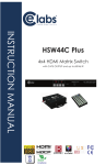
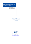
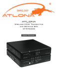
1
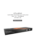
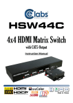
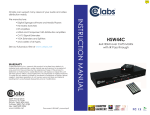
AtlonA
4x4 HDMI over CAT5 Matrix with
IR Control Path
AT-HD44M-SR
User Manual
TABLE OF CONTENTS
1. Introduction
..................................................
1
2. Features
..................................................
1
3. Specification
..................................................
2
4. Package Contents
..................................................
3
5. Connection Diagram
..................................................
3
6.1. AT-HD44M-S ..................................................
4
6.2. AT-HD44M-R
..................................................
5
7. DIP Switch
..................................................
6
8.1. IR Cables
..................................................
7
8.2. IR Sockets
..................................................
7
8.3. Definition of IR Earphone Jack
..................................................
7
8.4. Supported IR Data Format
..................................................
8
9. Hardware Installation
..................................................
9
6. Panel Descriptions
8. IR Control Path
10. Operation and IR Control
10.1. Source Side
.................................................. 10
10.2. Display Side
.................................................. 11
11. RS-232 Serial Port Control
.................................................. 12
12. Firmware Update
.................................................. 13
13. Notice
.................................................. 15
14. Safety Information
.................................................. 16
15. Warranty
.................................................. 17
INTRODUCTION
The AT-HD44M-SR 4x4 HDMI over CAT5 Matrix with IR Control Path provides the most flexible
and cost effective solution in the market to route high definition video sources plus multi-channel (up to 7.1-channel) digital audio from any of the four HDMI sources to the remote displays
at the same time. Through low cost CAT5/5e LAN cables, not only high quality video and audio
can be transmitted to the display sites, but also users can switch among 4 HDMI sources using
the push button or remote control. With single power design at the source site, each remote
module is easily installed without power supply. Furthermore, the built-in IR extension function
makes users at display site access the DVD player, PS3 or any HDMI equipped devices directly!
FEATURES:
• State-of-the-art Silicon Image (founder of HDMI) chipset embedded for upmost compatibility
and reliability
• HDMI 1.2a compliant
• HDCP compliant
• Allows any source to be displayed on multiple displays at the same time
• Allows any HDMI display to view any HDMI source at any time
• Supports 7.1 channel digital audio
• Supports default HDMI EDID and learns the EDID of displays
• The matrix master can switch every output channels to any HDMI inputs by push button, IR
remote control, or RS-232 control
• Allows controlling local HDMI sources such as DVD and TiVo by IR extender through control
path at remote receiver
• Allows to control main matrix center through control line at remote receiver
• Extends video signal up to 35m (115 feet) over CAT5e at 1080p
• Easy installation with rack-mounting and wall-mounting designs for master and receiver respectively
1
SPECIFICATIONS
Technical
Role of usage
AT-HD44M-S
AT-HD44M-R
True 4x4 matrix & transmitter [TX]
Receiver [RX]
HDMI compliance
HDMI 1.2a
HDCP compliance
Yes
Video bandwidth
Single-link 165MHz [4.95Gbps]
Video support
480i / 480p / 720p / 1080i / 1080p60
Audio support
Surround sound (up to 7.1ch) or stereo digital audio
Transmission
Full HD (1080p): 35m (115ft) [CAT5e] / 40m (130ft) [CAT6]
HD (720p/1080i): 50m (165ft) [CAT5e] / 55m (180ft) [CAT6]
Equalization
N/A
8-level digital control
Input TMDS signal
1.2 Volts [peak-to-peak]
Input DDC signal
5 Volts [peak-to-peak, TTL]
ESD protection
[1] Human body model — ±15kV [air-gap discharge] & ±8kV [contact discharge]
[2] Core chipset — ±8kV
PCB stack-up
4-layer board [impedance control — differential 100
Input
; single 50
]
4x HDMI; 1x RS-232
1x RJ-45 TMDS; 1x RJ-45 DDC; 1x IR socket for IR receiver
Output
4x RJ-45 TMDS; 4x RJ-45 DDC;
5x IR socket for IR emitter
1x HDMI
HDMI Input selection
Push button / IR remote / RS-232
Push button / IR remote
HDMI source control
Controllable through IR control path from IR receiver at receiver sites
Electro-optical characteristics: = 25o / Carrier frequency: 38kHz
IR remote control
HDMI connector
Type A [19-pin female]
RJ-45 connector
WE/SS 8P8C with 2 LED indicators [TMDS & DDC channels]
RS-232 connector
DE-9 [9-pin D-sub female]
Earphone jack for IR emitter cable
[IR Main] All sources IR control
[IR1~IR4] Individual channel IR control
3.5mm connector
DIP switch [for MA-5144 only]
Mechanical
[SW1~SW4] 2-pin for EDID, audio mode & safe mode
[SW Main] 4-pin operation mode & firmware update
AT-HD44M-S
AT-HD44M-R
Housing
Dimensions
(L x W x H)
Relative humidity
Model
340 x 110 x 44mm [1’1.4”x4.3”x1.7”]
Package
Model
570 x 580 x 260mm [1’10.5”x1’10.9”x10.2”]
1220g [2.7 lbs]
Package
Fixedness
Power supply
Power consumption
85 x 90 x 25mm [3.3”x3.5”x1”]
545 x 230 x 110mm [1’9.5”x9.1”x4.3”]
Carton
Weight
Earphone jack for IR receiver cable
[IR] Receives IR control
180g [6.3 oz]
3.2 kg [7.0 lbs]
1U rack-mount with ears
Wall hanging holes
Wall-mount with screws
5V 6A DC
Not necessarily required1
20 Watts [max]
Operation temperature
Storage temperature
Relative humidity
1 Watt [max] (provided by MA-5144)
o
0~40 C [32~104o F]
-20~60o C [-4~140o F]
20~90% RH [no condensation]
1
The AT-HD44M-S has been tested extensively and found that it doesn’t require external power supply. If in rare situation you find it cannot
work with the AT-HD44M-R, please use any +5V power adapter to plug in the power jack and see if it can work. If not, please contact your
technical support for further service.
2
PACKAGE CONTENTS:
1. 1x AT-HD44M-S
2. 1x IR emitter cable1
3. 2x Rack-mounting ears
4. 1x IR remote1
5. 1x User Manual
6. 4x AT-HD44M-R
7. 4x IR receiver cable
8. 8x Wall-mounting screws
9. 1x 5V 6A power adapter
1
Additional IR remote control and IR emitter cable can be purchased as optional accessories to control the HDMI
sources located separately.
CONNECTION DIAGRAM
PS3
Blu-Ray DVD
HDMI
Cable
STB
HDMI Camera
HDMI
Cable
HDMI Cable
HDMI Cable
AT-HD44M-S
Cat5e Cable
AT-HD44M-R
Cat5e Cable
Cat5e Cable
AT-HD44M-R
HDMI Cable
AT-HD44M-R
HDMI Cable
Cat5e Cable
AT-HD44M-R
HDMI Cable
HDMI Cable
IR Controller
HDTV
HDTV
3
HDTV
HDTV
PANEL DESCRIPTIONS
AT-HD44M-S
Front Panel
1. Power: Power indicator LED
2. IR: IR receiver
3. Input: Input source indicator LED
4. HP1–HP4: Connection status indicator LED for each output channel
5. Port1–Port4: Input source channels mapping LED for each output channel
6. Port1 Select–Port4 Select: Push button for selecting input channel
Rear Panel
7. ON–OFF: Power ON/OFF
8. RS-232: RS-232 control port
9. +5V DC: 5V DC power jack
10. SW Main: DIP switches (see DIP Switch section in p.7)
11. SW1–SW4: DIP switch (see DIP Switch section in p.7)
12. IN1–IN4: HDMI inputs
13. IR1–IR4: IR extender jacks for individual HDMI source control
14. OUT1–OUT4: RJ-45 TMDS/DDC outputs for each output channel
15. IR Main: IR extender jack for all HDMI source control (default socket for IR emitter)
4
AT-HD44M-R
Front Panel
IN: Push button for switching input source channel in sequential order
1. EQ: Adjust the 8-level equalization control for HDMI signals. 0 – 7 = strongest – weakest. It is recommended to switch from 7 to 0 to find the
optimal visual experience.
2. Source LED: Indicate input source
3. HDMI Out: Connect to HDTV with a HDMI cable
4. IR: Plug in IR receiver cable
Rear Panel
6. +5V DC: 5V power jack (optional*)
7. TMDS: RJ-45 input for TMDS channel
8. DDC: RJ-45 input for DDC channel
*AT-HD44M-R has been tested extensively and found that it doesn’t require external power supply. If in rare situation you find it cannot work
with the AT-HD44M-S, please use any +5V power adapter to plug in the power jack and see if it can work. If not, please contact your technical
support for further service.
5
DIP SWITCH
SW1-SW4 for EDID/Audio
DIP Switch Position
Pin#1
Video
Audio
Description
Pin#2
OFF
OFF
1080p
Stereo1
Default Mode2 – 1080p & stereo audio output for most HDTVs
OFF
ON
720p
1080i
Stereo
Safe Mode3 – Enforce the system output at 720p/1080i video and
stereo audio for basic compatibility among HDTVs
ON
OFF
Bypass4
Bypass
EDID Learning Mode5 – for learning EDID from the display while
playing any received HDMI audio format
ON
ON
Bypass
Stereo
EDID Learning & Stereo Mode5 – for learning EDID from the
display while enforcing stereo output if any HDTV cannot play
surround sound normally
Note:
1
2
If the HDTV shows video but without audio, please try to set audio mode to stereo.
Factory default of SW1-SW4: Pin#1-OFF
& Pin#2- OFF
for 1080p with stereo.
3
If you encounter any unsolved audio/video output problem during system installation, please turn any SW1-SW4
to Pin#1-OFF
& Pin#1-ON
, for safe mode to enforce the most compatible 720p stereo output for system
check.
4
Bypass means the matrix will maintain playing the original format of HDMI signals in video and audio. By
setting at this mode, the users may encounter compatibility issue among different kinds of HDMI sources and
displays. If you cannot get the audio and/or video output normally at the system installation, please change the
DIP switch setting to default mode or even safe mode to verify the functionality of the device.
5
Set Pin#1 at ON
first then connect the HDMI Input to HDTV through a HDMI cable. Wait for 20 seconds. The
EDID learning procedure will be finished. If you want to learn the EDID from another HDTV, you must set Pin#1
at OFF
first and repeat this procedure.
SW Main for firmware update (for technical support only)
DIP Switch Position
Pin#1
Normal Operation Mode
Firmware Update Mode
Pin#2
Pin#3
Pin#4
6
OFF
OFF
ON
OFF
7
ON
ON
OFF
OFF
Note:
6
Factory default for SW Main: Pin#1-OFF
, Pin#2-OFF
THIS SETTING AT ANYTIME FOR REGULAR USE!
7
Sequence for firmware update
1. Power off the AT-HD44M-SR.
2. Set the DIP switch position to Firmware Update Mode.
3. Power on the AT-HD44M-SR.
4. Power off the AT-HD44M-SR.
5. Set the DIP switch position to Normal Operation Mode.
6. Power on the AT-HD44M-SR.
6
, Pin#3-ON
, Pin#4-OFF
. PLEASE MAINTAIN
IR CONTROL PATH:
IR Cables
IR Emitter Cable
IR Receiver Cable
IR Sockets
AT-HD44M-S
IR Main: The default location for IR emitter extension cable to transmit all IR command signals received from any
of the four remote receivers to all of the HDMI sources.
IR1: IR emitter extension cable connected here can only transmit IR command signals from the remote receivers
that are setting at the input channel 1.
IR2: IR emitter extension cable connected here can only transmit IR command signals from the remote receivers
that are setting at the input channel 2.
IR3: IR emitter extension cable connected here can only transmit IR command signals from the remote receivers
that are setting at the input channel 3.
IR4: IR emitter extension cable connected here can only transmit IR command signals from the remote receivers
that are setting at the input channel 4.
AT-HD44M-R
IR: IR receiver cable connected here can receive all IR command signals from the IR remote controls of MA5144C and all other HDMI source machines.
Definition of IR Earphone Jack
IR Emitter
IR Receiver
Note: You can buy any IR extension cables in the market that are compatible to the definition of the IR sockets for
the matrix if necessary for replacement use.
7
Supported IR Data Format
Data Format
NEC
RC5
TOSHIBA MICOM CODE
GRUNDIG CODE
SONY 12 BIT CODE
SONY 15 BIT CODE
SONY 20 BIT CODE
RCA CODE
RCM CODE
MATSUSHITA CODE
MITSUBISHI CODE
ZENITH CODE
JVC CODE
M50560-001P
MN6125H
MN6125L
MN6014_C5D7
MN6014-C6D6
MC14457P
LC7464(AHEA)
GEMINI_CM
Suitable
+
+
+
+
+
+
+
Not Recommended
+
+
+
+
+
+
+
+
+
+
+
+
+
+
8
HARDWARE INSTALLATION:
AT-HD44M-S as master:
1. Connect all sources to HDMI Inputs on the 4x4 HDMI over CAT5 matrix master AT-HD44M-S
2. Connect each DDC output on the AT-HD44M-S to respective DDC input on the remote receiver AT-HD44M-R
3. Connect each TMDS output on the AT-HD44M-S to respective TMDS input on the remote
receiver AT-HD44M-R
4. Connect IR emitter cable to the AT-HD44M-S and direct the IR emitter to the build-in IR receiver of the sources
5. Connect the +5V 6A DC power supply to the AT-HD44M-S
6. Power on all HDMI sources
7. Power on the AT-HD44M-S
AT-HD44M-R as receiver:
1. Connect each HDMI output to HDMI displays
2. Connect the TMDS input on the AT-HD44M-R to the TMDS output on the AT-HD44M-S
3. Connect the DDC input on the AT-HD44M-R to the DDC output on the AT-HD44M-S
4. Connect IR receiver cable and place the IR receiver at the appropriate position that can receive the IR signals sent from the users
5. Use push button to adjust the EQ until the picture and sound are clear
9
OPERATION and IR CONTROL
Source Side
Method A: Push Button
Push the switch button on the front panel, the source will be sequentially changed.
Method B: IR Remote Control
a. Please press
to enter IR control mode
Note: If AT-HD44M-S receives the IR commands, the LED will flash. If not, try again.
b. Decide which output port to be controlled by pressing F1 to F4, and wait a few
seconds for audio/video of next channel coming out after the channel switch command is
sent.
Note: If the setting is correct, the corresponding LED will flash. If not, please press output port select
button or repeat step (a) and (b).
F1
F2
F3
F4
HDMI output #1
HDMI output #2
HDMI output #3
HDMI output #4
c. Use
or
keys to select input source,
and wait a few seconds for audio/video of next
channel coming out after the channel switch
command is sent.
Note: If the setting is correct, the corresponding LED will flash.
If there is no response, please wait until the LED stops flashing,
and try again.
Left button to switch channels in ascending order (1, 2, 3, 4, 1,...)
Right button to switch channels in descending order (1, 4, 3, 2, 1,…)
10
Display Side
Method A: Push button
Push the switch buttons of respective output channels then the output channel will
switch from HDMI source 1 to source 4 in sequential order, and wait a few seconds for
audio/video of next channel coming out after the channel switch command is sent.
Method B1: IR remote control for switching input channels
Channel select switch must be set to zero.
a. Press Power on button to enable IR control function.
Note: AT-HD44M-R receives the IR command, the LED will flash. If not, try again.
b. Press hot key for input source:
F1
F2
F3
F4
HDMI output #1
HDMI output #2
HDMI output #3
HDMI output #4
Method B2: IR remote control for controlling
the HDMI sources
Users can use the corresponding IR remote to control
respective DVD player or any HDMI compliant devices
including AT-HD44M-S itself with IR control at any
display site.
11
RS-232 SERIAL PORT CONTROL
RS-232 transmission Format
Bit Rate: 9600
Data Bits: 8
Parity: None
Stop bits: 1
Flow Control: None
Set Command
The command set includes:
A1~A4 setup the output of HP1
B1~B4 setup the output of HP2
C1~C4 setup the output of HP3
D1~D4 setup the output of HP4
VR send back firmware version => V3.01b
ST send back device status
[Input1 ON/OFF; Input2 ON/OFF; Input3 ON/OFF; Input4 ON/OFF;
Output1: 1~4; Output2: 1~4; Output3: 1~4; Output4:1~4]
P0 & P1 are not supported for At-HD44M because it can only be manually turned ON or OFF.
All other non-supported commands will show “Error Command”
Status Command
Command Code
Data
Check SUM
Response
Get Status
Check SUM
Description
Status
0x05 0x4d 0x4f 0x44
0xe5
0xaa 0x06 0x4d 0x41
0x51 0x44
0x29
Get Device Type (MA5144)
0x07 0x4d 0x41 0x53 0x57
0x04
0x43
0xaa 0x3 0x01~0xff
0x04~0x02
Get Device ID
0x08 0x4d 0x41 0x51 0x44
*0x01~0xFF 0x01
0x2e~0x2c
0xaa 0x06 port1 port2
port3 port4
0x06 +
port1~port4
Get Source Mapping of
Output Port
0x08 0x4d 0x41 0x51 0x44
*0x01~0xFF 0x04
0x30~0x2e
0xaa 0x08 0x56 0x33
0x2e 0x30 0x31 0x61
0x81
Software Version
V.3.01a
Check sum:
Check sum = (Data value sum)%256 The check sum of response is not included 0xaa.
0x01 ~ 0xFF:
This data is device ID. The Device ID saved in the device, if the device ID of the controlled device is 0xff , the device will ignore its own ID and carry out the commands.
12
FIRMWARE UPDATE
Warning!
There could be unexpected consequences resulted from inappropriate firmware update
operation. Please do it with caution.
1.
Please unzip the Matrix_Firmware_Update.zip into your designated folder.
2.
Please turn off the power of the MATRIX and set DIP location of [SW Main] at
Pin#1-ON , Pin#2-ON , Pin#3-OFF , & Pin#4-OFF .
3.
Please execute the file Matrix_Firmware_Update.exe
4.
In the pop-up window, at [Select Chip], please select W78E365.
5.
In the pop-up window, at [Select File], please choose the BIN file in the designated
folder, as shown in the picture.
6.In the pop-up window, please select the [File Format] to Binary.
13
7. Please make sure your PC has direct connection to the RS-232 port of the MATRIX, as
shown in the picture (left), that in [Communication Setting] the onlne status should be “Wait to
connect”. If the RS-232 connection is not firmly established, you will see the online status is
“Disconnect.” If so, please check the RS-232 connection until the online status becomes “Wait
to Connect.”
8. Please turn on the MATRIX. The firmware update process will automatically initiate.
9. The firmware update process is successful if you see the [Information] window pops up to
inform you that the process is complete. If you see the [Error] window pops up, please turn off
the MATRIX and turn it on again. If necessary, please redo the whole sequences 1-9.
10. The message “Program: OK!” means the firmware update process is successful. If you see
the [Error] window pops up after the message [Program: OK!], please ignore it.
11. Turn off MATRIX. Set DIP location of [SW Main] at Pin#1-OFF
Pin#3-ON , & Pin#4-OFF .
12. Turn the MATRIX back on and return to normal operation.
14
, Pin#2-OFF
,
NOTICE
1. If the DVI or HDMI device requires the EDID information, please use EDID Reader/Writer to
retrieve and provide DVI/HDMI EDID information.
2. All HDMI over CAT5 transmission distances are measured using Belden 1583A CAT5e
125MHz LAN cable and ASTRODESIGN Video Signal Generator VG-859C.
3. The transmission length is largely affected by the type of LAN cables, the type of HDMI
sources, and the type of HDMI display. The testing result shows solid LAN cables (usually
in bulk cable 300m/1000ft form) can transmit a lot longer signals than stranded LAN cables
(usually in patch cord form). Shielded STP cables are better suit than unshielded UTP cables. A solid UTP CAT5e cable shows longer transmission length than stranded STP CAT6
cable. For long extension users, solid LAN cables are your only choice.
4. EIA/TIA-568-B termination (T568B) for LAN cables is recommended for better performance.
5. To reduce the interference among the unshielded twisted pairs of wires in LAN cable, you
can use shielded LAN cables to improve EMI problems, which is worsen in long transmission.
6. Because the quality of the LAN cables has the major effects in how long transmission distance will be made and how good is the received display, the actual transmission length is
subject to your LAN cables. For resolution greater than 1080i or 1280x1024, a CAT6 cable is
recommended.
7. If your HDMI display has multiple HDMI inputs, it is found that the first HDMI input [HDMI
input #1] generally can produce better transmission performance among all HDMI inputs.
8. The AT-HD44M-SR has been tested extensively and found that it doesn’t require external
power supply. If in rare situation you find it cannot work with the AT-HD44M-SR, please use
any +5V power adapter to plug in the power jack and see if it can work. If not, please contact
your technical support for further service.
9. Additional IR remote controls and IR emitter cables can be purchased as optional accessories to control the HDMI sources located separately.
Performance Guide for HDMI over LAN Cable Transmission
Performance rating
Wiring
Shielding
Solid
Unshielded (UTP)
Shielded (STP)
Stranded Unshielded (UTP)
Shielded (STP)
Termination
CAT5
***
***
*
*
Type of LAN cable
CAT5e
****
***
**
*
CAT6
*****
****
**
**
Please use EIA/TIA-568-B termination (T568B) at any time
15
SAFETY INFORMATION
Avoid excessive humidity, sudden
temperature changes or temperature
extremes.
Safeguards
To reduce the risk of electric shock, do not
expose this product to rain or moisture.
If the wall plug does not fit into your local
power socket, hire an electrician to replace
your obsolete socket.
Do not modify the wall plug.
Doing so will void the warranty and safety
features.
Keep this product away from wet locations
such as bathtubs, sinks, laundries, wet
basements and swimming pools.
Use only accessories recommended by
ATLONA to avoid fire, shock or other
hazards.
Unplug the product before cleaning. Use
a damp cloth for cleaning. Do not use
cleaning fluid or aerosols, which could
enter the unit and cause damage, fire or
electrical shock. Some substances may
also mar the finish of the product.
This equipment should be installed near
the socket outlet and the device should
be easily accessible in case it requires
disconnection.
Precautions
Never open or remove unit panels or make
any adjustments not described in this
manual. Attempting to do so could expose
you to dangerous electrical shock or other
hazards. It may also cause damage to your
AT-HD44M-SR. Opening the product will
void the warranty.
FCC Regulations state that any
unauthorized changes or modifications to
this equipment not expressly approved by
the manufacturer could void the
user’s authority to operate this
equipment.
Operate this product using only the
included external power supply. Use of
other power supplies could impair
performance, damage the product or cause
fires.
In the event of an electrostatic discharge,
this device may automatically turn off. If this
occurs, unplug the device, and plug it back
in.
Protect and route power cords so they will
not be stepped on or pinched by anything
placed on or against them. Be especially
careful of plug-ins, or cord exit points from
this product.
16
Do not attempt to service the unit. Instead
disconnect it and contact your Authorized
ATLONA reseller or contact ATLONA
directly.
WARRANTY
LIMITED ONE-YEAR WARRANTY
ATLONA by Lenexpo Electronics warrants only to the initial purchaser of this product for a period of one year from
the date of purchase from an Authorized ATLONA Reseller, the product will be free of electrical and mechanical defects that materially affect the products operation as described in this users manual. Within this period, ATLONA will,
at it’s sole option, repair or replace any components, which fail of normal use or refund the net original price.
DISCLAIMER OF WARRANTY
ALL IMPLIED WARRANTIES OF MERCHANTABILITY OR FITNESS FOR A PARTICULAR PURPOSE ARE LIMITED TO ONE YEAR FROM PURCHASE; ALL OTHER EXPRESS OR IMPLIED CONDITIONS, REPRESENTATIONS
AND WARRANTIES, INCLUDING ANY IMPLIED WARRANTY OF NON INFRIGEMENT, ARE DISCLAIMED. Some
jurisdictions do not allow limitations on how long an implied warranty lasts, so the above limitation may not apply to
you. This warranty gives you specific legal rights, and you may also have other rights, which vary by jurisdiction.
LIMITATION OF LIABILITY
TO THE EXTENT NOT PROHIBITED BY LAW, IN NO EVENT WILL ATLONA OR ITS SUPPLIERS BE LIABLE FOR
ANY LOST REVENUE, PROFIT OR DATA, OR FOR SPECIAL, INDIRECT, CONSEQUENTIAL, INCIDENTAL, OR
PUNITIVE DAMAGES, HOWEVER CAUSED REGARDLESS OF THE THEORYOF LIABILITY, ARISING OUT OF
OR RELATED TO THE USE OF OR INABILITY TO USE THE PRODUCT, EVEN IF ATLONA HAS BEEN ADVISED
OF THE POSSIBILITY OF SUCH DAMAGES. IN NO EVENT ATLONA’S LIABILITY TO YOU, WHETHER IN CONTRACT, TORT (INCLUDING NEGLIGENCE),OR OTHERWISE, EXCEED THE AMOUNT PAID BY YOU FOR THE
PRODUCT. The foregoing limitations will apply even if any warranty or remedy provided to you fails its essential
purpose. Some jurisdictions do not allow the exclusion or limitation of incidental or consequential damages, so the
above limitation of or exclusion may not apply to you.
Disclaimer
This document is provided for technical information for the user. It does not create any warranty with respect to the
product, and does not modify or enhance the terms of the warranty that may accompany this product.
ATLONA reserves the right to modify the information in this document as necessary.
ATLONA holds no responsibility for any errors that may appear in this document. Customers should take appropriate
action to ensuretheir use of the product does not infringe upon any patents. ATLONA respects valid patent rights of
third parties.
Trademarks and Copyrights All other product names or marks referenced herein are trademarks or registered trademarks of their respective owners.
ATLONA
2151 O’toole Ave, Ste D
San Jose CA 95131
Toll Free: 1-877-536-3976
International: 408-954-8782
FAX: 408-954-8792
Website: www.atlona.com
E-MAIL: [email protected]
17