1
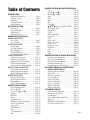
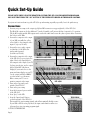
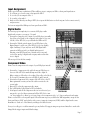
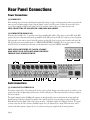
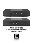
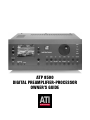
ATP 8500
DIGITAL PREAMPLIFIER-PROCESSOR
OWNER’S GUIDE
ATI
Amplifier Technologies
This product is manufactured under license from Dolby Laboratories Licensing Corporation.
“Dolby”, the Double-D symbol, “Dolby Digital” and “Pro Logic”
are trademarks of Dolby Laboratories Licensing Corporation.
DTS is a trademark of Digital Theatre Systems, Inc.
Page 2
▼
INTRODUCTION
Functional Description ........................ Page 4
Software Version ................................. Page 4
Unpacking .......................................... Page 4
Safety Instructions .............................. Page 5
Rack Mounting ................................... Page 5
QUICK SET-UP GUIDE
Connections ....................................... Page 6
Input Assignment ............................... Page 7
Digital Audio ...................................... Page 7
Component Video ................................ Page 7
REAR PANEL CONNECTIONS
POWER CONNECTIONS
Power Inlet ......................................... Page 8
Power Switch ..................................... Page 8
AUDIO CONNECTIONS
Analog Inputs ..................................... Page 8
Tape Input/Output .............................. Page 9
Record Outputs ................................... Page 9
Zone Audio Output .............................. Page 9
7.1 Channel Inputs & Outputs ............... Page 9
VIDEO CONNECTIONS
Composite Video Inputs ...................... Page 10
Composite Video Outputs ................... Page 10
Composite Video Zone Outputs ........... Page 10
S-Video Inputs & Outputs ................... Page 10
Component Video Inputs/Outputs ....... Page 10
DIGITAL AUDIO CONNECTIONS
Coaxial Digital Audio Inputs ................ Page 11
Optical Digital Audio Inputs ................ Page 11
Optical Digital Audio Outputs .............. Page 11
OTHER CONNECTIONS
Balanced Audio Inputs ....................... Page 11
RS 232 Control Interface ..................... Page 11
IR Input/Output ................................ Page 11
Remote Trigger Outputs ..................... Page 11
FRONT PANEL CONTROLS
Power Standby Switch ....................... Page 12
Preview On/Off ................................. Page 12
Source Select ▲ and ▼ ..................... Page 13
Display ............................................. Page 13
Exit/Enter ......................................... Page 13
Menu ............................................... Page 13
Volume Control ................................. Page 13
Headphone Volume and Input ............ Page 14
Source Select Buttons ........................ Page 14
Input Search ..................................... Page 14
Audio Monitor 1 ................................ Page 14
Zone 2 .............................................. Page 14
7.1 Channel Input ............................. Page 14
Mute ................................................ Page 14
▼
Table of Contents
REMOTE CONTROL HANDSET OPERATIONS
Power .................................................. Page 16
Volume ▲ and ▼ ................................ Page 16
Channel ▲ and ▼ ............................... Page 16
Mute ................................................... Page 16
Guide .................................................. Page 16
Menu .................................................. Page 16
Exit ..................................................... Page 16
Select/Play............................................ Page 16
▲,▼, ▲,▼ Up, Down, Right, Left Keys ... Page 17
Direct Access Keys ................................. Page 17
Tape Monitor ....................................... Page 17
7.1 CH ................................................. Page 17
B-Bass (Bass Mix) ................................. Page 17
Compress ............................................. Page 17
Noise ................................................... Page 18
Mode + and –........................................ Page 18
Subwoofer + and – ................................ Page 18
Center + and – ...................................... Page 18
Surround + and – ................................. Page 18
Brightness............................................ Page 18
Lock .................................................... Page 18
Zone ................................................... Page 18
Light ................................................... Page 18
REMOTE CONTROL LEARNING OPERATIONS
Learning a New Command .................... Page 19
Erase a Learned Command .................... Page 19
Erase All Learned Commands ................ Page 20
Volume Punch Through ........................ Page 20
Programming the Macro Buttons ........... Page 21
ON-SCREEN DISPLAY AND FRONT PANEL
DISPLAY SETUP MENUS
Accessing the Setup Menus .................... Page 22
Main Menu .......................................... Page 22
Tone Controls Menu ............................. Page 23
Level Setup Menu.................................. Page 23
Delay Setup Menu ................................. Page 24
Speaker Setup Menu ............................. Page 25
Source Setup Menu ............................... Page 26
Display Setup Menu .............................. Page 27
Trigger Setup Menu .............................. Page 27
CUSTOMER SUPPORT
Frequently Asked Questions ................... Page 28
Trouble Shooting Guide ........................ Page 30
Specifications ....................................... Page 31
General Maintenance and Service .......... Page 32
Warranty ............................................. Page 33
Obligation To Make Changes.................. Page 33
Save For Your Reference ........................ Page 35
Page 3
Introduction
Functional Description
Thank you for selecting ATI’s ATP 8500 Digital Preamplifier-Processor for your audio and video home theater.
The ATP 8500 is the center of a high-end cinema and audio system. The ATP 8500 decodes Dolby Digital, DTS and
Dolby Pro Logic. Naturally, the ATP 8500 can also function as a High-End stereo preamplifier, and the digital signal
processing and conversion can be bypassed. The 7.1 channel input is provided with comprehensive volume control
facilities. This ensures that ATP 8500 will remain compatible with new multi-channel formats to appear in the future.
For audio, the ATP 8500 accepts up to six digital input sources, ten line level input sources, a tape loop and two
additional record outputs. For video, it has six S-Video and composite inputs, S-Video and composite monitor outputs,
S-Video and composite video record outputs and an S-Video monitor output without OSD (On Screen Display).
For Component Video, the ATP 8500 offers 3 sets of inputs and one set of outputs. If you are using all three types of
video (composite, S-VHS, and component), you need to connect each output from the ATP 8500 to the appropriate
connectors on the rear of your TV or monitor. You then switch between video formats with your TV’s remote (or a
“smart system” remote control).
The ATP 8500 has two main modes of function: In the normal function mode, the ATP 8500 automatically senses the
type of the incoming signal and selects the mode that gives optimal reproduction quality. The user can switch off the
automatic selection and select different post-processing modes for the incoming signals. These modes are stereo, Dolby
Pro-Logic, mono down-mixing and four Music Modes: Natural, Concert, Club and Party. If desired, the user can bypass
the digital section of ATP 8500 and connect, for example, a stereo source to the Left and Right channels of the balanced
XLR inputs.
System integration options are provided by the three 12VDC trigger outputs and one trigger input to control external
equipment and by communication with a PC or home automation system via the RS 232 serial interface (DB-9 connector).
Software Version
In order to verify which version software you have installed in the ATP 8500, push and hold the front panel power
button for a few seconds and the software version number will appear under the “ATI” name on the LCD.
Unpacking
The ATP 8500 has been carefully inspected, tested and packed before leaving the factory. Immediately upon receiving
your preamplifier-processor, inspect the carton for evidence of mishandling during shipment. Then, carefully unpack
the preamplifier-processor and inspect it for damage. Please save the shipping carton and all inner packing materials
in the event that the preamplifier-processor needs to be shipped for service or moved to a new location. Should you
discover that the preamplifier-processor has been damaged during shipping, please contact your dealer or ATI
immediately and request the name of the carrier so a written claim can be made.
THE RIGHT TO A CLAIM AGAINST A PUBLIC CARRIER CAN BE FORFEITED IF THE CARRIER IS NOT NOTIFIED
PROMPTLY IN WRITING AND IF THE SHIPPING CARTON AND PACKING MATERIALS ARE NOT AVAILABLE
FOR INSPECTION BY THE CARRIER. SAVE ALL PACKING MATERIALS UNTIL THE CLAIM HAS BEEN SETTLED.
Page 4
Safety Instructions
NOTE FOR INSTALLATION: The ATP 8500 generates a certain amount of heat and requires ventilation. Do not place it
on a soft surface such as a rug into which it could sink. You should also avoid a built-in installation place such as a
bookcase or a rack unless you can provide proper ventilation for ATP 8500. Do not use this unit near water: for
example, near a bathtub, washbowl, kitchen sink, laundry tub, in a wet basement, or near a swimming pool. The unit
should be situated away from heat sources such as radiators, heat registers, stoves, or other devices (including
power amplifiers) that produce heat.
WARNING: MOISTURE IS DANGEROUS FOR THIS DEVICE AND FORMS A HAZARD OF FIRE OR ELECTRIC
SHOCK. IF LIQUID IS ACCIDENTALLY SPILLED ON IT, IMMEDIATELY SHUT OFF ITS POWER AT THE WALL
OUTLET BY UNPLUGGING THE AC POWER CORD. ALLOW SUFFICIENT TIME FOR COMPLETE EVAPORATION
BEFORE USING THE PREAMPLIFIER AGAIN. IF THE LIQUID IS ANY OTHER THAN WATER AND/OR
ALCOHOL, DO NOT USE THE DEVICE BEFORE A QUALIFIED SERVICE TECHNICIAN HAS EXAMINED IT.
DANGER: Do not open the cover, or try to modify or repair the preamplifier yourself. All servicing must be done by a
qualified technician.
IMPORTANT: USE A DAMP CLOTH TO CLEAN THE MONITOR. NEVER USE ABRASIVES OR SOLVENTS ON
THE MONITOR. NEVER SPRAY LIQUIDS DIRECTLY ON THE MONITOR.
Read all the safety and operating instructions before connecting or using this unit. All warnings on the unit and in this
operating manual should be adhered to. All operating and use instructions should be followed.
The unit should be connected to a power-supply outlet only of the voltage and frequency marked on its rear panel.
The power-supply cord should be routed so that it is not likely to be walked on or pinched, especially near the plug,
convenience receptacles, or where the cord exits from the unit. The power-supply cord of the unit should be unplugged
from the wall outlet when it is to be unused for a long period of time. To prevent electric shock, do not use the polarized
plug with an extension cord, receptacle or other outlet unless the blades can be fully inserted to prevent blade exposure.
The unit should be serviced by qualified service personnel when:
A. The power cord or the plug has been damaged; or
B. Objects have fallen, or liquid has been spilled, into the unit; or
C. The unit has been exposed to rain, or liquids of any kind; or
D. The unit does not appear to operate normally, or exhibits a marked change in performance; or
E. The device has been dropped, or the enclosure damaged.
Rack Mounting
Your preamplifier-processor may be mounted in a standard 19-inch rack by using the optional Rack Mount Panel.
CAUTION: THE RACK MOUNT PANEL CANNOT SUPPORT THE WEIGHT OF YOUR PREAMPLIFIERPROCESSOR. BE SURE TO MOUNT THE UNIT ON A STRONG, WELL-SUPPORTED SHELF.
Page 5
Quick Set-Up Guide
PLEASE NOTE: WHEN USING THE REMOTE TO CONTROL THE ATP 8500 PREAMPLIFIER-PROCESSOR,
YOU MUST FIRST PRESS THE “AVC” BUTTON IN THE UPPER LEFT CORNER OF THE REMOTE CONTROL .
If you just can’t wait and want to get the ATP 8500 up and running as quickly as possible, here’s the quickest way:
Connections
1. Connect your power amp to the outputs (gold plated RCA connectors on upper right side) of the ATP 8500.
The RR & LR outputs are for the additional 7.1 mode. Normally, you’ll just use the first 6 outputs for 5.1 operation.
FYI, the RCA outputs and the XLR outputs can be used at the same time because they have separate driver electronics.
Pin 2 is hot on the XLRs.
2. Connect the composite video output
of your VCR (normally the yellow
colored jack) to the composite video
input #1 (top row, left side).
3. Connect the stereo audio outputs
(red & white) of the VCR to the
analog audio inputs #1
(bottom row, left side).
4. Connect the composite video output
5-CHANNEL AMPLIFIER
of the ATP 8500 (top row, just to the
right of the 6 video input jacks) to
the composite video input of your TV.
You have two choices: use the output
labeled “Mon OSD” (On Screen
Display) if you want to the see the
menu and status display on your TV.
Use the output jack labeled MON if
you don’t want to see the menu.
Make certain your TV is set to
monitor composite video input.
ATP 8500
5. Turn on the rear panel power
switch of the ATP 8500.
6. Turn on the power amp.
7. Press the front panel power switch
of the ATP 8500.
8. Press “play” on the VCR.
VCR
9. Press the “Input Search” button
TELEVISION
on the front panel of the ATP 8500.
This searches for any incoming signals, and will automatically find the source.
If your VCR or DVD is not in play mode, the input search function will not see
it because there is no incoming program signal.
10.TURN UP THE VOLUME!
Page 6
Input Assignment
Want to get a little more sophisticated? Then add these steps to assign your VCR to a front panel input button:
1. Go to Menu, go to Source setup, select input title VCR 1.
2. Go to video, select composite video 1.
3. Go to audio, select audio 1.
4. Back out of the Menu by scrolling to EXIT (do not press the Exit button on the front panel or the remote control),
and press enter.
You’ve now assigned the VCR input to front panel button VCR 1.
Digital Audio
The next step up in complexity is to connect a DVD player with
digital audio output so you can get 5.1 sound:
1. Connect the composite video output of your DVD player (normally
the yellow colored jack) to the composite video input #1 (top row,
left side) of the ATP 8500, as you did with the VCR in at left.
2. Connect the Toslink optical output of your DVD player to the
Optical Input #1 on the rear of the ATP 8500 (top row, slightly
right of mid-way). If you only have an SP/DIF digital audio
connection (RCA type jack), use Digital Audio input #1.
Warning: some DVD players have a switch on the rear panel
to select the analog or digital audio outputs; make certain this
is set to digital.
Follow steps 4-10 in the first example.
DVD PLAYER
Component Video
Want to use the component video output of your DVD player instead?
1. Connect the 3 component video cables from your DVD player to
ATP 8500
the rear of the ATP 8500 marked Component Video Input #1.
Make certain you follow the color coding of the cables or the labels
Pb, Pr, and Y. Sometimes these are called Cb, Cr and Y instead.
2. Connect the Component Video outputs of the ATP 8500 to the TV.
Once again make certain you have the cables connected to the
correct jacks.
3. On your TV, select the component video input.
4. Play a DVD with a Dolby Digital or DTS soundtrack.
5. Press Input Search. If the component video in is not detected, you
TELEVISION
may need to go to the Menu system and tell the ATP 8500 to turn
“on” these inputs. Go to Menu, go to Source Setup, select component video “on”. Now press Input Search again.
Want to set the DVD to a front panel input? Follow the same steps as you did for the VCR assignment, except use the
front panel button “DVD” and select the video source (composite/component/S-VHS) and the digital audio source.
Remember to “back out” of the Menu by scrolling to the Exit selection.
Now you’ve really got to read the manual to get any further. We suggest using an experienced installer to work with
things like the trigger inputs and default settings.
Page 7
Rear Panel Connections
Power Connections
(1) POWER INLET
Before making any connections, check that the mains (AC) voltage or range of voltages printed on the rear panel is the
same as your local mains supply voltage. Plug the female (socket) end of the power cord into the power inlet on the
rear of the preamplifier. Plug the male (plug) end of the cord into a wall socket or an extension power cord.
NOTE: CONNECT THE ATP 8500 ONLY TO A GROUNDED WALL SOCKET.
(2) POWER SWITCH (REAR PANEL)
Press the rocker switch to the “I” position to turn the preamplifier ON and the “O” position to turn it OFF. In the OFF
position, all power is disconnected from the preamplifier. In the OFF position, the ATP 8500 cannot be powered up from
the front panel or the remote control. In the ON position (provided the device receives power from the wall outlet) the
ATP 8500 will power up in standby mode (see FRONT PANEL CONTROLS, STANDBY). If you are not going to be using
the ATP 8500 for an extended period of time, you should turn the rear panel "POWER" switch OFF.
NOTE: ALWAYS SWITCH THE ATP 5800 TO “STANDBY”
MODE (FRONT PANEL SWITCH OFF) BEFORE SWITCHING
THE REAR PANEL POWER SWITCH OFF.
3
8
8
3
4
5
6
7
2
1
Audio Connections
(3) ANALOG INPUTS 1 THROUGH 10
Connect the output cables of the analog audio devices to these sockets. Always connect these inputs, even when you are
going to listen only via digital inputs (such sources as DVD or CD players). This ensures that there is always a signal at
the record outputs.
The signal coming from the ANALOG audio inputs goes through an A/D converter that turns the analog signal into
digital form (A/D=Analog to Digital. The signal is now ready for Dolby Pro Logic decoding or post-processing with
Music Modes. Then the signal is fed to D/A converters and to 7.1 Channel outputs (D/A=Digital to Analog). The signal
you have selected is also fed to the three ANALOG outputs. Note: the balanced stereo input (XLR connectors) can be
routed via the menu system to bypass the A to D conversion and operate completely in the analog domain.
Page 8
(4) TAPE INPUT/OUTPUT
These connectors are for all types of tape recorders, including 3-head types, which allow you to monitor the signal from
the tape at the same time it is being recorded. Connect a stereo cable pair from the TAPE REC output sockets of the preamp
to the LINE IN or RECORD IN sockets of your tape recorder. Connect a second pair of stereo cables from the TAPE PLAY
input sockets to the LINE OUT or PLAY OUT sockets of your tape recorder.Using the TAPE loop you can monitor the
level and quality of the recording at the same time as the recording takes place. You can also use it for connecting
external devices (such as an equalizer) to the signal path. Note: do not use an equalizer across the Tape Loop. Any ANALOG
stereo source you have selected on the ATP 8500 will be automatically fed to the TAPE REC output sockets for recording.
You cannot make a recording from a source that is connected ONLY to the digital inputs or the 7.1 channel inputs.
(5) RECORD OUTPUTS 1 & 2
The REC outputs carry the signal from the currently selected ANALOG stereo source device (except the source connected
to the TAPE PLAY input or the 7.1 CHANNEL INPUT). You can connect these outputs to the inputs of any recording
device. The signal can also be used in a multi-room set-up to feed power amplifiers in other rooms.
(6) ZONE AUDIO OUTPUT
This is an additional stereo output that is routed separately from the primary signal. In other words, you can watch
one video/audio program in the living room, and send a different video/audio signal to the bedroom. Zone 2 sends a
different source from the ATP 8500 to a power amplifier and a pair of loudspeakers that are located in another room.
Note: the video signal follows this Zone 2 audio.
(7) 7.1 CHANNEL INPUTS (LEFT FRONT, CENTER, RIGHT FRONT, LEFT SURROUND, RIGHT SURROUND,
LEFT REAR, RIGHT REAR AND SUBWOOFER)
Connect the audio inline outputs from any multi-channel analog source such as a Super Audio CD (SACD) player or a
DVD-Audio player to these inputs by using up to eight interconnect cables (or four stereo cable pairs). The 7.1 CHANNEL
inputs may be used with stereo, mono, 5.1 channel or 7.1 channel sources.
You can also use these inputs as an “Analog Direct” input if you want to bypass the digital section of ATP 8500.
Note: In this case you cannot use the record outputs.
(8) 7.1 CHANNEL OUTPUTS (LEFT FRONT, CENTER, RIGHT FRONT, LEFT SURROUND, RIGHT SURROUND,
LEFT REAR, RIGHT REAR AND SUBWOOFER)
Connect these outputs to the line inputs of your power amplifiers. The SUB output is normally fed to the low-level Line
Input of an active subwoofer. Alternatively it may feed a passive subwoofer with a separate power amplifier. These 7.1
outputs are available at two different types of connectors:
The deluxe RCA style phono jacks on the upper right of the rear panel.
The balanced XLR connectors running across the center of the rear panel.
Both connectors can be used at the same time because they have two completely separate drive amplifier sections.
In fact, the balanced audio output circuitry of the ATP 8500 is superior to products costing 2-3 times more than the
ATP 8500. As per professional audio standards, pin 2 of the output connector is “hot”. This is also true of the balanced
XLR input connectors.
The LEFT REAR (LR) and RIGHT REAR (RR) outputs are reserved for future surround formats. These outputs carry the
analog signal that is fed to the LEFT REAR and RIGHT REAR 7.1 CHANNEL INPUTS<None> so that ATP 8500 can be
used with an external 7.1 channel analog source connected to the 7.1 channel inputs. In the future it will be possible to
fit the ATP 8500 with hardware/software capable of decoding 7.1 channel digital sources.
Page 9
Video Connections
(9) COMPOSITE VIDEO INPUTS 1 THROUGH 6
These are the default video inputs. Connect the composite video output cables coming from your video sources to these
inputs. Note: Take care to use inputs with the same name for the composite video, S-Video and analog audio cables
from a single source. E.g. cables from a VCR (VideoCassette Recorder) should go to the VCR-VIDEO, VCR COMPOSITE
VIDEO and VCR ANALOG inputs. The composite video signal is selected from these signals, and the signal is fed out
from the COMPOSITE VIDEO record (REC) and monitor (MON) outputs. On Screen Display information is added to the
MON output.
(10) COMPOSITE VIDEO RECORD AND MONITOR OUTPUTS
Connect the Composite Video input of your VCR to the COMPOSITE VIDEO REC output. Connect the Composite Video
input of your display device (TV) to the COMPOSITE VIDEO MON output. The On Screen Display (OSD) information is
present at this output. You can also use the COMPOSITE VIDEO MON output even if there is no composite video source
connected. The S-Video signal you have selected is down-mixed to this output and you can use it for monitoring. Even
on OSD video outputs, the OSD info can be turned off by going to the MENU function and selecting DISPLAY, then
selecting OFF.
(11) COMPOSITE VIDEO ZONE AND MONITOR OUTPUTS (MONITOR WITHOUT OSD)
This is an additional Composite Video and Monitor output. You can use it for example to give a different signal to a TV
located in another room called zone 2. On this Monitor output the On Screen Display (OSD) is not displayed.
(12) S-VIDEO INPUTS 1 THROUGH 6
Connect the S-Video output cables from your video sources to these inputs. Note: Take care to use inputs with the same
name for the Composite Video, S-Video and analog audio cables from a single source. S-Video signals are of higher
quality than Composite Video signals. So if you have a source device with S-Video outputs, we recommend you to use
them, together with the S-Video inputs on your display. S-Video inputs are also automatically down-mixed to feed the
Composite Video MON OSD output for displays that are without S-Video inputs.
(13) S-VIDEO MONITOR OUTPUT (WITHOUT OSD)
On this S-Video Monitor output, the On Screen Display (OSD) is not displayed.
(14) S-VIDEO MONITOR OUTPUT (WITH OSD)
On this S-Video Monitor output, the On Screen Display (OSD) is displayed, but you can switch it off by using the menu.
(15) S-VIDEO RECORD OUTPUT
Connect the S-Video input of your VCR to the S-VIDEO REC output. Connect the S-Video input of your display device
(TV) to one of the two S-VIDEO MONITOR outputs (see items 13 and 14).
(23) COMPONENT VIDEO INPUTS AND OUTPUTS
Connect the three component video cables from your DVD player, HDTV tuner or HD Satellite Receiver to any of the
three sets of Component Video Inputs. Make certain you follow the color coding of the jacks and cables or the labels
Pb, Pr, and Y. Sometimes these are called Cb, Cr and Y instead. Connect the Component Video outputs of the ATP 8500
to the Component Video inputs on your TV.
Page 10
9
10 11
12
13 14 15 16
17
18
19
20
21
22
23
Digital Audio Connections
(17) COAXIAL DIGITAL AUDIO INPUTS 1 THROUGH 4
Connect the coaxial digital output cables from your source devices to these inputs. You can freely associate the digital
inputs to any source (see menu option for further reference).
(18) OPTICAL DIGITAL AUDIO INPUTS 1 & 2
These connections require optical cables and connectors. You can freely associate the optical inputs to any audio source
(see menu option for further reference).
(16) OPTICAL DIGITAL AUDIO OUTPUT
Connect the optical input of your digital recorder to the DIGITAL output. The selected primary digital source is fed to
this output in optical format.
Other Connections
(19) BALANCED AUDIO INPUT
This connection requires an XLR cable and
connectors Pin 2 is “hot.”
(20) RS 232 CONTROL INTERFACE
Via this interface, you can connect the ATP 8500 to a home automation system. Contact your dealer for details.
(21) IR INPUT/OUTPUT
These connections are for an additional InfraRed remote controller.
(22) REMOTE TRIGGER OUTPUTS 1 THROUGH 3
You can connect the DC trigger inputs of any audio or other device to the TRIGGER outputs. The TRIGGER output may
be activated when the ATP 8500 is switched out of STANDBY and immediately turned off again when the ATP 8500 is
switched into STANDBY again. You can also program the TRIGGER outputs to be activated under other conditions (see
menu section). The TRIGGER outputs deliver 12 VDC at a maximum total current (for the three outputs) of 200 mA.
CAUTION: CONNECT OR DISCONNECT THE TRIGGERS ONLY WHEN THE POWER SWITCH IS OFF,
OR THE UNIT IS DISCONNECTED FROM MAINS POWER!
Page 11
Front Panel Controls
POWER (STANDBY) SWITCH ON FRONT PANEL
When you plug the ATP 8500 into a “live” mains power wall socket and turn the rear panel POWER switch ON, it will
power up in “standby” mode. In this mode the internal circuit of the ATP 8500 is powered but inactive.
When you press the front panel power button (which effectively functions as a “standby” switch), the ATP 8500
circuitry is activated and the INPUT last used, the MODE last used, and the volume level (unless it was too loud) are
automatically selected. The LINE outputs will be muted for a few seconds. If the volume is turned down and you are
next to the ATP 8500, you may hear some slight “clicking” noises. This is normal, and the clicking noises you hear are
from the switching relays. When you press the front panel power button again the device will return to standby mode
and the LED above the power button will glow red again.
NOTE: Always switch the ATP 8500 to STANDBY before switching the POWER OFF at the rear panel.
DANGER: In the STANDBY mode, the internal circuitry is still “live”.
Therefore, follow all safety precautions to prevent electric shock or fire!
PREVIEW ON/OFF
When you press this key once, the status of the ATP 8500 will be displayed on the OSD. The status display shows
selected source, audio and video signal type, audio output type and volume information. The status display disappears
after ten seconds or when you press the same key again. Note: There will be no status information if you have selected
“Temp.Display-Off” from the OSD setup menu.
Page 12
SOURCE SELECT ▲ AND ▼ (UP AND DOWN)
With these buttons you can browse up or down through the inputs to select the source (audio or audio-video) that is
fed to the main outputs. The signal you have selected will also be fed to the TAPE REC output sockets for recording.
The display shows the input you have selected. The SOURCE ▲ and ▼ buttons browse through all the sources except
TAPE. You can select the 7.1 CHANNEL and TAPE inputs by the TAPE MONITOR and 7.1 CHANNEL input buttons. When
you select an input, the ATP 8500 will automatically switch to the operating MODE last used with that input, or to the
correct digital decoding if an active digital source is assigned to the input.
DISPLAY
To operate the display, use the “Preview” button on the front panel, or press “Guide” on the remote control.
This function toggles on/off. The front panel video display has a number of modes:
(1) When switching to a new input source, the display will show all major information about the selected input.
For example, if you select DVD, the assigned video input will be listed in addition to the audio input, and surround
sound mode.
(2) When setting up the ATP 8500, use the display and the buttons on each side of the display to assign inputs and
adjust the system parameters.
(3) When adjusting the volume, the display will show the volume level for a short time, then automatically disappear.
(4) The video display can be set to “off,” or only show the input video signal, or the display can be set to superimpose
the parameters over the video source.
(5) The style and color of the information on the display can be changed in the set-up menu. We suggest using modes
1, 2, or 3 for general purposes.
(6) The brightness of the display can be changed using the remote control. Each time you press the display button
marked “Bright,” the brightness level changes.
EXIT
This key exits the setup mode without saving the new settings. Use it if you have adjusted the setup menu by accident.
ENTER
This is the enter key in setup mode. You can us it to access sub-menus or to activate special menu items.
MENU
When you press this key, the ATP 8500 goes to setup mode. Use the up/down/left/right keys to navigate the menus.
The ATP 8500 escapes from setup mode when you either select EXIT from the OSD or press the MENU key again.
VOLUME CONTROL
With the volume control (the large, round knob in the upper right quadrant of the front panel), you can adjust the
sound level of the signals that are fed to the LINE inputs. Note: The volume control does not affect the signals that are
fed to the TAPE REC sockets, so you can adjust the listening volume level at the same time as recording takes place.
The volume setting indication is situated in the bottom right of the LCD display, for example “vol: -15”. The display
shows the preamplifier gain in dB (decibels). If you set the volume below –20, the ATP 8500 will remember this level
when you switch it into STANDBY mode and will re-instate this same level when you switch the ATP 8500 on again.
Note: If you switch the ATP 8500 into STANDBY mode with a volume setting higher than –20 dB, for example –10 dB,
the ATP 8500 will automatically reset it to –20 dB when you switch it on again. This is to protect your ears and the
loudspeakers from sudden excessive sound levels.
Page 13
HEADPHONE VOLUME DOWN/UP AND HEADPHONE INPUT
The up and down buttons control the headphone volume independently of the main volume. When adjusting the
headphone volume, the OSD shows the relative difference (volume offset) compared to the main volume. It does not
show the absolute level. All speakers will be turned off when a set of headphones are plugged in.
SOURCE SELECT BUTTONS
The buttons labeled DVD, Laserdisc, VCR 1, VCR 2, Satellite, Video 1, CD, Audio 2, Audio 3–AM/FM and Audio 4 can be used
to directly access the audio and video sources. You can access all sources directly from these keys. For example, when
you press the DVD key, DVD audio and video signals are selected and they are then processed and fed to the appropriate
outputs for listening/viewing. Each of these inputs can be assigned to access whatever sources are connected.
INPUT SEARCH
Pressing this button searches all the inputs and stops on the first active input it sees. This is useful if you don’t know
what sources are currently “on.”
AUDIO MONITOR 1
By pressing the AUDIO MONITOR 1 button, you can hear the output signal coming from a recorder connected to the
TAPE PLAY sockets on the rear panel. The switch is of toggle type: When you press it once, it will engage and when you
press it again, it will disengage. The TAPE MONITOR input also disengages if you select a new source from the front
panel or from the remote handset. The AUDIO MONITOR 1 button has no effect on the other select buttons. The signal
source you have selected with the SOURCE ▲ and ▼ buttons will be fed to the TAPE REC output sockets; whether the
TAPE button is engaged or disengaged has no effect. If you have a three-head tape recorder that permits off-tape
monitoring, you can use the TAPE button to compare the source signal to the off-tape signal. Thus you can check the
level and the quality of the recording while the recording takes place. If you press the AUDIO MONITOR 1 button, it
does not have any effect on the operating mode of the ATP 8500. The mode remains as currently selected. Note: If you
engage the AUDIO MONITOR 1 button with no signal source connected to the TAPE PLAY, or with no tape running,
you will hear only silence.
ZONE 2
Press the ZONE 2 button. Quickly, while the Zone 2 LED on the front panel is on, press a source button (DVD for
example), then adjust the volume level. Now don’t touch anything until the Zone 2 LED goes off. You’ve now set a
different source (or the same source if you prefer) AND volume level for a second zone.
7.1 CHANNEL INPUT
The 7.1 CHANNEL INPUT is intended for future multi-channel formats. When you press this button, it will access the
7.1 CHANNEL INPUT. You may deselect it by changing the source using the SOURCE SELECTION buttons or by pressing
the 7.1 CHANNEL INPUT button. In the latter case, the ATP 8500 will return to the input that was previously selected
before the 7.1 CHANNEL button was pressed. In both cases, the similarly named buttons on the remote control handset
function in exactly the same way (SRC+ , SRC– and 7.1 CH).
MUTE
When you press the MUTE key, it will engage mute mode and the ATP 8500’s line outputs will be muted. MUTE is a
toggle function, so when you press the key again it will disengage the mute mode. Mute mode is also disengaged when
you increase the volume setting by using the VOL ▲ key on the remote handset.
Page 14
Page 15
Remote Control Handset Operations
The remote control is preprogrammed to operate the ATP 8500 Digital Preamplifier-Processor in the AVC mode. It also
has 7 other Device modes (accessed via the top two rows of buttons) including CD (CD player), DVD (DVD Player),
AUX (auxillary), SAT (satellite), TV (television), VCR (videocassette recorder) and CBL (cable box) for learning functions
from remote controls of other equipment from other manufacturers. A red backlight appears under the Device buttons
when functions for that device are selected on the remote. The red light under the Device button is also used during
programming and setting up the remote control. For instructions on learning new commands, turn to page 19.
NOTE: The top left pushbutton on the remote labeled “AVC” must
be selected before using the remote to operate the ATP 8500.
POWER
This key operates the same way as the STANDBY button on the front panel. It sends the command to switch the
ATP 8500 into or out of standby mode.
VOLUME ▲ AND ▼ (UP AND DOWN)
When you press the ▲ key, you will increase volume setting, and when you press the ▼ key, you will decrease volume
setting. These keys work exactly the same way as the rotating volume control on the front panel. If the ATP 8500 is in
the mute mode (after you have pressed the MUTE key on the handset), and you then press the VOLUME ▲ key, the
ATP 8500 will automatically disengage the mute mode and re-connect the signal to the power amplifier and the
loudspeakers. This prevents an excessively high volume level from being set by mistake.
CHANNEL ▲ AND ▼ (UP AND DOWN)
When in AVC mode (the top left button on the remote), these buttons scroll up and down the input selection.
MUTE
When you press the MUTE key on the remote handset, it will engage mute mode and the ATP 8500’s line outputs will
be muted. MUTE is a toggle function, so when you press the key again it will disengage the mute mode. Mute mode is
also disengaged when you increase the volume setting by using the VOL ▲ key on the remote handset.
GUIDE (same as PREVIEW on the front panel)
When you press this key once, the status of the ATP 8500 will be displayed on the OSD. The status display shows
selected source, audio and video signal type, audio output type and volume information. The status display disappears
after ten seconds or when you press the same key again. Note: There will be no status information if you have selected
“Temp.Display-Off” from the OSD setup menu.
MENU
When you press this key, the ATP 8500 goes to setup mode. Use the up/down/left/right keys to navigate the menus.
The ATP 8500 escapes from setup mode when you either select EXIT from the OSD or press the MENU key again.
EXIT
This key exits the setup mode without saving the new settings. Use it if you have adjusted the setup menu by accident.
SELECT/PLAY
This is the enter key in setup mode. You can us it to access sub-menus or to activate special menu items.
Page 16
▼
▼
▲,▼,▲,▼ (UP, DOWN, LEFT, RIGHT KEYS)
You can use these keys to navigate in the menu. The up and down keys are for
selecting the parameter to be adjusted. The left and right keys are for adjusting
the parameter you have selected with the up and down keys. The selected
parameter is shown in the OSD with a different color and in the bottom row
of the front panel display, or by an arrow in the beginning of the line.
DIRECT ACCESS KEYS
There are up to 16 direct access keys in the remote control handset. You can
access all sources directly from these keys. For example, when you press the
DVD key, DVD audio and video signals are selected and they are then
processed and fed to the appropriate outputs for listening/viewing.
TAPE MONITOR
When you press the TAPE MON key, you can hear the output signal from a
recorder connected to the TAPE PLAY sockets on the rear panel. This is a
toggle function key: press it once to engage and again to disengage. The TAPE
MONITOR input also disengages if you select a new source either from the
remote control handset or from the front panel. When you press the TAPE
MON key, it has no effect on the other source select keys.
7.1 CH
The 7.1 key operates in the same way as the 7.1 button on the front panel. It
gives you instant access to select the 7.1 CHANNEL INPUT, which is deselected
when the source is changed by using either the remote control handset or the
front panel SOURCE SELECT buttons or by pressing the 7.1 CH key again.
B-BASS (BASS MIX)
This key switches on and off the Bass Mix mode. In this mode, the bass signals
are sent both to the “Large” loudspeakers and to the subwoofer channel. This
allows more bass volume, provided full range main loudspeakers are
employed.
COMP
This key activates the Dolby Late Night function that compresses a Dolby
Digital soundtrack so that all details are audible, even at low listening levels,
but loud sounds are reduced in volume. Note: This function works only with
Dolby Digital sources.
Page 17
NOISE
This key switches on the Noise Test signal, after the LEVEL key has been pressed or the level setup entered from the
setup menu. A broadband noise is sent first to the Left Front Channel for a few seconds, the to the Center Channel and
so on through the other channels. You can also use the level TRIM keys to adjust the level of any channel during this
cycle (see below). While the level is being trimmed, the noise signal remains directed to that channel and it will only
move to the next channel after the trimming has been completed.
MODE+ AND MODE–
These keys function in the same way as the MODE button on the front panel, but allow selection up and down through
the available modes. You can use the MODE button to cycle through the Music Modes that are available when you select
a 2-channel digital or analog source. The Modes are as follows: STEREO, MONO, PRO LOGIC and MUSIC and they are
described in the table below. If you select a multi-channel digital source, the ATP 8500 will automatically use the most
appropriate multi-channel processing format.
SW+ AND SW–
These keys function as the Subwoofer volume adjustment. If you have pressed LEVEL (or DELAY), then these keys are
for trimming speaker levels of the LEVEL mode or speaker delays in the DELAY mode. First press LEVEL (or DELAY)
and then trim by using these keys.
CTR+ AND CTR–
These keys adjust the level of the center channel speaker.
SURR+ AND SURR–
These keys adjust the volume of the surround speakers.
BRIGHT
This toggles between 3 levels of brightness of the front panel video display.
LOCK
Pressing this button locks the front panel of the ATP 8500 from use (the front panel controls won’t work). Pressing
again unlocks the front panel controls. If you lose the remote, but have locked the front panel controls, simply turn off
the ATP 8500 using the REAR panel power switch, and turn it back on again. The front panel controls will now operate.
ZONE (same as ZONE 2 on the front panel)
Press the ZONE button. Quickly, while the Zone 2 LED on the front panel is on, press a source button (DVD for
example), then adjust the volume level. Now don’t touch anything until the Zone 2 LED goes off. You’ve now set a
different source (or the same source if you prefer) AND volume level for a second zone.
LIGHT
The backlight will turn on for seven seconds when the LIGHT button is pressed. The light will remain on for another
seven seconds whenever any other button is pressed while the light is on.
Page 18
Remote Control Learning Operations
The remote allows you to transfer a command from a button on your source remote control (original equipment
remote control) to a button on the remote control. New commands can be taught to any button in the CD, DVD, AUX,
SAT, TV,VCR and CBL device modes, except on the LIGHT button.
The remote control provides distinct visual feedback with LEDs (Light Emitting Diodes) that are located at the top left
of the remote control (Status LED) and under the Device buttons. The Status LED at the top left of the remote operates
in three colors (red, orange and green). The Device buttons have a red color LED behind them. These LEDs will assist
you in programming in the learning section of the remote control.
Learning a New Command
Select a Device mode in which you would like to teach the new command, i.e. if you wanted to learn a new command
to the PRE. CH button in the TV mode on the remote, you would select the TV Device button and then use the instructions below to teach the new command to the PRE. CH button.
Step 1. Press the Device button and the SELECT button simultaneously, and hold until the orange Status LED and the
Device button turn on and remain lit.
Step 2. On the remote control, press the button that is to be taught the new command. The orange Status LED will
begin to flash continuously. The Device LED will turn off.
Step 3. On the source remote control (original remote control), press and hold the button for the command to be
learned until the Status LED on the remote turns green. Release the button on the source remote control.
Step 4. Press the button on the source remote control, once again to verify that the new command has been learned
correctly. The Status LED will flash green twice and then turn to a steady orange color indicating that the programming
was successful. The Device LED will turn on
Repeat Steps 2 through 4 for any other buttons to be taught in the Device mode selected in Step 1.
Step 5. Once you have completed learning new commands to buttons in the selected Device mode you must save the
programmed information. Press and hold the Device button and SELECT button simultaneously, and hold until the
orange Status LED flashes twice. The Device button will turn off.
Please repeat for any other Device modes starting from Step 1.
To Erase a Learned Command From a Button
Step 1. Press the Device button and SELECT buttons simultaneously, and hold until the orange Status LED and the
Device button turn on and remain lit.
(Continued on next page)
Page 19
Step 2. On the remote control, press the button that is to be erased. The orange Status LED will flash continuously and
the Device button will turn off.
Step 3. Press the LIGHT button. The green status LED will flash twice, then turn to a steady orange. The Device button
will turn on.
Repeat from Step 2 for any other buttons to be erased in the selected Device mode.
Step 4. To exit this feature, press and hold the Device button and the SELECT button simultaneously, once again. The
orange Status LED will flash twice and then turn off. The Device button will turn off.
To Erase All the Learned Commands in One Device Mode
Step 1. Press the Device button and SELECT buttons simultaneously, and hold until orange Status LED and the Device
button turn on and remain lit.
Step 2. Press and hold the LIGHT button. The red Status LED will flash five times. Release the LIGHT button. The Status LED
will then flash green twice and then the Device button will turn off. The Status LED will go to a constant orange indicating
that all the learned information on buttons in the Device mode have been erased. The Device button will turn on.
Step 3. To exit this feature, press and hold the Device button and the SELECT button simultaneously. The orange Status
LED will flash twice and then turn off. The Device button will turn off.
To Erase All the Learned Commands in All Device Modes
Warning: This procedure will erase all learned commands on all buttons
in the CD, DVD, AUX, SAT, TV,VCR and CBL device modes.
Step 1. Press and hold the TV Device button and the LIGHT button simultaneously. The red Status LED will flash
continuously. The Status LED will then flash green once, orange once then turn off, indicating that all of the learned
commands on all of the Device modes on the remote control have been erased.
Volume Punch Through
The user can have the Audio Volume control (Volume UP, DOWN and MUTE) operate in any of the eight Device modes.
Step 1. Press the Device and MUTE buttons, simultaneously.
Step 2. Press the Volume UP button.
Step 3. Press the AVC device button to select the type of volume control you wish to operate in that mode.
Example: If you wish to have the AVC volume operate in the DVD mode, press the DVD Device button in Step 1. of the
instructions and the AVC Device button in Step 3.
Page 20
Programming the Macro Buttons
Macro buttons (M1, M2, M3, M4 and Power) can send out a sequence of up to 10 commands with one button press.
Macros can be programmed in both the AVC and SAT modes but can also be accessed in other modes. If a macro is
programmed in the AVC mode, that macro can also be accessed in the CD, DVD, and AUX modes. If a macro is
programmed in the SAT mode, that macro can also be accessed in the TV, VCR and CBL modes. Macros can be used to
turn on or turn off up to five components or select favorite channels, etc.
SETTING UP
Step 1. Press a Device button (AVC or SAT) and Mute button, simultaneously. Hold both buttons until the red light
under the Device button turns on.
Step 2. Press one of the five macro buttons (M1, M2, M3, M4 or Power) you wish to program. The red light under the
Device button will blink once for each subsequent button press.
Step 3. Press up to 10 commands you would like to include in the macro sequence. Pressing a Device button to change
modes is counted as one command.
Note: The Power On/Off command, for devices other than the AVC receiver, is programmed into a macro using the
Mute button.
Step 4. Press the CH UP button to store the commands. The red Status LED and the Device button will blink twice to
confirm the program and then turn off.
TO ERASE A MACRO SEQUENCE
Follow the above Steps 1, 2 and 4 without going through Step 3.
AN EXAMPLE OF PROGRAMMING A MACRO SEQUENCE
To program the M1 button in the AVC mode to turn on the receiver, turn on the CD, turn on the TV and turn on the VCR.
Step1. Press the AVC button and Mute buttons, simultaneously. Hold both buttons until the red light under the AVC
button turns on. The red light will blink once during each subsequent button press.
Step 2. Press the M1 button to select the M1 macro.
Step 3. Programming the M1 macro Button:
Press the AVC button to select the AVC Power command.
Press the CD Device button to select the CD mode.
Press the Mute button to select the CD Power command.
Press the TV Device button to select the TV mode.
Press the Mute button to select the TV Power command.
Press the VCR Device button to select the VCR mode.
Press the Mute button to select the VCR Power command.
Step 4. Press the CH UP button. The red light under the AVC button will blink
twice and then turn off indicating that the macro sequence has been stored.
Page 21
On Screen Display and
Front Panel Display Setup Menus
Accessing The Setup Menus
▼
▼
When you press the MENU key on the remote controller, it will access the Setup Menus. The UP (▲), DOWN (▼),
LEFT (▲) and RIGHT (▼) arrow keys are for navigating in the menus. The Menus are shown below as they appear on
the On Screen Display (OSD).
Use the UP and DOWN keys to move the cursor in the menu to highlight a sub-menu or function to be adjusted.
To select a sub-menu, press the SEL key in the middle of the cursor keys. Adjust the functions by using the LEFT and
RIGHT KEYS. The EXIT key escapes from the menu WITHOUT saving.
The front panel display shows only the title line and one other line of the menu, commencing with the top line. You
can use the UP and DOWN keys to select the other lines of the menu, to access a sub-menu or a function to be adjusted.
Use the SEL, LEFT and RIGHT keys as described above. You can do all the setups by using just the front panel display.
Important! To save any changes you make in the menu system,you must “back out”
of the menu system by scrolling to the “Exit”selection at the bottom of the display.
Pressing “Exit” on the front panel or the remote will cancel any and all changes you’ve made.
This procedure helps prevent someone from making accidental or unauthorized changes.
Main Menu
The main menu lists sub-menus that can be
highlighted by using the UP and DOWN keys
and accessed by pressing the SEL key.
• Tone Controls include Bass and Treble controls.
• Level setup defines the speaker levels.
• Delay setup sets the delays for the Center,
Left Surround and Right Surround speakers.
• Speaker setup defines the number and the size
(Large/Small) of the speakers.
• Source setup defines source related parameters.
• Display setup sets video formats and defines
how the On Screen Display works.
• Trigger setup sets the parameters for the
TRIGGER function.
• EXIT returns to the normal operation mode.
Main Menu
Tone Controls
Level Setup
Delay Setup
Speaker Setup
Source Setup
Display Setup
Trigger Setup
Exit
AN EXAMPLE OF THE MAIN MENU
Page 22
Tone Controls Menu
• You can adjust bass between 12 dB cut (–12 dB)
and 12 dB boost (+12 dB) in 1 dB steps.
• You can adjust treble between 12 dB cut and
12 dB boost in 1 dB steps.
• 5 preset EQs are available. You can set a
particular EQ setting for your DVD playback
(i.e., preset 1) and assign a different EQ setting
(preset 2) to the CD playback.
• EXIT returns to the main menu.
Tone Controls
Bass
Treble
Preset
0 dB
0 dB
1
Exit
AN EXAMPLE OF THE TONE CONTROLS MENU
Level Setup Menu
• You can adjust the speaker levels by pressing
the LEFT and RIGHT keys.
• The subwoofer level refers to the signal level
sent to the subwoofer.
• The LFE (Low Frequency Effects) level refers
to the level of the redirected bass from the
LFE channel to the large speakers in case
there is no subwoofer. The LFE channel is
the “0.1” of the 5.1 channel digital surround
signal. It is present only with Dolby Digital
and DTS 5.1 channel sources.
• The range of adjustment is from –10 dB to
+15 dB, except for the LFE channel which
you can adjust only from –10 dB to 0 dB.
• You can engage the noise signal by selecting
the Test signal and pressing either the LEFT
or RIGHT key. This will start the test signal
cycling through the channels exactly as when
you press TEST key (see above), but in this case
you will do level adjustment by using the LEFT
and RIGHT KEYS, or TRIM keys.
Level Setup
Left
Center
Right
Right Surround
Left Surround
Subwoofer
LFE
Test Signal
0
0
0
0
0
0
0
dB
dB
dB
dB
dB
dB
dB
Exit
AN EXAMPLE OF THE LEVEL SETUP MENU
Page 23
Delay Setup Menu
• You can adjust the Center, Right Surround
and Left Surround speaker delays by pressing
the LEFT and RIGHT keys. The range of
adjustment is from 0 to 5 ms (milliseconds) for
the Center channel and from 0 to 15 ms for the
Right Surround and Left Surround channels
• You should normally position the Left and
Right Front speakers so, that they are further
away from the listening position than the
other speakers
• Setting the delay time on the center channel
speaker helps align the sound of actor’s voices
with the visual cues of their lips. For example,
if the center speaker is located behind or in
front of the video monitor, then the arrival
of the sound will not match the movements
on the screen.
Delay Setup
Center
Right Sur.
Left Sur.
0 ms
0 ms
0 ms
Exit
AN EXAMPLE OF THE DELAY SETUP MENU
You can calculate the delay times by first measuring the distance from the listening position to each speaker. At sea
level, 1 foot equals approximately 1 millisecond (20 feet equals 20 milliseconds). Enter then these measurements in
the table below. Place the Left and Right speakers at an equal distance from the listening position. Write the Left/Right
Front speaker distance down three times, in each of the boxes in the top row.
If you get the delay settings correct, the spatial perspective of the audio will be very good to excellent. If you get these
wrong (especially the center channel), then the audio perspective will be inferior. One complication . . . humans have
difficulty perceiving delays shorter than about 25-30 milliseconds. You may find that exaggerating the delay time
makes the audio sound better to YOUR ears; or maybe not. Once you set the delay times by measurement, you might
want to experiment with the time settings.
The following example illustrates the calculation of correct delays. The Left and Right Front speakers are at 10 feet,
the Center speaker is at 7 feet, the Left Surround and Right Surround speakers are at 13 feet from the listener.
AN EXAMPLE OF THE DELAY TABLE (IN FEET)
DISTANCE TO LISTENING POSITION (FEET)
Speaker
Left and Right Front
Center
Right Surround
Left Surround
(L/R Front)–(Ctr or Surr)
Delay in ms
Page 24
Center
10 Feet
- 7 Feet
–––––––––––––
–––––––––––––
3 Feet
3 ms
Right Surround
10 Feet
–––––––––––––
–10 Feet
–––––––––––––
0 Feet
0 ms
Left Surround
10 Feet
–––––––––––––
–––––––––––––
-13 Feet
-3 Feet
0 ms
Speaker Setup Menu
• The speaker setup defines which speakers can
Speaker Setup
handle full-scale low frequency signals as in
the case of “Large” speakers. It also defines
Main Speakers
Large
whether the bass from these channels must be
Center Speaker
Large
redirected to those which have “Large”
Surr. Speakers
Large
speakers and/or a subwoofer.
• The speakers that can handle full frequency
Subwoofer
Yes
signal are set to be Large.
Sub Freq.
60 Hz
• The speakers that cannot handle full
Bass Mix
On
frequency signal are set to be Small. The bass
signal does not go to Small speakers but is
redirected to Large speakers and/or subwoofer.
Exit
• If a speaker is not present (e.g. Center) you
should set it to “None.”
AN EXAMPLE OF THE SPEAKER SETUP MENU
• You can set the subwoofer crossover frequency
from 40 Hz to 140 Hz. The crossover frequency
defines the frequency below which the low
frequency signal does not go to Small speakers,
but is redirected to Large speakers and/or a subwoofer.
• Bass Mix duplicates the subwoofer information to
both Large speakers and subwoofer. You may desire
this in same cases to get more bass from the system.
• EXIT returns to the main menu.
Page 25
Source Setup Menu
• Source Setup specifies the parameters for each
Source Setup
analog source. This includes which digital input
is assigned to each source. It also indicates the
Source:
7
analog input sensitivity. In addition you can
Title:
CD
change the name of a source as it appears in
Digital:
Coax 1
the On Screen and Front Panel displays.
Analog sens.:
–6 dB
• When you select a source you may also use the
Preset
2
LEFT and RIGHT keys to select which one of
the eight analog sources is to be set up. When
you select a Title, you may edit the source Title,
if you so desire. Press SEL and use the LEFT and
RIGHT keys to choose the character you want
Exit
to change, and the jog wheel (volume control
knob) to change the character. When the
AN EXAMPLE OF THE SOURCE SETUP MENU
editing is complete, press SEL to store the new
name. The table below lists the default names
for all the sources and provides a column to enter new names you have programmed.
• When you select Digital, you may use the LEFT and RIGHT keys to select which of the six digital sources is assigned
to the analog source being set up. You may assign a digital source to more than one analog source, if you so desire.
• When you select “Analog sens.”, you may adjust the input gain of the Analog to Digital converter. You can set the gain
to –6 dB, –3dB, 0dB or +3 dB. For CD players and other sources with a similar signal level we recommend either
–6 dB or –3 dB. This is to ensure an adequate overload margin (typically 3 Vrms with –3 dB and 4 Vrms with –6 dB).
Note: If the input has a lower level, you may set the input to be higher 0dB or +3 dB. This will result in a properly
reduced level of background noise. If you hear distortion on loud signals with an analog source, re-select
“Analog sens.” to a lower level.
• “Preset” means one of the 5 tone control (EQ) presets. This can also be set to none. You can have different tone
control presets for every input source.
• EXIT returns to the main menu.
TABLE FOR RECORDING NEW SOURCE NAMES
Source
Number
Original Source
Name
1
2
3
4
5
6
7
8
9
10
DVD
Laserdisc
VCR 1
VCR 2
Satellite
Video 1
CD
Audio 2
Audio 3–AM/FM
Audio 4
Page 26
New Source
Name
Remote Control
Key Name
DVD
LD
VCR 1
VCR 2
SAT
VID 1
CD
AUD 2
AUD 3
AUD 4
Remote Control
Key Number
Display Setup Menu
• The Display Setup specifies the parameters for
Display Setup
the On Screen Display. In each case you may
use the LEFT and RIGHT keys to alter the
TV System:
NTSC
parameter you have selected.
Superimpose:
On
• Select TV System to switch between NTSC and
Temp. Display:
Full
PAL to suit your TV system.
Video Format
Auto
• Superimpose allows the OSD either to replace
OSD Output:
Both
the TV picture (Off) or be superimposed over
OSD Style
1
it (On).
• During normal operation you can make a
“temporary” OSD appear for a few seconds
every time you do any adjustment. Set this by
Exit
using the “Temp. Display” parameter that you
can set to Full, Simple or Off, if you so desire.
AN EXAMPLE OF THE DISPLAY SETUP MENU
• You can set Video Format to S-Video,
Composite or Auto; this will automatically select the best source present.
• You can send the OSD (On Screen Display) either to the Composite or S-Video Monitor outputs or both. You can also
switch it Off.
• OSD style changes the screen text color. We suggest you try only the first 5 styles.
• EXIT returns to the main menu.
Trigger Setup Menu
Trigger Setup
• The Trigger Setup specifies the parameters for
the DC Trigger outputs. You may set each of
Trig1 sense:
Power On
these parameters for “Trig1” which controls the
Trig1 polar:
Posit.
TRIGGER 1 output and “Trig2” which controls
Trig1 delay:
No
the TRIGGER 2 and TRIGGER 3 OUTPUTS. Use
Trig1 durat:
Infin.
the UP and DOWN keys to select the parameter
Trig2 sense:
DVD
you wish to change. Use the LEFT and RIGHT
Trig2 polar:
Posit.
keys to alter the parameter you have selected.
Trig2 delay:
1s
• “Sense” sets which controls activate the trigger
Trig2 durat:
30 s
output. Set to Power On to activate the trigger
when switching out of STANDBY (and
Exit
de-activate it when returning to STANDBY);
Alternatively you may activate the trigger
AN EXAMPLE OF THE TRIGGER SETUP MENU
output when you select any of the inputs
(Tuner, CD, TV, DVD, SAT, VCR, Aux1, Aux2 or 7.1CH)
• “Polar” sets the polarity of the trigger output. “Posit.” gives a +12V DC output when trigger is active and +0V when
inactive. “Negat.” gives +0V DC output when the trigger is active and +12V DC when the trigger is inactive.
• “Delay” sets a delay between the “sense” signal and the trigger output voltage change. You may set the delay to last
from 1 second to 3 minutes or to “No” position that gives zero delay.
• “Durat" sets the period (duration) when the trigger output is active. You may set the trigger duration last from 10 ms
(milliseconds) to 3 minutes, or to “Infin.” that keeps the trigger active while the “sense” condition prevails.
• EXIT returns to the main menu.
Page 27
Customer Support
Frequently Asked Questions
How do I switch the on screen display (OSD) off?
Go to Menu, go to Display Setup, go to OSD Output, select Off. Remember to exit by using the menu select buttons to
exit, otherwise your changes will not register. Or use a different video output on the rear panel (not marked “OSD”)
either S-Video or composite) if you never want the menu system to be seen on your TV.
How do I get the OSD to superimpose the video?
Go to Menu, go to Display Setup, go to Superimpose, select On. Remember to exit by using the menu select buttons to
exit, otherwise your changes will not register.
How do I change the color of the OSD?
Go to Menu, go to Display Setup, go to OSD Style, select a number: 1-8.
How do I route the balanced audio inputs to bypass the A/D converters?
Go to Menu, go to Source Setup, go to Audio, select bypass. The bypass function only works with the stereo balanced
inputs (XLR connectors).
How do I see the video in the front panel LCD display?
Press Preview button on the front panel.
Why don’t the changes I make get memorized or stored?
To save any changes you make in the menu system, you must “back out” of the menu system by scrolling to the “Exit”
selection at the bottom of the menu display. Pressing “Exit” on the front panel or the remote will cancel any and all
changes you've made.
How do I assign an input signal to one of the front panel input selections?
Go to Menu, go to Source Setup, go to Source and select the input for audio and video with the jog wheel on the front
panel or the left/right buttons on the remote.
When I press the “THX” button on the front panel (or other functions), nothing happens except for
the words “future option” display at the bottom right of the screen.
You probably have an earlier version of the hardware/software. Contact ATI to purchase upgrades, if available.
How do I set the crossover frequency and what are your recommendations?
Go to Menu, go to Speaker Setup, got to Sub Freq, and select one of the following:
1–12” bass speaker = 60Hz 1–10” bass speaker = 70 Hz 1–6.5” bass driver = 80Hz
1–5.25” bass driver = 120Hz
Please consider this just a guide and experiment with the settings for the best sound in your room. You can also try
selecting “Large” or “Small” speakers to affect the low frequency output.
Why doesn’t the remote control power button turn on the ATP 8500?
First, check batteries. Second, make certain the rear panel power switch on the ATP 8500 is turned on. Third, you must
push the “AVC” button on the top row of the remote. This sets the remote to address the ATP 8500. The other buttons
on the top row are for controlling your other equipment (DVD player, CD players, etc.). Then press the “power” button
on the remote.
Page 28
How do I hook up a DVD player?
For component video, use the 3 wire video cables to connect the component video outputs of the DVD player to the #1
component video input of the ATP 8500. Important: to view the component video input DVD signal from the ATP 8500,
you must use the component video output of the ATP 8500 to the component video input of the TV or monitor. If your
TV or monitor doesn’t have a component video input, then you must connect the DVD player to the S-Video or
composite video inputs of the ATP 8500, not the component video outputs. Then use the composite video or S-Video
outputs from the ATP 8500 to the same inputs on your TV or monitor. For digital audio, you need to connect the
Toslink plastic optical cable from the DVD player to the ATP 8500 Toslink input #1. Otherwise, you won’t get Dolby
Digital or DTS. If your DVD player has a BNC connector for the digital output or RCA-SP/DIF, then connect those to the
same connector(s) on the rear of the ATP 8500. The Dolby Digital or DTS indicator LEDs will light automatically if they
see the correct signal.
I can’t see the video output of the ATP 8500 on my TV or monitor; what’s wrong?
You need to make certain the video input used for the ATP 8500 is also the same video output, and it needs to be
connected to the same input on your TV. For example, if you use the component video outputs of your DVD player to
the ATP 8500, you must use the component video output of the ATP 8500 to the component video input of your TV, and
you must use your TV remote (or master remote) to switch to the component video input.
How do I change the title of a source?
With the remote control, go to Menu, go to Source. When you select a source you may use the LEFT and RIGHT keys to
select which one of the sources is to be set up. When you select a Title, you may edit the source Title, if you so desire.
Press SEL and use the LEFT and RIGHT keys to choose the character you want to change, and the jog wheel (volume
control knob) to change the character. When the editing is complete, press SEL to store the new name. FYI, the source
number refers to the input the source is plugged into on the rear panel of the ATP 8500. But any source can be
assigned an input name that shows up on the OSD. For example, input source 4 can be set with a title of “My VCR.”
What’s the difference between Status screen and Preview mode?
Status shows the input source, the volume level, and other info. Menu is used to change settings.
Does the Status display always have to be visible?
No way. You have two choices: no status display, or temporary display (displays status screen for about 10 seconds,
then turns off). Go to Menu, Go to Display, select the mode you want. You can also set the Status to show only the input
selected and the volume level.
Is the OSD output available at the Component video outputs?
No, just the S-Video and composite video outs. The character generator for the Menu and Status displays would reduce
the resolution of the component video signal.
How do I use the remote trigger from another room?
You can get a repeater from a number of different manufacturers.
How do I set up Zone 2?
Press Zone 2 on the front panel. Quickly, while the Zone 2 LED is on, press a source button (VCR for example), then
adjust the volume level. Now don’t touch anything until the Zone 2 LED goes off. You’ve now set a different source
(or the same source if you prefer) AND volume level for a second zone. FYI, the record outputs to your VCR or tape deck
only provide the source from Zone 1 or the primary source.
Page 29
Trouble Shooting Guide
CAUTION: If you detect a fault, switch the preamplifier OFF immediately before you check the device
or change cables or connections.
The remote control doesn’t work.
• Check batteries
• Make certain the rear panel power switch on the ATP 8500 is turned on.
• You must push the “AVC” button on the top row of the remote. This sets the remote to address the ATP 8500.
The other buttons on the top row are for controlling your other equipment (DVD player, CD players, etc.).
Then press the “power” button on the remote.
There is no sound.
• The power cord is disconnected or you have turned the power OFF. Check whether the LED in the STANDBY button
is illuminated.
• You have selected an input with no source connected. Press the “Input Search” button on the front panel to
automatically search for input signals.
• You have selected an input that has no signal (e.g. tuner is not on, or there is no disc in the CD player or the tape
recorder has no tape running).
• The fuse is blown.
• The Tape Monitor function is ON.
• No 5.1 surround audio (video works, however) because you don’t have the digital audio output from the DVD player
connected to one of the digital audio inputs (you probably just have the analog audio connected).
The sound is missing in one or more channels.
• There is a defective interconnect cable or cables.
• If you’re using the XLR balanced inputs and/or outputs, make certain pin 2 is wired “hot.” Some products built in
Asia (and even some built in the USA) use pin 3 as “hot.” Also, if you’re using #2 wire adapters to the 3 wire XLR,
make certain pin 2 is wired correctly and pins 1 & 3 are tied together.
• The interconnect cable is making poor contact or not connected at all. Check and if necessary unplug and replug the
cable or cables.
• You might be listening to stereo, not surround sound.
I am hearing a buzz or hum.
• The interconnect cable is defective.
• The interconnect cable is partially out of its socket.
There is hum during tape playback.
• The tape deck is too close to the power amplifier.
• Plugs are making poor contact with sockets.
Some functions are not working.
• The control processor is latched. Switch POWER off (rear panel power switch) and wait for about a minute. Switch
POWER on. The ATP 8500 should now operate normally.
Page 30
ATP 8500 Specifications
All specifications refer to 1 Vrms and 0 dBf digital or 2 Vrms analog input, except when stated.
Stereo Analog Inputs
Input level
Input Impedance/Capacitance
Maximum input level (input sensitivity –6dB)
2 Vrms
17 kΩ/100 pF
4 Vrms
Stereo Analog Outputs (Tape REC and Record Outputs)
Output Level
2 Vrms (same as input)
Output Impedance
Tape REC
500Ω
Record Outputs
60Ω
7.1 Channel Analog Inputs
Input Level
Input Impedance/Capacitance
Maximum Input Level
1 Vrms
17 kΩ/100 pF
8 Vrms
7.1 Channel Line Inputs
Input Level
Output Impedance
1 Vrms
60 Ω
Total Harmonic Distortion
Stereo Source
7.1 Channel Source
0.01%
0.003%
Signal-to-Noise Ratio (A-Weighted, Analog Sources)
Stereo Source
7.1 Channel Source
90 dB
95 dB
Maximum Output Level
8 Vrms
Voltage
Automatic Setting
100 or 240 V
Chassis Dimensions
Width, Height and Depth
17 x 7 x 15.5 inches (431.8 x 177.8 x 393.7 mm)
Rack Mount Panel (Optional)
Standard 19 inches (482.6 mm)
Rack mounting (EIA RS-310-B)
Weight
Net Weight
Shipping Weight
24 lbs (10.91 kg)
32 lbs (14.55 kg)
All descriptions and specifications are subject to change without notice.
Page 31
General Maintenance And Service
Great care has been taken to ensure that your preamplifier is as flawless in appearance as it is in performance. The
front panel is finished with a high-grade anodizing process for durability as well as beauty. It is best cleaned with a soft
cloth dampened with a mild solution of liquid detergent and water.
CAUTION: UNDER NO CIRCUMSTANCES SHOULD A LYE SOLUTION, POWDERED CLEANSER, OR
ABRASIVE CLEANER BE USED ON THE UNIT.
IMPORTANT: USE DAMP CLOTH ONLY TO CLEAN THE MONITOR.
WARNING: NEVER USE ABRASIVES OR SOLVENTS ON THE MONITOR.
NEVER SPRAY LIQUIDS DIRECTLY ON THE MONITOR.
For service, please have your serial number and software version number ready when you contact us. To find your
software version, press and hold down the front panel Power button for a few seconds...then a number such as
“Version 2.15” will appear. In the event that the unit must be returned to the factory, an RMA (Return Merchandise
Authorization) number must be requested from Amplifier Technologies, Inc. prior to shipping the unit to ATI.
Under no circumstances should the unit be shipped to ATI without prior authorization.
Please contact:
Amplifier Technologies, Inc.
1749 Chapin Road
Montebello, CA 90640
Phone: 818-343-4777
[email protected]
It is important that you include a note describing the problem you are experiencing with the unit so that repair
technicians may provide better service. The unit must be sent freight PREPAID to ATI and we will return it to you
on a prepaid basis (continental U.S. only).
In order to assure its safety, use only the original packing and carton. If you no longer have the proper packing
materials, a duplicate set may be ordered for a minimal charge. Always ship via UPS or other approved carrier.
Never ship your unit via Parcel Post.
Page 32
Warranty (USA Only)
LIMITED SEVEN-YEAR WARRANTY
This ATI product is warrantied against defects in materials and workmanship for seven years from the date of purchase
by the original owner. The date of purchase shall be established by the original owner presenting to the ATI Customer
Service Facility the original owner’s purchase receipt or sales slip showing from whom the product was purchased,
the date of purchase and the purchase price of the unit. In the event that proof of purchase cannot be established as
stated in the preceding sentence, the warranty period shall commence on the date of manufacture, provided the serial
number on the unit has not been altered in any manner. During the warranty period, ATI will repair, or at its option,
replace at no charge, components that prove to be defective provided the product is returned in accordance with the
shipping instructions which are contained in the unit. The unit is to be sent PREPAID via UPS to ATI in the event it
needs factory servicing. ATI will return it prepaid to you upon completion of the service.
This warranty does not apply if the product has been damaged by accident or misuse or as a result of modification by
other than the ATI factory service facility.
ATI shall not be held liable for consequential damages. Some states do not allow the exclusion or limitation of
incidental or consequential damages, so the above limitation or exclusion may not apply to you.
THERE ARE NO WARRANTIES GIVEN BY ATI WHICH EXTEND BEYOND THE DESCRIPTION ON THE
FACE HEREOF. ALL IMPLIED WARRANTIES OF FITNESS FOR PURPOSE SOLD, MERCHANTABILITY,
DESCRIPTION, QUALITY PRODUCTIVENESS OR ANY OTHER MATTERS ARE LIMITED TO THE
SEVEN-YEAR TERM OF THE EXPRESS WARRANTY HEREIN STATED.
Some states do not allow limitations on how long an implied warranty may last, so the above limitation may not
apply to you.
Obligation To Make Changes
Products are sold on the basis of specifications applicable at the time of sales. ATI shall have no obligation to modify
or to update products once sold.
This warranty gives you specific rights and you may also have other rights which vary from state to state.
This warranty is applicable only in the United States.
Page 33
Page 34
Save For Your Reference
Date of Purchase _________________________________
Model Number ___________________________________
Serial Number ___________________________________
Where Purchased _________________________________
_________________________________
_________________________________
Notes ______________________________________________________________________________________
___________________________________________________________________________________________
___________________________________________________________________________________________
___________________________________________________________________________________________
___________________________________________________________________________________________
___________________________________________________________________________________________
___________________________________________________________________________________________
___________________________________________________________________________________________
___________________________________________________________________________________________
___________________________________________________________________________________________
___________________________________________________________________________________________
___________________________________________________________________________________________
___________________________________________________________________________________________
___________________________________________________________________________________________
Page 35
ATI
Amplifier Technologies
Amplifier Technologies, Inc.
19528 Ventura Boulevard #318
Tarzana, CA 91356
(818) 343-4777 Fax: (818) 343-7444
http://www.ati-amp.com EMAIL: [email protected]