1
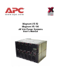
Magnum VS 50
Magnum VS 100
-48 Vdc Power Systems
User’s Manual
Table of Contents
1
Safety First!.............................................................................................................................1
1.1.
WARNING SYMBOLS .........................................................................................................1
1.2.
GENERAL PRECAUTIONS: ..................................................................................................1
2 Introduction .............................................................................................................................2
2.1.
GENERAL INFORMATION ....................................................................................................2
2.2.
HOW TO USE THIS MANUAL ..............................................................................................2
3 Installation ..............................................................................................................................4
3.1.
UNPACKING EQUIPMENT ...................................................................................................4
3.2.
MECHANICAL INSTALLATION ..............................................................................................4
Room / Location......................................................................................................................4
Mounting .................................................................................................................................4
Ventilation ...............................................................................................................................5
3.3.
AC POWER CONNECTIONS ...............................................................................................5
AC Connections......................................................................................................................5
AC Power Cord Sets...............................................................................................................6
3.4.
BATTERY CONNECTIONS ...................................................................................................7
Planning the Battery installation..............................................................................................7
Connecting the Cables ...........................................................................................................7
Battery Temperature Probe Installation ..................................................................................8
3.5.
COUNTER ELECTRO-MOTIVE FORCE (CEMF) CELL CONNECTIONS ......................................9
3.6.
DC SYSTEM GROUNDING ..................................................................................................9
3.7.
LOAD PROTECTION INSTALLATION....................................................................................10
Circuit Breaker Installation ....................................................................................................10
GMT Fuse Installation...........................................................................................................10
3.8.
LOAD CONNECTIONS ......................................................................................................11
Cable Size Considerations ...................................................................................................11
Circuit Breaker Protected Load Connections (30 or 60 A) ....................................................11
GMT Fuse protected Load Connections ...............................................................................11
3.9.
MONITORING AND RELAY OUTPUT CONNECTIONS .............................................................12
Front Panel DB9 Connection ................................................................................................12
RJ45 Ethernet Connector .....................................................................................................12
Major, Minor and Relay 1 Output Connections .....................................................................12
Output Relay 2-6 Connections..............................................................................................13
External Alarm Input Connections ........................................................................................14
3.10. RECTIFIER MODULE INSTALLATION...................................................................................14
3.11. CONTROLLER MODULE INSTALLATION ..............................................................................15
4 Commissioning .....................................................................................................................16
4.1.
PRE-COMMISSIONING INSPECTION ...................................................................................16
Environment..........................................................................................................................16
Electrical Installation .............................................................................................................16
Battery Visual and Safety Inspection ....................................................................................16
4.2.
COMMISSIONING.............................................................................................................17
Initial Set-up..........................................................................................................................17
Magnum VS –48 Vdc User’s Manual
Page ii
AC Power Up ........................................................................................................................17
DC Power Up:.......................................................................................................................17
Rectifier Test:........................................................................................................................18
Battery Power Up..................................................................................................................18
LVD Test...............................................................................................................................18
Circuit Breaker/ Fuse Test: ...................................................................................................18
User Inputs ...........................................................................................................................18
Output Relay 1:.....................................................................................................................19
Battery Temperature Compensation.....................................................................................19
4.3.
FINAL INSPECTION: .........................................................................................................19
5 Technical Description ...........................................................................................................20
5.1.
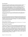
RECTIFIER MANAGEMENT................................................................................................20
AC Input Power.....................................................................................................................20
DC Output Power..................................................................................................................20
Rectifier alarms reporting......................................................................................................20
5.2.
SYSTEM MANAGEMENT ...................................................................................................20
System Voltage Monitor and Control ....................................................................................20
System Current Monitor........................................................................................................21
System Status and Alarm Reporting.....................................................................................21
5.3.
LOAD MANAGEMENT .......................................................................................................21
Circuit Breakers ....................................................................................................................21
GMT Fuses ...........................................................................................................................22
5.4.
BATTERY MANAGEMENT .................................................................................................22
Battery Charging...................................................................................................................22
Battery Equalization..............................................................................................................23
Battery Protection .................................................................................................................23
Battery Temperature Monitoring ...........................................................................................23
Battery Temperature Compensation.....................................................................................23
Battery Low Voltage Disconnect ...........................................................................................24
Battery Functional Test.........................................................................................................24
Counter Electro-Motive Force Module Connections .............................................................24
5.5.
CONTROLS AND INDICATORS ...........................................................................................25
Controller with Display ..........................................................................................................25
Controller without Display .....................................................................................................25
5.6.
ALARM OUTPUTS (OUTPUT RELAYS)................................................................................25
5.7.
EXTERNAL ALARM INPUTS (USER INPUT)..........................................................................26
5.8.
NETWORK MANAGEMENT CARD - LOCAL & REMOTE MONITORING .....................................26
6 Operation ..............................................................................................................................27
6.1.
DESCRIPTION .................................................................................................................27
6.2.
CONTROLLER CARD JUMPERS .........................................................................................27
System voltage J5 ................................................................................................................27
Remote Lockout J8...............................................................................................................27
Firmware Programming Enable J9 .......................................................................................27
Vtrim Trip Select J13 ............................................................................................................27
6.3.
CONTROLLER WITH DISPLAY............................................................................................28
6.4.
OPERATION USING LOCAL DISPLAY AND KEYPAD INTERFACE .............................................29
Magnum VS –48 Vdc User’s Manual
Page iii
6.5.
CONTROLLER WITHOUT DISPLAY......................................................................................36
6.6.
OPERATION USING THE RS-232 COMM PORT ..................................................................36
6.7.
OPERATION USING THE 10/100 BASET ETHERNET PORT ..................................................37
6.8.
OPERATION USING NETWORK MANAGEMENT CARD WEB BROWSER INTERFACE ..................37
6.9.
LVD OPERATION ...........................................................................................................44
6.10. PROGRAMMING OUTPUT RELAYS .....................................................................................45
7 Preventive Maintenance .......................................................................................................47
7.1.
EQUIPMENT ...................................................................................................................47
7.2.
INSPECTION ...................................................................................................................47
Environmental Inspection .....................................................................................................47
System Visual and Safety Inspection....................................................................................47
Battery Visual and Safety Inspection ....................................................................................48
7.3.
TEST .............................................................................................................................48
System Voltage Test.............................................................................................................48
Rectifier Current Share Test .................................................................................................48
System Current Test.............................................................................................................48
Rectifier Alarm Test ..............................................................................................................48
System Temperature Test ....................................................................................................49
Battery Current Test .............................................................................................................49
Battery Temperature Test .....................................................................................................49
LVD Test...............................................................................................................................49
Battery Preventive Maintenance Procedure .........................................................................50
7.4.
FINAL INSPECTION: .........................................................................................................50
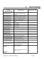
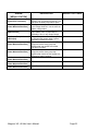
8 Alarm Summary ....................................................................................................................51
9 Specifications........................................................................................................................53
9.1.
AC INPUT ......................................................................................................................53
TWF0500H54B Rectifier .......................................................................................................53
Magnum VS 50 Power System .............................................................................................53
Magnum VS 100 Power System ...........................................................................................54
9.2.
DC OUTPUT ..................................................................................................................54
TWF0500H54B Rectifier .......................................................................................................54
Magnum VS 50 Power System .............................................................................................55
Magnum VS 100 Power System ...........................................................................................55
9.3.
CONTROLS AND INDICATORS ...........................................................................................56
TWF0500H54B Rectifier .......................................................................................................56
Magnum VS Controller .........................................................................................................56
9.4.
MECHANICAL .................................................................................................................56
TWF0500H54B Rectifier .......................................................................................................56
Magnum VS 50 Power System .............................................................................................56
Magnum VS 100 Power System ...........................................................................................57
9.5.
ENVIRONMENTAL ............................................................................................................57
9.6.
COMPLIANCE .................................................................................................................58
10 APC Worldwide Customer Support....................................................................................59
11 Limited Product Warranty ..................................................................................................60
Magnum VS –48 Vdc User’s Manual
Page iv
Revision History
Document # & Rev
990-1479
990-1479A
990-1479B
990-1479C
990-1479D
Date
06 MAY, 2003
03 JUL, 2003
30 SEP, 2003
28 OCT, 2003
06 JAN, 2004
By
BET
BET
BET
BET
BET
Description
Initial Release
Clean-up after Pilot Run
Add Controller with Display
Correct dc connections
Added Output Relays 2-6
Table of Figures
FIGURE 2.1-1 MAGNUM VS 50 –48 VDC POWER PLANT....................................................................2
FIGURE 2.2-1 MAGNUM VS BLOCK DIAGRAM....................................................................................3
FIGURE 3.3-1 MAGNUM VS 50 BACKPLANE ........................................................................................5
FIGURE 3.3-3 AC INPUT WIRING.............................................................................................................6
FIGURE 3.3-5 POWER CORD SETS ..........................................................................................................6
FIGURE 3.4-1 BATTERY CABLE CONNECTION LOCATIONS............................................................8
FIGURE 3.4-3 BATTERY TEMPERATURE PROBE INSTALLATION ..................................................8
FIGURE 3.5-1 CEMF CONNECTION LOCATIONS .................................................................................9
FIGURE 3.7-1 GMT FUSE TEMPERATURE DE-RATING CHART......................................................10
FIGURE 3.7-3 GMT FUSES AVAILABLE FROM APC ..........................................................................10
FIGURE 3.8-1 CONNECTIONS TO CIRCUIT BREAKERS....................................................................11
FIGURE 3.8-2 TOP SHELF GMT FUSE CONNECTIONS ......................................................................12
FIGURE 3.8-3 BOTTOM SHELF GMT FUSE CONNECTIONS .............................................................12
FIGURE 3.9-1 INTERFACE CONNECTIONS..........................................................................................13
FIGURE 3.9-3 OUTPUT RELAY CONNECTIONS..................................................................................14
FIGURE 3.9-5 EXTERNAL USER INPUT CONNECTIONS...................................................................14
FIGURE 6.2-1 CONTROLLER CARD JUMPER LOCATIONS ..............................................................28
FIGURE 6.3-1 CONTROLLER WITH DISPLAY .....................................................................................29
FIGURE 6.4-1 PARAMETER LOCATIONS, DESCRIPTIONS, AND DEFAULT VALUES ................30
FIGURE 6.4-2 MAGNUM VS ENGLISH DISPLAY TREE .....................................................................34
FIGURE 6.4-3 MAGNUM VS CHINESE DISPLAY TREE .....................................................................35
FIGURE 6.5-1 MAGNUM VS CONTROLLER WITHOUT DISPLAY ...................................................36
FIGURE 6.8-1 PARAMETER LOCATIONS, DESCRIPTIONS, AND SETTINGS ................................38
Entire contents copyright © 2003 American Power Conversion. All rights reserved.
Reproduction in whole or in part without permission is prohibited. APC and the APC logo are
trademarks or registered trademarks of American Power Conversion Corporation. All other
trademarks, product names, and corporate names are the property of their respective owners
and are used for informational purposes only.
Magnum VS –48 Vdc User’s Manual
Page v
1
Safety First!
It is very important to follow all safety procedures when unpacking, installing and operating any
sort of power equipment.
1.1. Warning Symbols
CAUTION: An indication that special care is required to prevent injury,
equipment damage or misuse.
WARNING: An indication of an electrical hazard that may cause serious
personal injury or death, catastrophic equipment damage or site destruction.
1.2. General Precautions:
WARNING: Hazardous ac voltage levels are present inside the power
system. Keep the rear cover in place when the system is operational or
energized.
WARNING: Hazardous energy levels are present on bare conductors in the
distribution connection area of the plant. Accidental shorting of distribution
conductors can cause arcing and high currents that can cause serious burns
or other physical harm. It is recommended that:
• Remove any jewelry, rings or watches while working on this equipment.
• Use insulated wrenches, screwdrivers, cutters, pliers and other tools.
WARNING: Ensure that all of the dc and external ac circuit breakers are in
the OFF position prior to connecting service to the power plant. Confirm that
all voltages have been removed including any battery sources before
proceeding.
Specific CAUTION and WARNING will be placed in manual where appropriate.
Magnum VS –48 Vdc User’s Manual
Page 1
2
Introduction
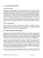
2.1. General Information
DC Power Plants from APC have unique features that make them easy to install, maintain, and
upgrade. The rectifier units are modular and truly “hot-pluggable” into the shelf assembly
without any separate ac wiring. The Magnum VS 50 has 1 shelf, holding up to five rectifiers for
a rated current of 50 A. The Magnum VS 100 has 2 shelves, holding up to ten rectifiers for a
rated current of 100 A. All system settings are made from a standard PC using a serial cable or
a 10/100 Base T connection. The controller provides monitoring and control functions for each
component of the system and stores alarm listings for system diagnosis and maintenance. For
ease of operation, a display with LCD readout and 5-button keypad can be inserted in rectifier
slot 5
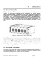
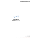
Figure 2.1-1 Magnum VS 50 –48 Vdc Power Plant
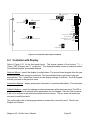
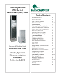
The APC Magnum VS is a modular stand-alone -48 Vdc power plant. It is configurable in such
a manner that it will support most typical applications within the specified current ranges (10-100
A) without special application engineering or assistance. DC output distribution is included for
circuit breakers or GMT style fuses or in the 100-A versions, a combination of both. Available
circuit breakers are 30 A or 60 A. GMT fuses can be 1/4 to15 A. A low voltage disconnect
(LVD) is provided to disconnect the battery after deep discharge. A 50-ampere power system is
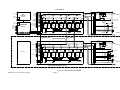
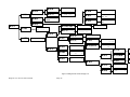
shown in Figure 2.1-1. A block diagram of a typical 100-ampere power system with fuses and
breakers is shown in Figure 2.2-1.
2.2. How to Use This Manual
Each section of this manual can be read in any order and provides a complete explanation of
the subject described by the title. However, the sequence of the sections is designed to provide
a typical step-by-step process for successful use of the equipment.
Magnum VS –48 Vdc User’s Manual
Page 2
TOP SHELF
MAJOR
BATTERY
TEMPERATURE
PROBE
MAJ NC
MAJ C
MAJ NO
MIN NC
MIN C
MIN NO
USER NC
USER C
USER NO
1
TMP
2
-BAT
3
+12 PWR
4
BATTERY
LVD
+PWR
Energized
TX2 Relay
CONTROL BUS
CONTROL BUS
2 Visual Alarms
(1 per group of 4)
DC
AC
DC
AC
DC
AC
DC
AC
DC
AC
Control
DC OK
MINOR
Microprocessor
Control Board
BATTERY (–)
Control
DB-9
PORT
-PWR
Control
ALARM
RELAY
OUTPUTS
1
2
3
4
5
6
7
8
9
BATTERY
SHUNT
Power Distribution Backplane
Control
COMM
PORT
USER
ALARM
INPUTS
WEB
SNMP Card
( AP9617 )
ALM IN_1
ALM IN_2
ALM IN_3
ALM IN_4
ALM RTN
ALM RTN
ALM RTN
ALM RTN
Control
RESET
1
2
3
4
5
6
7
8
( 0P1838 )
OUT RLY
8 outputs: Rear
CONTROL BUS
GND
GND
L1 L2/N
GND
L1 L2/N
GND
TRM15
( 0P1839 )
L1 L2/N
Signals Cable
GMT Load Distribution Module
( 0P1849 )
BATTERY (+)
Bus Bars
BOTTOM SHELF
BATTERY
LVD
+PWR
Energized
TX2 Relay
CONTROL BUS
CONTROL BUS
DC
AC
DC
AC
DC
AC
DC
AC
DC
AC
Control
Visual Alarm
Control
1
2
3
4
BATTERY (–)
Control
COVERED
Blank Panel
-PWR
Control
COVERED
1
2
3
4
5
6
7
8
9
BATTERY
SHUNT
Power Distribution Backplane
Control
COVERED
1
2
3
4
5
6
7
8
Stud outputs:
Rear
GND
GND
GND
GND
TRM15
Visual Alarm
L1 L2/N
L1 L2/N
L1 L2/N
( 0P1839 )
100 Amp System Only
Figure 2.2-1 Magnum VS BLOCK DIAGRAM
Magnum VS –48 Vdc User’s Manual
Page 3
2 CB Load Distribution Module ( 0P1852 )
BATTERY (+)
3
Installation
3.1. Unpacking Equipment
Remove equipment from packing material and inspect for shipping damage or missing items. It
is important to report damage or material shortages to the shipping carrier while a
representative is on site.
If concealed damage or material shortages are found at a later time, contact the shipper to
make arrangements for inspection and claim filing. Refer to Section 10 in the event it is
necessary to return equipment to APC.
CAUTION: Appropriate lifting techniques and safety equipment should be
used to remove equipment from packing.
PLEASE RECYCLE: The shipping materials can be recycled. Please save
them for later use or dispose accordingly.
3.2. Mechanical Installation
Room / Location
NOTE: The APC dc power plant is to be installed in a room, vault, or similar enclosure that is
accessible only to qualified persons in accordance with the regulatory authority having
jurisdiction.
Prior to installation, drawings, floor loading requirements, external alarm points, ac service
entrance, and grounding schemes should all be checked and confirmed. If batteries are to be
mounted in a room separate from the power plant, careful attention should be paid to battery
cable voltage drop effects. Environmental operating temperatures and ventilation/cooling
considerations should also be noted, not just for the power system but also for all other
equipment that may reside in the power room area.
Mounting
The Magnum VS provides brackets to mount on a standard EIA 19 or 23-inch rack. Install the
power system using hardware designed for the rack. To install a Magnum VS 50 on a 23-inch
rack use bracket kit number 0M-2829. To install a Magnum VS 100 on a 23-inch rack use
bracket kit number 0M-2830.
Magnum VS –48 Vdc User’s Manual
Page 4
Ventilation
The rectifier modules for this system have fans that provide front-to-rear airflow for internal
cooling. The power system housing should be mounted such that there is free airflow to the
front and back of the unit. [Refer to Section 9.5 for environmental characteristics.] Free airflow
should be ensured so that the power system can provide full power without de-rating.
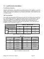
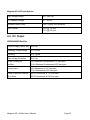
3.3. AC Power Connections
WARNING: Ensure that all of the external dc and ac circuit breakers are in the
OFF position prior to connecting service to the power plant. Confirm that all
voltages have been removed including any battery sources before proceeding.
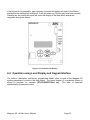
AC Connections
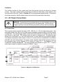
The dc power system requires the supply of 85 – 264 Vac, 47 – 63 Hz single phase power. One
alternating current (ac) input on the power system backplane supplies power to the first rectifier
in each shelf. Two inputs supply power to the second and third pair of rectifiers and the fourth
and fifth pair in each shelf. This scheme allows a variety of wiring options. Provided the input
wiring is not overloaded, one, two or all three inputs on each shelf can be jumpered together.
The ambient temperature and number of wires in a conduit must be considered in accordance
with NEC and local requirements. The power system typically ships with the jumpers shown in
the backplane layout of the Magnum VS 50 shown in Figure 3.3-1. The Magnum VS 100
contains two identical backplanes. The input terminals are defined in Figure 3.3-3. If one ac
input cable is used it is typically connected to TRM10, 7 and 4.
Figure 3.3-1 Magnum VS 50 Backplane
Magnum VS –48 Vdc User’s Manual
Page 5
Rectifier
Terminal # Function
Rectifier 1
TRM2
Ground
Rectifier 2 & 3
TRM3
Ground
Rectifier 4 & 5
TRM4
Ground
Chassis
TRM1
Ground
Terminal #
TRM5
TRM6
TRM7
Function
Line or Neutral
Line or Neutral
Line or Neutral
Terminal #
TRM8
TRM9
TRM10
Function
Line
Line
Line
Figure 3.3-3 AC Input Wiring
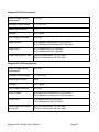
AC Power Cord Sets
AC input cable kits are available from APC. These cables are 12 feet (3.7m) long and have a
power plug installed on each cable. When ordered with the power system, these cables will be
installed with strain reliefs provided to mount the 3-conductor jacketed cables. Each kit will
supply power to the entire power system. Use the chart in Figure 3.3-5 to determine the
suggested cable kits.
Part Num.
0M-91157
0M-91155
0M-91156
0M-91154
0M-91158
0M-1150
0M-91160
0M-91159
0M-91137
0M-91140
0M-91138
0M-91141
0M-91139
0M-1149
0M-91135
0M-91136
AWG
14
14
12
12
10
12
10
10
12
12
12
12
10
12
10
10
Cable Qty
3
3
2
2
1
2
1
1
6
6
4
4
2
4
2
2
Plug Num.
NEMA 5-15
NEMA L5-15
NEMA 5-20P
NEMA L5-20P
NEMA 5-50P
NEMA L6-20P
NEMA 6-30P
NEMA L6-30P
NEMA 5-15P
NEMA L5-15P
NEMA 5-20P
NEMA L5-20P
NEMA 5-50P
NEMA L6-20P
NEMA 6-30P
NEMA L6-30P
Plug Style
Non-locking
Locking
Non-locking
Locking
Non-locking
Locking
Non-locking
Locking
Non-Locking
Locking
Non-locking
Locking
Non-locking
Locking
Non-locking
Locking
Voltage Power System
115
Magnum VS 50
115
Magnum VS 50
115
Magnum VS 50
115
Magnum VS 50
115
Magnum VS 50
230
Magnum VS 50
230
Magnum VS 50
230
Magnum VS 50
115
Magnum VS 100
115
Magnum VS 100
115
Magnum VS 100
115
Magnum VS 100
115
Magnum VS 100
230
Magnum VS 100
230
Magnum VS 100
230
Magnum VS 100
Figure 3.3-5 Power Cord Sets
WARNING: Hazardous ac voltage levels are present inside the power
system. Keep the rear cover in place when the system is operational or
energized.
The rear cover of each shelf in the power system is provided with two 1.125-inch (2.858 cm)
diameter holes for electrical conduit. Conduit can be run to each shelf or strain reliefs are
provided to install jacketed cables.
Magnum VS –48 Vdc User’s Manual
Page 6
3.4. Battery Connections
WARNING: Hazardous energy levels are present on bare conductors in the
dc distribution connection area of the plant.
Accidental shorting of
distribution conductors can cause arcing and high currents that can cause
serious burns or other physical harm. It is recommended that:
• Remove any jewelry, rings or watches while working on this
equipment.
• Use insulated wrenches, screwdrivers, cutters, pliers and other tools.
Planning the Battery installation
The battery cable(s) should be sized to limit the voltage drop from the dc power plant to the
battery during charging per system design requirements. The cable(s) must also carry the full
load current during battery operation. If assistance is required to determine the necessary
cables for the application, contact your sales representative or APC (Refer to Section 10 for
APC Customer Support information. A fuse or circuit breaker (various options are available
from APC) is recommended in the negative line to protect the cables from the battery to the dc
power plant. If a circuit breaker is used, the power plant can monitor auxiliary contacts from this
breaker.
Connecting the Cables
WARNING: Make certain that the battery polarity is correct when making
connections to the dc power plant. Incorrect connection could cause severe
equipment damage.
The battery cable connections are located at the rear of the unit as shown in Figure 3.4-1. The
battery positive and battery negative buses each provide a pair of #10-32 studs on 5/8” centers
for connecting two-hole battery cable lugs. A ring size of 6 mm may also be used. Connect the
battery cables as applicable using #10-32 nuts. Cover connections with heat shrink after
assembly.
Magnum VS –48 Vdc User’s Manual
Page 7
Battery Negative
Connection
Battery Return
Connection
Figure 3.4-1 Battery Cable Connection Locations
Battery Temperature Probe Installation
The temperature probe is used to monitor the battery string temperature. To get the most
representative temperature measurement, the probe should be placed in contact with a battery
cell that is centrally located. The probe should be placed directly in contact with the cell (not the
frame surrounding the cell). Generally, the cell cover can be used; be careful not to allow the
probe body to touch the terminals. Plug the connector end of the temperature probe into J410
of the backplane card. Route the cable as required positioning the probe on the selected
battery cell. Remove the adhesive protection strip from the probe body and press the adhesive
side of the probe on the battery cell cover. Refer to Figure 3.4-3 for details.
Note: Program Hardware battery temperature alarm to Ignore if no battery temperature
probe is connected to J410.
Battery
Temperature
Probe
Connector
J410 (Rear
Cover
Removed)
Figure 3.4-3 Battery Temperature Probe Installation
Magnum VS –48 Vdc User’s Manual
Page 8
3.5. Counter Electro-Motive Force (CEMF) Cell Connections
WARNING: Hazardous energy levels are present on the CEMF connection
area of the plant. Accidental shorting of conductors can cause arcing and
high currents that can cause serious burns or other physical harm.
In some applications, a CEMF cell is used to lower the dc voltage delivered to the loads. The
CEMF cell is mounted externally to the Magnum VS. The CEMF connections are located at the
rear of the unit as shown in Figure 3.5-1. Two bus-plates, installed at the factory, bypass the
CEMF connection. If a CEMF cell will be used, remove the bus plate connecting the two CEMF
connection points and install two connection buses before installing the CEMF. The CEMF
connection buses each provide a pair of #10-32 studs on 5/8” centers for connecting two-hole
CEMF cable lugs. A ring size of 6 mm may also be used. Connect the CEMF cables as
applicable using #10-32 nuts.
CEMF Connections
Figure 3.5-1 CEMF Connection Locations
3.6. DC System Grounding
The positive bus for the power plant should be connected to the Central Office Ground. The
Battery Return provide a pair of #10-32 studs on 5/8-inch centers for connection of a two-hole
lugged cable to the Central Office Ground. A ring size of 6 mm may also be used. Cover this
connection with heat shrink tubing after assembly.
Magnum VS –48 Vdc User’s Manual
Page 9
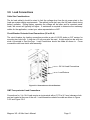
3.7. Load Protection Installation
Circuit Breaker Installation
Standard circuit breaker output boards are available with two 30-A breakers or one 60-A
breaker. Output boards are installed at the factory and are generally not field replaceable units.
Contact APC if the output configuration is not suitable for your needs. Other breaker sizes are
not readily available.
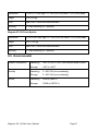
GMT Fuse Installation
Fuse holders that accommodate GMT fuses are located on the front panel on the left side of the
unit. Insert the fuse in the holder; observing the tripped indicator is correctly oriented. Use the
chart shown in Figure 3.7-1 to help determine what size fuses will carry the desired current.
When using several of the larger GMT fuses in one shelf, better heat dissipation will be
achieved if the fuses are spaced out evenly within the output panel. A list of GMT type fuses
available from APC is provided in Figure 3.7-3.
FUSE
SIZE
AMBIENT TEMPERATURE
20° C
50° C
60° C
7.5 A
5A
4.5 A
4A
10 A
7A
6A
5A
15 A
10 A
9A
8A
Figure 3.7-1 GMT Fuse Temperature De-rating Chart
GMT Fuses
FUSE RATING
PART NUMBER
FUSE RATING
PART NUMBER
¼A
FFA-0030
3A
FFA-0036
½A
FFA-0031
5A
FFA-0037
3/4 A
FFA-0032
7½ A
FFA-0029
1A
FFA-0033
10 A
FFA-0038
1¼ A
FFA-0039
15 A
FFA-0040
1½ A
FFA-0035
Figure 3.7-3 GMT fuses available from APC
Magnum VS –48 Vdc User’s Manual
Page 10
3.8. Load Connections
Cable Size Considerations
The dc load cable(s) should be sized to limit the voltage drop from the dc power plant to the
loads per system design requirements. The cable(s) must also carry the full load current during
battery operation. During battery operation the voltage will be lower and for constant power
loads, the current will typically be higher. If assistance is required to determine the necessary
cables for the application, contact your sales representative or APC.
Circuit Breaker Protected Load Connections (30 or 60 A)
The circuit breaker lug landing connection provides a pair of #10-32 studs on 5/8” centers for
mounting two-hole lugs. A ring size of 6 mm may also be used. A right angle bus bar with two
studs is provided to land the lugs. Load Connections should be made as shown in. Cover
connections with heat shrink after assembly.
-54 Volt Load Connections
Load Returns
Figure 3.8-1 Connections to Circuit Breakers
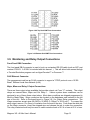
GMT Fuse protected Load Connections
Connections for ¼ to 14-A loads require a ring terminal with a 0.170 in (4.3 mm) clearance hole
and are located at the rear of the unit. Load connections should be made as shown in Figure
3.8-2 and Figure 3.8-3
Magnum VS –48 Vdc User’s Manual
Page 11
Figure 3.8-2 Top Shelf GMT Fuse Connections
Figure 3.8-3 Bottom Shelf GMT Fuse Connections
3.9. Monitoring and Relay Output Connections
Front Panel DB9 Connection
The front panel DB-9 connector is used to hook up a standard RS-232 cable (such as APC part
number 0129-XX. A 0129-6 is included with this manual. ). This will allow local access through
a Terminal Emulation program such as HyperTerminal™ or Procomm.™
RJ45 Ethernet Connector
The management card has an RJ-45 connector to support a TCP/IP protocol over a 10/100
BaseT Ethernet Local Area Network (LAN).
Major, Minor and Relay 1 Output Connections
There are three output relays available that provide outputs via Form “C” contacts. The output
relays are named Minor, Major and Out Relay 1. Various system alarm conditions can be
assigned to any of these three output relays. Most alarm conditions are shipped programmed to
Minor or Major Relay. Wago connectors are located on the backplane card mounted in the left
rear of the unit. Refer to the board layout in Figure 3.9-1 for Output Relay connections. The
Wago connectors accept wires 26 AWG to 20 AWG (0.129mm2 to 0.518 mm2). To connect the
relay output, remove ¼ in (6mm) of insulation from the end of the wire. Push down the white tab
on the Wago connector, insert the stripped wire and release the tab to make the connection.
The relay contacts should only be used to switch resistive loads of 0.5 A or less at 60 V or less.
Magnum VS –48 Vdc User’s Manual
Page 12
Figure 3.9-3 shows the alarm output connection designations. Whenever possible use the
common and normally closed contacts. If the alarm wiring gets pulled loose, or the controller is
removed, you will get an alarm. The Major relay is energized (C-NO contacts closed) during
normal (non-alarm) operating conditions; the other relays energize when an alarm condition
occurs. If your Major relay wiring uses the C-NO contacts, then a major relay output will be
seen whenever the controller is removed from the shelf.
Output Relays
(J411)
User Inputs
(J412)
Figure 3.9-1 Interface Connections
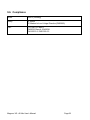
Output Relay 2-6 Connections
Output Relays 2 through 6 are virtual relays and are not available for physical connection by the
user. The small size of this unit limits the number of relays that can be placed in the system.
These output relays are supported by the controller and reported by the network management
card. Any alarm condition can be programmed to map to one of these relays. The alarm will
activate the relay, illuminate the front panel Out Relay LED, and send the relay output message
to the network management card.
RELAY
OUTPUT
OUT RELAY #1
OUT RELAY #2
OUT RELAY #3
OUT RELAY #4
OUT RELAY #5
J 411 TERMINAL
DESIGNATIONS
NO
C
NC
N/A
N/A
N/A
N/A
Magnum VS –48 Vdc User’s Manual
RELAY ALIAS
OUTPUT RELAY NOTES
Page 13
OUT RELAY #6
MINOR
MAJOR
N/A
NO
C
NC
NO
C
NC
N/A
N/A
N/A
N/A
N/A
N/A
Figure 3.9-3 Output Relay Connections
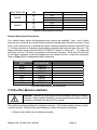
External Alarm Input Connections
Four external alarm inputs with assignable relay outputs are available. User 1 and 2 inputs
respond only to external dry contact closures between normally open (NO) and common (C) and
User 3 and 4 respond only to external dry contact openings between normally closed (NC) and
C. A Wago connector is located on the backplane card mounted in the left rear of the unit. The
Wago connectors accept wires 26 AWG to 20 AWG (0.129mm2 to 0.518 mm2). To connect the
user input, remove ¼ in (6mm) of insulation from the end of the wire. Push down the white tab
on the Wago connector, insert the stripped wire and release the tab to make the connection.
Refer to Figure 3.9-1 for backplane board connections.
EXTERNAL ALARM
INPUT
#1 NO
#2 NO
#3 NC
#4 NC
#1 C
#2 C
#3 C
#4 C
J412 TERMINAL
DESIGNATIONS
USER1NO
USER2NO
USER3NC
USER4NC
USER1C
USER2C
USER3C
USER4C
USER ALARM NOTES
Figure 3.9-5 External User Input Connections
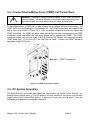
3.10.Rectifier Module Installation
WARNING: Rectifier dc output circuits will be damaged if battery is installed
incorrectly. Before rectifier installation, ensure proper battery polarity and that
the battery is isolated from the rest of the system
The rectifier modules are shipped in separate containers. Follow the procedure below to install
a rectifier module. Rectifiers may be installed even when the system is energized.
1) Remove the rectifier from its shipping container.
Magnum VS –48 Vdc User’s Manual
Page 14
2) Slide the rectifier module into the shelf between the guides until it is fully seated.
3) Fasten the rectifier in place with the captive rectifier retaining screws.
Since all adjustments are made from the system controller, no rectifier adjustments are
necessary.
3.11. Controller Module Installation
CAUTION: The controller and the network management card have lithium
batteries. These batteries are not field serviceable.
• Danger of explosion if battery is replaced by an incorrect type.
• Dispose of used batteries according to the manufacturer’s instructions.
The controller is installed in the Magnum VS 50 in the right hand side of the power system. The
controller is installed in the Magnum VS 100 in the upper right hand side of the power system.
Insert the card taking care to follow the alignment guides all the way to the rear of the unit. The
connector on the rear will hot plug into the power system backplane.
To install the controller with display, first remove rectifier number 5, which is in the slot nearest
the controller. Insert the card taking care to follow the alignment guides all the way to the rear of
the unit. The connector on the rear will hot plug into the power system backplane. Removing
the rectifier will decrease the total output capacity of the power system.
Magnum VS –48 Vdc User’s Manual
Page 15
4
Commissioning
This section is intended as a guide when powering up a system for the first time. It may not be
desirable to perform some steps depending on the particular installation. Refer to the
appropriate section for information relating to how these steps should be performed.
4.1. Pre-Commissioning Inspection
Environment
1.
2.
3.
4.
Ensure the dc system environment is suitable for operation.
Ensure that there is sufficient clearance around the system for service.
Ensure that there is no sign of damage to the dc system.
Disable installed alarms before servicing the unit. This will allow the unit to be serviced
without creating false alarms.
Electrical Installation
1.
2.
3.
4.
Ensure that the dc wiring is properly installed, sized, terminated and identified.
Ensure that the ac wiring is properly installed, sized, terminated and identified.
Ensure that the battery wiring is properly installed.
Ensure that the dc output over-current protection devices are adequate for the size of
wiring installed.
5. Ensure that the dc positive is bonded to central office ground.
6. Note the resistance of the ground bond.
7. Note any currents flowing in the ground.
8. Record ambient temperature.
9. Verify that the battery polarity is correct.
10. If a battery disconnect device(s) is/are present, note the following for each device:
a. DC voltage Rating.
b. DC Current Rating
c. Interrupting Current Rating
Battery Visual and Safety Inspection
1.
2.
3.
4.
5.
6.
Check the mechanical integrity of the battery framing, racking, or cabinet.
Check that the battery framing, racking or cabinet is adequately secured to the floor.
Check compliance with seismic zone requirements.
Check the general appearance and cleanliness of the battery.
Record the manufacturer, model number, and capacity of the battery string(s).
Record the batch number, date code, and serial number of each cell or mono-block, and
any other pertinent information that is available on the battery cells.
7. Check that the cell or mono-block numbering starts at the positive battery string terminal
and is correct.
Magnum VS –48 Vdc User’s Manual
Page 16
8. Check that anti-oxidation compound is properly applied.
9. Visually inspect each cell for:
a. Cracks.
b. Case leaks.
c. Post-seal leaks.
d. Pressure relief valve leaks (VRLA only).
e. Case swelling (VRLA only).
10. Check the torque of all battery inter- cell connector in accordance with the battery
manufacturer’s specifications.
4.2. Commissioning
Initial Set-up
1.
2.
3.
4.
Remove all rectifiers.
Disconnect battery by removing a link in each string or opening the battery disconnects.
Check that battery voltage does not appear on the system bus.
Disconnect all loads.
AC Power Up
WARNING: The dc power plant is supplied from a nominal high voltage ac
voltage source. Keep the ac input enclosure cover in place when the system
is operational or energized
1. Verify that all of the circuit breaker positions are labeled to the corresponding rectifier
correctly.
2. Insert all rectifiers.
3. Turn all rectifier circuit breakers on.
4. Each rectifier should have green Input Healthy and Output Healthy LEDs illuminated.
NOTE: When ac power is initially applied, there is a 60-second period during which no alarms
are reported.
DC Power Up:
1.
2.
3.
4.
5.
6.
Verify with a voltmeter that the dc voltage is within 0.1 Vdc of the System Voltage
Adjust battery float voltage to negative 49 Vdc.
Verify System Low Voltage Alarm.
Adjust battery float voltage to negative 57 Vdc.
Verify System High Voltage Alarm.
Restore the battery float voltage to negative 54.00 Vdc or desired voltage.
Magnum VS –48 Vdc User’s Manual
Page 17
Rectifier Test:
1. To verify that all rectifiers are reporting correctly to the controller, navigate through the
menu and verify that the status for every rectifier in the system is correct.
2. Remove any rectifier and verify that you get a Minor Relay Output for rectifier 1 of n
failure.
3. Remove a second rectifier and verify that you get a Major Relay Output for rectifier 2 of n
failure.
Battery Power Up
1. Monitor battery current and verify that it is +/- 0.1 A.
2. Set battery maximum recharge value in the Max Batt Rech screen.
3. Monitor the battery current while closing the battery disconnects or installing open battery
links. Arcing can occur during this connection.
4. The voltage may drop if the maximum battery recharge current is exceeded.
5. The current should gradually decrease when the battery is nearing full charge.
LVD Test
1. Enable LVD 1.
2. Set the LVD trip for LVD 1 to negative 56 Vdc.
3. The LVD should have dropped out (opened). Verify by monitoring the voltage at the
battery connection. Also, the minor alarm should be on.
4. Set LVD Trip back to negative 42 Vdc.
5. The LVD should have closed. Verify visually or by monitoring the voltage at the battery
connection. The minor alarm should be off.
6. Ensure that the LVD parameters are set to desired value.
Circuit Breaker/ Fuse Test:
1. Monitor alarm screen for fuse alarm while installing blown GMT fuses in each position.
2. Verify proper voltage at fuse and circuit breaker output connections.
3. Turn on fuses and circuit breakers as desired.
User Inputs
1. Change the user input to desired output relay via the controller for any input that will be
used.
2. Exercise the output relay by causing the user input to change state.
3. Verify the desired relay output LED on the controller module.
Magnum VS –48 Vdc User’s Manual
Page 18
Output Relay 1:
1. Minor and Major output relays were tested in the rectifier test section.
2. Change the alarm to desired relay output via the controller for any relay output that will be
used. All alarm parameters are shipped as either major or minor, but may be changed to
output relay 1.
3. Program output relay 1 to desired major or minor alarm to complete programming.
4. Exercise the output relay by causing the alarm to change state.
Battery Temperature Compensation
1. Enable battery temperature compensation if desired.
2. Ensure that battery temperature probe is connected to the system and attached to the
battery.
3. Verify that the system voltage is above the float voltage setting if the battery temperature
is below 25 degrees C and below the float voltage setting if the battery temperature is
above 25 degrees C.
4.3. Final Inspection:
1. Verify that the interior and exterior of the system is clean and free from debris.
2. Ensure all wires connected and bolts are properly tightened.
3. Ensure the following the User, Service, and Calibration parameters are set properly on
the controller:
LVD
LVD1 Trip
LVD1 Reset
Battery Parameters
Discharge Threshold
Float Voltage
Maximum Recharge
Compensation Method
4. Verify that the system is functioning correctly with no alarms.
Be sure to leave the site as orderly and neat as possible.
Magnum VS –48 Vdc User’s Manual
Page 19
5
Technical Description
The Power System is designed to supply safe –54 Vdc primary power through the use of up to
10 rectifier modules. The controller will monitor all functions and provides battery management
including controlled battery recharge with temperature compensation and low voltage
disconnect. Integrated dc output distribution supports loads ranging from ¼ A all the way to 60
A. The controller can monitor up to 4 discrete external events with voltage free (“dry contact”)
user inputs.
5.1. Rectifier Management
AC Input Power
The basic component of the power system is the rectifier module, which rectifies utility ac into
nominal 48 Vdc. Each rectifier module requires 85 – 264 Vac, 47 – 63 Hz single phase power.
Available cord sets include a variety of blade and twist lock plugs. Dedicated wiring inside
conduit can also be used.
DC Output Power
The dc outputs of all the rectifiers in the system are connected to a common bus that is rated to
carry the current of the entire system. The rectifier modules will equally share the entire load,
independent of the controller. The rectifiers will continue to provide dc power (-54.5Vdc) if the
controller is removed or fails.
Rectifier alarms reporting
The rectifier has numerous sensors inside the unit that monitor fan fail, high temperature,
high/low voltage, etc. These rectifier sensors trigger outputs that are monitored by the
controller. In addition rectifier current is measured inside each rectifier. The controller can
trigger output relays in the event of a rectifier alarm. Refer to Section 5.5 for controller functions.
5.2. System Management
System Voltage Monitor and Control
The controller monitors and adjusts the system voltage. It uses a voltage trim input to the
rectifier to precisely control the dc output voltage. In the event of controller removal or failure,
individual rectifiers will default to the analog voltage level (-54.5 Vdc) preset at the factory.
System high and low voltage alarms are reported by the controller.
Magnum VS –48 Vdc User’s Manual
Page 20
System Current Monitor
The controller monitors individual rectifier currents and displays total system current as a sum of
rectifier currents. Load current can be found by adding battery current to system current.
Battery Current is positive when the battery is discharging.
Sys Current + Batt current = Load Current
For example, if the battery is charging the Batt Current reading could be (–) 10 A, Sys Current
reading could be 50 A. Load Current would be:
Sys Current + Batt current = Load Current
50 A + (-) 10 A = 40 A.
If the battery is discharging the Batt Current reading could be 10 A, Sys Current reading could
be 30 A. Load current would be:
Sys Current + Batt current = Load Current
30 A + 10 A = 40 A.
System Status and Alarm Reporting
The controller will monitor system, temperature. The controller reports system high and low
temperature alarms.
5.3. Load Management
Circuit Breakers
Distribution is included for up to 2 circuit breakers or eight GMT fuses per 50-A shelf. The circuit
breakers can be 2 X 30 A or 1 X 60 A in each shelf. The GMT fuses are 8 X ¼ to 15 A in each
shelf. When a circuit breaker trips, a normally open switch closes and the controller reports a
CB alarm. Alarms are reported only when a breaker is tripped. When a breaker is turned off, no
alarm is generated. Circuit Breaker Alm 1 or 2 are reported when a circuit breaker in the top
shelf trips. Circuit Breaker Alm 3 or 4 are reported when a circuit breaker in the bottom shelf
trips. Because of this, if a Magnum VS 100 has GMT fuses in the top shelf and 2 circuit
breakers in the bottom shelf, the circuit breakers will be labeled CB1 & CB2 on the front panel,
but Circuit Breaker Alarm 3 & 4 will be reported. If a Magnum VS 100 has GMT fuses in the top
shelf and 1 circuit breaker in the bottom shelf, the circuit breaker will be labeled CB1 on the front
panel, Circuit Breaker Alarm 3 will be reported. If a Magnum VS 100 has 1 circuit breaker in the
top shelf and 1 circuit breaker in the bottom shelf, the circuit breakers in the bottom shelf will be
labeled CB2 on the front panel, but Circuit Breaker Alarm 3 will be reported. To disconnect a
load attached to a circuit breaker, move the lever down to the “OFF” position.
Magnum VS –48 Vdc User’s Manual
Page 21
GMT Fuses
When a GMT fuse trips, a fuse element burns out allowing the indicator to connect dc power to
the alarm contact. This turns on the fuse alarm LED on the fuse panel indicating the affected
group and the controller reports a fuse alarm. Each controller fuse alarm combines alarms from
4 individual fuses:
Fuse F1 to F4 : Fuse Alarm 1.
Fuse F9 to F12 : Fuse Alarm 3.
Fuse F5 to F8 : Fuse Alarm 2.
Fuse F13 to F16 : Fuse Alarm 4.
To disconnect a load attached to a GMT fuse pull the fuse straight out of the fuse holder base.
5.4. Battery Management
Battery Charging
Battery charging is integrated into the dc power system to support the primary function of
providing power to the load. Accurate measurement of battery parameters such as voltage,
current and temperature are used to maintain and protect the batteries attached to the power
plant.
Charging the battery at the correct rate reduces battery heating, increases the charge returned
to the battery and prevents excess hydrogen generation or, in the case of Valve Regulated Lead
Acid (VRLA) batteries, possible thermal runaway. The Magnum VS operates as a current
limited constant voltage battery charger. The current limit value is set by the controller’s Battery
Maximum Recharge Current parameter and is normally based on the size of the battery plant in
ampere-hours.
Consult the battery manufacturer for the recommended maximum charging current. This is
frequently expressed as a percentage of the battery's 20-hour ampere-hour capacity rating,
commonly abbreviated as "C". For example, the maximum recharge current in amperes may be
expressed as 0.2C, 20% C or C/5, all of which are equivalent. If the battery used has a capacity
of 120 Ah, then the 0.2 C max current is 24 amperes. Manufacturers typically specify max
recharge current between 0.1C to 0.3C (C/10 to C/3). Avoid high recharge rates that may induce
elevated battery temperatures that can lead to thermal runaway. A 0.1C max recharge current
is generally a conservative value that will result in a 90-95% recharge in 12-15 hours, depending
on the initial depth of discharge. In this case charging current will begin to taper (reduce) from
the current limited value after 3.5 - 7 hours.
Typically four 12-volt batteries are connected in series to form a battery string. The ampere-hour
rating for one 12-volt battery will equal the Ah rating of the string. For multiple parallel strings,
add the Ah rating of each string together to get the total Ah rating.
Magnum VS –48 Vdc User’s Manual
Page 22
Battery Equalization
Battery equalization equalizes the specific gravity of the electrolyte in the cells of a battery. It is
accomplished by applying a controlled overcharge to the battery. Equalization may be
appropriate (1) after a battery has been in float charge for extended periods time, (2) after a
battery has been significantly discharged, or (3) at the time of initial battery installation. There
are three methods by which the Magnum VS controller may initiate equalization: manual,
periodic and automatic. Manual Equalization is a one time equalization initiated by the user.
Periodic Equalization occurs after a set number of days. Automatic Equalization occurs after a
set time period of ac power failure or a set percentage of battery ampere-hour discharge. The
factory default for all equalization methods is OFF. Refer to the Equalization setup parameters
in the table of Section 6.4. The maximum equalization voltage is limited to the system maximum
voltage adjustment of -56.5 Vdc.
Presently, the equalization function is only accessible through the controller display keypad. A
future upgrade to the network management card is planned that will allow equalization to be
accessible remotely.
Battery Protection
An external disconnect should be mounted at the battery string to protect the system from the
high energy stored in the battery if a short occurs. The battery LVD will not be energized until a
battery string is installed with the proper polarity and the battery disconnect switch is turned on.
The battery connections are to be used for the battery only. Do not attach loads to the battery
connections or erroneous battery current will be reported. The controller reports Battery high
and low voltage alarms and LVD alarms.
Battery Temperature Monitoring
Battery temperature is monitored using a probe attached to the battery casing. The controller
reports Battery high and low temperature alarms.
Battery Temperature Compensation
The Battery Float Voltage is set to the value recommended by the battery manufacturer in order
to maintain correct battery charge at 25ºC. As temperature rises, electrochemical activity in a
battery increases. Similarly, as temperature falls, electrochemical activity in a battery
decreases. As temperature rises, charging voltage should be reduced to prevent overcharge
and possible thermal runaway. As battery temperature falls, voltage is increased to prevent
undercharge. The dc power system uses Battery Temperature compensation to change output
voltage to compensate for temperature changes monitored at the battery temperature probe.
This temperature compensation function is programmed into the controller using the
compensation parameters settings. Default settings can be changed to values recommended
by the particular battery manufacturer. The controller will not allow the system voltage to be
adjusted beyond the range of –47 Vdc to –56.5 Vdc.
Magnum VS –48 Vdc User’s Manual
Page 23
Battery Low Voltage Disconnect
In order to prevent damage to the battery due to deep discharge, the dc power system has
hardware and software support for a battery Low Voltage Disconnect (LVD). When the battery
voltage reaches the threshold set by the LVD 1 Trip Voltage setting during discharge, the dc
power system will activate the LVD contactor to disconnect the battery from the system. The
LVD will remain open until ac power is restored to the system and the bus voltage reaches the
level defined by the LVD 1 Reset Voltage variable. The LVD control can be disabled on the
LVD parameters screen in the controller.
NOTE: The LVD is normally energized and must be commanded to open. This assures that
the LVD will remain closed even if the controller fails or is removed.
The LVD will not be energized until a battery string is installed with the correct polarity and the
battery disconnect switch is turned on. This will prevent the battery from being hooked up
backwards and damaging the rectifiers and/or the loads. Once the battery is connected
correctly and the LVD is closed, the LVD will open only in low voltage situations. The battery
connections are to be used for the battery only.
Battery Functional Test
The controller is able to functionally test the battery. This is a short duration test intended to
confirm that the battery can deliver current to the load without an unusual drop in system
voltage. Excessive voltage drop may be an indication of high resistance electrical connections,
high battery internal impedance or impending battery failure. For the test the controller lowers
the system voltage sufficiently that the batteries will deliver the current required by the load
equipment and thereby start to discharge. The controller monitors the voltage drop to determine
if the battery is good or bad. A collapse of voltage will not cause an interruption in power to the
load, as the rectifiers remain operational and will continue to support the load if this occurs.
Functional test defaults are a 10 second duration and -48 V pass/fail voltage threshold. Very
high or low equipment loads relative to the size of the battery may invalidate the results of this
test. Presently this test may only be initiated manually via the controller with display keypad. A
future upgrade will add this capability to the network management card for remote access.
Counter Electro-Motive Force Module Connections
A connection is provided to connect a Counter Electro-Motive Force (CEMF) Module. A CEMF
is a semiconductor device connected in series with a battery and used to reduce the voltage to
loads that cannot tolerate the “normal” main cell voltage. The CEMF cells are automatically
switched out of the circuit when the discharge voltage drops to a predetermined level and are
automatically switched back into the circuit when the battery approaches its normal float value.
Magnum VS –48 Vdc User’s Manual
Page 24
5.5. Controls and Indicators
Controller with Display
The Magnum VS may be equipped with an optional advanced controller. This controller has an
LCD display and a 5-button keypad. This controller uses the normal control card slot as well as
the adjacent slot for rectifier 5. Most common parameter monitoring and programming can be
made right at the power system using this interface. Any other changes must be made either
locally using a PC or remotely by interface to the network management card. Refer to Section 6
for further information. There are five LEDs visible on the control card. The Major LED (Red) is
on when the Major Relay is de-energized. The Major Relay is energized when there is no
alarm. This will produce a major relay output even when all power is lost. The Minor LED
(Yellow) is on when the Minor Relay is energized. The Out Relay LED (Yellow) is on when the
Out Relay is energized. The DC OK LED (Green) is on when the voltage is between 50 and 57
Vdc. The green LED behind the front panel is slowly flashing when the controller is processing
data.
Controller without Display
There are no switches or controls of any kind on this controller. All parameter changes or
viewing of status is made either locally using a PC or remotely by interface to the network
management card. Refer to Section 6 for further information. LED indicators and relay
operation is identical to that found on the controller with display.
5.6. Alarm Outputs (Output Relays)
There are three alarm output relays designated Out Relay 1, Minor, and Major. Various system
parameters may be programmed to activate any of these output relays when set thresholds are
exceeded or specific conditions occur. Out Relay 1 can also be routed or “mapped” to “Out
Relay 1-6,” “Minor Relay,” “Major Relay” or “Ignore.” This feature makes it possible for a single
alarm condition to activate multiple alarm output relays including the Minor or Major alarm relay.
For information on making wiring connections to the alarm output relays refer to Section 3.9
In addition to the output relays described above there are 5 outputs that do not support actual
hardware. These are called Output Relay 2 through 6. While the relay hardware is not
available, the programming can still be used to provide more detailed information through the
network management card. Using the actual relay 1 and the 5 virtual relays 2-6, six different
parameters can be alarmed with unique messages through the network management card.
Various system parameters may be programmed to activate any of these output relays when set
thresholds are exceeded or specific conditions occur. Relay 2-6 can also be routed or “mapped”
to “Out Relay 1-6,” “Minor Relay,” “Major Relay” or “Ignore.”
Out Relay 1-6 can be renamed using the Relay Alias setup screen. Each relay name can be up
to sixteen characters in length. This name will appear in the messages generated by the
Magnum VS –48 Vdc User’s Manual
Page 25
network management card. This can be used to give specific information on the exact nature of
the active alarm.
5.7. External Alarm Inputs (User Input)
The controller can monitor any external device that uses a voltage free (“dry contact”) switch or
relay to output status information. The four external user inputs can be routed or “mapped” to
alarm output relays. Available assignments are “Ignore”, “Major”, “Minor”, and “Out Relay 1.”
For information on wiring connections to these inputs refer to Section 3.9
5.8. Network Management Card - Local & Remote Monitoring
The Magnum VS controller includes an APC AP9617 Network Management Card which allows
both local and remote access to the power system. The AP9617 is a web-based management
product that uses multiple, open standards such as Telnet, HTTP, and SNMP to provide full
management of supported devices. The following is a list of some of this Management Card’s
features:
- Provides a Data Log accessible by FTP or a Web browser.
- Provides an Event Log accessible by Telnet, FTP, or a Web browser
- Detects connection speed of 10/100 MB per second.
- Generates Email notifications for DC Power Plant events and system events.
-Limits SNMP traps and Email notifications based on the severity level of the DC Power Plant or
system events
The Management Card has two internal interfaces (control console and Web interface) which
provide menus with options that allow you to manage the DC Power Plant and the Management
Card. The Management Card’s SNMP interface also allows you to use an SNMP browser with
the PowerNet® Management Information Base (MIB) to manage the DC Power Plant.
Magnum VS –48 Vdc User’s Manual
Page 26
6
Operation
6.1. Description
The Magnum VS is designed for years of operation with no user input. The power system is
pre-programmed at the factory with all parameters needed for normal operation. The front panel
LEDs and the alarm output relays, indicate the general health of the unit. There are 2
controllers available for this power system. A LCD display with keypad (0M-2997) will access
most operator functions from the front of the unit. This controller is described in more detail in
Section 6.3. A controller without display (0M-1650) is described in more detail in Section 6.5.
This controller requires local parameter changes to be made using a PC.
6.2. Controller Card Jumpers
System voltage J5
The positioning of jumpers on header J5 will determine the operating voltage of the controller
card operates. Options include –48 V, +24 V, +48 V, or –24 V systems. The Magnum VS is
only a –48 V system. The only setting allowed is the –48 V setting, which is J5-1 jumpered to
J5-6 and J5-2 jumpered to J5-7.
Remote Lockout J8
It is possible to make parameter changes to the controller card through the RS232 port or
through the 10/100 Base T port of the network management card. The controller card is
shipped with a jumper between pins J8-2 and J8-3, allowing such parameter changes. If the
user wishes to disable the remote configuration feature, then the jumper is moved to pins J8-1
and J8-2.
Firmware Programming Enable J9
When the operating system is initially installed at the factory, J9-1 is jumpered to J9-2. This
setting interferes with normal operation. To ensure normal operation, the controller card is
shipped without this jumper. During normal operation, the only setting allowed is no jumper
between J9-1 and J9-2.
Vtrim Trip Select J13
The header J13 is a factory set header that allows this controller to work with different types of
rectifiers. The Magnum VS always uses the Magnum VS rectifier. During normal operation, the
only setting allowed is J13-2 jumpered to J13-3.
Magnum VS –48 Vdc User’s Manual
Page 27
J2
10 1
Display Backlight Power
J3
J5
SNMP Interface
System Voltage Select
J4
Display Interface
J12
DB9 - RS232 Port
6 5
J13
1
DC GOOD
Vtrim Dropout
MINOR
MAJOR
J1
OUT RLY
VR1
J10
"HEARTBEAT" LED
Negative Test Jack J11
Display Contrast
1
J9
Firmware Change
1
J8
Positive Test Jack
Parameter Change Lockout
J6
Keypad Interface
1
Figure 6.2-1 Controller Card Jumper Locations
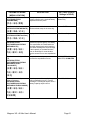
6.3. Controller with Display
Refer to Figure 6.3-1 for the front panel layout. The keypad consists of five buttons: , , ↵
(Enter), ESC (Escape) and “?” or Help key. The displays available consist of selection menus,
informational displays and editable displays.
Selection Menus – permit the display of multiple items. The up and down keypads allow the user
to scroll up and down among the selections. The item indicated by the right carrot is the preselected item. The ↵ selects the function and the display changes to that item. The ESC keypad
will take you back to the previous menu.
Information displays – display power plant information in a preformatted display. The information
is dynamic.
Editable Displays – permit the change of certain parameters within the power plant. The PIN or
password will need to be entered before parameters can be changed. Once the PIN is entered
it will not be required to be entered a second time that session. The up, down and enter keys
are used to modify the value.
The screen will revert to the language selection screen after a controller reset. Choices are
English and Chinese.
Magnum VS –48 Vdc User’s Manual
Page 28
If the keypad is not pressed for approximately 2 minutes the display will revert to the Status
display and the backlight will extinguish. It will also clear any PIN that may have been entered.
Pressing any key during this mode will cause the display of the Main Menu and permit
navigation among the menus.
Figure 6.3-1 Controller with Display
6.4. Operation using Local Display and Keypad Interface
The location, description, and factory programmed default value for each of the Magnum VS
system parameters is found in the table below. The menu location of a parameter screen is
shown in brackets, for example: [STATUS/RECT/Rect xx].
This table is organized
alphabetically by parameter name.
Magnum VS –48 Vdc User’s Manual
Page 29
Figure 6.4-1 Parameter Locations, Descriptions, and Default Values
PARAMETER NAME/
DESCRIPTION
[MENU LOCATION]
Alarms Item 1
{Status Only}
[ALARMS]
SETTINGS (Default
Settings in BOLD)
Display of up to 16 active alarms. Scroll
up or down to select individual alarms.
Alarm Status Only
The total battery capacity in amperehours of the entire battery array.
Normally specified at 20 hour discharge
rate.
0Ah – 10,000 Ah, 0 Ah
Battery current measured by the system
controller at the battery current shunt.
Battery Current Status
Only
One of three parameters that control the
dc output voltage. Set the Float Voltage
to the desired 25°C battery temperature
per the battery manufacturers
recommendations.
-56.5V - -47.0V, -54.00 V,
Lowers the system voltage so a
discharge test of the battery is
performed. ON – initiates a battery test.
Off – stops a test in progress.
Displays the results of the last battery
test.
ON, OFF
[告警]
Battery Capacity
[SETUP/BATTERY/
CAP]
[设置 / 电池 / 容量]
Battery Current
{Status Only}
[STATUS/BATTERY/
PARAMETERS]
[状态 / 电池 / 参数]
Battery Float Voltage
[SETUP/BATTERY/
VOLTAGE/FLOAT]
[设置 / 电池 / 电压 /
浮充]
Battery Functional Test
[SETUP/BATTERY/TEST]
[设置 / 电池 / 测试]
Battery Functional Test Result
[STATUS/BATTERY/TEST]
[状态 / 电池 / 测试]
Battery Maximum Recharge
Current
[SETUP/BATTERY/CURRENT]
[设置 / 电池 / 电流]
Battery Mode Status
[STATUS/BATTERY/MODE]
[状态 / 电池 / 模式]
One of three parameters that control the
dc output voltage. If Battery Current
surpasses the Maximum Battery
Recharge Current, the dc output voltage
will be reduced (the system limits the
charging current to this programmable
value).
This will display the condition of the
battery. Float is normal operation.
Discharge means the rectifiers are not
producing enough current and the
batteries are discharging. Equalizing
means the voltage is above float voltage
to give the batteries an equalize charge.
Magnum VS –48 Vdc User’s Manual
FAIL, PASS,
INTERRUPTED, IN
PROCESS, NOT
PERFORMED
0 – 500 A, 5 A
Float, Equalizing or
Discharge.
Page 30
PARAMETER NAME/
DESCRIPTION
[MENU LOCATION]
Battery Temperature
[STATUS/BATTERY/
PARAMETERS]
SETTINGS (Default
Settings in BOLD)
Battery temperature measured by the
system controller at the optional battery
temperature sensor probe.
Battery Temperature
Status Only
System date stored in the controller.
Used as a date stamp in the event log.
Current DATE
Displays the current controller date.
Date Status Only
Applies an overcharge to the battery to
equalize the specific gravity of a battery.
Auto equalization is initiated when the
controller determines that the batteries
have been discharged a set percentage
of their capacity or the batteries have
been on discharge for a set duration.
Use this screen to turn auto equalization
on.
Sets the time the ac input power has to
be off before equalization occurs.
ON, OFF
[状态 / 电池 /参数]
Date Setup
[SETUP/SYSTEM/TIME/DATE]
[设置 / 系统 / 时/日]
Date Status
[STATUS/SYSTEM/Time/Date]
[状态 / 系统 / 时/日]
Equalize Automatically On/Off
[SETUP/BATTERY/
VOLTAGE/EQUALIZATION/
METHOD/AUTO]
[设置 / 电池 /电压 /
均充 / 模式 / 自动]
Equalize Automatically on AC
Fail
[SETUP/BATTERY/
VOLTAGE/EQUALIZATION/
METHOD/AUTO/AC
FAIL/ON/OFF]
15 MINUTES – 360
MINUTES, 15 MINUTES
[设置 / 电池 /电压 /
均充 / 模式 / 自动
/自动]
Equalize Automatically on
Battery Discharge
[SETUP/BATTERY/
VOLTAGE/EQUALIZATION/
METHOD/AUTO/DISCHARGE]
Sets the percent of battery discharge
before equalization occurs. Percent
Discharge = Discharged ampere-hours /
Battery Capacity ampere-hours
5% - 50%, 30 %
[设置 / 电池 /电压 /
均充 / 模式 / 自动 /
交流故障]
Magnum VS –48 Vdc User’s Manual
Page 31
PARAMETER NAME/
DESCRIPTION
SETTINGS (Default
Settings in BOLD)
This setting defines the number of hours
the batteries will be equalized in all
methods of equalization. During the
initial stage of equalization the batteries
will have to be increased to the
equalization voltage. Once the battery
voltage and current meet equalization
parameters, the equalization duration
timer will start.
Applies an overcharge to the battery to
equalize the specific gravity of a battery.
Manual equalization is a one-time
equalization process. The operator turns
on manual equalization each time he
wishes an unscheduled equalization to
occur. To abort an automatic or periodic
equalization in progress, turn manual
equalization ON and then OFF.
Applies an overcharge to the battery to
equalize the specific gravity of a battery.
Periodic equalization is equalization after
a set number of days.
00 HOURS- 24 HOURS,
0 HOURS
[MENU LOCATION]
Equalization Duration
[SETUP/BATTERY/
VOLTAGE/EQUALIZATION/
DURATION]
[设置 / 电池 / 电压 /
均充 / 均充时间]
Equalize Manually
[SETUP/BATTERY/
VOLTAGE/EQUALIZATION/
METHOD/MANUAL]
[设置 / 电池 /电压 /
均充 / 模式 /手动]
Equalize Periodically
[SETUP/BATTERY/
VOLTAGE/EQUALIZATION/
METHOD/PERIODIC]
ON, OFF
ON, OFF;
0-180 Days, 180 Days
[设置 / 电池 /电压 /
均充 / 模式 /周期]
Equalization Voltage
[SETUP/BATTERY/
VOLTAGE/EQUALIZATION/
VOLTAGE]
The overcharge voltage that will be
applied to the battery
-56.5 V - -48.0 V, -56.0 V
[设置 / 电池 / 电压 /
均充 / 电压]
Language Selection
Pin Entry
[SETUP]
[设置]
PIN Setup
[SETUP/SYSTEM/SET PIN]
[设置 / 系统 / 码设置]
Rectifier Current Limit Status
{Status Only}
[STATUS/RECT]
The screen will revert to the language
selection screen after a reset. Choices
are English and Chinese.
Enter PIN to access setup menus.
Entering setup brings you to the PIN
entry screen. In-activity for two minutes
will de-activate system access.
Change PIN that the user will use to log
on to the system. If you change the PIN,
Do Not Forget It.
A display of the current limit alarm for the
individual rectifier. Scroll up or down to
select individual rectifiers.
0000 – 9999, 2222
0000 – 9999, 2222
Rectifier Current Limit
Status Only
[ 状态 / 模块]
Magnum VS –48 Vdc User’s Manual
Page 32
PARAMETER NAME/
DESCRIPTION
[MENU LOCATION]
Rectifier Current Output Status
{Status Only}
[STATUS/RECT]
SETTINGS (Default
Settings in BOLD)
A display of the dc output current for the
individual rectifier. Scroll up or down to
select individual rectifiers.
Rectifier Current Output
Status Only
A display of the fan fail alarm for the
individual rectifier. Scroll up or down to
select individual rectifiers.
Rectifier Fan Fail Status
Only
A display of the RFA alarm for the
individual rectifier. Scroll up or down to
select individual rectifiers.
Rectifier Fail Alarm Status
Only
The total system output current
(calculated as the sum of the individual
rectifier output currents).
System Current Status
Only
System temperature measured within the
controller.
System Temperature
Status Only
Actual power plant output voltage
measured by the controller at the output
of the rectifiers. This is the same voltage
at the front panel test points of the
controller.
System Voltage Status
Only
System time stored in the controller.
Used as a date stamp in the event log.
Current Time
Displays the current controller time.
Time Status Only
[ 状态 / 模块]
Rectifier Fan Fail Status
{Status Only}
[STATUS/RECT]
[ 状态 / 模块]
Rectifier Fail Alarm (RFA)
Status
{Status Only}
[STATUS/RECT]
[ 状态 / 模块]
System Current
{Status Only}
[STATUS/SYSTEM/
Parameters]
[状态 / 系统 /参数]
System Temperature
{Status Only}
[STATUS/SYSTEM/
Parameters]
[状态 / 系统 /参数]
System Voltage
{Status Only}
[STATUS/SYSTEM/
Parameters]
[状态 / 系统 /参数]
Time Setup
[SETUP/SYSTEM/Time/Date]
[设置 / 系统 / 时/日]
Time Status
[STATUS/SYSTEMTime/Date]
[状态 /系统 / 时/日]
Magnum VS –48 Vdc User’s Manual
Page 33
PARAMETERS
SYSTEM
27oC
-54.0V
100A
SYSTEM
15 : 27
23 DEC
TIME/DATE
STATUS
RECTIFIER
RECT03
FF
ENGLISH
ALARM 01
RECT 1 of N
m
SET PIN
SET PIN
2 2 2 2
MODE
BATTERY
TC: ON
MODE FLOAT
TEST
FUNCTIONAL
TEST PASS
TIME/DATE
15 : 27
23 DEC
CONFIRM PIN
2 2 2 2
TUE
2003
FLOAT
VOLTAGE
FLOAT
ENTER PIN
2 2 2
-54.0V
29A
OK CL
10.5A
SYSTEM
SETUP
BATTERY
29oC
TUE
2003
BATTERY
ALARMS
PARAMETERS
-54.0V
VOLTAGE
2
EQUALIZATION
CURRENT
RECHARGE
CURRENT
5A
VOLTAGE
EQUALIZATION
VOLTAGE -56.0V
DURATION
DURATION
0 HOURS
BATTERY
CAP
AUTO
OFF
EQUALIZATION
AC FAIL
AC FAIL
15 MINUTES
DISCHARGE
DISCHARGE
30 %
CAPACITY
OAh
AUTO
TEST
ON / OFF
FUNCTIONAL TEST
OFF
METHOD
Figure 6.4-2 Magnum VS English Display Tree
Magnum VS –48 Vdc User’s Manual
Page 34
MANUAL
MANUAL
OFF
EQUALIZATION
PERIODIC
PERIODIC
180 DAYS
OFF
系统
参数
系统
27oC
时/日
状态
模块03
模块
正常
风扇故障
15 : 27
23
电池
模式
电池温度补偿: 开
测试
功能测试
-54.0V
29A
29oC
星期二
2003
模式
浮充
10.5A
PIN码设置
PIN码修改
2 2 2 2
时/日
15 : 27
通过
PIN码确认
2 2 2 2
告警01
告警
RECT 1 of N
m
23
系统
设置
参数
限流
电池
中文
十二日
-54.0V
100A
PIN码输入
2 2 2
2
均充
电池
电流
容量
充电电流
2003
浮充
浮充
电压
十二日
星期二
5A
-54.0V
电压
均充电压
均充时间
均充时间
-56.0V
0
小时
电池容量
关
Figure 6.4-3 Magnum VS Chinese Display Tree
Page 35
交流故障
交流故障
放电
放电
15
功能测试
模式
Magnum VS –48 Vdc User’s Manual
自动均充
关
0Ah
自动
测试
开/关
30 %
手动
手动均充
关
周期
周期
关
180天
分钟
6.5. Controller without Display
This controller does not have a built in display and keypad. It does not use the fifth rectifier slot.
All parameter changes or viewing of status is made either locally using a PC or remotely by
interface to the network management card. Refer to Figure 6.5-1 for the front panel layout.
Figure 6.5-1 Magnum VS Controller without Display
6.6. Operation Using the RS-232 Comm Port
The front panel DB-9 connector provides a means to connect a PC to the controller locally to set
controller parameters and to view status. To connect to this port use a straight through cable
such as APC part number 0129-XX. A 0129-6 is included with this manual. . Refer to the
Network Management Card Quick Start Manual or the User's Guide supplied on the CD shipped
with the system for details on how to communicate to the controller using a terminal emulation
program like HyperTerminal(TM) or Procomm(TM
NOTE: The smart-signaling cable (940-0024 or 940-1524) referenced in the Quick Start Manual
and User's Guide does not apply to the Magnum VS. Use a straight through cable such as APC
part number 0129-XX. A 0129-6 is included with this manual.
Communication to the controller through the local serial port is accomplished via the network
management card's Control Console interface. This is a simple text based menu interface.
Magnum VS –48 Vdc User’s Manual
Page 36
6.7. Operation Using the 10/100 BaseT Ethernet Port
The RJ-45 10/100 Base-T port is primarily intended for connection to an intranet for remote
access to the DC power system. However with the use of a crossover cable or a hub, a direct
PC to 10/100 Base-T local connection may also be made.
After the Management Card is configured and running on your network, you can use several
different interfaces to access the Management Card: Web, Telnet, SNMP and FTP.
-The Web interface uses a web browser such as Microsoft ® Internet Explorer 5.0 (and higher)
or Netscape ® 4.0.8 (and higher) to configure Management Card options and to view DC power
system status, alarms and events.
-Telnet is used to access a Management Card’s Control Console and is the same user interface
available via the local RS-232 serial port.
-SNMP access is available after you add the PowerNet MIB to a standard SNMP MIB browser.
-FTP access is used to download new firmware to a Management Card, or to access a copy of a
Management Card’s event or data logs.
Complete documentation for the use of the management card accompanies the DC power
system in the form of a Quick Start Guide and a CD. The CD contains electronic copies of
User’s Manuals along with the necessary software utilities to support the management function.
Some of the functions supported by the network card are not supported by this power system.
6.8. Operation using Network Management Card Web Browser
Interface
The location, description, and factory programmed default value for each of the Magnum VS
system parameters accessible via a Web browser is found in the table below. The table also
shows all of the status and information screens with typical displays. The location of a
parameter screen is shown in brackets, for example: [Power Modules/Rectifiers]. This table is
organized alphabetically by parameter name.
Magnum VS –48 Vdc User’s Manual
Page 37
Figure 6.8-1 Parameter Locations, Descriptions, and Settings
PARAMETER NAME/
DESCRIPTION
[MENU LOCATION]
Alarms Item 1
{Status Only}
[System/Active Alarms]
•
•
•
Alarms Item 16
[System/Active Alarms]
Battery Current
{Status Only}
[System/DC Parameters]
Battery Discharge Alarm
[Batteries/Parameters]
Battery Discharge Threshold
[Batteries/Parameters]
Battery Float Voltage
[Batteries/Parameters]
Battery High Temperature
Alarm
[Batteries/Parameters]
Battery High Temperature
Threshold
[Batteries/Parameters]
Battery High Voltage Alarm
[Batteries/Parameters]
Battery High Voltage Threshold
[Batteries/Parameters]
Battery Low Temperature
Alarm
[Batteries/Parameters]
Battery Low Temperature
Threshold
[Batteries/Parameters]
Battery Low Voltage Alarm
[Batteries/Parameters]
Battery Low Voltage Threshold
[Batteries/Parameters]
SETTINGS (Default
settings in BOLD)
Display of up to 16 active alarms (a
typical alarm screen is shown).
•
•
•
Display of up to 16 active alarms (a
typical alarm screen is shown).
No Alarms
•
•
•
No Alarms
Battery current measured by the system
controller at the battery current shunt.
Status Only
Defines the output relay that is energized
if the battery discharge current exceeds
the programmed battery discharge
threshold.
An alarm is generated if the battery
discharge current exceeds this value.
One of three parameters that control the
dc output voltage. Set the Float Voltage
at 25°C battery temperature per the
battery manufacturers recommendations.
Defines the output relay that is energized
if the battery temperature exceeds the
Battery High Temperature threshold.
Battery Temperature is temperature
measured at the battery probe. An alarm
is generated if the battery temperature
exceeds this value.
Defines the output relay that is energized
if the dc output voltage rises above the
battery high voltage threshold.
An alarm will be reported if temperature
is lower than the temperature entered.
An alarm is generated if the dc output
voltage rises above this value.
Defines the output relay that is energized
if the Battery Temperature drops below
the battery Low Temperature threshold.
Battery Temperature is temperature
measured at the battery probe. An alarm
is generated if the battery temperature
drops below this value.
Defines the output relay that is energized
if the dc output voltage drops below the
battery low voltage threshold.
An alarm is generated if the dc output
voltage drops below this value.
Ignore, Minor, Major
Output Relay 1-6
Magnum VS –48 Vdc User’s Manual
0 A – 20A, 5 A
-56.5 – -47.0, -54.00 V
Ignore, Minor, Major
Output Relay 1-6
-100 °C – 200 °C, 40.0 °C
Ignore, Minor, Major
Output Relay 1-6
-40.00 V – -60.00 V, 58.00 V
Ignore, Minor, Major
Output Relay 1-6
-100 °C – 200 °C, -20.0
°C
Ignore, Minor, Major
Output Relay 1-6
-40.00 V – -60.00 V,
-44.00 V
Page 38
PARAMETER NAME/
DESCRIPTION
[MENU LOCATION]
Battery Max Recharge
{Status Only}
[System/DC Parameters]
Battery Maximum Recharge
Current
[Batteries/Parameters]
Battery Temperature
[System/DC Parameters]
Battery Temperature
Compensation High Knee
[Batteries/Parameters]
Battery Temperature
Compensation Low Knee
[Batteries/Parameters]
Battery Temperature
Compensation Method
[Batteries/Parameters]
Battery Temperature
Compensation Temperature
Coefficient
[Batteries/Parameters]
Circuit Breaker 1 Alias
[Distribution/Breakers]
•
•
•
Circuit Breaker 4 Alias
[Distribution/Breakers]
This is just a convenient place to view
the Battery Max Recharge Current
parameter. Go to Batteries/Parameters
to change setting.
One of three parameters that control the
dc output voltage. If Battery Current
surpasses the Maximum Battery
Recharge Current, the dc output voltage
will be reduced (the system limits the
charging current to this programmable
value).
Battery temperature measured by the
system controller at the optional battery
temperature sensor probe.
The temperature compensation high
knee is the point where there is no
additional battery voltage compensation
for further increases in temperature.
The temperature compensation low knee
is the point where there is no additional
battery voltage compensation for further
decreases in temperature.
One of three parameters that control the
dc output voltage. Activate “ON” or deactivate “OFF” battery temperature
compensation.
Temperature compensation coefficient
between low knee and high knee in
mV/cell/°C. (Compensation equals zero
at 25°C.)
An alternate name (alias) can be
assigned to Circuit Breaker 1 if desired.
This feature is supported by the standard
SNMP card monitor, but is not supported
by this dc system.
Circuit Breaker 1 Tripped
[Distribution/Breakers]
•
•
•
Circuit Breaker 4 Tripped
[Distribution/Breakers]
Defines the output relay that is energized
when Circuit Breaker 1 is tripped.
•
•
•
Defines the output relay that is energized
when Circuit Breaker 4 is tripped.
Communications Fail
Defines the output relay that is energized
if the System stops communicating with
the rectifiers. This feature is supported
by the standard SNMP card monitor, but
is not supported by this dc system.
Magnum VS –48 Vdc User’s Manual
SETTINGS (Default
settings in BOLD)
Status Only
0 – 10,000 A, 10 A
Status Only
0 °C – 100 °C, 40.0 °C
-100 °C – 100 °C, 0.0 °C
ON, OFF
-4.99 mV – 0 mV,
-3.00mV
Circuit Breaker 1
•
•
•
Circuit Breaker 4
Ignore, Minor, Major
Output Relay 1-6
•
•
•
Ignore, Minor, Major
Output Relay 1-6
Circuit Breaker 5-72 is not
used in this system.
Ignore, Minor, Major
Output Relay 1-6•
Page 39
PARAMETER NAME/
DESCRIPTION
[MENU LOCATION]
Current Limit Alarm Status
{Status Only}
[Power Modules/Rectifiers]
Date
[System/Date & Time]
Description 1
[System/DC Parameters]
Description 2
[System/DC Parameters]
Description 3
[System/DC Parameters]
Fail Safe
[Power Modules/Rectifiers]
The status will be “ON” if the rectifier has
been forced into its current limited mode.
Status Only
Internal network management card
calendar date. Used as a date stamp in
the web card event log.
Power plant identification - first line.
Current Date
Power plant identification - second line.
Magnum VS
This is not user edit-able.
Power System
This is not user edit-able.
This feature is supported
by the standard SNMP
card monitor, but is not
supported by this dc
system.
FUSE 1
Power plant identification - third line.
If the rectifiers fail to communicate with
the system, the rectifiers will output this
pre-defined voltage.
FUSE 1 Alias
[Distribution/Fuses]
•
•
•
FUSE 1 Alias
[Distribution/Fuses]
FUSE 1 Blown
[Distribution/Fuses]
•
•
•
FUSE 4 Blown
[Distribution/Fuses]
An alternate name (alias) can be
assigned to Fuse 1 if desired. This
feature is supported by the standard
SNMP card monitor, but is not supported
by this dc system.
Hardware Battery Current
Alarm
[Batteries Parameters]
Defines the output relay that is energized
if there is a hardware failure in the
battery current monitoring function. This
feature is supported by the standard
SNMP card monitor, but is not supported
by this dc system.
Defines the output relay that is energized
if there is a hardware failure in the
battery temperature monitoring function.
Program to Ignore if no battery
temperature probe is connected to J410.
Defines the output relay that is energized
if there is a conflict between the
commanded and sensed positions of the
LVD contactor. This feature is supported
by the standard SNMP card monitor, but
is not supported by this dc system.
Hardware Battery Temperature
Alarm
[Batteries Parameters]
Hardware LVD Alarm
[Batteries/LVD]
SETTINGS (Default
settings in BOLD)
Defines the output relay that is energized
when F1-4 is blown.
•
•
•
Defines the output relay that is energized
when F13-16 is blown.
Magnum VS –48 Vdc User’s Manual
•
•
•
FUSE 16
Ignore, Minor, Major
Output Relay 1-6
•
•
•
Ignore, Minor, Major
Output Relay 1-6
Fuse 5-16 is not used in
this system
Ignore, Minor, Major
Output Relay 1-6
Ignore, Minor, Major
Output Relay 1-6
Ignore, Minor, Major
Output Relay 1-6
Page 40
PARAMETER NAME/
DESCRIPTION
[MENU LOCATION]
Hardware System Voltage
Alarm
[Power Modules/Rectifiers]
Hardware Temperature Alarm
[System/DC Parameters]
High Temperature Alarm
[System/DC Parameters]
High Temperature Threshold
[System/DC Parameters]
High Voltage alarm
[Power Modules/Rectifiers]
High Voltage Threshold
[Power Modules/Rectifiers]
Imbalance Alarm
[Power Modules/Rectifiers]
Input Relay 1
[I/O/Input]
•
•
•
Input Relay 4
[I/O/Input]
Input Relay 1-4 Alias
[I/O/Input]
Input Relay 1-4 Delay
[I/O/Input]
Low Temperature Alarm
[System/DC Parameters]
Defines the output relay that is energized
if there is a hardware failure in the
system voltage monitoring function.
Defines the output relay that is energized
if there is a hardware failure in the
system temperature monitoring function.
Defines the output relay that is energized
if the System Temperature exceeds the
system high temperature threshold. Not
the same as battery temperature alarm.
Ambient temperature measured inside
the controller. An alarm will be reported
if temperature is higher than the
temperature entered. Not the same as
battery temperature threshold.
Defines the output relay that is energized
if the System Voltage is above the
System High Voltage threshold. Not the
same as battery voltage alarm.
DC voltage measured by the controller.
An alarm will be reported if voltage is
higher than the voltage entered. Not the
same as battery voltage threshold.
An alarm will be generated if the rectifiers
do not current share. This feature is
supported by the standard SNMP card
monitor, but is not supported by this dc
system.
Defines the output relay that is energized
when an external contact closure or
opening at the Input Relay 1 connection
changes state.
•
•
•
Defines the output relay that is energized
when an external contact closure or
opening at the Input Relay 4 connection
changes state.
This feature is supported by the standard
SNMP card monitor, but is not supported
by this dc system.
This feature is supported by the standard
SNMP card monitor, but is not supported
by this dc system.
Defines the output relay that is energized
if the System Temperature is below the
System Low Temperature threshold. Not
the same as battery temperature alarm.
Magnum VS –48 Vdc User’s Manual
SETTINGS (Default
settings in BOLD)
Ignore, Minor, Major
Output Relay 1-6
Ignore, Minor, Major
Output Relay 1-6
Ignore, Minor, Major
Output Relay 1-6
0 °C – 100 °C, 70.0 °C
Ignore, Minor, Major
Output Relay 1-6
-60 V – -40 V, -58.00 V
Ignore, Minor, Major
Output Relay 1-6
Ignore, Minor, Major
Output Relay 1-6
•
•
•
Ignore, Minor, Major
Output Relay 1-6
Input 1-4
0.00 Seconds
Ignore, Minor, Major
Output Relay 1-6
Page 41
PARAMETER NAME/
DESCRIPTION
SETTINGS (Default
settings in BOLD)
System Temperature is ambient
temperature measured inside the
controller. An alarm will be reported if
temperature is lower than the
temperature entered. Not the same as
battery temperature threshold.
Defines the output relay that is energized
if the System Voltage is below the
System Low Voltage threshold. Not the
same as battery voltage alarm.
System Voltage is bus voltage measured
by the controller. An alarm will be
reported if voltage is lower than the
voltage entered. Not the same as battery
voltage threshold.
If the unit has an LVD, but it is disabled,
the controller will not disconnect the LVD.
LVD Reset (reconnect) threshold voltage.
-100 °C – 100 °C, 0.0 °C
LVD Trip (disconnect) threshold voltage.
-56 V – -40 V, -42.00 V
Not available on this system.
Disable
Not available on this system.
0.00 V
Not available on this system.
0.00 V
Defines the output relay that is energized
when the controller opens the LVD. If
unit has a battery LVD, no power will be
available to turn on any Output Relays.
Output Relay 1 Alarm can be “mapped”
to activate other output relays (“Ignore”
activates no additional relays).
Ignore, Minor, Major
Output Relay 1-6
[MENU LOCATION]
Low Temperature Threshold
[System/DC Parameters]
Low Voltage Alarm
[Power Modules/Rectifiers]
Low Voltage Threshold
[Power Modules/Rectifiers]
LVD 1 Option
[Batteries/LVD]
LVD 1 Reset
[Batteries/LVD]
LVD 1 Trip
[Batteries/LVD]
LVD 2 Option
[Batteries/LVD]
LVD 2 Reset
[Batteries/LVD]
LVD 2 Trip
[Batteries/LVD]
LVD Alarm
[Batteries/LVD]
Output Relay 1 Alarm
[I/O/Output]
Output Relay 2 Alarm
[I/O/Output]
•
•
•
Output Relay 6 Alarm
[I/O/Output]
Output Relay 2-6 Alarm can be “mapped”
to activate other output relays (“Ignore”
activates no additional relays). Alarms
that are mapped to output relay 2-6 are
not supported by hardware. The network
management card supports programming
these relays. These relays can be
mapped to the hardware relays minor
and major.
Magnum VS –48 Vdc User’s Manual
Ignore, Minor, Major
Output Relay 1-6
-60 V – -40 V, -50.00 V
Enable, Disable
-56 V – -40 V, -50.00 V
Ignore, Minor, Major
Output Relay 1-6
Ignore, Minor, Major
Output Relay 1-6
•
•
•
Ignore, Minor, Major
Output Relay 1-6
Page 42
PARAMETER NAME/
DESCRIPTION
[MENU LOCATION]
Output Relay 1 Alias
[System/Out-Rly/Alias]
•
•
•
Output Relay 6 Alias
[System/Out-Rly/Alias]
Output Relay 1 Delay
[I/O/Output]
•
•
•
Output Relay 6 Delay
[I/O/Output]
Rectifier 1-of-N Alarm
[Power Modules/Rectifiers]
Rectifier 2-of-N Alarm
[Power Modules/Rectifiers]
Rectifier Configuration Alarm
[Power Modules/Rectifiers]
Rectifier Current Limit Alarm
[Power Modules/Rectifiers]
Rectifier Current Output Status
{Status Only}
[Power Modules/Rectifiers]
Rectifier Description
{Status Only}
[Power Modules/Rectifiers]
Rectifier Diagnostic Alarm
[Power Modules/Rectifiers]
Rectifier Fan Fail Alarm
[Power Modules/Rectifiers]
Rectifier Fan Fail Alarm Status
{Status Only}
[Power Modules/Rectifiers]
An alternate name (alias) can be
assigned to Output Relay 1 if desired.
•
•
An alternate name (alias) can be
assigned to Output Relay 6 if desired.
Delay between sensing of the alarm
condition and activation of the mapped
relay. An alarm condition must exist for
longer than the delay to be activated.
SETTINGS (Default
settings in BOLD)
Output Relay 1
•
•
•
Output Relay 6
0.00 seconds – 600.00
seconds, 0.00 seconds
Defines the output relay that is energized
if Rectifier Fail 1-of-N alarm occurs. This
is a special rectifier alarm group that
signifies that one rectifier has at least
one alarm condition.
Defines the output relay that is energized
if Rectifier Fail 2-of-N alarm occurs This
is a special rectifier alarm group that
signifies that more than one rectifier has
at least one alarm condition.
Defines the output relay that is that is
energized a rectifier is added to any
empty slot after the dc system is
powered up or configured. This feature
is supported by the standard SNMP card
monitor, but is not supported by this dc
system.
Defines the output relay that is energized
or special rectifier alarm group n of N that
occurs when a rectifier has been forced
into the current limited mode.
A display of the dc output current for the
individual rectifier.
Ignore, Minor, Major
Output Relay 1-6
Displays the model number of the
installed rectifier.
Status Only
This feature is not needed in this
particular configuration.
Defines the output relay that is energized
or special rectifier alarm group n of N that
occurs when a rectifier fan has failed.
The status will be “ON” if the rectifier fan
has failed.
Ignore, Minor, Major
Output Relay 1-6, n of N
Ignore, Minor, Major
Output Relay 1-6, n of N
Magnum VS –48 Vdc User’s Manual
Ignore, Minor, Major
Output Relay 1-6
Ignore, Minor, Major
Output Relay 1-6, n of N
Ignore, Minor, Major
Output Relay 1-6, n of N
Status Only
Status Only
Page 43
PARAMETER NAME/
DESCRIPTION
[MENU LOCATION]
Rectifier Fault Alarm (RFA)
Status
{Status Only}
[Power Modules/Rectifiers]
Rectifier RFA Alarm
[Power Modules/Rectifiers]
Rectifier Standby Alarm
[Power Modules/Rectifiers]
Rectifier Standby Alarm Status
{Status Only}
[Power Modules/Rectifiers]
Remote Configurable
[System/DC Parameters]
Store Configuration
[Power Modules/Rectifiers]
System Current
{Status Only}
[System/DC Parameters]
System Temperature
{Status Only}
[System/DC Parameters]
System Voltage
{Status Only}
[System/DC Parameters]
Temperature Display Units
[System/Preferences]
Time
[System/Date & Time]
SETTINGS (Default
settings in BOLD)
The status will be on if the rectifier output
has failed.
Status Only
Defines the output relay that is energized
or special rectifier alarm group n of N that
occurs when a rectifier output has failed.
Defines the output relay that is that is
energized or special rectifier alarm group
n of N that occurs when the controller is
holding a rectifier in the standby mode.
The status will be “ON” if the controller is
holding the rectifier in the standby mode.
Ignore, Minor, Major
Output Relay 1-6, n of N
This allows settings to be made using the
SNMP interface card. Disabling this
feature allows changes to be made
through the local interface only. Status
and parameters are still displayed.
This feature is supported by the standard
SNMP card monitor, but is not supported
by this dc system.
The total system output current
(calculated as the sum of the individual
rectifier output currents).
System temperature measured within the
controller.
Voltage readout measured by the
controller at the output of the rectifiers.
This voltage is based on calculations
performed by the controller based on the
Battery Float, Battery Temperature
Compensation and Battery Maximum
Recharge parameter settings.
Enables selection of Fahrenheit or
Celsius temperature scale (Fahrenheit
“OFF” displays readings in °C).
Network management card Internal
system clock time (24-hour format).
Used as a time stamp in the web card
event log.
Ignore, Minor, Major
Output Relay 1-6, n of N
This feature is supported
by the standard SNMP
card monitor, but is not
supported by this dc
system.
Enabled, Disabled
Enable, Disable
Status Only
Status Only
Status Only
Fahrenheit, Celsius
Current Time
6.9. LVD Operation
In order to prevent damage to the battery due to deep discharge, the dc power system has a
Low Voltage Disconnect (LVD). When the battery voltage reaches the threshold set by the LVD
1 Trip Voltage setting during discharge, the dc power system will activate the LVD contactor to
disconnect the battery from the system. The LVD will remain open until ac power is restored to
Magnum VS –48 Vdc User’s Manual
Page 44
the system and the bus voltage reaches the level defined by the LVD 1 Reset Voltage variable.
The LVD control can be disabled on the LVD parameters screen in the controller.
The LVD will not be energized until a battery string is installed with the correct polarity and the
battery disconnect switch is turned on. This will prevent the battery from being hooked up
backwards and damaging the rectifiers and/or the loads. Once the battery is connected
correctly and the LVD is closed, the LVD will open only in low voltage situations. The battery
connections are to be used for the battery only.
6.10.Programming Output Relays
Any alarm condition such as System High Voltage Alarm, Battery Discharge Alarm or Rectifier 1
of n Alarm can be programmed to any of the eight output relays. Programming alarms to the
output relays 1-6 will give a much better idea of what the failure is before actually visiting the
site. Using the default programming, over twenty conditions could cause activate a minor relay.
However, if you program Battery Discharge Alarm to Output Relay 1, you will know exactly what
the alarm is just by knowing that output relay 1 is on. The network management card also
displays the output relays individually and can be set up to e-mail these messages.
Output relay mapping options are Ignore, Major, Minor and Output Relay 1-6. To program the
alarm to an output relay find the alarm setup screen for the desired alarm from the table in
Figure 6.8-1. The Ignore setting will not send an alarm to any display or relay. Programming
the alarm to Major, Minor or Output Relay 1 will send the alarm to the relay output connector on
the back of the plant, turn on the appropriate front panel LED, and will send the alarm to the
network management card. Programming the alarm to Output Relay 2-6 will not send the alarm
to the relay output connector on the back of the plant, but will turn on the front panel Out Relay
LED, and will send the alarm to the network management card. For instance, go to the
Batteries / Parameters screen and program Battery Discharge Alarm to Output Relay 1. When
the battery discharge current goes above the default setting of 5 Amps, the alarm will come on,
the Out Relay contact will energize, the front panel Out Relay LED will come on and the network
management card will report Output Relay 1 is on.
Most alarms are originally assigned to a minor or major relay. Usually it is desirable to keep the
minor and major assignments when programming to the output relays. To do this, go to the
output relay-programming screen and map the relay back to the desired minor or major relay.
For instance, go to the I/O / Output screen and program Relay 1 to Minor Relay. When the
battery discharge current goes above the default setting of 5 Amps, the alarm will come on, the
Out Relay contact will energize, the Out Relay LED will come on and the network management
card will report Output Relay 1 is on. In addition, the Minor Relay contact will energize, the front
panel Minor LED will come on and the network management card will report the Minor Relay is
on. With this scheme of programming, you will know that you have a minor alarm and
specifically that the batteries are discharging.
Out Relay 1-6 can be renamed using the Relay Alias setup screen. Each relay name can be up
to sixteen characters in length. This name will not appear in the alarm summary, but will appear
in the messages generated by the network management card. This can be used to give specific
Magnum VS –48 Vdc User’s Manual
Page 45
information on the exact nature of the active alarm. Using the example above, if you use the
default programming the message “A minor relay in the power plant has been activated.” Using
the relay mapping and aliasing you could get the additional message “An output relay (1, Batt
Discharge) for the power plant has been activated.
Magnum VS –48 Vdc User’s Manual
Page 46
7
Preventive Maintenance
Preventive Maintenance is typically performed on a quarterly basis.
7.1. Equipment
1. 4 Digit voltmeter.
2. Clamp-on ampere meter.
3. Standard Insulated tools.
7.2. Inspection
Environmental Inspection
1.
2.
3.
4.
Ensure the dc system environment is suitable for operation.
Ensure that there is sufficient clearance around the system for service.
Ensure that there is no sign of damage to the dc system.
Contact monitoring personnel or disable system alarms before servicing the unit. This
will allow the unit to be serviced without creating false alarms.
System Visual and Safety Inspection
WARNING: Hazardous energy levels are present on bare conductors in the
dc distribution connection area of the plant. Accidental shorting of distribution
conductors can cause arcing and high currents that can cause serious burns
or other physical harm. It is recommended that:
• Any jewelry, rings or watches be removed while working on this
equipment.
• Handles of all wrenches, screwdrivers, cutters and pliers are insulated.
1.
2.
3.
4.
Ensure that the dc wiring is properly installed, sized, terminated and identified.
Ensure that the ac wiring is properly installed, sized, terminated and identified.
Ensure that the battery wiring is properly connected to the System.
Ensure that the dc output over-current protection devices are adequate for the size of
wiring installed.
5. Ensure that the dc Positive is bonded to central office ground (- 48 volt system).
6. Note the resistance of the ground bond.
7. Note any currents flowing in the ground.
8. Record ambient temperature.
9. Verify that the battery polarity is correct.
10. If battery disconnect devices are present, note the following for each device:
a) DC voltage rating.
b) DC current rating
Magnum VS –48 Vdc User’s Manual
Page 47
c) Interrupting Current Rating
Battery Visual and Safety Inspection
1. Check that the battery temperature probe is firmly attached to the battery.
2. Check the mechanical integrity of the battery framing, racking, or cabinet. Tighten
where necessary.
3. If there is a battery disconnect device fitted, ensure that it is properly connected and
protected.
4. Check the general appearance and cleanliness of the battery. Clean if necessary.
Use only approved cleaning materials.
5. Visually inspect each cell for the following, and clean and neutralize if necessary.
Document discrepancies on Site form accordingly.
a. Cracks.
b. Case leaks.
c. Post-seal leaks.
d. Pressure relief valve leaks (VRLA only).
e. Case swelling (VRLA only).
f. Terminal corrosion and connector corrosion.
6. Check the torque of all battery inter-cell connector in accordance with specifications.
Re-torque if necessary (annual only).
7. Measure and record ambient temperature.
7.3. Test
System Voltage Test
1. Verify with a voltmeter directly attached to the dc bus that the system voltage is correct.
2. System voltage should also agree with the battery float voltage set up in the battery
parameters section. Be sure to take into account the effects of temperature
compensation and battery recharge current limit.
Rectifier Current Share Test
Verify that the highest rectifier current and the lowest current are within 5 A of each other.
System Current Test
Verify the System current equal to the total of the rectifier currents. System current should
equal the total current of the loads as well as any battery current.
Rectifier Alarm Test
1. Verify that all of the rectifiers report RFA Alarm is off.
2. Remove 1 rectifier and verify that you get a Minor alarm for Rect 1 of n failure on the
controller and the customer remote alarm panel.
Magnum VS –48 Vdc User’s Manual
Page 48
3. Remove the second rectifier and verify that you get a Major alarm for Rect 2 of n failure
on the controller and the customer remote alarm panel.
4. After the fan has completely stopped spinning, insert a plastic pen or plastic screwdriver
into the fan blade of one of the rectifiers and reinsert both rectifiers
5. Verify that you get the fan fail alarm on controller and the customer remote alarm panel.
6. Remove the fan fail device.
System Temperature Test
Verify that the system temperature is correct.
Battery Current Test
1.
2.
3.
4.
Measure the battery current with a clamp-on meter.
Verify that the battery current is below 5 A.
Verify that the displayed battery current is within + 5 A.
Determine the total battery capacity at the site:
Cells connected in series make up a string, and the capacity is determined by the
capacity of a single cell. Add Ah capacity for all strings connected in parallel.
5. Determine the Max. Batt. Recharge rate:
Divide Total battery capacity by 20 hours and enter it in the appropriate box on the Site
Form.
6. Verify that the Max. Batt. Recharge rate is set to the calculated value.
7. Remove ac power to the rectifiers purposely causing the battery discharge alarm to come
on.
8. Verify that the System Current is 0 + 5 A.
9. Verify that the battery current is within 5 % of the system current recorded previously.
10. Restore ac power to the rectifiers.
Battery Temperature Test
If the battery temperature probe is used in this system, verify that the battery temperature is
correct.
LVD Test
1.
2.
3.
4.
Ensure that the LVD parameters are set to proper values.
Record the LVD trip point.
To test the LVD function, set the LVD Trip to –56.00 Vdc.
The LVD should have dropped out (opened). Verify it by monitoring the voltage at the
battery connection.
5. Verify that the LVD Open Alarm is registered on the controller and at the customer
remote alarm panel.
6. Reset the LVD Trip to the original setting.
7. Verify that the LVD Open Alarm has been removed.
Magnum VS –48 Vdc User’s Manual
Page 49
Battery Preventive Maintenance Procedure
The purpose of the preventive maintenance is to ensure that the battery is in good, working
condition. The observations, measurements, and tests performed are designed to determine
the “state of health” of the battery. It will also allow for the prediction of future performance and
preempt possible failure.
1. Measure the float charge voltage.
a. At the power bay bus.
b. At the battery.
c. Reset voltage if necessary.
2. Measure the float current on each battery cable. If it is fluctuating, measure maximum
and minimum.
3. Measure the ac ripple voltage at the battery.
4. Measure the float voltage of each cell or monoblock. Record the battery memory location
allocated on the battery tester.
5. Perform a load test on each cell or monoblock and measure the internal cell resistance
and inter-cell resistance of each cell or monoblock.
6. Ensure that all protective covers are replaced and that the battery is electrically nonhazardous to personnel that could be working in the vicinity
7.4. Final Inspection:
5. Verify that the interior and exterior of the system is clean and free from debris.
6. Ensure all wires connected and bolts are properly tightened.
7. Ensure the following the User, Service, and Calibration parameters are set properly on
the controller (default settings are in parenthesis):
LVD
LVD1 Trip
LVD1 Reset
Battery Parameters
Discharge Threshold
Float Voltage
Maximum Recharge
Compensation Method
8. Verify on the status menu that the system is functioning correctly with no alarms.
9. Be sure to leave the site as orderly and neat as possible.
Magnum VS –48 Vdc User’s Manual
Page 50
8
ALARM/
DESCRIPTION
Alarm Summary
DEFAULT SETTINGS
[MENU LOCATION]
Battery Discharge Alarm
[Batteries/Parameters]
Battery High Temp Alm
[Batteries/Parameters]
Battery Low Temp Alm
[Batteries/Parameters]
Battery LV Alm
[Batteries/Parameters]
Circuit Breaker Alm 1
[Distribution/Breakers]
Circuit Breaker Alm 2
[Distribution/Breakers]
Circuit Breaker Alm 3
[Distribution/Breakers]
Circuit Breaker Alm 4
[Distribution/Breakers]
FUSE Alm 1
[Distribution/Fuses]
FUSE Alm 2
[Distribution/Fuses]
FUSE Alm 3
[Distribution/Fuses]
FUSE Alm 4
[Distribution/Fuses]
Hardware Batt Temp Alm
[Batteries Parameters]
Hardware Sys Volt Alm
[Power Modules/Rectifiers]
Hardware Sys Temp Alm
[System/DC Parameters]
System HT Alm
[System/DC Parameters]
System HV Alm
[Power Modules/Rectifiers]
Input Relay 1
[I/O/Input]
•
•
•
Input Relay 4
[I/O/Input]
The battery discharge current exceeds
the programmed battery discharge
threshold.
The battery temperature exceeds the
Battery High Temperature threshold.
The Battery Temperature is below the
battery Low Temperature threshold.
The dc output voltage is below the
battery low voltage threshold.
The top Circuit Breaker in the top shelf is
tripped.
The bottom Circuit Breaker in the top
shelf is tripped
The top Circuit Breaker in the bottom
shelf is tripped.
The bottom Circuit Breaker in the bottom
shelf is tripped
Any of Fuse 1 through 4 is blown.
Major
Any of Fuse 5 through 8 is blown.
Major
Any of Fuse 9 through 12 is blown.
Major
Any of Fuse 13 through 16 is blown.
Major
There is a hardware failure in the battery
temperature monitoring function.
There is a hardware failure in the system
voltage monitoring function.
There is a hardware failure in the system
temperature monitoring function.
The System Temperature exceeds the
system high temperature threshold. Not
the same as battery temperature alarm.
The System Voltage is above the System
High Voltage threshold. Not the same as
battery high voltage alarm.
An external contact closure at the Input
Relay 1 connection.
•
•
•
An external contact opening at the Input
Relay 4 connection.
Minor
Magnum VS –48 Vdc User’s Manual
Minor
Minor
Minor
Major
Major
Major
Major
Major
Minor
Minor.
Minor
Minor
Ignore
•
•
•
Ignore
Page 51
ALARM/
DESCRIPTION
DEFAULT SETTINGS
[MENU LOCATION]
System LT Alm
[System/DC Parameters]
Low Voltage Alarm
[Power Modules/Rectifiers]
LVD Alarm
[Batteries/LVD]
User Output Relay 1 Alarm
[I/O/Output]
Rectifier 1-of-N Alm
[Power Modules/Rectifiers]
Rectifier 2-of-N Alm
[Power Modules/Rectifiers]
Rectifier Current Limit Alarm
[Power Modules/Rectifiers]
Rectifier Fan Fail Alm
[Power Modules/Rectifiers]
Rectifier RFA Alarm
[Power Modules/Rectifiers]
The System Temperature is below the
System Low Temperature threshold. Not
the same as battery temperature alarm.
The System Voltage is below the System
Low Voltage threshold. Not the same as
battery voltage alarm.
The controller opened the LVD. If unit
has a battery LVD, no power will be
available to turn on any Output Relays.
Output Relay 1 Alarm can be “mapped”
to activate other output relays (“Ignore”
activates no additional relays).
Rectifier Fail 1-of-N alarm occurs. This is
a special rectifier alarm group that
signifies that one rectifier has at least
one alarm condition.
Rectifier Fail 2-of-N alarm occurs This is
a special rectifier alarm group that
signifies that more than one rectifier has
at least one alarm condition.
A rectifier is in the current limited mode.
n of N
A rectifier fan has failed.
n of N
A rectifier output has failed.
n of N
Magnum VS –48 Vdc User’s Manual
Minor
Minor
Major
Ignore
Minor
Major
Page 52
9
Specifications
The overall system specifications can vary, depending upon the number of rectifier modules.
Note that some specification items are provided on a “per rectifier” basis and must be combined
or totaled for a given system configuration.
9.1. AC Input
TWF0500H54B Rectifier
Input Voltage Range
85 – 264 Vac
AC Frequency Range
47 – 63 Hz
Apparent Power Factor
99% Typical, 98% Minimum
Input Current (per Rectifier)
5.5 A @ 115Vac
3.7 A @ 230Vac
Turn on Time
2 Seconds
Magnum VS 50 Power System
Input Voltage Range
85 – 264 Vac
AC Frequency Range
47 – 63 Hz
Apparent Power Factor
99% Typical, 98% Minimum
Input Current
27.5 A @ 115 Vac
18.5 A @ 230 Vac
Magnum VS –48 Vdc User’s Manual
Page 53
Magnum VS 100 Power System
Input Voltage Range
85 – 264 Vac
AC Frequency Range
47 – 63 Hz
Apparent Power Factor
99% Typical, 98% Minimum
Input Current
55 A @ 115 Vac
37 A @ 230 Vac
9.2. DC Output
TWF0500H54B Rectifier
Output Voltage (factory set) 54.5 Vdc
Operating Voltage Range
44 – 58 Vdc
Efficiency
85% Typical
Over Voltage Protection
59.5 Vdc
Output Current per
Rectifier
9.0 A Minimum Continuous at 115 Vac Input
10.5 A Minimum Continuous at 230 Vac Input.
Current Limit
9.3 A Maximum at 115 Vac Input
11.0 A Maximum at 230 Vac Input.
Power Output per Rectifier
@ 54.5Vdc
490 W Continuous at 115 Vac Input
570 W Continuous at 230 Vac Input
Magnum VS –48 Vdc User’s Manual
Page 54
Magnum VS 50 Power System
Output Voltage (factory
programmed)
54.0 Vdc
Operating Voltage Range
47 – 56.5 Vdc
Rated Output Current
50 A
Efficiency
85% Typical
Over Voltage Protection
59.5 Vdc
Output Current
45 A Minimum Continuous at 115 Vac Input
52.5 A Minimum Continuous at 230 Vac Input.
Current Limit
46.5 A Maximum at 115 Vac Input
55.0 A Maximum at 230 Vac Input.
Power Output @ 54.5 Vdc
2450 W Continuous at 115 Vac Input
2850 W Continuous at 230 Vac Input
Magnum VS 100 Power System
Output Voltage (factory
programmed)
54.0 Vdc
Operating Voltage Range
47 – 56.5 Vdc
Rated Output Current
100 A
Efficiency
91% Typical
Over Voltage Protection
59.5 Vdc
Output Current
90 A Minimum Continuous at 115 Vac Input
105 A Minimum Continuous at 230 Vac Input.
Current Limit
93 A Maximum at 115 Vac Input
110 A Maximum at 230 Vac Input.
Power Output per Rectifier
@ 54.5Vdc
4900 W Continuous at 115 Vac Input
5700 W Continuous at 230 Vac Input
Magnum VS –48 Vdc User’s Manual
Page 55
9.3. Controls and Indicators
TWF0500H54B Rectifier
Input Healthy LED
AC power present.
Output Healthy LED
DC output voltage between 39.5 to 59.5 Vdc.
Current Limit LED
On when rectifier is in current limit.
Overvolts LED
On when rectifier is above 57 Vdc. (Must be powered down to
reset)
Magnum VS Controller
DC OK (Green)
On when voltage is between 50 and 57 Vdc.
Major (Red)
On when Major Relay is de-energized*
Minor (Yellow)
On when Minor Relay is energized
Out Relay 1 (Red)
On when Output Relay 1 is energized
(Flashing Green)
Watchdog LED
* Major relay is energized in normal operation. If all power fails, major relay will lose power
and the contacts will change state, signifying an alarm.
9.4. Mechanical
TWF0500H54B Rectifier
Dimensions (Overall)
5 in (12.7 cm) high x 2.75 in (7 cm) wide x 10.5 in (26.7 cm)
deep
Dimensions (not including
faceplate or connectors)
5 in (12.7 cm) high x 2.5 in (6.3 cm) wide x 9.4 in (24 cm)
deep
Weight
4 lb (1.8 kg)
Color
Black front, Yellow zinc sides and back
Mounting
Hot swappable. Secured with 2.5 mm captive screws
Magnum VS 50 Power System
Magnum VS –48 Vdc User’s Manual
Page 56
Dimensions
5-1/4 in (13.3 cm) high x 17-1/4 in (43.8 cm) wide x 13 in (33cm) deep
Weight
15 lb. (6.8 kg)
Color
Black Front, Yellow zinc sides and back
Mounting
19” Rack Mounting (23” Optional)
Magnum VS 100 Power System
Dimensions
10-1/2 in (26.6 cm) high x 17-1/4 in (43.8 cm) wide x 13 in (33cm) deep
Weight
30 lb. (13.6 kg)
Color
Black Front, Yellow zinc sides and back
Mounting
19” Rack Mounting (23” Optional)
9.5. Environmental
Ambient Temperature
Humidity
Altitude
(Operating)
-40ºC to +55ºC (+65ºC with reduced power output)
(Storage)
-45ºC to +85ºC
(Operating)
0 – 85% RH (non-condensing)
(Storage)
0 – 95% RH (non-condensing)
(Operating)
3000 m (9840 ft.)
(Storage)
10000 m (39370 ft.)
Magnum VS –48 Vdc User’s Manual
Page 57
9.6. Compliance
NEBS
Level 3 (Pending)
Safety
UL 60950
CE Marked to Low Voltage Directive (EN60950)
EMC
FCC Part 15 Class A
EN55022 Class A, EN55024
EN61000-3-2, EN61000-3-3
Magnum VS –48 Vdc User’s Manual
Page 58
10
APC Worldwide Customer Support
Customer Support for this or any other APC product is available at no charge. You can contact
APC Customer Support in any of the following ways:
•
Use an APC web page to find answers to frequently asked questions (FAQs), to access
documents in the APC Knowledge Base, and to submit customer support requests.
o http://www.apc.com
Connect by links to APC web pages for specific countries and regions, each of
which provides customer support information.
o http://www.apc.com/support/
Submit customer support requests.
o http://www.apc.com/support/contact
For e-mail addresses and local, country-specific, customer support telephone
numbers worldwide.
•
Contact Local or regional APC Customer Support by telephone.
US and Canada
China
Austria
Belgium
Czech Republic
Denmark
Finland
France
Greece
Hungary
Ireland
Israel
Italy
Luxembourg
•
1-(800) 800-4272
800 810 0160
0800 999670
0800 40677
800 102063
80 884953
0800 115308
0805 110053
00800 125924
0640 200262
1890 272877
1800 9452206
800 22091
800 22091
Netherlands
Norway
Poland
Portugal
Russia
Slovak Republic
South Africa
Spain
Sweden
Switzerland
Turkey
United Kingdom
Ukraine
Worldwide
0800 0232509
800 10436
0801 345917
800 853182
8800 2002722
0800 172063
086 1 272877
800 853182
0200 895283
0800 111469
800 2612135
0800 2799254
8800 5027220
(+1) 1 401 789-5735
Contact the APC representative or other distributor from whom you purchased your APC
hardware device or APC software application for information on how to obtain local
customer support.
Magnum VS –48 Vdc User’s Manual
Page 59
11
Limited Product Warranty
The limited warranty provided by American Power Conversion Corporation ("APC") in this Statement of Limited Factory
Warranty applies only to Products Buyer purchases for your commercial or industrial use in the ordinary course of Buyer's
business.
APC PRODUCTS COVERED ("Product or Products"):
Magnum VS 50
Magnum VS 100
Terms of Warranty:
APC warrants that the Product shall be free from defects in materials and workmanship, for a period of two (2) years from the date of
shipment.
Warranty Procedure
If initial physical inspection results in identification of a material or workmanship flaw(s) that could impair Product performance as defined by
APC’s electrical and physical specification in effect at the time of shipment, and if this flaw(s) is not due to transportation damage or installation
abuse, contact APC or call the 24-hour emergency number, (800) 800 4APC, to request assistance.
You will be provided either a) an RMA number with instructions for return of the equipment or component(s) to the APC factory service center, FOB
destination, freight pre-paid, for examination, or b) for non-returnable systems and equipment, notice to wait until an APC authorized service
representative arrives at the site to inspect the equipment. Repaired or advance replacement modules or circuit components will normally be
available within 24 to 48 hours of receipt of equipment or RMA.
Warranty Obligations - Repair or Replacement
If, during the warranty period, the Product is found to be physically or electrically faulty due to defective materials or workmanship, the defective
Product(s) or component(s) will be repaired or replaced at the sole option of APC. If the procedure outlined above for contacting APC immediately
after identifying a material or workmanship flaw(s) that could impair Product performance has been properly followed, such repair or replacement of
Product(s) or component(s) shall include all charges for replacement materials or repair labor. Costs incurred for replacement installation including,
but not limited to, installation equipment, travel expenses of an APC representative(s), and costs of installation material transportation expenses are
not included as a part of this warranty. Any replacement components or materials furnished under this warranty may be new or factory
remanufactured. THIS WARRANTY DOES NOT COVER CONSUMABLES OR PREVENTATIVE MAINTENANCE ITEMS. REPAIR OR
REPLACEMENT OF A DEFECTIVE PRODUCT OR COMPONENT THEREOF DOES NOT EXTEND THE ORIGINAL WARRANTY
PERIOD.
Exclusions and Limitations
This Warranty is extended to the first person, firm, association or corporation for whom the APC Product specified herein has been
bought. This Warranty is not transferable or assignable without the prior written permission of APC.
This limited warranty does not cover damage due to external causes, including accident, abuse, misuse, servicing not authorized by
APC, usage not in accordance with Product instructions, failure to perform preventative maintenance, and problems cause by use of
parts and components not supplied by APC. This limited warranty does not apply to Products from which the serial numbers have been
removed, or to conditions resulting from improper use, accidents, external causes, including installation, relocation of hardware, service
or modifications not performed by APC or its authorized service providers, or operation outside the environmental parameters specified
for the Product. APC does not warrant that the operation of any Product will be uninterrupted or error free. Warranty service may not be
performed if APC or other suppliers reasonably believe conditions at the Buyer's site represent a safety or health risk.
THERE ARE NO WARRANTIES, EXPRESS OR IMPLIED, BY OPERATION OF LAW OR OTHERWISE, OF PRODUCTS SOLD,
SERVICED OR FURNISHED UNDER THIS AGREEMENT OR IN CONNECTION HEREWITH. APC DISCLAIMS ALL IMPLIED
WARRANTIES OF MERCHANTABILITY, SATISFACTION AND FITNESS FOR A PARTICULAR PURPOSE. APC’S EXPRESS
WARRANTIES WILL NOT BE ENLARGED, DIMINISHED, OR AFFECTED BY AND NO OBLIGATION OR LIABILITY WILL ARISE
OUT OF, APC’S RENDERING OF TECHNICAL OR OTHER ADVICE OR SERVICE IN CONNECTION WITH THE PRODUCTS. THE
FOREGOING WARRANTIES AND REMEDIES ARE EXCLUSIVE AND IN LIEU OF ALL OTHER WARRANTIES AND REMEDIES.
THE WARRANTIES SET FORTH ABOVE, CONSTITUTE APC’S SOLE LIABILITY AND YOUR EXCLUSIVE REMEDY FOR ANY
BREACH OF SUCH WARRANTIES. APC’S WARRANTIES RUN ONLY TO YOU AND ARE NOT EXTENDED TO ANY THIRD
PARTIES. IN NO EVENT SHALL APC, ITS OFFICERS, DIRECTORS, AFFILIATES OR EMPLOYEES BE LIABLE FOR ANY FORM
OF INDIRECT, SPECIAL, CONSEQUENTIAL OR PUNITIVE DAMAGES, ARISING OUT OF THE USE, SERVICE OR INSTALLATION,
OF THE PRODUCTS, WHETHER SUCH DAMAGES ARISE IN CONTRACT OR TORT, IRRESPECTIVE OF FAULT, NEGLIGENCE
OR STRICT LIABILITY OR WHETHER APC HAS BEEN ADVISED IN ADVANCE OF THE POSSIBILITY OF SUCH DAMAGES.
Magnum VS –48 Vdc User’s Manual
Page 60