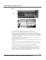
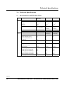
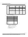
1
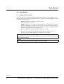
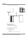
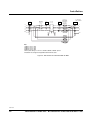
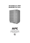
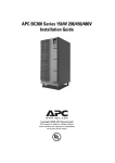
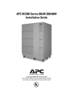
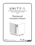
APC BC300 Series 10kW 208/450/480V
Installation Guide
Copyright ©2002 APC Denmark ApS
This manual is subject to change without
notice and does not represent a commitment
on the part of the vendor
Thank You
Thank you for choosing the APC BC300 Series. Read this Installation Guide before you install
and use the system as it provides important information on safe and efficient installation and
use.
The installation and use of this product must comply with national, federal, state, municipal
and local codes.
IMPORTANT SAFETY INSTRUCTIONS – SAVE THESE INSTRUCTIONS
Safety Symbols used in this manual
WARNING!
Indicates a hazard which, if not avoided, could result in injury or death.
CAUTION!
Indicates a hazard which, if not avoided, could result in damage to the product or
other property.
NOTICE!
Read and pay attention to this important information.
‘
WARNING
This UPS unit contains hazardous AC and DC voltages. Only qualified electricians should
connect the UPS, AC line and external batteries, and must be familiar with batteries and battery
installation.
Before installing, maintaining or servicing the UPS, shut off the UPS and disconnect all sources
of AC and DC power.
As the UPS has no built-in disconnection devices to switch off external AC and DC input power,
ensure that disconnection devices are available as separate parts in connection with the
installation.
The installer must provide each external disconnecting device for this UPS system with labels
with the following text:
“Isolate the Uninterruptible Power Supply (UPS) as instructed in this guide before working on
circuit”.
AC and/or DC voltage will always involve a potential risk of AC voltage at UPS output generated
from either batteries or utility. To avoid equipment damage or personal injury, always assume
that there may be voltage at UPS output.
This system is equipped with an auto-start function. If activated, the system may start without
warning. Refer to the “Programming” section for information on de-activation.
TEST BEFORE YOU TOUCH!
To reduce the risk of fire or electric shocks, install the UPS and external batteries in a
temperature and humidity controlled indoor area, free of conductive contaminants.
UPS batteries are high-current sources. Shorting battery terminals, DC terminals or DC busbars
can cause severe arcing, equipment damage and injury. A short circuit can cause a battery to
explode. Always wear protective clothing and eye protection and use insulated tools when
working on batteries.
CAUTION!
This unit contains components sensitive to electrostatic discharge (ESD). If you do not follow the
ESD procedures, you may cause severe damage to electronic components.
990-1378
2
Installation Guide APC BC300 Series 10kW 208/450/480V UPS
Contents:
1.0
2.0
3.0
Introduction
4
1.1
Tools and Equipment Needed
4
Receiving, Unpacking, Moving
and Storing the UPS and Batteries
5
2.1
2.2
5
5
Installation
3.1
3.1.1
3.2
3.2.1
3.2.2
3.2.3
3.3
3.3.1
3.3.2
3.3.3
3.3.4
3.3.5
3.3.6
3.4
3.5
3.5.1
3.5.2
3.5.3
3.5.4
3.5.5
3.5.6
3.6
3.6.1
3.6.2
4.0
5.0
6.0
7.0
8.0
Receiving, Unpacking and Moving to Site
Storing the UPS and Batteries
Requirements on Site
UPS Footprint (measurements in inches & mm)
Installing the Conduit Connection Kit
Conduit Connection Kit Contents
Installing Pedestals
Installing Conduit Box and Base Covers
Installing the Maintenance Bypass Panel and UPS
Component Overview (door open)
Wire Terminals
Wiring Diagram for BC300
Single Line Diagram for BC300
External Connection Board
Communication Interface Board (Option)
Smart Slot and Connection of Triple Chassis
APC BC300 Triple Chassis
Safety Warnings
Product Description
Installing Management Products
Powering the APC BC300 Triple Chassis
Troubleshooting
Product Specifications
Installation of External Batteries and Battery Breaker
Battery Installation
Battery Replacement
6
6
7
7
8
8
8
9
14
15
16
17
21
22
23
24
24
24
25
26
27
28
30
30
33
Initial Start-up and Phase Check
34
4.1
4.2
34
35
Initial Start-up and Phase Check (Internal Batteries)
Initial Start-up and Phase Check (External Batteries)
Clearing the Events Log
37
Start-up and Shutdown Procedure
38
6.1
6.2
38
39
Start-up from Maintenance Bypass
Shutdown Procedure
Technical Specifications
40
7.1
7.2
7.3
40
41
42
APC BC300 Series 10kW Technical Data
Battery Specifications
Dimensions/Weight
How to Contact APC
43
990-1378
Installation Guide APC BC300 Series 10kW 208/450/480V UPS
3
Introduction
1.0 Introduction
This Installation Guide provides information on UPS installation, wiring, start-up and shutdown procedures along with Maintenance Bypass Panel phase check and external battery
installation.
Electricians should always refer to national and local electrical codes prior to installing the
UPS system.
1.1
Tools and Equipment Needed
This section lists all tools and equipment required to connect the UPS to the Maintenance
Bypass Panel.
Insulated Tools and Other Equipment Needed:
• Torque wrench in inch-pounds or
newton-meters
• Standard U.S. and metric wrenches
• Petroleum jelly or conductive grease
• Brush (for applying petroleum jelly or
conductive grease to battery terminals)
• Mallet
• Volt-Ohm meter (True RMS - Digital)
• Pliers
• Ratchet and sockets
• Electrical tape
• Standard and Phillips screwdrivers
• Torx head screwdriver set
• APC BC300 User Guide
• Phase rotation meter
Cables and interconnection hardware not provided by APC.
990-1378
4
Installation Guide APC BC300 Series 10kW 208/450/480V UPS
Receiving, Unpacking, Moving and Storing the UPS and Batteries
2.0 Receiving, Unpacking, Moving and Storing the UPS and
Batteries
2.1
Receiving, Unpacking and Moving to Site
CAUTION!
Heavy equipment. To prevent personal injury or equipment damage, use caution when handling
and transporting UPS cabinet and equipment.
1. While the UPS system is still on the truck, inspect the equipment and shipping container(s)
for any signs of damage. Do not install the system if damage is apparent. If damage has
occurred, notify APC as soon as possible.
2. Compare the shipment with the bill of lading. Report any missing items to the carrier and
to APC immediately.
3. Remove the screws on the bottom part of the packaging side plates.
4. Remove the packing materials from the unit.
5. Verify compliance between type label on reverse side of UPS front door and system ordered.
Check input and output voltage.
6. Unbolt the unit from the pallet.
7. Remove the unit from the pallet with a forklift.
8. Use a forklift or hand truck to transport the unit to the installation or storage site. Study
the footprint to decide how to move the UPS through doorways and into position.
PLEASE RECYCLE
The shipping materials are recyclable. Please save for later use or dispose of them appropriately.
2.2
Storing the UPS and Batteries
Store the APC BC300 Series UPS between -4 and 104° F (-20 and 40° C). However, APC
recommends that the unit and batteries be stored between 59 and 77° F (15 and 25° C). This
temperature range, or cooler, allows batteries a longer shelf life. Recharge stored batteries
every 90 to 120 days.
See the section “Requirements on Site” in this Installation Guide for further details.
990-1378
Installation Guide APC BC300 Series 10kW 208/450/480V UPS
5
Installation
3.0 Installation
3.1
Requirements on Site
A 3-foot free space on all sides should be allowed during installation. Place the UPS in a clean,
dust-free environment, free of contaminants. Allow air circulation around the UPS cabinet and
any battery cabinets or racks.
• Ambient temperature range: 32 to 104° F (0 to 40° C).
Ideal temperature: 77° F (25° C)
NOTE: At 92° F (33° C), battery life would be approx. 50% compared to storage at a
normal temperature of 77° F (25° C). At 113° F (45° C). Battery life will be reduced
to some 25%. Make sure that the floor can support the weight of the UPS, external
batteries, and any other necessary equipment.
• Never install systems in direct sunlight or near heat sources.
• Service access from front and top of unit. Cable entry from bottom of unit.
• Do not operate the UPS or batteries in a sealed room or container.
NOTICE!
Allow a minimum clearance of 3 foot (914mm) for service in front of and above the UPS and 6
inches (152mm) at the back.
NOTICE!
Do not stand on the UPS. Keep the UPS cabinet surface free of objects.
990-1378
6
Installation Guide APC BC300 Series 10kW 208/450/480V UPS
Installation
3.1.1 UPS Footprint (measurements in inches & mm)
23.6
(600)
20.1
(510)
Conduit
Connection
Box
19.8 27.9 31.7
(504) (708) (804)
Cable Entry
Top View
Section A-A
View from inside cabinet, looking down
36.0
(914)
Minimum
Service
Clearance
36.0
(914)
Recommended
Cooling
Clearance
31.7
(804)
55.1
(1400)
A
A
Side View
Front View
Notes:
1. All dimensions are in inches (millimeters).
2. Minimum cooling and service clearance 36.00 (914).
3. Conduit entry is bottom of unit.
4. Unit weight = 1BPI 1111lbs (504kg) 2BPI 1331lbs (604kg).
5. Installation must comply with all applicable national and local codes.
Figure 1
3.2
Installing the Conduit Connection Kit
Insulated and other tools required
• 13 mm ratchet or wrench
• T20 torx screwdriver
• Greenly punch
• Equipment suitable for lifting heavy UPS off the ground
990-1378
Installation Guide APC BC300 Series 10kW 208/450/480V UPS
7
Installation
3.2.1 Conduit Connection Kit Contents
For Pedestals:
• 23 pedestals
• 4 M8 x 100 mm bolts
• 4 M8 lock washers
• 4 M8 flat washers
• 4 M8 nuts
For Conduit Box:
• 1 Conduit Box
• 1 Conduit Box Cover
• 11 M5 x 12 mm T20 Torx screws
• 11 M5 lock washers
• 11 M5 flat washers
For Base Covers:
• 2 Side Base Covers
• 2 Front/Rear Base Covers
• Hook and loop fasteners
3.2.2 Installing Pedestals
CAUTION!
Heavy Equipment. Use caution and appropriate equipment to safely lift the UPS several inches
above the floor when installing pedestals.
1) Remove brackets mounted to the UPS feet during shipping
2) Lift the UPS off the floor and place the pedestals under UPS feet where the holes of
pedestals and holes in UPS feet are aligned
3) With caution lower the UPS feet into pedestal
4) Fasten but DO NOT TIGHTEN bolts, washers and nuts on the four corner feet of UPS
NOTICE!
Place flat washer under the bolt head and the lock washer under the nut.
5) Move the UPS to the installation site
Tighten the bolts
3.2.3 Installing Conduit Box and Base Covers
1) Punch conduit holes in the back of the conduit box
2) Place the conduit box between the center leg and right leg of the unit, with the open side
facing the front of the unit
990-1378
8
Installation Guide APC BC300 Series 10kW 208/450/480V UPS
Installation
3) Use four T20 torx screws and washers to fasten the conduit box to the front legs of the UPS
NOTICE!
Place flat washer, lock washer and screw in this particular order.
4) After all UPS wiring has been completed, attach conduit box cover to the front of the conduit
box
5) Use hook and loop fasteners to attach the base covers to the UPS
3.3
Installing the Maintenance Bypass Panel and UPS
IMPORTANT!
If you do not have an APC Maintenance Bypass Panel, you must provide overcurrent protection
and a UPS input AC disconnect means.
APC strongly recommends that a means of bypassing the UPS from the critical load be
provided for maintenance.
Follow these guidelines when installing the Maintenance Bypass Panel and UPS:
• Install the Maintenance Bypass Panel within sight of the UPS. When installing the
Maintenance Bypass Panel, see illustrations under Wiring Diagram for BC300 and
any instructions provided with the Maintenance Bypass Panel.
• Install all wiring in accordance with applicable electrical codes. Use 75° C copper
conductors.
• Install the AC input and UPS output in separate conduits. UPS output circuits
must be installed in dedicated conduit systems and separate from other
electrical circuits.
• Control wiring must be installed in a separate conduit.
• Good ground connections are necessary to reduce electrical noise and make the
operation of the UPS and the loads safe. Follow the grounding guidelines in the
installation wiring diagram. Refer to the National Electrical Code (NEC),
appropriate IEEE documents, and all applicable codes.
• For systems with non-linear, neutral-connected loads, standard practice is to size the
neutral conductor for 1.732 times the phase current.
• When installing the AC wiring, refer to the illustration Single Line Diagram for
BC300 and to any additional diagrams provided with the UPS. The illustration
shows typical installations. Your installation may be different.
• See Component Overview illustration for a view of the UPS with covers removed. See
Wiring Termination or Component Overview illustrations for UPS wiring
terminations. Refer to illustration External Connection Board for information on the
external connection board. See illustration Communication Interface Board (Option)
for information on the optional communication interface board.
If you have any questions, contact APC Technical Support for assistance.
990-1378
Installation Guide APC BC300 Series 10kW 208/450/480V UPS
9
Installation
Maintenance
Bypass Switch
AC Line
Input
L1
UPS Input
Disc. Switch
Shown in Open
Position
L3
F4
1
F6
AC Output
from UPS
Uninterruptible
Power Supply
F1
L1
2
F5
L2
AC Input
to UPS
L1
4
L1
4
5
6
U
L2
L2
L3
L3
8
U
7
12
U
11
GRD
16
U
15
L1
U
19
L2
L3
N
20
G
L1
L3
N
N G N
N
AC Output
to Critical Load
L2
F3
L3
TO CRITICAL
LOAD CENTER
3
F2
L2
3
Contacts marked "U"
closed in "UPS".
Contacts marked "BP"
closed in Bypass.
Contacts are Make
before Break.
G
N
G
GRD
2
BP 1
6
BP 5
10
BP 9
14
BP 13
18
BP 17
Notes:
1. 208V F1, F2, F3 = 35A
2. 480V F1, F2, F3 = 15A
3. 208V F4, F5, F6 = 45A
4. 480V F4, F5, F6 = 20A
5. All AC power cabling is 3- or 4-wire + Ground at 208VAC / 480VAC 3-phase.
6. Installation must comply with all applicable national and local codes.
Figure 2 - SBP Electrical Schematic 208V & 480V
990-1378
10
Installation Guide APC BC300 Series 10kW 208/450/480V UPS
Installation
Relay
"UPS in Static Bypass" Ind. Light
G
R
UPS Input
Disconnect
Switch
UPS Maintenance
Bypass Switch
UPS Bypass
14
13
1
9
"UPS in Maintenance Bypass" Ind. Light
R
On-Off
1 BYP 2
1
2
3 UPS 4
3
4
5 BYP 6
5
6
7 UPS 8
9 BYP 10
11 UPS 12
13 BYP 14
Keyed Solenoid Lock Release Switch
15 UPS 16
17 BYP 18
Lock
Release
19 UPS 20
1 BYP 2
3 BYP 4
13
14 0X
22
21 X0
5 BYP 6
7 UPS 8
F1-F2-F3
F1A
1A
H1 H3
X1
1
G
L1
L2
L3
G
L1
L2
32 X0
43
44 0X
F4-F5-F6
440, 450, 480
VAC Primary
AC Output
to Critical Load
31
L3
AC Output from UPS
G
L1
L2
L3
AC Line Input
G
L1
L2
2
3
4
5
C
N
N
D
C
6
L3
AC Input to UPS
H2
N
120 VAC
440, 450, 480
VAC Primary
H4
H1
X2
X1
120 VAC
Secondary
XFMR 1
H3
H2
120 VAC
Secondary
XFMR 2
X
H4
Solenoid Lock
Mechanism
(Energize to Unlock)
+
-
120 VDC
X2
5A
Auxiliary Switch Circuit
Notes:
1. F1, F2, F3 = 15A
2. F4, F5, F6 = 25A
3. All AC power cabling is 3 wire + Ground at 450VAC 3-phase.
4. Installation must comply with all applicable national and local codes.
Figure 3 - SBP Electrical Schematic 450V
990-1378
Installation Guide APC BC300 Series 10kW 208/450/480V UPS
11
Installation
L1 L2 L3 N
G
L1 L2 L3 N
AC Output to
Critical Load
G
AC Output
from UPS
L1 L1 L2 L2 L3 L3
N
N
G
AC Line Input
L1 L2 L3
AC Input
to UPS
UPS Con NC
AUX Switch
20.00
(508)
16.00
(406)
Mounting Dimension
Padlock
10.00
(254)
5.75
(146) 10.50
(267)
Switches Mounted at
Both Ends for Stability
21.00
20.00
(533)
(508)
Mounting Dimension
All Inputs and Outputs to Terminals
Terminal Blocks
Mounted on Hi Hat
Removable
Bottom Plate
Notes:
1. All dimensions are in inches (millimeters)
2. Minimum cooling and service clearance 36.00 (914) from front of unit.
3. Installation must comply with all applicable national and local codes.
Figure 4 - SBP Electromechanical 10kW 208V and 480V
990-1378
12
Installation Guide APC BC300 Series 10kW 208/450/480V UPS
Installation
L1 L2 L3 N
G
AC Output to
Critical Load
L1 L2 L3 N
L1 L1 L2 L2 L3 L3
G
AC Output
from UPS
N
AC Line Input
N
G
L1 L2 L3
AC Input
to UPS
UPS Con NC
AUX Switch
24.00
(610)
2.00
(51)
20.00
(508)
Mounting Dimension
24.00
25.00
(610)
(635)
Mounting Dimension Lock Release
12.00
(305)
Fuses/Locks are
Under Hi Hat
4.00
(102)
3.00
(76)
4’’ Tall Hi Hat
With Terminals
Backpanel 22’’ Square
Removable
Bottom Plate
Notes:
1. All dimensions are in inches (millimeters)
2. Minimum cooling and service clearance 36.00 (914) from front of unit.
3. Installation must comply with all applicable national and local codes.
Figure 5 - SBP Electromechanical 10kW 450V
990-1378
Installation Guide APC BC300 Series 10kW 208/450/480V UPS
13
Installation
3.3.1 Component Overview (door open)
DC fuse
F001-F003
AC fuse
F007-F009
Display unit
ON/OFF
buttons
Controller
Board
Communication
Interface
Utility RFI/
Fuse Board
Input/Output
Terminal
Blocks
Battery
Connection
Figure 6 Component Overview
990-1378
14
Installation Guide APC BC300 Series 10kW 208/450/480V UPS
Installation
3.3.2 Wire Terminals
Battery X003
Utility input
X001
AC Output
X004
Grounding Terminals
Figure 7 Wire Terminals
990-1378
Installation Guide APC BC300 Series 10kW 208/450/480V UPS
15
Installation
3.3.3 Wiring Diagram for BC300
System input
3- or 4-wire + ground
L1 L2 L3 N G
System output
3- or 4-wire + ground
Maintenance Bypass Panel
L1 L2 L3 N G
X001
X004
Utility
output
Utility
input 1
X002
UPS AUX
L1 L2 L3 N G
1 2 3
L1 L2 L3 N G
X001
1 2 3
X009
X003
L1 L2 L3 N G
External
Connection
Board
L1 L2 L3 N G E
X004
Grounding
Electrode
X0012
1 2 3 4 5 6 7 8 11 12 13 14 15 16 17
UPS
Figure 8 Wiring Diagram for BC300
Notes:
1. All systems are installed as 3-wire + ground.
2. Cables not provided by APC.
3. All AC power cables must be 3- or 4-wire plus ground 3-phase
4. Power and data cabling must be run in separate conduits.
5. Installation must comply with national and local codes.
NOTICE!
You must provide overcurrent protection and UPS input AC disconnect means.
Refer to “Technical Specifications” section in this Installation Guide for recommended UPS input
and output overcurrent protection.
CAUTION!
UPS systems can be connected as 3-phase, 3-wire plus ground, if no loads are using the neutral
conductor.
CAUTION!
Read warnings on page 2 of this Installation Guide before continuing.
NOTICE!
Only authorized electricians may install the UPS and all applicable codes must be observed.
990-1378
16
Installation Guide APC BC300 Series 10kW 208/450/480V UPS
Installation
NOTICE!
Always keep AC, DC and communication cables separated.
NOTICE!
The grounding electrode conductor (Protective Earth - PE) must be the same size (ampacity) as
the UPS input circuit conductors. Conduit is not an acceptable grounding electrode conductor see National Electrical Code Section 250-91(a).
NOTICE!
The unit is wired from the factory as a separately derived system. Output neutral is bonded to
equipment ground through main bonding jumper inside the UPS. See National Electrical Code
Article 250-5(d) and 250-26 for correct installation grounding.
3.3.4 Single Line Diagram for BC300
Utility Source (Provided by Others)
208V 3 or 4 Wire + Ground
MIB
50A.T.
37A
Service
Bypass
Panel
F4, 5, 6
UIF
Q001
UIS
37A
28A
UPS
28A
F1, 2, 3
UOF
Q003
BS
Q002
UOS
28A
Notes:
1. Must be 3- or 4-wire + Ground provided
WYE-source.
2. Interconnecting power cabling is provided
by others.
3. Input overcurrent protection is based on
80% rating - any deviation, please contact
APC.
4. F1, F2, F3 = 35A
5. F4, F5, F6 = 45A
6. All AC power cabling is 3- or 4-wire +
Ground at 208VAC 3-phase.
7. UPS output cables and input cables must be
in separate conduits.
8. Power wiring and control wiring must be in
separate conduits.
9. See installation manual for battery
information.
10. Installation must comply with all applicable
national and local codes.
UPS System Output
10kW
208V 3 or 4 Wire & Ground
Figure 9 Single Line Diagram for BC300 208V
990-1378
Installation Guide APC BC300 Series 10kW 208/450/480V UPS
17
Installation
Utility Source (Provided by Others)
450V 3 Wire + Ground
MIB
25A.T.
17A
Service
Bypass
Panel
F4, 5, 6
UIF
Q001
UIS
13A
17A
UPS
13A
F1, 2, 3
UOF
Q002
UOS
Q003
BS
Notes:
1. Must be 3 wire + Ground
2. Must be 3 wire + Ground cabling
provided by others.
3. Input overcurrent protection is based on
80% rating - any deviation, please contact
APC.
4. F1, F2, F3 = 15A
5. F4, F5, F6 = 25A
6. All AC power cabling is 3 wire + Ground
at 208VAC 3-phase.
7. UPS output cables and input cables must
be in separate conduits.
8. Power wiring and control wiring must be
in separate conduits.
9. See installation manual for battery
information.
10. Installation must comply with all
applicable national and local codes.
13A
UPS System Output
10kW
450V 3 Wire & Ground
Figure 10 Wiring Line Diagram for BC300 450V
990-1378
18
Installation Guide APC BC300 Series 10kW 208/450/480V UPS
Installation
Utility Source (Provided by Others)
480V 3 or 4 Wire + Ground
MIB
25A.T.
16A
F4, 5, 6
UIF
Service
Bypass
Panel
Q001
UIS
16A
12A
UPS
12A
F1, 2, 3
UOF
Q002
UOS
Q003
BS
12A
Notes:
1. Must be 3- or 4-wire + Ground
2. Must be 3- or 4-wire + Ground cabling
provided by others.
3. Input overcurrent protection is based on
80% rating - any deviation, please contact
APC.
4. F1, F2, F3 = 15A
5. F4, F5, F6 = 25A
6. All AC power cabling is 3- or 4-wire +
Ground at 480VAC 3-phase.
7. UPS output cables and input cables must
be in separate conduits.
8. Power wiring and control wiring must be in
separate conduits.
9. See installation manual for battery
information.
10. Installation must comply with all
applicable national and local codes.
UPS System Output
10kW
480V 3 or 4 Wire & Ground
Figure 11 Wiring Line Diagram for BC300 480V
NOTICE!
Size utility input overcurrent protection device as per applicable codes. See below table for utility
input voltage and current ratings.
990-1378
Installation Guide APC BC300 Series 10kW 208/450/480V UPS
19
Installation
UPS Model
Input
Current
Output
Current
Recommended
MIB
DC Voltage
DC Current
10kW 208V
37A
28A
50AT
216V
50A
10kW 450V
17A
13A
25AT
216V
50A
10kW 480V
16A
12A
25AT
216V
50A
Notes:
1. 3- or 4-wire provided source.
2. Cables not provided by APC.
3. Recommended input over current protection (MIB) based on an 80% rated device.
4. All AC cables must be AC 3- or 4-wire 3-phase.
5. Keep UPS input, output and control cables in separate conduits.
6. Installation must comply with all applicable national and local codes.
NOTICE!
You must provide overcurrent protection and UPS input AC disconnect means.
See the “Technical Specifications” section in this Installation Guide for recommended UPS input
and output overcurrent protection.
CAUTION!
UPS systems can be connected as 3-phase, a 3-wire plus ground, provided that the load is not
connected to the neutral conductor.
NOTICE!
Only authorized electricians may install the UPS and all applicable codes must be observed.
NOTICE!
Always keep AC, DC and communication cables separated.
NOTICE!
The grounding electrode conductor (Protective Earth - PE) must be the same size (ampacity) as
the UPS input circuit conductors. Conduit is not an acceptable grounding electrode conductor see National Electrical Code Section 250-91(a).
NOTICE!
The unit is wired from the factory as a separately derived system. Output neutral is bonded to
equipment ground through main bonding jumper inside the UPS. See National Electrical Code
Article 250-5(d) and 250-26 for correct installation grounding.
NOTICE!
The maintenance bypass switch must be a 4-pole device switching all three phases and neutral.
If you are using a 3-pole device, contact APC Technical Support for instructions on how to
convert the unit to a not-separately derived system.
990-1378
20
Installation Guide APC BC300 Series 10kW 208/450/480V UPS
Installation
3.3.5 External Connection Board
Use Class 1 wiring methods.
Figure 12 External Connection Board
990-1378
Installation Guide APC BC300 Series 10kW 208/450/480V UPS
21
Installation
3.3.6 Communication Interface Board (Option)
Use Class 1 wiring methods.
X002
X001
X003 25 PIN SUB D MALE
X004 25 PIN SUB D MALE
Communication
Interface Board
X005
X004
X005 25 PIN SUB D FEMALE
X003
Serial Port
RS232
Serial Port
0-20 mA current loop
Relay Contacts: 30VAC, 60 VDC
Maximum 0.5 A, minimum 0.05 mA
14
15
2
"UPS on" (shown with UPS off)
16
17
4
"Static bypass operation" (shown with static bypass operation off)
18
19
6
"Battery operation" (shown with battery operation off)
20
21
8
"Battery low warning" (shown with "battery low" warning off)
13 +
25 –
Remote UPS shut down input (3.5 - 25 VDC pulse for 1 second minimum)
Figure 13 Communication Interface Board
990-1378
22
Installation Guide APC BC300 Series 10kW 208/450/480V UPS
Installation
3.4
Smart Slot and Connection of Triple Chassis
Connect the Triple Chassis to the serial ports on the Communication Interface Board, and to
the 24V supply (power supply included). Terminal locations shown below.
Serial ports
Figure14 Communication Interface
990-1378
Installation Guide APC BC300 Series 10kW 208/450/480V UPS
23
Installation
3.5
APC BC300 Triple Chassis
Figure 15Triple Chassis
The APC BC300 Triple Chassis is an American Power Conversion (APC) external management
product that allows you to use monitoring and control management products with your APC
BC300 series UPS.
3.5.1 Safety Warnings
Use the APC BC300 Triple Chassis only with an APC BC300 UPS.
Do not connect a computer to any APC BC300 Triple Chassis port using a straight-through
extension cable. Use the communications cable provided with the APC BC300 Triple Chassis.
Connections using a cable made by any other manufacturer may cause damage or improper
operation of the APC BC300 Triple Chassis, the UPS, or the computer.
3.5.2 Product Description
➊
➍
➋
➌
1 Monitoring port
3 Status LED
2 To UPS port
4 Optional power port
3.5.2.1 Monitoring Port
The Monitoring port has two functions:
• Connecting to a terminal for configuration of the chassis. For direct connection to the
Monitoring port, you must use the monitoring cable supplied with the chassis.
990-1378
24
Installation Guide APC BC300 Series 10kW 208/450/480V UPS
Installation
• Connecting to other APC external management products in a cascade series.
3.5.2.2 To UPS Port
The “To UPS” port connects the chassis to the UPS, using the BC300 UPS cable. The cable
connector plugs into a communications port on an APC BC300 UPS.
3.5.2.3 LEDs
IF the LED is…
THEN the Silcon Triple Chassis…
off
is not receiving power.
flashing quickly
(5 times per second)
has not been configured. See the Web/SNMP Management Card
Installation Guide on the CD for more information.
flashing slowly
(1 time per second)
is powered on but is not communicating with the UPS.
on
is operating normally.
3.5.2.4 Power Input
With the power input, you can power the APC BC300 Triple Chassis from an external source,
using the 24 VDC power adapter.
3.5.3 Installing Management Products
There are two basic types of APC management products that work with the APC BC300 Triple
Chassis:
• Management cards, which fit into external management products that are equipped
with a card slot.
• External management products, which connect to the monitoring (or advanced) port
of other external management products.
NOTICE!
The name “Monitoring” port varies from product to product, but its purpose is the same.
3.5.3.1 Order of Management Cards
Because UPS signals are passed between management products, you must install management
cards in the correct order for them to work together properly. The card slots are numbered 1 to
3, from left to right, as viewed from the rear of the chassis. The following table lists the
management cards, their priority, and proper position.
Management Card
Priority
Web/SNMP Management Card
Highest
Out-of-Band Management
Card
Second-highest
Interface Expander
Second lowest
Environmental Monitoring
Card
Lowest
Position
High-numbered slot
Low-numbered slot
3.5.3.2 Installing Management Cards
To install management cards, perform the following steps.
990-1378
Installation Guide APC BC300 Series 10kW 208/450/480V UPS
25
Installation
1) Make sure that the chassis is powered off.
2) Install management cards into the housings on the rear of the chassis. See the instructions
supplied with the cards and the table above.
3) If you are cascading other APC external management products to the APC BC300 Triple
Chassis: Connect the UPS cable (supplied with the management card) to the monitoring
port of the chassis and to the “To UPS” port of the other management products (Share-UPS,
MasterSwitch, etc.). See “Cascading setup of the APC BC300 Triple Chassis”.
4) Power the APC BC300 Triple Chassis and all external management cards.
NOTICE!
If your configuration requires additional power, connect a 24V AC/DC power adapter available
from APC for all models of Triple Chassis.
3.5.3.3 Cascading setup of the APC BC300 Triple Chassis
If you need more than the three card slots available with the APC BC300 Triple Chassis, or if
you want to use other external management products, you can connect management products
in a cascade series, provided that the total amperage of all installed management products —
cards and external — does not exceed the supplied amperage. (See “Determining Power
Requirements”).
NOTICE!
When cascading Triple Chassis units, you may need to use a power adapter.
To add card slots, you can cascade the APC BC300 Triple Chassis with the standard Triple
Chassis management product, installing the APC BC300 Triple Chassis closer to the UPS.
3.5.4 Powering the APC BC300 Triple Chassis
The APC BC300 Triple Chassis supplies power to the installed management cards and to the
Monitoring port, allowing you to power multiple management products.
3.5.4.1 Power Considerations
If the total current required by all the installed management products exceeds 500 mA, you
must use a 24 VDC power adapter. To find out whether you need additional power see
“Determining power requirements”.
3.5.4.2 Power Adapters
APC offers two different 24 VDC power adapters.
• The standard adapter can provide an additional 400 mA.
• The universal adapter can provide 850 mA.
3.5.4.3 Using a Power Adapter
Plug the adaptor into a protected power outlet and into the Optional Power port of the APC
BC300 Triple Chassis.
NOTICE!
If the power adapter loses power because of a UPS shutdown, its attached management products
may not operate properly, thus adversely affecting the UPS and its protected equipment.
990-1378
26
Installation Guide APC BC300 Series 10kW 208/450/480V UPS
Installation
3.5.4.4 Triple Chassis Power Considerations
The Triple Chassis receives its power from the UPS through the supplied 24 VDC universal
adapter. The total current required by your management products must not exceed the 850 mA
limit of the power adapter. See “Determining power requirements”.
3.5.4.5 Determining Power Requirements
To determine the total amount of current required by your management products, add the
individual current requirements for each management product to be installed with the APC
BC300 Triple Chassis to the current requirements of the chassis itself.
Management Product
Draw (mA)
Share-UPS 8-port Interface Expander
65
Expansion Chassis
30
Triple Chassis
20
APC BC300 Triple Chassis
90
Web/SNMP Management Card
110
Interface Expander
45
Out-of-Band Management Card
35
Environmental Monitoring Card
60
Isolated Extension Cable
50
Remote Power-Off Device
35
3.5.5 Troubleshooting
The following table shows the solutions to common problems with the operation of the Triple
Chassis
Problem
Possible Cause
Solution
Status LED is off
The chassis is not
receiving adequate
power.
See “Powering the APC BC300
Triple Chassis”, and verify that you
are not exceeding current
requirements.
Status LED is flashing
quickly
The chassis has not been
configured.
Configure the Silcon Triple Chassis.
See the Web/SNMP Management
Card Installation Guide on the CD
for more information.
Status LED is flashing
slowly
The chassis is not
communicating with the
UPS.
Verify that the supplied UPS cable is
properly connected to the Triple
Chassis and to a communications
port on the UPS.
Attached management
product cannot identify
UPS model or nominal
output voltage.
The management
firmware does not
support 3-phase UPSs.
You may be able to upgrade the
firmware of the management
product. Call APC Customer
Support.
3.5.5.1 If Problems Persist
For problems not covered in the troubleshooting chart or for persistent problems, follow this
procedure:
990-1378
Installation Guide APC BC300 Series 10kW 208/450/480V UPS
27
Installation
1) Note the serial number and date of purchase of the APC BC300 Triple Chassis. Contact
APC Customer Support at the phone number or address listed in How to Contact APC
section of this manual.
2) Be prepared to provide a description of the problem. A technician will help solve the
problem over the phone, if possible, or will give you a return material authorization (RMA)
number.
3) If the APC BC300 Triple Chassis is under warranty, repairs are free of charge. If the
warranty has expired, there will be a nominal charge for repair.
4) Pack the APC BC300 Triple Chassis carefully in its original packaging, if possible. Do not
use polystyrene beads for packing. Damage sustained in transit is not covered under the
warranty. Enclose a letter in the package with your name, address, RMA number, a copy of
the sales receipt, daytime phone number, and payment (if applicable).
5) Mark the RMA number clearly on the outside of the shipping carton. The factory will not
accept any materials without this marking.
6) Return the Triple Chassis by insured, prepaid carrier to the address given to you by APC
Customer Support.
3.5.6 Product Specifications
3.5.6.1 Monitoring Port Pin Assignments
The Monitoring port is a 9-pin communications port. The port operates with no flow control at
a rate of 2400 baud. The data format is 8 data bits with 1 start bit, 1 stop bit, and no parity.
When the Triple Chassis operates with simple signalling, the following limitations and
capabilities apply to the Monitoring port:
• Pins 3, 5, and 6 are open collector outputs which must be pulled up to a common
referenced supply no greater than +40 VDC. The transistors are capable of a noninductive load of 25 mA. Use only Pin 4 as the common.
• The output at Pin 2 generates a low-to-high RS-232 level when the device is
signalling an On Battery condition. The pin is normally at a low RS-232 level.
• The UPS is signalled to shut down when a high RS-232 level is applied to Pin 1 for
4.5 seconds. Shutdown is also dependent on the UPS status.
When the Triple Chassis operates with advanced signaling, the following limitations and
capabilities apply to the Monitoring port:
• Pin 7 is unassigned.
• DC operating voltage is available on Pin 8. This voltage may be from the UPS or from
an external adapter.
990-1378
28
Installation Guide APC BC300 Series 10kW 208/450/480V UPS
Installation
Normally Open
Line Fail Signal
Normally Open
Low Battery Signal
Normally Closed
Line Fail Signal
Common
UPS Shut Down RS-232 Input or
Advanced Mode RS-232 Data RX In
Line Fail RS-232 Output or
Advanced Mode RS-232 Data TX Out
Unregulated
+24 VDC Output
Chassis
Figure 16 Monitoring Port Pin Assignment
990-1378
Installation Guide APC BC300 Series 10kW 208/450/480V UPS
29
Installation
3.5.6.2 Power, Physical, and Environmental Specifications.
Item
Specification
Power
Turn on voltage:
> 22 VDC
Turn off voltage:
< 16 VDC
Current draw (normal operation):
90 mADC
Current draw (voltage < 16 VDC):
< 1 mADC
Physical
Size (H xW x D):
44 x 432 x 127 mm (1.75 x 17.0 x 5.0 in)
Weight:
1.81 kg (4.02 lb)
Shipping weight:
3.65 kg (8.12 lb)
Environmental
Elevation (above MSL):
- Operating
- Storage
0 to 3000 m (0 to 10,000 ft)
0 to 15 000 m (0 to 50,000 ft)
Temperature:
- Operating
- Storage
0 to 45˚C (32 to 113˚F )
-20 to 70˚C (-4 to 158˚F)
Relative humidity:
- Operating
- Storage
0 to 95%, non-condensing
0 to 95%, non-condensing
Electromagnetic immunity:
3.6
FCC Class A
EN50082-1 verified
Installation of External Batteries and Battery Breaker
Some units are connected to optional external batteries in a separate cabinet or rack.
External batteries must be installed and connected to the UPS by an authorized service person
familiar with UPS battery installations and applicable building and electrical codes.
3.6.1 Battery Installation
WARNING
Full voltage and current are always present at the battery terminals. The batteries used in this
system can produce dangerous voltages, extremely high currents, and may cause a risk of
electric shock. They may cause severe injury if the terminals are shorted together or to ground
(earth). You must be extremely careful to avoid electric shock and burns caused by contacting
battery terminals or shorting terminals during battery installation. Do not touch uninsulated
battery terminals.
Only authorized service personnel familiar with battery systems and required precautions may
install and service the batteries. The installation must conform to national and local codes. Keep
unauthorized personnel away from batteries.
990-1378
30
Installation Guide APC BC300 Series 10kW 208/450/480V UPS
Installation
CAUTION!
The qualified service person must take these precautions:
1. Wear protective clothing, such as rubber gloves and boots and protective eye wear. Batteries
contain caustic acids and toxic materials and can rupture or leak if mistreated. Remove rings,
metal wristwatches, other metal objects and jewellery. Do not carry metal objects in your
pockets where the objects can fall into the battery cabinet.
2. Tools must have insulated handles and must be insulated so that they will not short battery
terminals. Do not allow a tool to short between individual or separate battery terminals or to
the cabinet or rack. Do not lay tools or metal parts on top of the batteries, and do not lay them
where they could fall onto the batteries or into the cabinet.
3. Install the batteries as shown on the drawing provided with the batteries. When connecting
cables, never allow a cable to short across a battery’s terminals, the string of batteries, or to
the cabinet or rack.
4. Align the cables on the battery terminals so that the cable lug will not contact any part of the
cabinet or rack, even if the battery is moved. Keep the cable away from any sharp metal
edges.
5. Install the battery cables so they cannot be pinched be the UPS or battery cabinet doors.
6. Do not connect the battery terminal to ground (earth). If any battery terminal is inadvertently
grounded, remove the source of the ground. Contacting any part of a grounded battery can
cause a risk of electric shock.
7. To reduce the risk of fire or electric shock, install the batteries in a temperature and humidity
controlled indoor area, free of conductive contaminants.
8. Battery system chassis ground (earth) must be connected to the UPS chassis ground (earth).
If you use conduit, this ground conductor must be routed in the same conduit as the battery
conductors.
9. Where conductors may be exposed to physical damage, protect the conductors in accordance
with all applicable codes.
10. If you are replacing batteries or repairing battery connections, shut off the UPS and remove
both AC and DC power.
Battery Installation Guidelines:
• Refer to any instructions provided with the batteries, battery breaker and pre-charge
/discharge switch.
• External batteries require a fused disconnect or a DC battery breaker. There should
be a disconnecting means for each battery string. The external battery fuse protects
the battery cables. Size the cables based on the overcurrent protection device.
• The battery cables must be sized for a total maximum voltage drop of 2.0 VDC at the
rated DC current.
• Wherever conductors may be exposed to physical damage, protect the conductors in
accordance with any applicable codes. This includes battery cables between the UPS
and the battery system and cables between battery cabinets or racks.
• APC recommends the routing of battery cables through flexible conduits. Install
flexible conduits for battery cables according to local or national codes.
• The battery system ground (earth) must be connected to the UPS chassis ground
(earth). This ground conductor must be routed with the battery cables.
990-1378
Installation Guide APC BC300 Series 10kW 208/450/480V UPS
31
Installation
• Clean cables and battery terminals before making the battery connections. Apply a
thin coating of conductive grease before making the battery connections, or, after
connection, apply petroleum jelly to the entire connection.
• Torque battery connections to the battery manufacturer’s specifications.
Follow below battery system guidelines and any instructions shipped with the
battery system:
1. Verify that the DC fuses are removed from the UPS. See Component Overview illustration
for the location of the DC fuse holder.
2. Install the ground conductor. See Wiring Termination illustration for the location of the
grounding electrode terminals in the UPS.
3. Connect the cables between batteries.
a. In each battery string, connect the cables between batteries as shown in the battery
installation diagram provided with the batteries.
b. Meter the positive (+) and negative (-) terminal on each battery string to verify proper
nominal voltage and polarity.
4. Connect the battery cables between battery strings.
a. Connect the negative (-) cables between battery strings as shown in the battery
installation diagram provided with the batteries.
b. Meter the DC voltage between the positive terminals of the strings. The voltage should
measure less than 5 volts. If it exceeds 5 volts, correct any wiring errors
before you continue.
c. Connect the positive (+) cables between battery strings as shown in the battery
installation diagram provided with the batteries.
5. Install the battery breaker and pre-charge / discharge switch. Refer to
any instructions provided with the battery breaker and pre-charge / discharge switch.
6. Connect the external batteries to the UPS.
a. Connect the positive (+) cable(s) to the UPS first. Install ring connectors for 8 mm
(approx. 5/16”) bolts as required.
b. To prevent short circuits, insulate the UPS end of the negative (-) cable(s).
CAUTION!
Do not connect the negative (–) cables to the UPS yet.
c.
Connect the positive (+) cable(s) to the battery system and tighten to the proper torque
specifications.
d. Connect the negative (S) cable(s) to the battery system and tighten to the proper
torque specifications.
7. Check the DC voltage.
a. Connect the DC fuse(s) as shown in the battery installation diagram provided with the
batteries. Verify proper voltage (216 VDC) and polarity at the battery pack.
b. Set the battery breaker to “ON”.
c. Meter for proper nominal DC voltage at the UPS end of the cables. Make sure the
polarity agrees with the markings on the UPS battery input terminals.
d. After checking the DC voltage, set the battery breaker to “OFF”.
8. Connect the negative (-) cable(s) to the UPS. Tighten to the proper torque specifications.
9. Replace all covers.
10. Continue with the “Initial Start-up and Phase Check” section in this Installation Guide.
990-1378
32
Installation Guide APC BC300 Series 10kW 208/450/480V UPS
Installation
3.6.2 Battery Replacement
Only authorized service personnel familiar with battery systems may replace batteries. See the
“Start-up & Shutdown Procedure” section in this Installation Guide to bypass and shut down
the UPS.
CAUTION!
Study all warnings at the beginning of this section before replacing the batteries.
• Use the Same Number and Type of Battery: To ensure a well-functioning UPS
and to maintain proper battery charger operation, you must replace a given number
of batteries with the same number of batteries. The batteries must be the same
manufacturer type as the original batteries and have the same voltage and amperehour rating as the original batteries.
• Verify that the Battery Terminal is not Grounded: If any battery terminal is
inadvertently grounded, you must remove the connection from the terminal to
ground (earth) before you service the batteries. Contacting any part of a grounded
battery can cause a risk of electric shock. To reduce the risk of electric shocks,
disconnect the ground connection before you service the batteries.
• Handle Used Batteries with Care: Assume that old batteries are fully charged.
Use the same precautions you would use when handling a new battery. Do not short
battery terminals or the battery string with a cable or tool when you disconnect the
batteries.
• Dispose of Batteries Properly: Do not dispose of batteries in a fire as the batteries
may explode. Do not open or mutilate batteries. Released electrolyte is harmful to
the skin and eyes and may be toxic. Batteries contain lead. Many state and local
governments have regulations about disposing of used batteries. For assistance, call
APC Technical Support or call your local APC office.
990-1378
Installation Guide APC BC300 Series 10kW 208/450/480V UPS
33
Initial Start-up and Phase Check
4.0 Initial Start-up and Phase Check
After installing the unit, use this section to perform the initial start-up and the phase check for
the Maintenance Bypass Panel.
4.1
Initial Start-up and Phase Check (Internal Batteries)
This section is applicable for INITIAL STARTUP of an APC Silcon BC Series UPS with APC
Supplied Maintenance Bypass Panel ONLY.
WARNING
Some units have been programmed at the factory for “autostart”. If programmed for “autostart”,
the unit will turn on when utility (AC line) is applied (after a 60-second delay). For more
information or to change this feature, see the User Guide.
Before continuing, read the warnings on page 2 of this Installation Guide.
CAUTION!
No load should be connected when this procedure is carried out.
1. Make sure that all AC and DC power is off.
2. Set the UPS bypass switch to “UPS”.
3. Make sure that the main circuit breaker in the load panel is off so that the loads cannot
receive power from the UPS.
4. Open the UPS front door(s).
5. Remove the retaining brackets for the fuse holder containing DC fuses F001, F002, and
F003. See Component Overview illustration in this Installation Guide for location of fuse
holder.
6. At the utility input, switch on the input power to the Maintenance Bypass Panel.
7. At the Maintenance Bypass Panel, set the UPS AC disconnect switch to “ON”. The UPS
display should show “System type xxkVA xxxV”.
8. Within 20 seconds, the display should show **Stand-by** and an audible alarm should
sound.
9. Check the phase rotation at the service panel and the unit. The unit will not start if the
phase rotation is incorrect. The phase rotation must be A, B, C and clockwise.
10. When the audible alarm stops, press the green “ON” button located inside the UPS front
door. The display should show “Normal operation load power xx%”.
NOTICE!
One or more alarms may occur. If the alarm(s) persists for more than 20 seconds, refer to the
“Alarms” section of the User Guide. If the unit activates a “battery monitor alarm”, you should set
the user parameter “battery monitor reset” to “ON”
11. Open DC fuse holder (F001, F002, F003). For location of DC fuse holder, see Component
Overview illustration.
12. Place the DC fuses in the fuse holder. Make sure that the red tab on the fuse faces the top
of the fuse holder. Make sure that the fuse locking tabs are aligned in the slots on the fuse
holder. See DC Fuses illustration.
13.Press each fuse into place. The fuse will “click” into place when it is locked in correctly.
14. Using an open palm, close the fuse holder.
990-1378
34
Installation Guide APC BC300 Series 10kW 208/450/480V UPS
Initial Start-up and Phase Check
DC Fuses
DC Fuse
Holder
Fuses seen from below
Figure 17
4.2
Initial Start-up and Phase Check (External Batteries)
1. Ensure that the external battery breaker for the battery system is set to “OFF”.
2. Open DC fuse holder (F001, F002, F003). For location of DC fuse holder, see Component
Overview illustration. Place the DC fuses in the fuse holder. Make sure that the red tab on
the fuse faces the top of the fuse holder. Make sure that the fuse locking tabs are aligned
in the slots on the fuse holder.
3. Press each fuse into place. The fuse will “click” into place when it is locked in correctly.
4. Using an open palm, close the fuse holder.
5. Turn the pre-charge/discharge switch to the “pre-charge” position and hold it until the LED
turns off.
6. Switch the battery breaker “ON”. The UPS display should show “System type xxkVA xxxV”.
7. Within 20 seconds, the display should show **Stand-by** and an audible alarm should
sound.
8. At utility input, switch on the input power to the Maintenance Bypass Panel.
9. At the Maintenance Bypass Panel, switch the UPS AC disconnect switch “ON”.
10. Check the phase rotation at the service panel and the unit. The unit will not start if the
phase rotation is incorrect. The phase rotation must be A, B, C and clockwise.
11. When the audible alarm stops, press the green “ON” button located inside the UPS front
door. The display will show “Normal operation load power xx%”.
990-1378
Installation Guide APC BC300 Series 10kW 208/450/480V UPS
35
Initial Start-up and Phase Check
NOTICE!
One or more alarms may occur. If the alarm(s) persists for more than 20 seconds, refer to the
“Alarms” section of the User Guide. If the unit activates a “battery monitor alarm”, you should set
the user parameter “battery monitor reset” to “ON”.
990-1378
36
Installation Guide APC BC300 Series 10kW 208/450/480V UPS
Clearing the Events Log
5.0 Clearing the Events Log
The events log contains the 250 most recent UPS events, including alarms. To clear the events
log, follow the steps below:
1. Press
and
at the same time. The display should show “Key in password”.
2. Using the key pad, enter “920701”. The display should show “Logging stack is reset”. The
events log is now cleared.
3. Press
. The display should show “Normal operation load power xx%”.
If the unit will not be in operation immediately, go to the “Start-up and Shutdown Procedure”
section.
990-1378
Installation Guide APC BC300 Series 10kW 208/450/480V UPS
37
Start-up and Shutdown Procedure
6.0 Start-up and Shutdown Procedure
6.1
Start-up from Maintenance Bypass
This section contains instructions on how to start the UPS from maintenance bypass. The steps
in this procedure apply to units with an APC-supplied Maintenance Bypass Panel.
1. Make sure that the following switches are in the following positions:
The UPS AC disconnect switch should be “OFF”.
The UPS bypass switch should be on “LINE”.
The battery breaker should be “OFF”. (External battery units)
2. Switch the UPS AC disconnect switch “ON”. The UPS display should show “System type
xxkVA xxxV”.
3. Within 20 seconds, the UPS display should show **Stand-by** and an audible alarm should
sound.
4. If the unit has external batteries:
a.
b.
c.
d.
e.
f.
Ensure that the external battery breaker for the battery system is set to “OFF”.
Open the DC fuse holder (F001, F002, F003). For location of DC fuse
holder, see Component Overview illustration.
Place the DC fuses in the fuse holder. Make sure that the red tab on the fuse faces the
top of the fuse holder. Make sure that the fuse locking tabs are aligned in the slots on
the fuse holder.
Using an open palm, close the fuse holder.
Turn the pre-charge/discharge switch to the “pre-charge” position and keep it this
position until the LED turns off.
Switch the battery breaker “ON”.
5. Press the green “on” button located inside the front door of the UPS. The UPS display
should show “Normal operation load power xx%”.
6. For internal battery units, put the DC fuses (F001, F002, F003) into the DC fuse holder.
7. Using an open palm, close the fuse holder.
8. Program the unit into static bypass operation:
a.
Press
to access the user parameters.
b.
Press the
c.
Press
to turn static bypass operation on. The display should show “Bypass
operation”.
or
key until the display shows “Bypass operation: OFF”.
9. Set the UPS bypass switch to “UPS”.
10. Program the unit to normal operation:
a.
Press
to access the user parameters.
b.
Press the
c.
Press
to turn static bypass operation off. The display should show “Normal
operation load power xx%”.
or
key until the display shows “Bypass operation: ON”.
990-1378
38
Installation Guide APC BC300 Series 10kW 208/450/480V UPS
Start-up and Shutdown Procedure
6.2
Shutdown Procedure
WARNING
After shutting down the unit, wait at least five minutes before removing any access panels or
covers. Access panels should be removed by authorized service personnel only.
After the UPS has been shut down, the unit may still contain high voltages.
TEST BEFORE YOU TOUCH!
Before continuing, read the warnings on the inside front cover of this manual.
This section contains information on how to shut down the UPS from normal operation mode.
This procedure applies to units with an APC-supplied Maintenance Bypass Panel.
1. If you have shut the loads down: Move on to step 2.
If the loads are to remain powered: Program the unit into static bypass operation:
a.
Press
to access the user parameters.
b.
Press the
c.
Press
to turn static bypass operation on. The display should show “Bypass
operation”.
d.
Set the UPS bypass switch to “BYPASS”.
or
key until the display shows “Bypass operation: OFF”.
2. Press the red “OFF” button located inside the UPS front door.
3. Set the UPS AC disconnect switch to “OFF”.
4. If the UPS has external batteries:
a.
Switch the battery breaker “OFF”.
b. Hold the pre-charge/discharge switch in the “discharge” position until the LED turns
off.
5. If the UPS has internal batteries:
a.
Open the DC fuse holder and remove the DC fuses (F001, F002, F003). Store the fuses
in a safe place.
b.
Open the UPS front door and press the green “ON” button to discharge the capacitors.
To restart the unit, see the section “Start-up from Maintenance Bypass” above.
6. (Optional) If the loads are not to be powered, turn off all AC power sources to the UPS and
Maintenance Bypass Panel.
990-1378
Installation Guide APC BC300 Series 10kW 208/450/480V UPS
39
Technical Specifications
7.0 Technical Specifications
7.1
APC BC300 Series 10kW Technical Data
Input
Voltage
3 x 208Y/120 or
208V Delta
450V Delta
3 x 480Y/277
Rated input current
37 Amps
17Amps
16 Amps
- Utility
+10 / -15
+10 / -15
+10 / -15
- Bypass
+/- 10
+/- 10
+/- 10
Frequency
60Hz
60Hz
60Hz
+/- 6% (standard)
+/- 6%
(standard)
+/- 6%
(standard)
Current distortion
0-5% THD
0-5% THD
0-5% THD
Bypass tolerance
+/- 10%
+/- 10%
+/- 10%
Voltage
3 x 208Y/120
3 x 480Y/277 or
3x 480 Delta
3 x 480Y/277 or
3x 480 Delta
- Static symmetrical load
+/- 1
+/- 1
+/- 1
- Static asymmetrical load
+/- 3
+/- 3
+/- 3
- Load step
+/- 5
+/- 5
+/- 5
Voltage distortion
0 - 3% (linear load)
0 - 3% (linear
load)
0 - 3% (linear
load)
Frequency
60Hz
60Hz
60Hz
- Utility synchronized
+/- 6%
+/- 6%
+/- 6%
- Free-running
+/- 0.1%
+/- 0.1%
+/- 0.1%
- Utility operation 60 seconds
250%
250%
250%
- Utility operation 10 minutes
150%
150%
150%
- Battery operation 60 seconds
150%
150%
150%
- Battery operation 10 minutes
125%
125%
125%
Rated output current
28 Amps
13 Amps
12 Amps
Voltage tolerance
Output
Voltage tolerance
Overload capacity
990-1378
40
Installation Guide APC BC300 Series 10kW 208/450/480V UPS
Technical Specifications
General
Temperature
- Ambient
32 - 104 o F
32 - 104 o F
32 - 104 o F
- Ideal
77 o F
77 o F
77 o F
Humidity (non condensing)
Max 95%
Max 95%
Max 95%
Audible Noise (typical)
<65 dBa
<65 dBa
<65 dBa
- AC to AC normal operation
93%
93%
93%
- AC to AC economy mode
95%
95%
95%
- Full rated load normal operation
0.75 (2569)
0.75 (2569)
0.75 (2569)
- Full rated load economy mode
0.53 (1796)
0.53 (1796)
0.53 (1796)
- 0.8 PF load, normal operation
0.60 (2055)
0.60 (2055)
0.60 (2055)
- 0.8 PF load, economy mode
0.42 (1437)
0.42 (1437)
0.42 (1437)
Efficiency
Heat dissipation - kW (BTU)
7.2
Battery Specifications
10kW
Nominal DC current - Amps
UL rating of terminal blocks -
50
AWGa
Nominal DC voltage
216
Nominal number of cells
Factory-set float charge
14 - 2/0
voltageb
Charger current limit - Ampsc
108
246
6
Inverter efficiency -%
- 100% load
90
- 75% load
90
- 50% load
88
- 25% load
85
a. Terminal block has two positive and two negative 8 mm (=5/16”) studs, hardware provided.
Lug required.
Conductor size may vary based on installation
requirements. Size all conductors per applicable
codes.
b. Adjust the float charge voltage setting
according to the battery manufacturer’s
recommendations.
c. Programmable to lower level.
990-1378
Installation Guide APC BC300 Series 10kW 208/450/480V UPS
41
Technical Specifications
7.3
Dimensions/Weight
BC300 Series UPS
10kW
Height
59.1 inches
Width
23.6 inches
Depth
31.7 inches
Weight (without batteries)
749 lbs
Weight (with standard internal batteries)
1111 lbs (16 minutes back-up time at 0.8 PF)
1331 lbs (30 minutes back-up time at 0.8 PF)
990-1378
42
Installation Guide APC BC300 Series 10kW 208/450/480V UPS
How to Contact APC
8.0 How to Contact APC
APC Corporate
132 Fairgrounds Road
West Kingston, RI 02892
USA
Tel.:
Fax:
+1 401 789-5735
+1 401 789-3710
Pre-sales Technical Support
+1 877-474-5266
Post-sales Technical Support
+1 877-287-7835
Web: www.apc.com/support
990-1378
Installation Guide APC BC300 Series 10kW 208/450/480V UPS
43
How to Contact APC
990-1378
44
Installation Guide APC BC300 Series 10kW 208/450/480V UPS