1
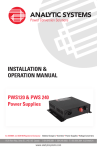
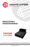
MasterSwitch™
Thank You !
Thank you for selecting the MasterSwitch™ network-manageable power distribution unit
(PDU). The MasterSwitch™ has been designed for many years of reliable, maintenancefree service in combination with your American Power Conversion (APC) Uninterruptible Power Source (UPS). APC is dedicated to the development of high-performance
electrical power conversion and control products and we hope that you will find this
product a valuable, convenient addition to your computing system.
Please read this manual! It provides important safety, installation, and operating
instructions that will help you get the most from your MasterSwitch™.
Save this manual! It includes instructions for obtaining factory service should the
proper operation of the MasterSwitch™ come into question.
Radio Frequency Interference
WARNING: Changes or modifications to this unit not expressly approved by the party
responsible for compliance could void the user’s authority to operate this equipment.
FCC Statement
NOTE: This equipment has been tested and found to comply with the limits for a Class
A digital device pursuant to Part 15 of the FCC Rules. These limits are designed to
provide reasonable protection against harmful interference when the equipment is
operated in a commercial environment. This equipment generates, uses, and can radiate
radio frequency energy and, if not installed and used in accordance with the instruction
manual, may cause harmful interference to radio communications. Operation of this
equipment in a residential area is likely to cause harmful interference in which case the
user will be required to correct the interference at his own expense.
Canadian Department of Communications Statement
This digital apparatus does not exceed the Class A limits for radio noise emissions from
digital apparatus set out in the Radio Interference Regulations of the Canadian Department of Communications.
Le présent appareil numérique n’emet pas de bruits radioélectriques dépassant les limites
applicables aux appareils numériques de la Class A prescrites dans le Règlement sur le
brouillage radioélectrique édicte par le ministère dès Communications du Canada.
Contents
1.
2.
3.
4.
Introduction ................................................... 2
Package Contents ........................................ 3
On-line Documentation ................................ 4
Installation ..................................................... 4
Desktop Installation ................................................... 4
Rack Mount Installation ............................................. 5
5.
6.
7.
8.
9.
10.
Status Indicators ........................................... 6
Initial Setup ................................................... 6
Operation Check .......................................... 7
Troubleshooting ............................................ 7
Service .......................................................... 7
Specifications ............................................... 8
Entire contents copyright © 1997 American Power Conversion.
All rights reserved; reproduction in whole or in part without permission is prohibited.
MasterSwitch, NetShelter and PowerNet are trademarks of APC.
All other trademarks are the property of their respective owners.
1
1. Introduction
The MasterSwitch™ is a network-manageable, intelligent power
distribution unit (PDU) designed to provide control of power for up to
eight 120-VAC electrical devices.
The MasterSwitch™ allows you to:
• Individually control each of eight outlets using a web browser, an SNMP
browser or a terminal program.
• Remotely and individually reboot hung servers.
• Remove power to non-essential loads.
• Sequentially apply power to equipment plugged into the MasterSwitch™.
As shown in Figure 1, the MasterSwitch™:
• Has a 15-foot, attached input-line cord.
• Has eight 120-VAC, 15-Amp power receptacles (4 x NEMA 5-15).
• Has a 15-Amp circuit breaker.
Figure 1: MasterSwitch™ with Rack-Mounting Brackets and Configuration Cable
As shown in Figure 2, the MasterSwitch™ also features:
• A 9-pin configuration port for connecting the MasterSwitch™ to a terminal (or
terminal emulator) during the setup procedures (Section 4). This connection is
made using the 9-pin cable (APC PN 940-0103) that comes with the
MasterSwitch™.
• An 8-pin RJ45 jack for connecting the MasterSwitch™ to a 10Base-T Local
Area Network (LAN).
• Two LEDs (Link and Status) for monitoring the network connection.
• Eight LEDs (one for each receptacle) to report power on (lit) or off (not lit)
conditions of the MasterSwitch™ power outlets.
• A reset button that reinitializes the MasterSwitch™ without affecting its outlet
power (warm reboot).
2
Reset
Button
Figure 2: MasterSwitch™ Front Panel
2.
Package Contents
In addition to this installation guide, the MasterSwitch™ also comes with the following
items:
• Two rack-mounting brackets.
• Four screws for attaching the rack-mounting brackets to the MasterSwitch™ .
• One 9-pin male-to-9-pin female cable (APC PN 940-0103) for connecting a
terminal (or terminal-emulator) to the MasterSwitch™ for configuration.
• One diskette which contains a pdf-formatted copy of the MasterSwitch™ User’s Guide (pduguide.pdf), as well as a copy of the MasterSwitch-management information base (MasterSwitch-MIB) that provides the object identifiers
(OIDs) needed to use an SNMP browser to monitor and control the MasterSwitch™.
• One copy of the warranty card.
Note:
Please fill out and return the warranty card. This card not only
provides us with valuable, welcomed feedback on how we can refine
our products to better serve your needs, but it also enables us to notify
you about important product updates and changes.
Release notes may also be included to advise you of any information that has become
relevant since this installation guide (and the on-line user’s guide included on the
diskette) were last revised.
3
3.
On-line Documentation
The diskette that comes with the MasterSwitch™ includes a copy of
the MasterSwitch™ - User’s Guide in portable data format
(pduguide.pdf). This guide can be read using Acrobat Reader, a free
application available from Adobe (http//:www.adobe.com). If you do
not have web capabilities, a copy of this guide is available from APC’s
FTP site (apccorp.apcc.com).
4. Installation
The MasterSwitch™, which connects to a 10Base-T Local Area
Network (LAN) through the RJ45 jack on the front of the unit, can be
used as a freestanding desktop unit or mounted in a NetShelter™
cabinet (or other 19” NEMA rack).
Desktop Installation
The MasterSwitch™ is equipped with rubber feet for desktop use and
can be located wherever space permits:
1. Place the MasterSwitch™ in its permanent location. Make sure that this location
is within 15 feet (4.6 meters) of a single-phase, 120-VAC, 15-Amp outlet, and
that the back of the unit (receptacle side) will be readily accessible.
2. Plug the male end of your network interface cable (not supplied with the
MasterSwitch™) into the RJ45 jack on the front of the MasterSwitch™.
3. Plug the MasterSwitch™ power cord into the single-phase, 120-VAC, 15-Amp
outlet.
4. Refer to Section 4 for information on setting up the MasterSwitch™.
4
Rack Mount Installation
To mount the MasterSwitch™ in a NetShelter™ (or other 19-inch
NEMA rack):
1. Peel the rubber feet from the bottom of the MasterSwitch™.
2. Refer to Figure 3 and use a #2 Phillips-head screwdriver, and two of the
supplied screws, to attach each mounting bracket to the MasterSwitch™.
NOTE: The mounting brackets can be attached at various positions along the
side of the chassis. Choose a position that will not cause the mounted
MasterSwitch™, or attached cables, to interfere with closing the
cabinet door, or to otherwise protrude from the cabinet. If more than
two mounting holes are aligned, choose the pair that are farthest apart.
Figure 3: Attaching Mounting Brackets
3. Refer to Figure 4 and use 4 cage nuts and machine screws (not supplied with
the MasterSwitch™) to mount the MasterSwitch ™ into the NetShelter™ cabinet.
If the MasterSwitch™ is being installed in a cabinet other than a NetShelter™,
use the hardware that is appropriate for the cabinet.
4. Plug the male end of your network interface cable (not supplied with the
MasterSwitch™) into the RJ45 jack on the front of the MasterSwitch™.
5. Plug the MasterSwitch™ power cord into a single-phase 120-VAC, 15-Amp
outlet.
6. Refer to Section 4 for information on setting up the MasterSwitch™.
Figure 4: Mounting in a NetShelter™ Cabinet
5
5.
Status Indicators
The MasterSwitch™ has eight receptacle status LEDs located on the
front panel. When a status LED is on, it indicates the related receptacle has power; When a status LED is off, its receptacle does not
have power.
The MasterSwitch™ also has two network connection status LEDs,
also located on the front panel, that indicate the following states:
LE D
S t a te
I n d i c a ti o n
L i n k - T X /R X
B lin k in g
G ree n
M a s t e r S w it c h ™
n e tw o r k .
O ff
N e t w o r k o r M a s t e r S w it c h ™
S o lid G r e e n
M a s t e r S w it c h ™
B lin k in g
G ree n
N e t w o r k c o n f ig u r a t io n v a l u e s h a v e n o t b e e n
d e f in e d f o r t h e M a s t e r S w i t c h ™ .
F la s h in g
R e d ( S lo w )
P r o c e s s i n g b o o tp .
S o lid R e d
H a r d w a r e F a i lu r e .
S ta tu s
is c o n n e c t e d t o a w o r k in g
c o n n e c t i o n f a i lu r e .
is o k .
Table 1: Network Connection (10Base-T) Status Indicators
6.
Initial Setup
Before the MasterSwitch™ can operate over the network it needs to
have certain address values defined. These values can be set (configured) by a BOOTP server (the MasterSwitch™ comes with BOOTP
enabled) or by using a terminal (or terminal emulator) connected to
the 9-pin configuration port on the front panel of the MasterSwitch ™.
NOTE: Refer to the MasterSwitch™ - User’s Guide for information on the initial
configuration of the MasterSwitch™. A copy of this guide, in portable data
format is provided on the diskette that came with the MasterSwitch™.
In addition, if you want to use SNMP to configure and control the
MasterSwitch™, you will need to load and compile APC’s MasterSwitch-MIB at any network management station (NMS) you will use
for SNMP control of the MasterSwitch™.
NOTE: The MasterSwitch-MIB is provided on the diskette that came with the
MasterSwitch™. See the documentation for the NMS you want to use this
MIB for instructions on loading and compiling MIBs.
6
7.
Operation Check
After the MasterSwitch ™ is installed and set up:
1. Confirm that the network connection status (Link and Status) LEDs are on (lit).
2. Confirm that all eight of the receptacle status LEDs are on (lit).
8.
Troubleshooting
P r o b le m
P o s s ib le C a u s e
S o lu tio n
N o p o w e r f ro m a n y
B lo w n M a s te rS w it ch ™ c irc u it
b r e a k e r o r n o in p u t p o w e r .
R e s e t c irc u it b r e a ke r, o r
c o r re ct in p u t p o w e r p ro b le m .
C o n n e ct io n to n e tw o rk is
f a u lty .
M a ke su re n e tw o r k c a b le is
s e c u r e ly co n n e c t e d to th e
M a st e rS w itc h ™ a n d n e t w o rk .
A m p s d ra w n b y lo a d
e q u ip m e n t e x ce e d s 1 5 - a m p
m a xim u m .
L im it lo a d e q u ip m e n t t o t h o se
d e v ice s w h ic h t o g e th e r d r a w
le s s th a n 1 5 a m p s.
r e c e p t a c le .
N e t w o rk c o n n e c t io n L E D s
d o n o t c o m e o n.
C ir c u it b r e a k e r
c o n t in u o u s l y o r f r e q u e n t ly
t r ip s .
Table 2: Troubleshooting
9.
Service
If the MasterSwitch™ requires service:
1. Check the MasterSwitch™ using the troubleshooting chart in section 6 before
calling for service.
2. Note the model number of the MasterSwitch™, the serial number, and the date
purchased. See the back cover of this manual for the correct telephone number
and call customer service. A technician will ask you to describe the problem
and help solve it over the phone, if possible, or will give you an RMA#. If
customer service is not available in your area, call the dealer that sold the
MasterSwitch™. If it is under warranty, repairs are free. If not, there will be a
charge for repair.
3. It is important to pack the MasterSwitch™ properly to avoid damage in transit.
If possible, use the original packing materials. Damage sustained in transit is
not covered under warranty.
4. Include a letter with your name, RMA#, address, copy of the sales receipt,
description of the trouble, your daytime phone number, and a check (if
necessary).
5. Mark the RMA# on the outside of the package. The factory cannot accept any
package without this marking.
6. Return the MasterSwitch™ by insured, prepaid carrier to the address given by
the technician.
7
10. Specifications
Electrical
Input:
Nominal input voltage:
Acceptable input voltage:
Nominal input frequency:
Overcurrent protection:
Input connector:
120 VAC
100 - 140 VAC
50/60 Hz
15 A resettable circuit breaker
15 foot (4.5 m) attached NEMA 5-15 line cord
Output:
Output connectors:
8 NEMA 5-15 receptacles
Maximum total current draw:
15 A
Physical
Size (H x W x D):
(without mounting brackets)
(with mounting brackets)
2.125 x 17 x 6.5 inches (5.4 x 43.2 x 16.5cm)
1.875 x 19 x 6.5 inches (4.8 x 48.3 x 16.5cm)
Weight:
6.5 lb. (3.0 kg)
Shipping weight:
10.0 lb. (4.5 kg)
Environmental
Operating elevation (storage):
0 to 3,000 m (0 to 15,000 m)
Operating temperature (storage):
0 to 40 °C (0 to 45 °C)
Approvals
EMC verification:
Electromagnetic immunity:
Table 3: MasterSwitch™ Specifications
8
Limited Warranty
American Power Conversion (APC) warrants its products to be free from defects in
materials and workmanship for a period of two years from the date of purchase. Its
obligation under this warranty is limited to repairing or replacing, at its own sole option,
any such defective products. To obtain service under warranty you must obtain a
Returned Material Authorization (RMA) number from APC or an APC service center.
Products must be returned to APC or an APC service center with transportation charges
prepaid and must be accompanied by a brief description of the problem encountered and
proof of date and place of purchase. This warranty does not apply to equipment which
has been damaged by accident, negligence, or misapplication or has been altered or
modified in any way. This warranty applies only to the original purchaser who must have
properly registered the product within 10 days of purchase.
EXCEPT AS PROVIDED HEREIN, AMERICAN POWER CONVERSION MAKES
NO WARRANTIES, EXPRESS OR IMPLIED, INCLUDING WARRANTIES OF
MERCHANTABILITY AND FITNESS FOR A PARTICULAR PURPOSE. Some
states do not permit limitation or exclusion of implied warranties; therefore, the aforesaid
limitation(s) or exclusion(s) may not apply to the purchaser.
EXCEPT AS PROVIDED ABOVE, IN NO EVENT WILL APC BE LIABLE FOR
DIRECT, INDIRECT, SPECIAL, INCIDENTAL, OR CONSEQUENTIAL DAMAGES ARISING OUT OF THE USE OF THIS PRODUCT, EVEN IF ADVISED OF
THE POSSIBILITY OF SUCH DAMAGE. Specifically, APC is not liable for any costs,
such as lost profits or revenue, loss of equipment, loss of use of equipment, loss of
software, loss of data, costs of substitutes, claims by third parties, or otherwise.
Life Support Policy
As a general policy, American Power Conversion (APC) does not recommend the use of
any of its products in life support applications where failure or malfunction of the APC
product can be reasonably expected to cause failure of the life support device or to
significantly affect its safety or effectiveness. APC does not recommend the use of any
of its products in direct patient care. APC will not knowingly sell its products for use in
such applications unless it receives in writing assurances satisfactory to APC that (a) the
risks of injury or damage have been minimized, (b) the customer assumes all such risks,
and (c) the liability of American Power Conversion is adequately protected under the
circumstances.
Examples of devices considered to be life support devices are neonatal oxygen analyzers,
nerve stimulators (whether used for anesthesia, pain relief, or other purposes),
autotransfusion devices, blood pumps, defibrillators, arrhythmia detectors and alarms,
pacemakers, hemodialysis systems, peritoneal dialysis systems, neonatal ventilator
incubators, ventilators for both adults and infants, anesthesia ventilators, and infusion
pumps as well as any other devices designated as critical by the U.S. FDA.
Hospital grade wiring devices and leakage current may be ordered as options on many
APC UPS systems. APC does not claim that units with this modification are certified or
listed as Hospital Grade by APC or any other organization. Therefore these units do not
meet the requirements for use in direct patient care.
Toll free technical support: Addresses:
United States and Canada:
1-800-800-4272
International:
Austria:
0660 6480
Belgium:
0800 15063
Denmark:
800 18 153
Finland:
9800 13 374
France:
0 800 09 24 07
Germany:
0130 818907
Holland:
0602 24655
Ireland:
1 800 702000
Israel:
177 353 2206
Italy:
1678 74731
Japan:
0120-80-60-90
Norway:
800 11 632
Portugal:
050 553182
Russia:
7095 230 6297
South Africa: 0800 994206
Spain:
900 95 35 33
Sweden:
020 795 419
Switzerland: 1556 177
Turkey:
0800 35390275
UK:
0800 132990
American Power Conversion Corporation
132 Fairgrounds Road
P. O. Box 278
West Kingston, RI 02892
USA
In areas without toll free numbers:
+1 401 789 5735 (USA) or
+353 91 702020 (Ireland)
American Power Conversion Corporation
Omodaka Bldg 5F 1-9-7 Shibaura
Minato-ku
Tokyo, 105
Japan
American Power Conversion Corporation
(A. P. C.) b. v.
Ballybritt Business Park
Galway
Ireland
American Power Conversion Corporation
4 Rue St Claire Deville
Lognes F-77185
France
Serial number:
MAC Address:
Entire contents copyright © 1997 American Power Conversion.
All rights reserved; reproduction in whole or in part without permission is prohibited.
MasterSwitch, NetShelter and PowerNet are trademarks of APC.
All other trademarks are the property of their respective owners.
990-0154
Rev. 1.0
2/97