1
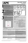
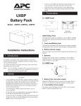
990-0149
4/00
Entire contents copyright © 2000 American Power Conversion. All rights reserved.
Reproduction in whole or in part without permission is prohibited.
APC, Smart-UPS, Matrix UPS, Symmetra, Power Array, and PowerChute are all trademarks or registered
trademarks of APC. All other trademarks, product names, and corporate names are the property of their
respective owners and are used for informational purposes only.
Configuring network settings 6
Configuration options 6
Management Card Wizard 6
Accessing the network interface 7
For more information 8
Setting up network shutdown software 8
Testing your configuration 8
Enabling remote control 9
American Power Conversion Corporation
Ballybritt Business Park
Galway
Ireland
American Power Conversion Corporation
132 Fairgrounds Road
P. O. Box 278
West Kingston, Rhode Island 02892
USA
Configuration 6
Connecting the chassis 4
LED descriptions 5
Addresses:
Connection 4
U.S. & Canada http://www.apcc.com/support
Online Customer Support:
Denmark
France
Germany
Ireland
Italy
Japan
U. K.
800 18 153
0 800 906 483
01300818907
1 800 702000 x 2045
1678 74731
0120-80-60-90
0800 132990
APC Customer Support:
Toll-free
U. S. & Canada
1-877-287-7835
Austria
Belgium
Czech Republic
Finland
Holland
Hungary
Israel
Luxembourg
Norway
Poland
Portugal
South Africa
Spain
Sweden
Switzerland
Turkey
0660 6480
0800 15063
0 800 102063
9800 13 374
0800 0224655
00800 12221
177 353 2206
0800 2091
800 11 632
00800 353 1202
050 553182
0800 994206
900 95 35 33
020 795 419
0800 556177
0800 35390275
Quick Start Guide
Silcon
Management
www.apcc.com
APC Customer Support:
Toll-free
1
3
2
Installation continued
Installation
Introduction
All the information needed to set up the management of your
UPS is contained in this quick start guide. If you need
additional information, please consult the appropriate
document listed below:
• Printed user guide for your Silcon DP300E Series UPS
• Triple Chassis for Silcon DP300E Series UPSs printed
installation manual
• Web/SNMP Management Card Installation and Quick
Start Guide on the CD (PDF)
• Web/SNMP Management Card User Guide on the CD
(PDF)
• Web/SNMP Management Card Release Notes on the CD
(PDF)
For more
information
This document provides quick instructions for setting up the
management of your installed APC Silcon DP300E series UPS.
The setup will involve:
• Mounting the APC Silcon Triple Chassis (AP9604S)
• Connecting the chassis to the UPS and to your network
• Configuring the required settings of your Silcon
management card
• Using your Web browser to connect to the network
interface of your Silcon management card
• Downloading and installing PowerChute network
shutdown software
• Testing your configuration
Overview
Installation options 2
Placing on a desktop 2
Mounting in an enclosure 2
Mounting on a wall 3
Installation 2
Overview 1
For more information 1
Introduction 1
Silcon Customer Support:
Toll-free
Contents
1 Choose a permanent location for the chassis. Make sure that
the rear panel of the chassis is accessible.
Note: We recommend that you not place the chassis on top of
the UPS to ensure proper airflow to the UPS.
2 Continue with “Connecting the chassis” on page 4.
Placing on a
desktop
You can install the Silcon Triple Chassis in one of three ways.
It can be:
• placed on a desktop
• mounted in a NetShelter enclosure or other 19" rack
• mounted on a wall
Installation
options
Mounting in an
enclosure
1 Remove the rubber feet from the bottom of the chassis.
2 Fasten each rack-mount bracket (supplied) to the chassis as
shown, using the two flat head mounting screws (supplied)
and a #2 Phillips screwdriver.
Mounting in an
enclosure,
continued
4 Continue with “Connecting the chassis” on page 4.
Mounting on a
wall
1 Fasten the wall mounting brackets (supplied) to the chassis,
using the flat head screws (supplied) and a #2 Phillips
screwdriver.
2 Attach the assembly to the wall using mounting hardware
(not supplied) that is sturdy enough to support the weight of
the chassis.
Note: The mounting brackets attach at various hole positions
on the side of the chassis. Choose a position that will
prevent connected cables from being pinched by the
door. If more than two mounting holes are aligned, use
the pairs that are the farthest apart.
3 Attach the assembly to the rack using four caged nuts and
mounting screws supplied with your NetShelter enclosure.
(See the figure on the next page.)
Note: Refer to the user documentation supplied with your
enclosure or rack for more detailed mounting
instructions.
Continued on next page
3 Continue with “Connecting the chassis” on page 4.
990-0149
4/00
Entire contents copyright © 2000 American Power Conversion. All rights reserved.
Reproduction in whole or in part without permission is prohibited.
APC, Smart-UPS, Matrix UPS, Symmetra, Power Array, and PowerChute are all trademarks or registered
trademarks of APC. All other trademarks, product names, and corporate names are the property of their
respective owners and are used for informational purposes only.
Configuring network settings 6
Configuration options 6
Management Card Wizard 6
Accessing the network interface 7
For more information 8
Setting up network shutdown software 8
Testing your configuration 8
Enabling remote control 9
American Power Conversion Corporation
Ballybritt Business Park
Galway
Ireland
American Power Conversion Corporation
132 Fairgrounds Road
P. O. Box 278
West Kingston, Rhode Island 02892
USA
Configuration 6
Connecting the chassis 4
LED descriptions 5
Addresses:
Connection 4
U.S. & Canada http://www.apcc.com/support
Online Customer Support:
Denmark
France
Germany
Ireland
Italy
Japan
U. K.
APC Customer Support:
Toll-free
Introduction 1
U. S. & Canada
1-877-287-7835
Silcon Customer Support:
Toll-free
Contents
0660 6480
0800 15063
0 800 102063
9800 13 374
0800 0224655
00800 12221
177 353 2206
0800 2091
800 11 632
00800 353 1202
050 553182
0800 994206
900 95 35 33
020 795 419
0800 556177
0800 35390275
www.apcc.com
APC Customer Support:
Toll-free
For more
information
Overview 1
For more information 1
Austria
Belgium
Czech Republic
Finland
Holland
Hungary
Israel
Luxembourg
Norway
Poland
Portugal
South Africa
Spain
Sweden
Switzerland
Turkey
Overview
Installation 2
800 18 153
0 800 906 483
01300818907
1 800 702000 x 2045
1678 74731
0120-80-60-90
0800 132990
Silcon
Management
Introduction
Installation options 2
Placing on a desktop 2
Mounting in an enclosure 2
Mounting on a wall 3
Quick Start Guide
1
3
2
Installation continued
Installation
This document provides quick instructions for setting up the
management of your installed APC Silcon DP300E series UPS.
The setup will involve:
• Mounting the APC Silcon Triple Chassis (AP9604S)
• Connecting the chassis to the UPS and to your network
• Configuring the required settings of your Silcon
management card
• Using your Web browser to connect to the network
interface of your Silcon management card
• Downloading and installing PowerChute network
shutdown software
• Testing your configuration
Installation
options
You can install the Silcon Triple Chassis in one of three ways.
It can be:
• placed on a desktop
• mounted in a NetShelter enclosure or other 19" rack
• mounted on a wall
Placing on a
desktop
1 Choose a permanent location for the chassis. Make sure that
the rear panel of the chassis is accessible.
Note: We recommend that you not place the chassis on top of
the UPS to ensure proper airflow to the UPS.
2 Continue with “Connecting the chassis” on page 4.
All the information needed to set up the management of your
UPS is contained in this quick start guide. If you need
additional information, please consult the appropriate
document listed below:
• Printed user guide for your Silcon DP300E Series UPS
• Triple Chassis for Silcon DP300E Series UPSs printed
installation manual
• Web/SNMP Management Card Installation and Quick
Start Guide on the CD (PDF)
• Web/SNMP Management Card User Guide on the CD
(PDF)
• Web/SNMP Management Card Release Notes on the CD
(PDF)
Mounting in an
enclosure
1 Remove the rubber feet from the bottom of the chassis.
2 Fasten each rack-mount bracket (supplied) to the chassis as
shown, using the two flat head mounting screws (supplied)
and a #2 Phillips screwdriver.
Mounting in an
enclosure,
continued
4 Continue with “Connecting the chassis” on page 4.
Mounting on a
wall
1 Fasten the wall mounting brackets (supplied) to the chassis,
using the flat head screws (supplied) and a #2 Phillips
screwdriver.
2 Attach the assembly to the wall using mounting hardware
(not supplied) that is sturdy enough to support the weight of
the chassis.
Note: The mounting brackets attach at various hole positions
on the side of the chassis. Choose a position that will
prevent connected cables from being pinched by the
door. If more than two mounting holes are aligned, use
the pairs that are the farthest apart.
3 Attach the assembly to the rack using four caged nuts and
mounting screws supplied with your NetShelter enclosure.
(See the figure on the next page.)
Note: Refer to the user documentation supplied with your
enclosure or rack for more detailed mounting
instructions.
Continued on next page
3 Continue with “Connecting the chassis” on page 4.
5
4
Connection
Connecting the
chassis
1 Locate the UPS cable (APC part number 940-0071). This
cable should be routed from a UPS serial port to a location
outside of the UPS.
If this cable is not routed, contact APC Customer
Support. A certified APC service technician must
route this cable. Do not attempt to route the cable
yourself.
2 Attach the UPS cable to the To UPS port on the front panel of
the chassis.
3 Use the supplied routing clips to secure the cable to the UPS,
if desired.
4 Attach a network cable to the RJ-45 port on the Silcon
management card.
5 Verify that the chassis has power and is operating normally.
See “LED descriptions” on page 5 for a description of the
indications of normal operation.
6
Connection continued
Configuration
LED
descriptions
Configuring
network
settings
The chassis contains a Silcon management card that provides
the network interface. You must configure the network settings
of this management card before it can function on a network.
The required settings are:
• IP address of the Silcon management card
• Subnet Mask
• IP address of the default Gateway
Note: Before you begin configuring network settings, you will
need the MAC address from the Quality Assurance Slip
included with your chassis.
Configuration
options
Choose the configuration method that matches your
environment:
• If you are using Windows™ 95, 98, or NT, see
“Management Card Wizard” on this page.
• If you require direct serial configuration; or if you are a
network administrator and have access to a computer
connected to the local subnet; or if you are using
BOOTP, see the Web/SNMP Management Card
Installation and Quick Start Guide included on the CD.
Management
Card Wizard
The Management Card Wizard provides a quick way to
configure all Silcon management card settings, including the
required network settings described previously. To access the
Management Card Wizard from a Windows™ 95, 98, NT 4.0,
or 2000 workstation, run setup.exe located in the Wizard
subdirectory of the CD-ROM supplied with the a.
If your workstation is configured to run CD-ROMs automatically,
the Wizard installation will begin and you will not need to run the
setup.exe program manually. Follow the on-screen instructions to
install and run the Wizard.
LED
State
Off
The device that connects
the card to the network (a
router, hub, or
concentrator) is off or not
operating correctly.
Flashing
green
The card is receiving data
packets from the network.
Off
The card has no power.
Solid green
The card has valid network
settings.
Flashing
green
The card does not have
valid network settings.
Solid red
The card has detected a
hardware failure.
Blinking red
The card is making BOOTP
requests. The Status LED
must be blinking red for the
Wizard configuration
software to detect that the
card does not have valid
network settings.
Management Card
Link-RX/TX
Management Card
Status
Triple Chassis
Status
Description
Off
The chassis is not receiving
power.
Blinking
quickly
(5 times per
second)
The chassis has not been
configured. See
“Configuring via the
Monitoring Port” on page
10 of the Silcon Triple
Chassis user manual.
Blinking
slowly
(1 time per
second)
The chassis is powered on
but is not communicating
with the UPS.
On
The chassis is operating
normally.
When the Wizard is first run, it will begin searching for
management cards on the network that do not have valid network
settings. If you have properly installed the management card on
the network, the Status LED is blinking red, and the workstation
is on the same subnet as the management card, then the
management card will be detected in about one minute.
Continued on next page
Continued on next page
8
7
Configuration continued
Management
Card Wizard,
continued
Accessing the
network
interface
Configuration continued
If the Wizard has not detected the management card after 2
minutes or your workstation is not connected to the network,
follow these steps:
1 Click Next.
2 Select Express.
3 Click Next.
4 Select Locally (via Serial Port).
5 Click Next.
6 Follow the on-screen instructions to configure your
management card using a serial connection.
If you have configured network settings through the
Management Card Wizard and your card was on the network,
you had the option to launch a Web browser to view the Silcon
management card network interface. If you have used another
method to configure your network settings or did not choose to
launch a Web browser from the Wizard, you can access the
network interface using a Web browser, Telnet, or SNMP. See
the appropriate paragraph below for details.
For more
information
Through Telnet.
1 From your Telnet session, enter the System IP address
of the unit.
2 Log on to the unit. The default User Name and
Password are apc (lowercase).
Through SNMP.
The default read-only community name is public. The
default read/write community name is private.
Note: When the management card reports a non-specific fault,
it is defined on the screen of your Silcon UPS display
unit.
Continued on next page
Configuration continued
After you have configured the settings described in this section, no
further configuration is required. The remaining Silcon
management card properties are pre-configured at the factory.
However, these properties may not be suitable for your
application. See the Web/SNMP Management Card User Guide
included on the CD for more details on how to customize the
management card settings to your system.
Note: Updated management card firmware versions and the
latest user manuals can be found on the Support page on
our Web site: http://www.apc.com/support.
Setting up
network
shutdown
software
PowerChute network shutdown software provides reliable
network-based shutdown of multiple computer systems to
enhance the manageability of APC UPSs.
Note: PowerChute Network Shutdown software is different
from PowerChute plus software.
1 Go to the APC Web site and download the latest version
of PowerChute Network Shutdown software:
www.apc.com/tools/download for your operating
system(s). Be sure to download the installation guide.
2 If you have more than 50 servers connected to your UPS,
download the document called “How to configure greater
than 50 clients”.
3 Follow the instructions in the installation guide.
Testing your
configuration
To test communication between PowerChute Network
Shutdown software and the Silcon management card:
1 View the PowerChute Network Shutdown Event Log:
Launch the Web interface for PowerChute Network
Shutdown software. The Event Log appears on the first
screen.
2 Unplug the network connection from the Silcon
management card.
3 After three minutes, refresh the Event Log. It should
report lost communications.
4 Reconnect the network connection to the Silcon
management card.
5 After one minute, refresh the Event Log. It should report
communication established.
Through a Web browser.
1 From your Web browser, enter the System IP address or
DNS name, if configured, of the unit.
2 Log on to the chassis. The default User Name and
Password are apc (lowercase).
9
Continued on next page
Enabling
remote control
By default, the management card does not allow commands
issued from remote computers. To enable remote control, you
must connect serially to the Silcon management card and
change the default setting.
Connecting Serially through the Control Console.
1 Connect the supplied communication cable (APC part
number 940-0024C) to an available serial port on your
computer and to the Monitoring Port on front panel of
the chassis.
2 Disable PowerChute plus, UNIX Respond, or other
service that may be using the serial port on the
computer.
3 Run a terminal emulator such as Windows™
HyperTerminal.
4 Configure the appropriate serial port with the following
settings: 2400 bps, no parity, 8 data bits, 1 stop bit, and
no flow control.
Note: Some terminal emulators such as HyperTerminal
require that you disconnect and reconnect for the
new serial settings to take effect.
5 From your computer, press ENTER until the user name
prompt appears.
6 Enter the default user name and password: apc, both
lowercase.
7 From the Control Console, preform the following steps
in the order given:
a Choose Device Manager (number 1) from the menu
and press ENTER.
b Choose the appropriate UPS from the menu and press
ENTER.
c Choose Control (number 1) from the menu and press
ENTER.
d Choose Enable Remote Control (number 3) from the
menu, press ENTER, and follow the prompts to enable
remote control.
e Press ESC until the Main menu appears.
f Choose Logout (number 4) from the menu and press
ENTER.
Note: The new settings will not take effect until you log
out.
990-0149
5/00
Entire contents copyright © 2000 American Power Conversion. All rights reserved.
Reproduction in whole or in part without permission is prohibited.
APC, Smart-UPS, Matrix - UPS, Symmetra, Power Array, and PowerChute are all trademarks or registered
trademarks of APC. All other trademarks, product names, and corporate names are the property of their
respective owners and are used for informational purposes only.
Configuring network settings 6
Configuration options 6
Management Card Wizard 6
Accessing the network interface 7
For more information 8
Setting up network shutdown software 8
Testing your configuration 8
Enabling remote control 9
American Power Conversion Corporation
Ballybritt Business Park
Galway
Ireland
American Power Conversion Corporation
132 Fairgrounds Road
P. O. Box 278
West Kingston, Rhode Island 02892
USA
Configuration 6
Connecting the chassis 4
LED descriptions 5
Addresses:
Connection 4
U.S. & Canada http://www.apcc.com/support
Online Customer Support:
Denmark
France
Germany
Ireland
Italy
Japan
U. K.
800 18 153
0 800 906 483
01300818907
1 800 702000 x 2045
1678 74731
0120-80-60-90
0800 132990
APC Customer Support:
Toll-free
U. S. & Canada
1-877-287-7835
Austria
Belgium
Czech Republic
Finland
Holland
Hungary
Israel
Luxembourg
Norway
Poland
Portugal
South Africa
Spain
Sweden
Switzerland
Turkey
0660 6480
0800 15063
0 800 102063
9800 13 374
0800 0224655
00800 12221
177 353 2206
0800 2091
800 11 632
00800 353 1202
050 553182
0800 994206
900 95 35 33
020 795 419
0800 556177
0800 35390275
Quick Start Guide
Silcon
Management
www.apcc.com
APC Customer Support:
Toll-free
1
3
2
Installation continued
Installation
Introduction
All the information needed to set up the management of your
UPS is contained in this quick start guide. If you need
additional information, please consult the appropriate
document listed below:
• Printed user guide for your Silcon DP300E Series UPS
• Triple Chassis for Silcon DP300E Series UPSs printed
installation manual
• Web/SNMP Management Card Installation and Quick
Start Guide on the CD (PDF)
• Web/SNMP Management Card User Guide on the CD
(PDF)
• Web/SNMP Management Card Release Notes on the CD
(PDF)
For more
information
This document provides quick instructions for setting up the
management of your installed APC Silcon DP300E series UPS.
The setup will involve:
• Mounting the APC Silcon Triple Chassis (AP9604S)
• Connecting the chassis to the UPS and to your network
• Configuring the required settings of your Silcon
management card
• Using your Web browser to connect to the network
interface of your Silcon management card
• Downloading and installing PowerChute network
shutdown software
• Testing your configuration
Overview
Installation options 2
Placing on a desktop 2
Mounting in an enclosure 2
Mounting on a wall 3
Installation 2
Overview 1
For more information 1
Introduction 1
Silcon Customer Support:
Toll-free
Contents
1 Choose a permanent location for the chassis. Make sure that
the rear panel of the chassis is accessible.
Note: We recommend that you not place the chassis on top of
the UPS to ensure proper airflow to the UPS.
2 Continue with “Connecting the chassis” on page 4.
Placing on a
desktop
You can install the Silcon Triple Chassis in one of three ways.
It can be:
• placed on a desktop
• mounted in a NetShelter enclosure or other 19" rack
• mounted on a wall
Installation
options
Mounting in an
enclosure
1 Remove the rubber feet from the bottom of the chassis.
2 Fasten each rack-mount bracket (supplied) to the chassis as
shown, using the two flat head mounting screws (supplied)
and a #2 Phillips screwdriver.
Mounting in an
enclosure,
continued
4 Continue with “Connecting the chassis” on page 4.
Mounting on a
wall
1 Fasten the wall mounting brackets (supplied) to the chassis,
using the flat head screws (supplied) and a #2 Phillips
screwdriver.
2 Attach the assembly to the wall using mounting hardware
(not supplied) that is sturdy enough to support the weight of
the chassis.
Note: The mounting brackets attach at various hole positions
on the side of the chassis. Choose a position that will
prevent connected cables from being pinched by the
door. If more than two mounting holes are aligned, use
the pairs that are the farthest apart.
3 Attach the assembly to the rack using four caged nuts and
mounting screws supplied with your NetShelter enclosure.
(See the figure on the next page.)
Note: Refer to the user documentation supplied with your
enclosure or rack for more detailed mounting
instructions.
Continued on next page
3 Continue with “Connecting the chassis” on page 4.