1
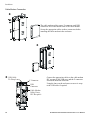
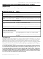
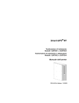
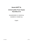
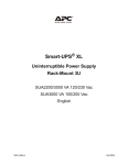
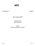
Broadband
Automatic Disconnect Switch
User Manual
Loca
l Pow
er
Re mo
te Pw
er
Rese
t/Test
Loca
l 63V
Fault
Prima
ry/
Seco
nda ry
Se lec
t
Prim
ary
Se con
dary
220V
No rm
al
990-1929
09/2004
Introduction
Introduction
About this unit
Redundant power and output voltage monitoring for Broadband cable systems is provided with the use of two
APC Automatic Disconnect Switches and two Ferroresonant Power Supplies (FRP).
Safety
Electrical Warnings
Do not work alone under hazardous conditions.
High current through conductive materials could cause severe burns.
Do not work alone under hazardous conditions.
High current through conductive materials could cause severe burns.
Do not handle any metallic connector before the power hs been disconnected.
When grounding cannot be verified disconnect the equipment from the utility
power outlet before installing or connecting to other equipment. Reconnect the
power cord only after all connections are made.
Check that the power cord(s), plug(s), and socket(s) are in good condition.
Replacement of fuses or other parts must be with identical types and ratings.
Substitution of nonidentical parts may cause safety and fire hazards.
In order to maintain compliance with the EMC directive for products sold in
Europe, output cords attached to the UPS should not exceed 10 meters in length.
Specifications
Environmental Specifications
Temperature
Operating: 32° to 122°F (0° to 50°C)
Storage: 5° to 122°F (-15° to 50°C)
Humidity
0 to 95%
Elevation
0 to 10,000 feet (0 to 3,000 meters)
Broadband Automatic Disconnect Switch User Manual
3
Installation
Electrical Specifications
Utility Power
Cable
Input
Connection
Three Position
Terminal Block
Cable Adapter (5/8-24)
Terminal Block to Coax Center Conductor
Nominal Voltage
220 V
63 V
Allowable Input range
165-270 V
40-75 V
Maximum Current
15 A
18 A
Input Current Limiting
10 A
N/A
Three Position
Terminal Block
Cable Adapter (5/8-24)
Terminal Block to Coax Center Conductor I
Output
Connection
Allowable Output range
40-75 V
Initial Connection Delay
Primary - None
Secondary - 5.5 seconds
Time to connect attached FRP
to cable system after output
failure
N/A
350 mS maximum
Physical Specifications
Characteristic
Specification
Height/Width/Depth
15” x 7” x 8” (38.1 x 17.8 x 20.3 cm)
Weight
14 lbs (6.4 kg)
Installation
Unpack
Read the Safety Guide before installing this unit. The User Manual and Safety Guide are accessible on the
APC Web site, www.apc.com.
Inspect the unit upon receipt. Notify the carrier and dealer if there is damage.
The packaging is recyclable; save it for reuse or dispose of it properly.
Check the package contents:
4
Broadband Automatic Disconnect Switch User Manual
Installation
•
•
•
•
Automatic Disconnect Switch enclosure
Two mounting brackets
Four screws
One F Connector nut
•
UPS literature kit containing:
– product documentation
– safety information warranty information
Schematic Overview of the Automatic Disconnect Switch System
The user must designate the primary and secondary power supply. Refer to Reset/Test in the Operation section
of this manual for details.
Primary Power Supply
Primary FRP supplying power
to two buildings
220 VAC
FRP1
Secondary Power
220 VAC
FRP2
CS
CS
63 VAC
Power
Power
Broadband Automatic Disconnect Switch User Manual
Bulding 2 cable
63 VAC
blocking
element
Bulding 1 cable
cable
63 VAC
63 VAC
blocking
element
cable
5
Installation
Mount the Automatic Disconnect Switch on the Wall
Do not operate the UPS where there is excessive dust or the temperature or humidity are outside the specified
limits.
The Automatic Disconnect Switch enclosure has side vents. To ensure adequate air flow in and around the unit
there must be 1” (2.5 cm) of space on the right and left sides of the enclosure.
Mount the Automatic Disconnect Switch enclosure on the wall using screws appropriate for the weight of the
unit and the mounting surface material.
Install the Mounting Brackets on the Automatic Disconnect Switch Enclosure
When securing the mounting brackets to the enclosure
two screws must be used in each bracket.
Utility Power Connections
Installation must be performed by a qualified electrician.
Adhere to all local, state, federal, and/or National Electric
Code (NEC) regulations regarding location, permits and
electrical wiring.
Install an approved 20 A high magnetic circuit breaker on the
input side of the Automatic Disconnect Switch.
6
Utility wiring panel
with holes
for wires
Output Hardwire
Input
Hardwire
Broadband Automatic Disconnect Switch User Manual
Installation
Hardwire the Automatic Disconnect Switch
Step •
•
Remove the utility wiring panel located on top of unit.
When required apply a strain relief grommet to the utility wiring panel
holes.
Step •
Route the building wiring through the holes in the
utility wiring panel.
• Connect the 220 V building wiring to the Input
Hardwire terminal block.
Step •
•
Route the input wiring for the FRP/FLM through the
hole in the utility wiring panel.
Connect the FRP/FLM input wiring to the Output
Hardwire terminal block.
Step Reinstall the utility wiring
panel. Secure the panel with
the screw removed in Step .
Broadband Automatic Disconnect Switch User Manual
7
Installation
Cable System Connections
USB Cable
Tie Wrap Lance
F Connector
USB
Connector
Cable Modem
Utility Power
IEC Recepticle
Coax Output
Coax Input
F-Connector Installation
8
Broadband Automatic Disconnect Switch User Manual
Installation
Coax Connection
Coax InputConnects to
FRP Output
Coax OutputConnects to
Cable System
Broadband Automatic Disconnect Switch User Manual
9
Installation
Cable Modem Connection
The cable modem utility power, F-connector, and USB
connectors are located on the back of the cable modem.
Secure the appropriate cables to these connectors before
installing the cable modem in the enclosure.
USB Cable
Tie Wrap Lance
Lo cal P o w er
Rem ot e P o wer
10
F Connector
Connect the appropriate cables to the cable modem
IEC receptacle, the USB port, and the F-connector
located on inside the enclosure.
USB
Connector
Using the lance on the enclosure secure a tie wrap
to the USB cable if required.
Cable Modem
Utility Power
IEC Recepticle
Broadband Automatic Disconnect Switch User Manual
Operation
Start Up
Primary/Secondary Access Panel
To remove the access panel covering the Primary/Secondary Select button
remove the screw that secures the panel to the enclosure. Slide the access
panel slightly to the right and then pull the access panel toward you.
Operation
Indicators and Controls
Circuit Breaker
Local Power
Remote Power
Local Power
Remote Power
Reset/Test
Local 63V Fault
Reset/Test
Local 63V Fault
Primary/
Secondary
Select
Primary/
Secondary
Select
Primary
Secondary
220V Normal
Primary
Secondary
220V Normal
Circuit Breaker: The circuit breaker protects the 220 V input from overload conditions.
Local Power: Green LED indicates that the Automatic Disconnect Switch is providing power to the cable
system.
Remote Power: Green LED indicates the cable system is receiving power from a source other than the
Automatic Disconnect Switch.
Broadband Automatic Disconnect Switch User Manual
11
Operation
Reset/Test: Functionality of this control is dependant upon Automatic Disconnect Switch status.
Primary Status
• The primary Automatic Disconnect Switch is supplying power to the cable system. The Local Power LED
will be illuminated. The Reset/Test button will do nothing.
• When the primary Automatic Disconnect Switch is not supplying power to the cable system the Remote
Power LED will be illuminated. The Automatic Disconnect Switch will perform a test to measure the
output voltage from the local FRP.
Secondary Status
• The secondary Automatic Disconnect Switch is supplying power to the cable system. The Local Power
LED will be illuminated. The secondary Automatic Disconnect Switch will momentarily disconnect the
local power from the cable system allowing the primary system to supply power. If the primary system
begins to supply power, the secondary system will remain disconnected. If the primary system fails to
supply power, the secondary system will immediately begin supplying power to the cable system.
• When the secondary Automatic Disconnect Switch is not supplying power to the cable system the Remote
Power LED will be illuminated. The Automatic Disconnect Switch will perform a test to measure the
output voltage from the local FRP.
Local 63 V Fault: Green LED indicates:
• The FRP/FLM output is outside the specified range during a test.
• The output failed while the Automatic Disconnect Switch was supplying power.
Primary/Secondary Select: This control is used to establish the Automatic Disconnect Switch as the primary
or secondary power source for the cable system.
Primary: Green LED indicates that the Automatic Disconnect Switch is the primary power source.
Secondary: Green LED indicates that the Automatic Disconnect Switch is the secondary power source.
220 V Normal: Green LED indicates that 220 V input is present and within specified limits.
Cable Modem
The cable modem functions only when power is supplied by the Automatic Disconnect Switch to an FRP. If the
FRP fails the cable modem will continue to function.
12
Broadband Automatic Disconnect Switch User Manual
Troubleshooting, Service, Contact, Warranty and Regulatory Information
Troubleshooting, Service, Contact, Warranty and Regulatory Information
Troubleshooting
Use this chart to solve minor installation and operation problems. Refer to the APC Web, site www.apc.com
with complex problems.
Problem and/or Possible Cause
Solution
Unit is on and the 220 V Normal LED is not illuminated
The unit is not wired properly.
Check that the input and output wiring are not reversed.
The circuit breaker is tripped.
Reset the circuit breaker.
The 220 V power is outside the specified
limits.
Check that the 220 V power is within specified limits. Refer to Specifications in this
manual.
Unit is on and the Local 63 V Fault LED is illuminated
The unit is not connecting power to the cable
system.
Check that the coax connections are not reversed.
Check that the FRP/FLM output is within specified limits. Refer to Specifications in
this manual.
Secondary unit will not switch to Remote power when the Test button is pressed
Remote power system is not functioning.
This is normal operation. Verify that the Remote power system is working.
Primary unit is indicating Remote power
Primary unit was powered up after the
secondary unit.
This is normal operation. Press the Reset button on the secondary unit to transfer
power to the primary unit.
The primary FRP/FLM output is not within specified limits. Refer to Specifications in
this manual.
Limited Warranty
American Power Conversion (APC) warrants its products to be free from defects in materials and workmanship for a period of two years
from the date of purchase. Its obligation under this warranty is limited to repairing or replacing, at its own sole option, any such defective
products. To obtain service under warranty you must obtain a Returned Material Authorization (RMA) number from customer support.
Products must be returned with transportation charges prepaid and must be accompanied by a brief description of the problem encountered
and proof of date and place of purchase. This warranty does not apply to equipment that has been damaged by accident, negligence, or
misapplication or has been altered or modified in any way. This warranty applies only to the original purchaser who must have properly
registered the product within 10 days of purchase.
EXCEPT AS PROVIDED HEREIN, AMERICAN POWER CONVERSION MAKES NO WARRANTIES, EXPRESSED OR IMPLIED,
INCLUDING WARRANTIES OF MERCHANTABILITY AND FITNESS FOR A PARTICULAR PURPOSE. Some states do not permit
limitation or exclusion of implied warranties; therefore, the aforesaid limitation(s) or exclusion(s) may not apply to the purchaser.
EXCEPT AS PROVIDED ABOVE, IN NO EVENT WILL APC BE LIABLE FOR DIRECT, INDIRECT, SPECIAL, INCIDENTAL, OR
CONSEQUENTIAL DAMAGES ARISING OUT OF THE USE OF THIS PRODUCT, EVEN IF ADVISED OF THE POSSIBILITY OF
SUCH DAMAGE. Specifically, APC is not liable for any costs, such as lost profits or revenue, loss of equipment, loss of use of equipment,
loss of software, loss of data, costs of substitutes, claims by third parties, or otherwise.
Broadband Automatic Disconnect Switch User Manual
13
Troubleshooting, Service, Contact, Warranty and Regulatory Information
Service
If the unit requires service do not return it to the dealer. Follow these steps:
1. Review the problems discussed in Troubleshooting to eliminate common problems.
2. If the problem persists, contact APC Customer Support through the APC Web site, www.apc.com.
– Note the model number of the unit, the serial number, and the date purchased. If you call APC
Customer Support, a technician will ask you to describe the problem and attempt to solve it over
the phone. If this is not possible, the technician will issue a Returned Material Authorization
Number (RMA#).
– If the unit is under warranty, repairs are free.
– Procedures for servicing or returning products may vary internationally. Refer to the APC Web
site for country specific instructions.
3. Pack the unit in its original packaging. If this is not available, refer to the APC Web site for information
about obtaining a new set.
– Pack the UPS properly to avoid damage in transit. Never use Styrofoam beads for packaging.
Damage sustained in transit is not covered under warranty.
4. Mark the RMA# on the outside of the package.
Return the unit by insured, prepaid carrier to the address given to you by Customer Support.
Contact APC
Refer to the APC Web site, www.apc.com. Select the appropriate country from the country selection field, and
select the Support tab at the top of the web page.
Regulatory Agency Approvals and Radio Frequency Warnings
FCC Compliance Notice
This equipment has been tested and found to comply with the limits for a Class A digital device, pursuant to part 15 of the FCC Rules.
These limits are designed to provide reasonable protection against harmful interference when the equipment is operated in a commercial
environment. This equipment generates, uses, and can radiate radio frequency energy. If it is not installed and used in accordance with
the instruction manual, it may cause harmful interference to radio communications. Operation of this equipment in a residential area is
likely to cause harmful interference in which case users will be required to take whatever measures may be necessary to correct the
interference at their own expense.
®
LISTED 42C2
E95463
Entire contents copyright © 2004 by American Power Conversion Corporation. All rights reserved. Reproduction in whole or in part
without permission is prohibited.
APC, Smart-UPS, and PowerChute are registered trademarks of American Power Conversion Corporation. All other trademarks are the
property of their respective owners.
14
Broadband Automatic Disconnect Switch User Manual