1
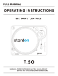
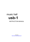
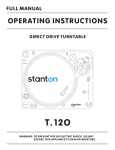
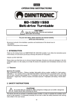
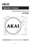
USER INSTRUCTIONS
professional products designed for the working dj.™
User Instructions
Thank you for purchasing this American DJ® product. The TTB-2500 requires
some assembly. Please read the following instructions before installing or
using your new unit. The TTD-2500 has a 2 year limited warranty!
CAUTION! - Keep this device away from rain and moisture!
Name of Parts
1.
2.
3.
4.
5.
6.
7.
8.
9.
10.
11.
12.
13.
14.
15.
16.
17.
18.
19.
20.
21.
22.
23.
45-rpm Adapter
Turntable Platter
Center Spindle
Power Switch
Start/Stop Button
Strobe Dots
Target Light
LED display for speed indication
Green LED: pitch control (11)
is in center click position and the
speed is quartz-controlled.
Red LED: pitch control (11) is not in
center position.
Headshell
Speed Select Buttons
Pitch Adjustment (+/-10%)
Pitch Control Slider
Tonearm
Anti-skate Knob
Counterweight
Spare phono cartridge slot
Hinge for dust cover
Trim control for changing the
range of the pitch adjustment (11, 12).
Right RCA output jack (red)
Left RCA output jack (white)
Ground (GND)
Remote Start/Stop 1/4” output
jack
Beat output for Beat Analyser
19 20
21
23
Before Use
Check for the following parts included
in the package with the main unit.
• Turntable Platter • Slip mat
• Dust Cover • 45-rpm adapter
• Counterweight • Headshell
• User instructions
NOTES:
• Do not connect the AC power plug before assembly has
been completed.
• Before turning the power on, make sure once again all the
connections and power voltage settings are correct.
Always turn off the power when connecting or disconnecting.
• Read this manual carefully before using the unit. Be sure to
store the manual in a safe place for future reference.
22
Warranty & Service
The TTB-2500 has a 2 year limited
warranty. Mail in warranty card as
soon as possible.
R
L GND
BEAT REMOTE
BACK PANEL
TTB-2500 User Instructions page 2
For service, contact your local
American DJ® Dealer.
User Instructions
Assembly
1.
2.
3.
4.
5.
Remove the main unit with the packing from the box and take off the packing.
Set the 45-rpm adapter on the main unit.
Inset the turntable platter onto the center spindle.
Set the slip mat on the platter.
Installation of cartridge: When installing a cartridge, refer to the operating instructions of that cartridge.
During installation, attach the stylus protector to guard the stylus tip from damage.
(a) Connect the lead wires to the cartridge terminals. The terminals of most cartridges are color coded. Connect
each lead wire to the terminal of the same color.
WHITE (L+)..............Left channel+ BLUE (L-)..............Left channelRED (R+)..............Right channel+ Green (R-)..............Right channel(b) Install the cartridge to the headshell and tighten it with screws provided with the cartridge.
6. Inset the headshell into the front end of the tonearm, then turn the lock nut counterclockwise with the headshell
firmly held horizontally.
7. Slide counterweight onto tonearm. Twist it lightly and it will screw onto the rear shaft of the tonearm.
8. Adjustment of horizontal zero (0) balance and stylus pressure:
(a) Remove the stylus protector, do not touch the stylus tip during the adjustment.
(b) Set the cueing lever to the lower position.
(c) Release the arm clamp and lift the tonearm from the arm rest to free it.
(d) Rotate the counterweight until the tonearm is approximately balanced horizontally (floats freely).
(e) Refasten the tonearm with the arm clamp.
(f) Hold the counterweight stationary with one hand and rotate only the stylus-pressure ring to bring the number
“o” of the ring into alignment with he center line on the tonearm rear shaft.
(g) Rotate the counterweight counterclockwise until the scale shows the value corresponding to the pressure of the
used stylus. The stylus pressure of the installed pick-up system is 2g. Should you use a separate pick-up
system, please follow the manufacturer’s instruments.
9. Set the anti-skating control knob to the same value as the stylus pressure.
10. Install the dust cover to the main unit.
Placement
•
•
•
Do not place the unit in a location where it will be exposed to direct sunlight or near a heating appliance.
Do not place the unit in a location where there is high humidity or a lot of dust.
Cartridge may pick up slight sound pressure or vibrations of the speakers coming along the floor or though the air
resulting in howling. Find a location which is very stable and vibration free.
• The legs have functions for adjusting the height of the unit itself. Adjust the legs to stabilize the main body
horizontally.
Connections
1. Connect the power cord to the auxiliary power outlet on the rear panel of your amplifier or receiver or to a household
AC outlet.
2. Connect the unit output terminals to the the PHONO jack of your American DJ Mixer or receiver.
Output terminals
Mixer (Receiver)
L (White) (18) ----------------------------> L Channel
R (Red) (19) -----------------------------> R Channel
GND (Spade) (21) ---------------------> Ground
NOTE: Be sure to connect the ground terminals firmly to the Mixer or receiver. If this connection is not made or is
loose, a power source “HUM” will result.
TTB-2500 User Instructions page 3
User Instructions
Operation
1. Push the power button (4) to turn on the power, the speed indicator (8) and the strobe-illuminator will light up.
2. Place a record on the slipmat. When playing a 45-rpm record with a large center hole, place the 45-rpm adapter (1)
on the center spindle.
3. Set the speed (10) to match the record.
4. Remove the stylus protector, release the arm clamp.
5. Set the cueing lever to the up position.
6. Press the Start/Stop button (5), the turntable platter will start to rotate.
7. Move the tonearm (13) over the desired groove.
8. Set the cueing lever to the down position, the tonearm will descend slowly onto the record and begin playing.
9. When play is finished, raise the cueing lever, move the tonearm with arm clasp.
10. Press the Start/Stop Button (5) to stop the platter from rotating. Push the Power Button (4) to turn off the power.
• SUSPEND PLAY - Set the cueing lever to “UP” position during play, the stylus tip of the cartridge will be lifted
from the record.
• TARGET LIGHT - This unit provides a target light (7) for illuminating the stylus tip during play. After pushing the
target light button, the target light will be raised into position for illuminating the stylus tip. When not in use, keep
the target light lowered.
Changing the Speed
•
•
As long as the pitch control (12) is in center click position, the turntable is operated at quartz controlled rated speed.
The LED display (8) to the left of the Pitch Control Slider (12) will be lit up green.
The speed can be increased or decreased by 10% by the Pitch Control Slider (12). When the slider is moved the LED
(8) will then turn red. If the change of speed does not correspond to the pitch control change, it is possible to correct
with the Trim Control (18). Place a screw driver in the hole where the Trim Control (18) is located. Move the screw
driver left for slower and right for faster (approx. +/-2%).
An incorrect adjustment done on purpose can also be used to have the turntable rotate extremely slow or fast.
The strobe dots (5) at the edge of the turntable are used for speed monitoring.
Remote Control Start/Stop (21)
•
The Start/Stop function can remotely be controlled by a separate switch via a mixing console with a “Fader Start”
function. Activated the “Fader Start” on the mixing console and the turntable automatically begins Start/Stop.
Future American DJ mixers will be equipped with the “Fader Start” function. (1/4” connection)
Beat Indicator (22)
•
The Beat output sends a mono pulse signal and may be used with a separate beat analyzer. (RCA connection)
Maintenance
•
•
•
•
Clean the stylus periodically with a soft brush to prevent the accumulation of dust.
When sound becomes distorted or noisy, check the stylus. If the stylus is worn out, replace it with a new one.
From time to time, the dust cover and turntable cabinet should be wiped down with a soft, dry cloth.
Volatile materials should not be used, such as: alcohol, thinner, benzine etc. They may remove the paint or
damage the luster.
Specifications
•
•
•
•
Power Supply: AC 115V/60Hz, or 230V/50Hz
Power Consumption: 20W
Dimensions (WxDxH): 17.5” x 13 5/8” x 3.5 (6” high with dust cover) /
450mm x 350mm x 148mm
™
Weight: 18 lbs./8kg.
© American DJ® AUDIO
4295 Charter Street
Los Angeles, CA 90058 USA
www.americandj.com
djs wanted.
Specifications subject to change without notice. TTB-2500 User Instructions page 4