1
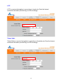
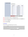
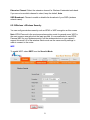
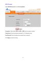
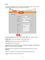
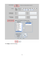
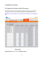
Dual Band Wireless N Router
Model # AR725W
User’s Manual
Rev. 1.0
Table of Contents
1. Introduction................................................................................................................................. 3
1.1 Package Contents .................................................................................................................. 3
1.2 Features ................................................................................................................................. 3
2. Connecting the Router ................................................................................................................ 4
3. Configuring the Router ............................................................................................................... 5
Cable Modem.............................................................................................................................. 5
DSL ............................................................................................................................................. 6
4. Verifying Connection.................................................................................................................. 8
5. Connecting to the Router Wirelessly .......................................................................................... 9
6. Web Configuration Utility ........................................................................................................ 10
6.1 Setup ................................................................................................................................... 10
6.1.1 Setup > Basic Setup ..................................................................................................... 10
6.1.2 Setup > DDNS ............................................................................................................. 16
6.1.3 Setup > MAC Address Clone ...................................................................................... 17
6.1.4 Setup > Advanced Routing .......................................................................................... 18
6.2. Wireless.............................................................................................................................. 19
6.2.1 Wireless > Basic Wireless Settings ............................................................................. 19
6.2.2 Wireless > Wireless Security ....................................................................................... 21
6.2.3 Wireless > Wireless MAC Filter ................................................................................. 30
6.2.4 Wireless > Advanced Wireless Settings ...................................................................... 31
6.3 Security ............................................................................................................................... 33
6.3.1 Security > Firewall....................................................................................................... 33
6.3.2 Security > VPN Passthrough ....................................................................................... 34
6.4 Access Restrictions ............................................................................................................. 35
6.4.1 Access Restrictions > Internet Access Policy.............................................................. 35
6.5 Applications & Gaming ...................................................................................................... 39
6.5.1 Applications & Gaming > Single Port Forwarding ..................................................... 39
6.5.2 Applications & Gaming > Port Range Forwarding ..................................................... 40
6.5.3 Applications & Gaming > Port Range Triggering....................................................... 41
6.5.4 Applications & Gaming > DMZ .................................................................................. 42
6.5.5 Applications & Gaming > QoS.................................................................................... 43
6.6 Administration .................................................................................................................... 51
6.6.1 Administration > Management .................................................................................... 51
6.6.2 Administration > Log................................................................................................... 52
6.6.3 Administration > Diagnostics ...................................................................................... 53
6.6.4 Administration > Factory Defaults .............................................................................. 54
6.6.5 Administration > Firmware Upgrade........................................................................... 55
6.7 Status................................................................................................................................... 56
6.7.1 Status > Router............................................................................................................. 56
6.7.2 Status > Local Network ............................................................................................... 57
6.7.3 Status > Wireless Network .......................................................................................... 58
7. Specifications............................................................................................................................ 59
Appendix – Information................................................................................................................ 60
Technical Support ......................................................................................................................... 60
2
1. Introduction
Thank you for purchasing Airlink101 Dual Band Wireless N Router. The AR725W Dual
Band Wireless N Router provides switchable 2.4 and 5 GHz wireless frequency which
allows more clean channels and less interference for your wireless network. A full range
of security features such as WPA2-PSK, WPA-PSK, and WEP provide the highest level
of wireless network security. The built-in Web Configuration Utility allows you to set up
the router with an easy-to-use user interface.
You will be able to enjoy home entertainment with HD video streaming, VoIP and online
gaming with the high wireless data rate of up to 300Mbps* when used with Airlink101®
Dual Band Wireless N Adapter.
1.1 Package Contents
Before you begin the installation, please check the items of your package:
•
•
•
•
•
Dual Band Wireless N Router
Power Adapter
Ethernet Cable (Cat.5)
Manual CD
Quick Installation Guide
If any item contained is damaged or missing, please contact your local dealer
immediately. Also, keep the box and packaging materials in case you need to ship the
unit in the future.
1.2 Features
•
•
•
•
•
•
•
•
•
•
Built-in dual band (5 / 2.4GHz switchable) AP
More channels, less interference — ideal for wireless congested area
Highest wireless data rate of up to 300Mbps* with 802.11n draft 2.0
WPS button for easy connection with your WPS support wireless adapters
Enjoy HD video streaming, gaming and VoIP with more powerful Dual Band
Wireless N
Advanced NAT+SPI firewall provides fully protection for your wireless connection
QoS (Quality of Service) designed for prioritizing various data traffic to allow
downloading files and playing movies, music, or online gaming at the same time
with uninterrupted data streaming
Supports Universal Plug and Play
Fully backward compatible with 802.11a/b/g
Works best with Airlink101® Dual Band Wireless N USB Adapter
3
2. Connecting the Router
Note: Prior to connecting the router, be sure to power off your computer, DSL/Cable
modem, and the router.
Step 1 Connect one end of a network cable to the INTERNET port of the router and
connect the other end of the cable to the DSL/Cable modem.
Step 2 With another network cable, connect one end of the cable to your computer’s
Ethernet port and connect the other end to one of the LAN ports of the router.
Step 3 Power on the DSL/Cable modem and wait for the lights on the modem to settle
down.
Step 4 Plug the power adapter to the router and connect to an outlet or power strip.
Step 5 Power on your computer.
Step 6 Make sure the INTERNET, WIRELESS, and the LAN port that the computer is
connected to are lit. If not, try the above steps again.
LED Indicators:
How the router connects:
4
3. Configuring the Router
Step 1 Open the web browser (Internet Explorer or Mozilla Firefox), type 192.168.1.1 in
the Address bar and press Enter.
Step 2 Enter admin for both the username and password fields and click OK.
Cable Modem
For most cable modem users, you should be able to connect to the Internet without any
configuration. If your ISP has provided you with a host name, enter it in the optional
Host Name field. Click Apply to save the setting.
5
If your ISP requires a registered MAC Address, click on the MAC Address Clone tab,
select Enabled, and click on the Clone My PC’s MAC button. Click Apply to save the
setting.
If you have trouble connecting to the Internet, please refer to Section 4, Verifying
Connection.
DSL
For DSL users, follow the steps below to configure the router.
Step 1 Select PPPoE from the drop-down menu.
6
Step 2 Enter your username and password provided by your ISP.
Note: Depending on the ISP, you may need to include the domain name with your
username.
Example:
[email protected]
Step 3 Click Apply to save the setting.
You should be able to connect to the Internet now with the wired computer.
If you have trouble connecting to the Internet, please refer to Section 4, Verifying
Connection.
Connect each of your wired computers to an available LAN port on the Router with an
Ethernet cable, and then restart the computer. These computers should be able to
connect to the Internet immediately.
7
4. Verifying Connection
If you have trouble connecting to the Internet, try the following steps.
Step 1 Power off the Cable/DSL modem, router, and computer and wait for 5 minutes.
Step 2 Turn on the Cable/DSL modem and wait for the lights on the modem to settle
down.
Step 3 Turn on the router and wait for the lights on the router to settle down.
Step 4 Turn on the computer.
Step 5 Log in to the router and select the Status tab.
Step 6 Verify that the Internet IP Address, Default Gateway, and at least one of the
DNS fields have valid numbers assigned to them (instead of all 0’s).
If you see all 0’s, click on the IP Address Renew button (for Cable Modem users) or the
Connect button (for DSL users).
If each field has a valid number assigned, the router is connected to the Internet.
8
5. Connecting to the Router Wirelessly
Below are the default wireless settings of the router. You must configure your wireless
network card to the same settings in order to establish a wireless connection to the
router. Please refer to your wireless network card’s manual on how to configure these
settings.
SSID: default
Network Mode: BGN-Mixed
Authentication: Open System
Channel #: 6
WEP: disabled
If you want to change the router’s wireless and security settings, log in to the router and
select the Wireless tab. Click Apply to save the settings after you make changes.
9
6. Web Configuration Utility
This router has a built-in web configuration utility that you can use to configure the
router’s settings. Simply log in to the router using your computer’s web browser.
6.1 Setup
6.1.1 Setup > Basic Setup
This is the default screen when you log in to the router’s web configuration utility. You
can setup your Internet connection here as well as configuring the Network and DHCP
settings and selecting your Time Zone.
10
Internet Setup
There are five Internet Connection Types: DHCP, PPPoE, Static IP, PPTP, L2TP, and
Telstra Cable.
Automatic Configuration - DHCP
When your ISP provides dynamic IP, you can keep this default setting (This is for most
cable modem users). Usually you should be able to connect to the Internet without
changing any configuration. If your ISP has provided you with a host name, enter it in
the optional Host Name field. Click Apply to save the setting.
PPPoE
Usually DSL service provider uses PPPoE for Internet connection. You will need to
provide username and password given by your ISP to connect to the Internet.
11
Static IP
Select Static IP if your ISP provided you the static IP address, Subnet Mask, Default
Gateway and DNS server addresses for Internet connection.
PPTP
Point-to-Point Tunneling Protocol (PPTP) is a service that applies to connections in
Europe only. Enter the Internet connection information provided by your ISP accordingly.
12
L2TP
L2TP is a service that applies to connections in Israel only. Enter the Internet
connection information provided by your ISP accordingly.
Telstra Cable
Telstra Cable is a service that applies to connections in Australia only. Enter the Internet
connection information provided by your ISP accordingly.
13
Network Setup
Router IP
You can change the Router’s IP Address and its Subnet Mask.
DHCP Server Setting
The Router has a built-in DHCP server which can dynamically assign IP address to
each device on your network. The DHCP Server is Enabled by default, if you already
have a DHCP server on the network, you need to select Disabled.
Start IP Address: Give a value for the dynamically assigning IP address to start with.
Because the Router’s default IP address is 192.168.1.1, the Starting IP Address must
be 192.168.1.2 or greater, but smaller than 192.168.1.253. The default Starting IP
Address is 192.168.1.100.
Maximum Number of Users: Enter the maximum number of PCs that you want the
DHCP server to assign IP addresses to. This number cannot be greater than 253. The
default is 50.
Client Lease Time: The Client Lease Time is the amount of time a network user will be
allowed connection to the Router with their current dynamic IP address.
Static DNS 1~3: Enter up to 3 DNS addresses for your network.
DHCP Reservation: If you want to assign a static IP Address to one of the computers
in your network, click on the DHCP Reservation button.
14
Step 1 Enter the Static IP Address in the Assign this IP field.
Step 2 Enter the MAC address of the corresponding computer in the To this MAC field.
Step 3 Check the Enabled box.
Step 4 Click Save Settings.
Time Settings
Set up the time zone and daylight saving for the Router.
15
6.1.2 Setup > DDNS
Dynamic DNS (DDNS) allows any user who wishes to access your server to reach it by
a registered DNS name instead of an IP address. Before you enable DDNS, you need
to register an account with one of the DDNS providers listed in the drop-down menu.
To Enable DDNS, select the DDNS provider you have registered with and enter the
required fields. Click Apply to save the setting.
16
6.1.3 Setup > MAC Address Clone
Some ISPs require a registered MAC address to access the Internet. You can use the
following steps to clone your PC’s registered MAC address to access the Internet.
Step 1 Select Enabled from the drop-down menu.
Step 2 Click the Clone My PC’s MAC button.
Step 3 Click Apply to save the setting.
17
6.1.4 Setup > Advanced Routing
You can configure your own static routing table using the Advanced Routing function.
To see the current routing table, click on Show Routing Table button.
Be sure to click Apply to save each entry.
18
6.2. Wireless
6.2.1 Wireless > Basic Wireless Settings
Wireless Configuration - Manual
To configure the Wireless settings, click on Manual.
19
You can configure the router’s basic wireless settings on this screen.
Network Mode: If you have 802.11b/g/n 2.4GHz devices on the wireless network,
select BGN-Mixed. If you have 802.11a/n 5GHz devices on the wireless network, select
AN-Mixed.
Note: If your wireless computer cannot detect the router after you selected AN-Mixed,
please make sure your wireless adapter supports 5GHz frequency band.
Network Name (SSID): You can change the router’s SSID in this field. Once you have
changed the SSID, your network clients need to re-connect themselves using the new
SSID.
Channel: Select the desired channel. All the network clients need to use the same
channel.
Radio Band: For best performance in a network, keep the default, Auto – 20/40MHz
Channel.
Standard Channel: If you selected Auto – 20/40MHz Channel for the Radio Band
setting, then this setting will be your primary Wireless N channel. If you are not sure
which channel to select, keep the default, Auto.
20
Extension Channel: Select the extension channel for Wireless N extended radio band.
If you are not sure which channel to select, keep the default, Auto.
SSID Broadcast: Choose to enable or disable the broadcast of your SSID (wireless
network name).
6.2.2 Wireless > Wireless Security
You can configure wireless security such as WPA2 or WEP encryption on this screen.
Note: WPA2 Personal is the most secured encryption mode for general users. WEP is
the most common encryption but the least secured. It is recommended to use WPA2
Personal AES for your wireless security if all the wireless devices on your network
support this mode. All of the wireless clients must use the same security settings in
order to connect to the router.
WEP
To enable WEP, select WEP from the Security Mode.
21
Encryption: Choose from 64 bits or 128 bits
Passphrase: You can enter a passphrase and click on the Generate button and the
router will automatically generate four WEP keys for you.
WEP Key 1 – 4: Manually assign a passphrase for each key. If you selected 64 bits
encryption, enter 10 HEX characters (0-F) for each key. If you selected 128 bits
encryption, enter 26 HEX characters (0-F) for each key.
TX Key: Select a key to be the active key.
Click Apply to save the setting.
WPA Personal
Select WPA Personal from the Security Mode.
Encryption: Select either TKIP or AES or AES as the encryption method.
Passphrase: Enter a passphrase between 8 to 63 characters long.
Key Renewal: Enter the desired key renewal time in seconds.
Click Apply to save the setting.
22
WPA2 Personal
Select WPA2 Personal from the Security Mode.
Encryption: Select either TKIP or AES or AES as the encryption method.
Passphrase: Enter a passphrase between 8 to 63 characters long.
Key Renewal: Enter the desired key renewal time in seconds.
Click Apply to save the setting.
23
WPA Enterprise
Select WPA Enterprise from the Security Mode.
Encryption: Select either TKIP or AES or AES as the encryption method.
RADIUS Server: Enter the IP Address of your RADIUS server.
RADIUS Port: Enter the port number of your RADIUS server.
Shared Secret: Enter the shared key.
Key Renewal: Enter the desired key renewal time in seconds.
Click Apply to save the setting.
24
WPA2 Enterprise
Select WPA2 Enterprise from the Security Mode.
Encryption: Select either TKIP or AES or AES as the encryption method.
RADIUS Server: Enter the IP Address of your RADIUS server.
RADIUS Port: Enter the port number of your RADIUS server.
Shared Secret: Enter the shared key.
Key Renewal: Enter the desired key renewal time in seconds.
Click Apply to save the setting.
25
Radius
This option features WEP used in coordination with a RADIUS server. (This should only
be used when a RADIUS server is connected to the Router.)
Encryption Methods: Select either TKIP or AES or AES as the encryption method.
RADIUS Server: Enter the IP Address of your RADIUS server.
RADIUS Port: Enter the port number of your RADIUS server.
Shared Secret: Enter the shared key.
Encryption: Select a level of WEP encryption, 64 bits 10 hex digits or 128 bits 26 hex
digits. The default is 64 bits 10 hex digits.
Passphrase: Enter a Passphrase to automatically generate WEP keys. Then click
Generate.
Key 1-4: If you did not enter a Passphrase, enter the WEP key(s) manually.
Tx Key: Select a key from the drop-down menu.
26
Click Apply to save the setting.
Wireless Configuration - WiFi-Protected Setup
To use Wi-Fi Protected Setup, click on WiFi-Protected Setup.
Enter PIN#
WiFi Protected Setup supports two types of connection: Push Button Configuration
(PBC) or Personal Identification Number (PIN).
If you choose to use PBC on your client device to connect to the router, click on the
WPS software button in the orange square.
If you choose to use PIN on your client device, you need to enter the PIN number
generated by the client device into the blank and click Register.
Connecting to the Router with WPS Push Button (Optional)
Airlink101 Dual Band Wireless N Router supports hardware WiFi-Protected Setup (WPS)
push button which allows you to connect your wireless computer with the router safely
and easily. Your wireless adapter must support this feature as well. If not, you will need
to set up the wireless security manually and you can skip this section.
27
In the instructions below, we are going to use the Wireless Monitor utility that comes
with Airlink101 Dual Band Wireless N adapters as example.
Step 1 Go to the computer with Airlink101 Dual Band Wireless N Adapter connected.
Step 2 Push and hold the WPS button on the bottom of the Adapter until you see the
WPS window pops up on the computer monitor.
WPS window:
Step 3 Push the WPS button on the Dual Band Wireless N Router, and the blue LED
will start blinking.
Step 4 The Router will now start the handshake with the wireless adapter. When you
see the window below, the connection has been established.
28
29
6.2.3 Wireless > Wireless MAC Filter
You can restrict certain wireless clients from accessing the router by specifying their
MAC address and enabling access restriction.
Select Enabled and choose whether the specified wireless clients will be prevented or
permitted to access the wireless network. Enter their MAC address in the fields below
and click Apply to save the setting.
30
6.2.4 Wireless > Advanced Wireless Settings
You can configure various advanced wireless settings on this screen.
AP Isolation: This isolates all wireless clients and wireless devices on your network
from each other. Wireless devices will be able to communicate with the Router but not
with each other. To use this function, select Enabled.
Frame Burst: Frame Burst allows packet bursting which will increase overall network
speed.
Authentication Type: The default is set to Auto, which allows either Open System or
Shared Key authentication to be used. With Open System authentication, the sender
and the recipient do NOT use a WEP key for authentication. With Shared Key
authentication, the sender and recipient use a WEP key for authentication.
31
Basic Rate: The Basic Rate setting is not one, but a series of rates at which the Router
can transmit. (The Basic Rate is not the actual rate of data transmission. If you want to
specify the Router’s rate of data transmission, configure the Transmission Rate setting.)
Transmission Rate: The rate of data transmission should be set depending on the
speed of your wireless network.
CTS Protection Mode: CTS (Clear-To-Send) Protection Mode should remain disabled
unless you are having severe problems with your wireless products not being able to
transmit to the Router in an environment with heavy latency wireless traffic. This
function boosts the Router’s ability to catch all wireless transmissions but will severely
decrease performance.
Beacon Interval: A beacon is a packet broadcast by the Router to synchronize the
wireless network.
DTIM Interval: This value, between 3 and 255, indicates the interval of the Delivery
Traffic Indication Message (DTIM). A DTIM field is a countdown field informing clients of
the next window for listening to broadcast and multicast messages. When the Router
has buffered broadcast or multicast messages for associated clients, it sends the next
DTIM with a DTIM Interval value. Its clients hear the beacons and awaken to receive the
broadcast and multicast messages. The default value is 3.
Fragmentation Threshold: This value specifies the maximum size for a packet before
data is fragmented into multiple packets. If you experience a high packet error rate, you
may slightly increase the Fragmentation Threshold. Setting the Fragmentation
Threshold too low may result in poor network performance. Only minor reduction of the
default value is recommended. In most cases, it should remain at its default value of
2346.
RTS Threshold: Should you encounter inconsistent data flow, only minor reduction of
the default value, 2347, is recommended. If a network packet is smaller than the preset
RTS threshold size, the RTS/CTS mechanism will not be enabled. The Router sends
Request to Send (RTS) frames to a particular receiving station and negotiates the
sending of a data frame. After receiving an RTS, the wireless station responds with a
Clear to Send (CTS) frame to acknowledge the right to begin transmission. The RTS
Threshold value should remain at its default value of 2347.
Click Apply to save the setting.
32
6.3 Security
6.3.1 Security > Firewall
SPI Firewall Protection: Select to enable or disable Stateful Packet Inspection.
Internet Filter: Place a check to enable various Internet filter including Anonymous
Internet Requests, Multicast packets, NAT Redirection, and IDNT port.
Web Filters: You can select to filter Proxy, Java, ActiveX, and/or Cookies.
Click Apply to save the setting.
33
6.3.2 Security > VPN Passthrough
You can select to enable or disable the pass-through of IPSec, PPTP, and/or L2TP.
Click Apply to save the setting.
34
6.4 Access Restrictions
6.4.1 Access Restrictions > Internet Access Policy
You can setup policies that deny or allow specific clients to access the Internet.
35
Access Policy: Select a policy number from the drop down list.
Enter Policy Name: Enter a name for the policy.
Status: Choose to Enable or Disable the selected policy.
Applied PCs
Click on the Edit List button to specify the network clients. Policy only applies to the
PCs that are in the list.
You can specify each client by its MAC Address or IP Address. You can also specify a
group of clients by entering their IP Address Range. Once you have specified all the
clients, click Save Settings.
Access Restriction & Schedule
Select to Deny or Allow the specified clients to access the Internet by Day and Time.
36
Website Blocking
You can block the specified clients from accessing certain websites by URL or Keyword.
Enter the URL or the Keyword you wish to block.
Click Apply to save the setting.
To view all the policies, click the Summary button.
Blocked Applications
After you selected Allow Internet accessing for Access Restriction, you can configure
the Internet applications you want to block.
Select application port you want to block and click >> button to add it into Blocked List
when the specified PCs have Internet access. Click << button to remove applications
from the Blocked List.
If you have a custom application, manually enter its name, port range, protocol and click
Add to add it into the “Applications” List
37
Click Apply to save the settings.
38
6.5 Applications & Gaming
6.5.1 Applications & Gaming > Single Port Forwarding
If you want to host ftp server or online gaming, you must open up ports on the router.
This page allows you to setup single port forwarding for the specified applications.
Note: Before using forwarding, you should assign static IP addresses to the designated
PCs.
Application Name: Select or enter an Application Name.
39
External Port/ Internal Port: If you are only forwarding one port, you can put the same
port number in both the Start and End Port boxes.
Protocol: If you are not sure which one to choose, select both.
To IP Address: This should be the IP address of the computer you want to forward the
ports to.
Make sure that you check the Enabled box to activate the setting, then click Apply to
save the settings.
6.5.2 Applications & Gaming > Port Range Forwarding
If you want to host ftp server or online gaming, you must open up ports on the router.
This page allows you to setup port range forwarding for the specified applications.
Note: Before using forwarding, you should assign static IP addresses to the designated
PCs.
Application Name: Enter an Application Name.
40
External Port/ Internal Port: If you are only forwarding one port, you can put the same
port number in both the Start and End Port boxes.
Protocol: If you are not sure which protocol to choose, select both.
To IP Address: This should be the IP address of the computer you want to forward the
ports to.
Make sure that you check the Enabled box to activate the setting, then click Apply to
save the settings.
6.5.3 Applications & Gaming > Port Range Triggering
Port triggering allows the router to keep track of outgoing data for specific port numbers.
The router remembers which computer sends out what data, so when the requested
data returns through the router, the data is sent back to the proper computer by way of
IP address and port mapping rules.
Application Name: Enter an Application Name of the trigger.
41
Triggered Range
For each application, list the triggered port number range. Check with the Internet
application documentation for the port number(s) needed.
Start Port: Enter the starting port number of the Triggered Range.
End Port: Enter the ending port number of the Triggered Range.
Forwarded Range
For each application, list the forwarded port number range. Check with the Internet
application documentation for the port number(s) needed.
Start Port: Enter the starting port number of the Forwarded Range.
End Port: Enter the ending port number of the Forwarded Range.
Enabled Select Enabled to enable port triggering for the applicable application.
Make sure that you check the Enabled box to activate the setting, then click Apply to
save the settings.
Click Apply to save the setting.
6.5.4 Applications & Gaming > DMZ
DMZ (De-Militarized Zone) is a host without the protection of the router’s firewall. It
allows a computer to be exposed to unrestricted two-way communication with the
Internet. You should only use this feature when the Port Forwarding function fails to
make an application work.
Warning: Setting your computer as a DMZ host exposes it to various security
vulnerabilities. This feature should be used only when needed.
42
DMZ: Select to enable or disable DMZ.
Source IP Address: Select any source IP address or specify a source IP address.
Destination: Specify the Destination by its IP Address or MAC Address.
Note: Any DMZ host should have a new static IP address assigned to it because its IP
address may change when using the DHCP function.
Click Apply to save the setting.
6.5.5 Applications & Gaming > QoS
QoS (Quality of Service) manages information as it is transmitted and received. It
ensures better service to those applications with a higher priority.
43
Wireless
WMM Support: WMM is a wireless Quality of Service feature that improves quality for
audio, video, and voice applications by prioritizing wireless traffic. To use this feature,
your wireless client devices in your network must support Wireless WMM.
No Acknowledgement: If you want to disable the Router’s Acknowledgement feature,
so the Router will not re-send data if an error occurs, select Enabled. Otherwise, keep
the default, Disabled.
Internet Access Priority
Enabled/Disabled: To use the QoS policies you set, select Enabled. Otherwise, select
Disabled.
44
Category
There are four categories available. Select one of the following: Applications, Online
Games, MAC Address, Ethernet Port, or Voice Device.
Applications
Applications: Select the appropriate application. If you select Add a New Application,
follow the instructions in the “Add a New Application “section.
Priority: Select the appropriate priority: High, Medium, Normal, or Low. Click Add to
save your changes. Your new entry will appear in the Summary list.
45
Add a New Application
Enter a Name: Enter a name for this application.
Port Range: Enter the port range that the application will be using. For example, if you
want to allocate bandwidth for FTP, you can enter 21-21. Select the protocol TCP or
UDP, or select Both.
Priority: Select the appropriate priority: High, Medium, Normal, or Low. Click Add to
save your changes.
46
Online Games
Games: Select the appropriate game.
Priority: Select the appropriate priority: High, Medium, Normal, or Low. Click Add to
save your changes.
47
MAC Address
Enter a Name Enter a name for your network device.
MAC Address Enter the MAC address of your network device.
Priority Select the appropriate priority: High, Medium, Normal, or Low. Click Add to
save your changes.
48
Ethernet Port
Ethernet: Select the Ethernet port that you want to configure.
Priority: Select the appropriate priority: High, Medium, Normal, or Low. Click Add to
save your changes.
49
Voice Device
Enter a Name: Enter a name for your voice device such as VoIP or IP Phone.
MAC Address: Enter the MAC address of your voice device.
Priority: Select the appropriate priority: High, Medium, Normal, or Low. Click Add to
save your changes.
Click Apply to save the setting.
Summary
Summary shows the configuration for various application priorities. You can Remove or
Edit the configuration from this list.
50
6.6 Administration
6.6.1 Administration > Management
The Management screen allows you to change the router’s log in password as well as
other administrative settings.
Router Password: Set the router’s log in password.
Web Access: Select to enable or disable HTTPs and Wireless access for the Web
Configuration Utility.
51
Remote Access: Select to enable or disable remote management/upgrade of the router.
You can allow remote management from any IP Address or a specified IP Address as
well as the port number.
Backup and Restore Configurations: You can choose to backup the router’s settings
so that you don’t have to manually configure the settings again if you reset the router to
factory default.
UPnP: Universal Plug and Play (UPnP) allows Windows Me and XP to automatically
configure the router for various Internet applications, such as gaming and
videoconferencing.
6.6.2 Administration > Log
You can choose to Enable or Disable logging of your network activity on this screen.
Click Apply to save the setting.
Click View Log to view the detailed log.
52
6.6.3 Administration > Diagnostics
The Diagnostics screen allows you to perform Ping and Traceroute tests.
Ping Test: Enter the IP or URL Address you wish to ping and click Start to Ping.
Traceroute: Enter the IP or URL Address you wish to trace and click Start to
Traceroute.
53
6.6.4 Administration > Factory Defaults
The Factory Defaults screen allows you to set all the router’s settings to the factory
default.
Click on the Restore Factory Defaults button to restore all the settings to default and
click OK to continue.
54
6.6.5 Administration > Firmware Upgrade
The Firmware Upgrade screen allows you to upgrade the router’s firmware.
You must download and unzip the new firmware first from www.airlink101.com
Click on Browse to browse to the new firmware, and click Start to Upgrade.
55
6.7 Status
6.7.1 Status > Router
The Router screen displays various status of the router including the firmware version.
Click on the Refresh button to reload the screen.
56
6.7.2 Status > Local Network
The Local Network screen displays various status about your Local Area Network.
Click on the DHCP Client Table to display a list of all the DHCP clients in your network.
57
6.7.3 Status > Wireless Network
The Wireless Network screen displays various status about your wireless network.
58
7. Specifications
Standards
• IEEE 802.11n draft 2.0
• IEEE 802.11a / b / g
WiFi Protected Setup
• PIN (Personal Identification Number)
• PBC (Push button configuration)
Frequency
• 2.4 / 5 GHz (Switchable)
System Requirement
• Windows®, Mac®, or Linux®
operating system
• Installed Ethernet adapter
• Recommended use with AWLL7025
Ports
• 1 x 10/100Mbps WAN port
• 4 x 10/100Mbps LAN port
Power
• Input: 100~240V AC, 50~60Hz
• Output: 12V / 1A
Antenna type
• 3 Internal 2 dBi antennas
Security
• WPA2, WPA, WEP 64/128-bit
• Wireless MAC Filter
• AP Isolation
Dimensions
• 179 x 132 x 28 mm
Temperature
• Operating: 0ºC to 40ºC
LEDs
• Power, Internet, Wireless, LAN1~4,
WPS
Humidity
• 10% to 95% Non-Condensing
Warranty
• Limited 1-year warranty
Advanced Features
• Quality of Service (QoS)
• Stateful Packet Inspection (SPI) /
DoS
• VPN Pass-through
• UPnP
Certification
• FCC, CE, C-Tick, UL, TUV
59
Appendix – Information
Federal Communication Commission Interference Statement
This equipment has been tested and found to comply with the limits for a Class B digital
device, pursuant to Part 15 of the FCC Rules. These limits are designed to provide
reasonable protection against harmful interference in a residential installation. This
equipment generates, uses and can radiate radio frequency energy and, if not installed
and used in accordance with the instructions, may cause harmful interference to radio
communications. However, there is no guarantee that interference will not occur in a
particular installation. If this equipment does cause harmful interference to radio or
television reception, which can be determined by turning the equipment off and on, the
user is encouraged to try to correct the interference by one of the following measures:
Reorient or relocate the receiving antenna.
Increase the separation between the equipment and receiver.
Connect the equipment into an outlet on a circuit different from that to which the
receiver is connected.
Consult the dealer or an experienced radio/TV technician for help.
FCC Caution: Any changes or modifications not expressly approved by the party
responsible for compliance could void the user's authority to operate this equipment.
This device complies with Part 15 of the FCC Rules. Operation is subject to the
following two conditions: (1) This device may not cause harmful interference, and (2)
this device must accept any interference received, including interference that may
cause undesired operation.
IMPORTANT NOTE:
FCC Radiation Exposure Statement:
This equipment complies with FCC radiation exposure limits set forth for an uncontrolled
environment. End users must follow the specific operating instructions for satisfying RF
exposure compliance. To maintain compliance with FCC RF exposure compliance
requirements, please follow operation instruction as documented in this manual.
This transmitter must not be co-located or operating in conjunction with any other
antenna or transmitter.
SAR compliance has been established in typical laptop computer(s) with CardBus slot,
and product could be used in typical laptop computer with CardBus slot. Other
application like handheld PC or similar device has not been verified and may not
compliance with related RF exposure rule and such use shall be prohibited.
Operations in the 5.15-5.25GHz band are restricted to indoor usage only IEEE 802.11b
or 802.11g operation of this product in the U.S.A. is firmware-limited to channels 1
through 11.
60
This device complies with RSS-210 of the Industry Canada Rules. Operation is subject
to the following two conditions:
1) this device may not cause interference and
2) this device must accept any interference, including interference that may cause
undesired operation of the device
Caution:
The device for the band 5150-5250 MHz is only for indoor usage to reduce potential for
harmful interference to co-channel mobile satellite systems.
IMPORTANT NOTE:
IC Radiation Exposure Statement:
This equipment complies with IC radiation exposure limits set forth for an uncontrolled
environment. End users must follow the specific operating instructions for satisfying RF
exposure compliance. To maintain compliance with IC RF exposure compliance
requirements, please follow operation instruction as documented in this manual.
This transmitter must not be co-located or operating in conjunction with any other
antenna or transmitter.
Europe – EU Declaration of Conformity
This device complies with the essential requirements of the R&TTE Directive 1999/5/EC.
The following test methods have been applied in order to prove presumption of
conformity with the essential requirements of the R&TTE Directive 1999/5/EC:
- EN60950-1: 2006
Safety of Information Technology Equipment
- EN50385 : (2002-08)
- Product standard to demonstrate the compliance of radio base stations and fixed
terminal stations for wireless telecommunication systems with the basic restrictions
or the reference levels related to human exposure to radio frequency
electromagnetic fields (110MHz - 40 GHz) - General public
- EN 300 328 V1.7.1: (2006-10)
- Electromagnetic compatibility and Radio spectrum Matters (ERM); Wideband
Transmission systems; Data transmission equipment operating in the 2,4 GHz ISM
band and using spread spectrum modulation techniques; Harmonized EN covering
essential requirements under article 3.2 of the R&TTE Directive
- EN 301 893 V1.4.1: (2007-07)
61
-
-
Broadband Radio Access Networks (BRAN);5 GHz high performance
RLAN;Harmonized EN covering essential requirementsof article 3.2 of the R&TTE
Directive
EN 301 489-1 V1.6.1: (2005-09)
Electromagnetic compatibility and Radio Spectrum Matters (ERM); ElectroMagnetic
Compatibility (EMC) standard for radio equipment and services; Part 1: Common
technical requirements
EN 301 489-17 V1.2.1 (2002-08)
Electromagnetic compatibility and Radio spectrum Matters (ERM); ElectroMagnetic
Compatibility (EMC) standard for radio equipment and services; Part 17: Specific
conditions for 2,4 GHz wideband transmission systems and 5 GHz high performance
RLAN equipment
This device is a 2.4 GHz wideband transmission system (transceiver), intended for use
in all EU member states and EFTA countries, except in France and Italy where
restrictive use applies.
In Italy the end-user should apply for a license at the national spectrum authorities in
order to obtain authorization to use the device for setting up outdoor radio links and/or
for supplying public access to telecommunications and/or network services.
This device may not be used for setting up outdoor radio links in France and in some
areas the RF output power may be limited to 10 mW EIRP in the frequency range of
2454 – 2483.5 MHz. For detailed information the end-user should contact the national
spectrum authority in France.
0560
Česky
[Czech]
Dansk
[Danish]
Deutsch
[German]
Eesti
[Estonian]
English
Español
[Spanish]
[Jméno výrobce] tímto prohlašuje, že tento [typ zařízení] je ve shodě se základními
požadavky a dalšími příslušnými ustanoveními směrnice 1999/5/ES.
Undertegnede [fabrikantens navn] erklærer herved, at følgende udstyr [udstyrets
typebetegnelse] overholder de væsentlige krav og øvrige relevante krav i direktiv
1999/5/EF.
Hiermit erklärt [Name des Herstellers], dass sich das Gerät [Gerätetyp] in
Übereinstimmung mit den grundlegenden Anforderungen und den übrigen einschlägigen
Bestimmungen der Richtlinie 1999/5/EG befindet.
Käesolevaga kinnitab [tootja nimi = name of manufacturer] seadme [seadme tüüp = type of
equipment] vastavust direktiivi 1999/5/EÜ põhinõuetele ja nimetatud direktiivist
tulenevatele teistele asjakohastele sätetele.
Hereby, [name of manufacturer], declares that this [type of equipment] is in compliance
with the essential requirements and other relevant provisions of Directive 1999/5/EC.
Por medio de la presente [nombre del fabricante] declara que el [clase de equipo] cumple
con los requisitos esenciales y cualesquiera otras disposiciones aplicables o exigibles de
la Directiva 1999/5/CE.
62
Ελληνική
[Greek]
Français
[French]
Italiano
[Italian]
Latviski
[Latvian]
Lietuvių
[Lithuanian]
Nederlands
[Dutch]
Malti
[Maltese]
Magyar
[Hungarian]
Polski
[Polish]
Português
[Portugues
e]
Slovensko
[Slovenian]
Slovensky
[Slovak]
Suomi
[Finnish]
Svenska
[Swedish]
ΜΕ ΤΗΝ ΠΑΡΟΥΣΑ [name of manufacturer] ∆ΗΛΩΝΕΙ ΟΤΙ [type of equipment]
ΣΥΜΜΟΡΦΩΝΕΤΑΙ ΠΡΟΣ ΤΙΣ ΟΥΣΙΩ∆ΕΙΣ ΑΠΑΙΤΗΣΕΙΣ ΚΑΙ ΤΙΣ ΛΟΙΠΕΣ ΣΧΕΤΙΚΕΣ
∆ΙΑΤΑΞΕΙΣ ΤΗΣ Ο∆ΗΓΙΑΣ 1999/5/ΕΚ.
Par la présente [nom du fabricant] déclare que l'appareil [type d'appareil] est conforme aux
exigences essentielles et aux autres dispositions pertinentes de la directive 1999/5/CE.
Con la presente [nome del costruttore] dichiara che questo [tipo di apparecchio] è
conforme ai requisiti essenziali ed alle altre disposizioni pertinenti stabilite dalla direttiva
1999/5/CE.
Ar šo [name of manufacturer / izgatavotāja nosaukums] deklarē, ka [type of equipment /
iekārtas tips] atbilst Direktīvas 1999/5/EK būtiskajām prasībām un citiem ar to saistītajiem
noteikumiem.
Šiuo [manufacturer name] deklaruoja, kad šis [equipment type] atitinka esminius
reikalavimus ir kitas 1999/5/EB Direktyvos nuostatas.
Hierbij verklaart [naam van de fabrikant] dat het toestel [type van toestel] in
overeenstemming is met de essentiële eisen en de andere relevante bepalingen van
richtlijn 1999/5/EG.
Hawnhekk, [isem tal-manifattur], jiddikjara li dan [il-mudel tal-prodott] jikkonforma malħtiġijiet essenzjali u ma provvedimenti oħrajn relevanti li hemm fid-Dirrettiva 1999/5/EC.
Alulírott, [gyártó neve] nyilatkozom, hogy a [... típus] megfelel a vonatkozó alapvetõ
követelményeknek és az 1999/5/EC irányelv egyéb elõírásainak.
Niniejszym [nazwa producenta] oświadcza, że [nazwa wyrobu] jest zgodny z zasadniczymi
wymogami oraz pozostałymi stosownymi postanowieniami Dyrektywy 1999/5/EC.
[Nome do fabricante] declara que este [tipo de equipamento] está conforme com os
requisitos essenciais e outras disposições da Directiva 1999/5/CE.
[Ime proizvajalca] izjavlja, da je ta [tip opreme] v skladu z bistvenimi zahtevami in ostalimi
relevantnimi določili direktive 1999/5/ES.
[Meno výrobcu] týmto vyhlasuje, že [typ zariadenia] spĺňa základné požiadavky a všetky
príslušné ustanovenia Smernice 1999/5/ES.
[Valmistaja = manufacturer] vakuuttaa täten että [type of equipment = laitteen
tyyppimerkintä] tyyppinen laite on direktiivin 1999/5/EY oleellisten vaatimusten ja sitä
koskevien direktiivin muiden ehtojen mukainen.
Härmed intygar [företag] att denna [utrustningstyp] står I överensstämmelse med de
väsentliga egenskapskrav och övriga relevanta bestämmelser som framgår av direktiv
1999/5/EG.
63
Technical Support
E-mail: [email protected]
Toll Free: 1-888-746-3238
Web Site: www.airlink101.com
*Theoretical maximum wireless signal rate derived from IEEE standard 802.11g and draft 802.11n specifications. Actual data
throughput will vary. Network conditions and environmental factors, including volume of network traffic, building materials and
construction, mix of wireless products used, radio frequency interference (e.g., cordless telephones and microwaves) as well as
network overhead lower actual data throughput rate. This product is based on IEEE draft 802.11n specification and is not
guaranteed to be compatible with future versions of IEEE 802.11n specification. Compatibility with draft 802.11n devices from other
manufactures is not guaranteed. Specifications are subject to change without notice. Photo of product may not reflect actual content.
All products and trademarks are the property of their respective owners. Copyright ©2009 Airlink101®
64