1
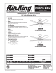
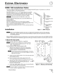
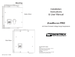
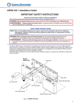
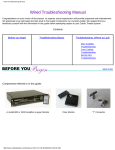
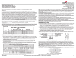
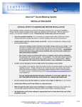
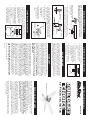
BLADE ASSEMBLY AND
Remove
Remove
NOTE: The blades should be attached to the fan after it is
hung and wired to prevent blade brackets from being bent
and causing the fan to wobble.
Remove the three shipping
stabilizer tabs from the
bottom of the fan.
1.
Blade Bracket
Using three phillips washer head screws, secure one
bracket to each of the blades. Complete this assembly
before attaching blades to ceiling fan. (Figure 6)
Phillips Washer
Head Screw
Blade
Screws
2.
Place one of the phillips pan head screws into one of the
recessed holes in the blade bracket. Turn screw until it
mates with threaded hole in hub. Do not tighten screw
completely at this time. (Figure 7)
Figure 6
3.
Install the second screw
in the same manner,
then tighten both
screws firmly.
Motor Hub
4.
Phillips Pan
Head Screw
Connect the black wire in the light fitter with the blue wire
marked “For Light” using the supplied wire nuts. (Figure 8)
Blade
Bracket
Install the remaining
blade assemblies by
repeating the above
steps.
Figure 7
1.
LIGHT KIT INSTALLATION
2.
Connect the white wire in the
light fitter with the white wire
marked “For Light” using the
supplied wire nuts.
Black
Figure 8
Light
Fitter
White
Wires
Scre
3.
Tuck the wires and wire nuts into Wire
switch cup. Lift the light fitter
into place and insert the three
Globe
screws and tighten.
Blue
Wire
4.
Install light bulb (not included)
and lift globe into place and
secure with the three thumb
screws. Do not overtighten.
2.
1.
Check the operation of the fan
by gently pulling the chain
switch.
Restore power to the electrical box.
Reversing Switch
USING YOUR CEILING FAN
3.
To reverse airflow direction, turn
fan off and wait for the blades
to come to a full stop, then slide
reversing switch to opposite
position. (Figure 9)
Figure 9
4.
Your ceiling fan is equipped
with four position, three speed
pull chain switch.
MAINTENANCE
Periodic cleaning of your ceiling fan is the only maintenance
that is needed. When cleaning, use only a soft brush or lint
free cloth to avoid scratching the finish. Abrasive cleaning
agents are not required and should be avoided to prevent
damage to the finish. Do not spray water directly onto your
ceiling fan. It could damage the motor or the blades and create
the possibility of an electrical shock or fire.
WARRANTY
The ceiling fan you have purchased is warranted by the
manufacturer for one year from the date of purchase against
defects in workmanship and/or materials. The motor is
warranted for ten years. This warranty means that only the
parts that prove to be defective during the period of warranty
will be either repaired or replaced at our option. The right is
reserved by the manufacturer to replace the whole product
in lieu thereof. Should repair become necessary during the
warranty period, write to: AIR KING c/o LASKO PRODUCTS,
INC., Appliance Service Department, 820 Lincoln Ave., West
Chester, PA 19380. Describe the problem you are having. DO
NOT SEND FAN!
This warranty does not apply if the damage occurs because
of accident, improper handling, installation or operation,
shipping damage, abuse, misuse or unauthorized repairs made
or attempted. ALL WARRANTIES, EXPRESSED OR IMPLIED
LAST FOR ONE YEAR FROM DATE OF ORIGINAL PURCHASE,
EXCEPT FOR THE MOTOR. THIS WARRANTY DOES NOT
COVER LIABILITY FOR INCIDENTAL OR CONSEQUENTIAL
DAMAGES FOR ANY CAUSE WHATSOEVER. Some states do
not allow limitations on how long any implied warranty lasts,
or the exclusion or limitations of incidental or consequential
damages, so that the above limitation or exclusion may not
apply to you. This warranty gives you specific legal rights,
and you may have other rights that vary from state to state.
FOR REPLACEMENT PARTS: Please call 1-800-966-2028,
Monday - Friday, between the hours of 8am and 4 pm EST.
Reference the type and style of product when you call.
FOR QUESTIONS OR COMMENTS ABOUT YOUR CEILING
FAN: Please call 1-800-233-0268, Monday - Friday, between
the hours of 8am and 4pm EST.
New 11/00
INSTRUCTION MANUAL
Model 9898L
52" PORCH CEILING FAN
READ AND SAVE THESE
Your new ceiling fan is UL listed and will require a grounded
electrical supply line of 120 volts AC, 60 Hz, 15 amp circuit.
The 52" total fan weight is 26 lbs maximum.
WARNING: To reduce the risk of fire, electrical shock or
personal injury, mount fan at least 7 feet above the floor to
an outlet box marked “Acceptable for fan support.” Use
screws provided with outlet box. Most outlet boxes commonly
used for the support of lighting fixtures are not acceptable
for fan support and may need to be replaced. Consult a
qualified electrician if in doubt.
Your ceiling fan will fit any of the following electrical boxes:
4" octagon box, 3" octagon box, 1/2" deep ceiling pan, or a
plaster ring with 3 1/2" mounting hole centers mounted on
one of the above listed boxes. Your new fan will also install
on a “wiremold” No. 5738 fixture box. The electrical box must
be securely anchored an capable of withstanding a load of at
least 50 pounds.
If your ceiling fan does not have one of the above electrical
boxes for proper wiring, you may wish to contact a licensed
electrician for installation.
RULES FOR SAFE INSTALLATION
1. Follow the recommended instructions for the proper
method of wiring your ceiling fan. If you do not know
enough about electrical wiring, have your fan installed by
a licensed electrician.
2. All wiring must satisfy National and Local electrical codes.
The ceiling fan must be grounded as a precaution against
possible electrical shock.
3. The electrical outlet box and joist must be securely mounted
and capable of reliably supporting at least 50 pounds.
4. WARNING: To reduce the risk of fire, electrical shock
and/or personal injury:
a) Be sure electricity is turned off at the main fuse box
before wiring, cleaning or servicing.
b) Fan should not be mounted in areas where it might
come in direct contact with water.
RULES FOR SAFE OPERATION
1. Be careful of the fan and moving blades when cleaning,
painting or working near fan.
2. Do not put anything into the blades while they are turning.
3. Do not bend the blade brackets when installing the brackets,
balancing the blades or cleaning the fan.
INSTALLATION INSTRUCTIONS
4. WARNING: The fan must be hung with at least 7 feet of
clearance from floor to blades.
1.
Attach the hanger bracket to the electrical box capable of
reliably supporting at least 50 pounds. Insert the screws
through the slotted holes in the bracket and attach to the
electrical box. Tighten both screws to the electrical box.
(Figure 1)
Electrical Box
Screw
Figure 1
Mounting
Bracket
NOTE: If bracket and/or electrical box are not securely
attached, the fan could wobble.
2.
Install motor leads through the canopy then through the
hole in the center of the pipe flange. Insert downrod into
downrod yoke. Make sure to align hole in downrod with
hole in downrod yoke. Lift canopy and install yoke cross
pin through yoke and downrod. Insert cotter pin into cross
pin until it snaps into place. Using a phillips head
screwdriver firmly tighten set screws in yoke. (Figure 2)
Cotter Pin
Set Screw
Yoke Cross Pin
Canopy
WARNING: Failure to completely install the cotter pin or
tighten the set screw could result in the fan loosening and
possibly falling.
Pipe Flange
Cotter Pin
Figure 2
3.
Carefully lift the fan and seat the pipe flange and ball
assembly on the hanger bracket that was just attached to
the electrical box. Be sure the notch on the side of the ball
is lined up with tab on the hanger bracket. (Figure 3)
WARNING: Failure to seat tab on bracket into notch on ball
could cause damage to electrical wires and cause fan to fall.
Electrical Box
NOTE: Do not pinch wires between the ball and pipe flange
assembly and hanger bracket.
NOTE: Ceiling canopy
supply wires and fan wires
omitted from figure for
clarity
Pipe Flange
Assembly
4.
Make sure the electrical box is properly secured. If romex
cable (plastic sheathed) was used to wire the electrical
box, the presence of a third wire connected to the electrical
box indicates that the box is grounded. This ground wire
may be bare wire (no insulating jacket), or a green insulated
wire. The two supply wires will be white and black insulated
wires.
Figure 3
5.
If the wiring to the electrical box is enclosed in electrical
conduit pipe, the ground wire may not be present. The
conduit itself could serve as the ground.
GROUNDING:
6. Romex (plastic sheathed) Cable: If romex cable was used
to wire the electric box, connect the green ground wire
attached to the hanger ball and the green ground wire in
the Romex cable using a 72B listed wire nut.
6a. Conduit Pipe: If the wiring to the electrical box is enclosed
in electrical conduit pipe, connect the ground wire to the
ground screw in the electrical box.
7.
Black Supply
(Hot)
White Fan
(Neutral)
White Supply
(Neutral)
Electrical Supply: Connect the fan motor white wire to the
supply white (Neutral) wire using a listed wire nut. Connect
the fan motor black wire and blue wire to the supply black
(hot) wire using a listed wire nut. Your fan is now wired
to be turned on and off from the fan (pull chain) switch.
(Figure 2) With wire nuts turned upward, place green and
white connections to one side of box and blue and black
connections towards the other side and push carefully up
into outlet box.
Supply Ground
Green or Bare
Green Jumper
Wire
Black Fan
(Hot)
Figure 4
NOTE: Check to see that all connections are tight, including
the ground and that no bare wire is visible at the wire nuts,
except for the ground wire.
8.
Raise canopy up to mounting bracket and fit screws into
slots on canopy and rotate to the left to lock into place.
Tighten both screws. (Figure 5)
Canopy
Mounting
Bracket
NOTE: Make sure that the electrical wires are completely
inside the electrical box and not pinched between the ceiling
canopy and the ceiling.
Scre
Figure 5