1
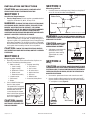
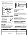
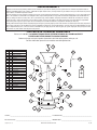
IMPORTANT INSTRUCTIONS OPERATING MANUAL
Models: 9848, 9856,
9856UF
Ceiling Fan
READ AND SAVE THESE INSTRUCTIONS
READ CAREFULLY BEFORE ATTEMPTING TO ASSEMBLE, INSTALL, OPERATE OR MAINTAIN THE PRODUCT DESCRIBED.
PROTECT YOURSELF AND OTHERS BY OBSERVING ALL SAFETY INFORMATION. FAILURE TO COMPLY WITH
INSTRUCTIONS COULD RESULT IN PERSONAL INJURY AND/OR PROPERTY DAMAGE!
RETAIN INSTRUCTIONS FOR FUTURE REFERENCE.
GENERAL SAFETY INFORMATION
When using electrical appliances, basic precautions
should always be followed to reduce the risk of fire,
electric shock and injury to person, including the following:
WARNING: TO REDUCE THE RISK OF FIRE, ELECTRIC SHOCK
7.
AND INJURY TO PERSON, OBSERVE THE FOLLOWING:
WARNING: TO REDUCE THE RISK OF PERSONAL INJURY,
1.
Read all instructions before installing or using fan.
2.
Use this unit only in the manner intended by the manufacturer.
If you have questions, contact the manufacturer.
3.
Before servicing or cleaning the unit, switch power off at service
panel and lock the service disconnecting means to prevent
power from being switched on accidentally. When the service
disconnecting means cannot be locked, securely fasten a
prominent warning device, such as a tag, to the service panel.
4.
Completely reassemble fan according to instructions before
reconnecting to power supply.
Installation work and electrical wiring must be done by qualified
person(s) in accordance with all applicable codes and standards,
including fire-related construction.
CAUTION: THIS FAN MUST NOT BE USED IN POTENTIALLY
DANGEROUS LOCATIONS SUCH AS FLAMMABLE, EXPLOSIVE,
CHEMICAL-LADEN OR WET ATMOSPHERES.
5.
Make certain that the power source conforms to the electrical
requirements of the fan.
6.
The fan must be hung with at least 10 feet of clearance from the
floor to the blades.
DO NOT BEND THE BLADE BRACKETS OR BLADES WHEN
INSTALLING THE BLADES, BALANCING THE BLADES, OR CLEANING
THE FAN. DO NOT INSERT FOREIGN OBLECTS IN BETWEEN THE
ROTATING FAN BLADES.
8.
This fan is not for use in wet or damp locations.
9.
Do not use fan outdoors and never locate the fan where it may
fall into a bathtub or other water container.
10. This unit must be grounded.
11. To avoid motor bearing damage and noisy and/or unbalanced
impellers, keep drywall spray, construction dust, etc. off power
unit.
WARNING: TO REDUCE THE RISK OF FIRE, ELECTRIC SHOCK,
DO NOT USE THIS FAN WITH ANY SOLID-STATE SPEED CONTROL
DEVICE.
SAVE THESE INSTRUCTIONS
984856 Rev B. 7-07
www.airkinglimited.com
1 of 4
INSTALLATION INSTRUCTIONS
SECTION 3
CAUTION: MAKE SURE POWER IS SWITCHED OFF AT
Mounting the Fan
2. Carefully lift the fan and hang on the J-Hook, ensuring that all
wires are clear of the rubber roller (Figure 2).
SERVICE PANEL BEFORE STARTING INSTALLATION.
SECTION 1
Installation Requirements
1. Electrical Requirements: This unit requires a grounded electrical
supply line of 120 volts AC, 60 Hz, 15 amp circuit.
Rubber Roller
WARNING: TO REDUCE THE RISK OF FIRE, ELECTRIC SHOCK,
Downrod
OR PERSONAL INJURY, PROPERLY INSTALL TO AN OUTLET BOX
MARKED “ACCEPTABLE FOR FAN SUPPORT”. USE SCREWS
PROVIDED WITH OUTLET BOX. MOST OUTLET BOXES COMMONLY
USED FOR THE SUPPORT OF LIGHTING FIXTURES ARE NOT
ACCEPTABLE FOR FAN SUPPORT AND MAY NEED TO BE REPLACED.
CONSULT A QUALIFIED ELECTRICIAN IF IN DOUBT.
2.
Electrical Box: This unit will fit any of the following electrical
boxes: 4" octagon box, 3" octagon box, 1/2" deep ceiling pan, or
a plaster ring with 3-1/2" mounting hole centers mounted on one
of the above listed boxes. This fan will also install on a “Wiremold”
No. 5738 fixture box. The electrical box must be securely anchored
and capable of withstanding a load of at least 35 pounds.
CAUTION: IF ONE OF THE ABOVE ELECTRICAL BOXES IS
Upper Canopy
Figure 2
J-HOOK BRACKET COULD CAUSE DAMAGE TO ELECTRICAL WIRES
AND CAUSE FAN TO FALL.
CAUTION: DO NOT PINCH
2.
1 - Package containing:
4 - Flat washers
2 - 8/32" screws
2 - #8 lock washers
2 - #10 lock washers
3 - Wire nuts
2 - Wood screws
1 - Instruction/Safety Sheet
Install J-Hook Bracket to an
Electrical Box
electrical box marked
“Acceptable For Fan Support”
using the screws provided with
the outlet box. Insert the
screws through the slotted
holes in the bracket and attach
to the electrical box. Tighten
both screws (Figure 1).
CAUTION: IF BRACKET
Screw
AND/OR ELECTRICAL BOX ARE
NOT SECURELY ATTACHED, THE
FAN COULD WOBBLE.
Figure 1
984856 Rev B. 7-07
NOTE: Wires omitted
from figure for clarity
WIRES BETWEEN THE J-HOOK
AND DOWNROD ASSEMBLY.
2.
SECTION 2
1 - Motor assembly
1 - Lower canopy
1 - Upper canopy
6 - Blade lock washers
6 - Blade screws
1 - Downrod assembly
1 - J-hook bracket
1 - Wall control
3 - Blades
NOTE: Wires omitted from figure for clarity
WARNING: FAILURE TO SEAT DOWNROD ASSEMBLY ON
NOT PRESENT FOR PROPER INSTALLATION, CONTACT A LICENSED
ELECTRICIAN.
Preparing the Ceiling Fan
1. Unpack fan from the carton and confirm that all pieces are
present. The following should be present:
J-Hook Bracket
Slide lower canopy down the
downrod until it is snug
against the motor housing.
Tighten both set screws
(Figure 3).
SECTION 4
Wiring
Lower
Canopy
Screw
Figure 3
CAUTION: ALL ELECTRICAL CONNECTIONS MUST BE MADE
IN ACCORDANCE WITH LOCAL CODES, ORDINANCES, OR NATIONAL
ELECTRICAL CODE. IF YOU ARE UNFAMILIAR WITH METHODS OF
INSTALLING ELECTRICAL WIRING, SECURE THE SERVICES OF A
QUALIFIED ELECTRICIAN.
1. Unscrew the speed control cover and screw base to wall.
2.
Connect the Black (Hot) supply wire into socket marked “A”.
Connect the Black lead wire from the fan into socket marked
“F” and tighten screws (Figure 4).
F A
J-Hook
Bracket
Wall Control
Figure 4
www.airkinglimited.com
2 of 4
3.
Replace the front cover of the switch control box with the
supplied screws and tighten.
4.
Make sure the electrical box is properly secured. Connect the
White wire from the fan to the White wire from the supply.
Connect the Black wire from the fan to the Black (hot) wire from
the wall switch. Connect the Green or Bare Copper ground wire
from the house to the Green wire from the fan. Use approved
methods for all connections and carefully push wires up into
the outlet box (Figure 5).
Ground
1.
Blade
Supply from home
Figure 7
White
Hot (Black)
2.
3.
Hot (Black)
White
ARE TIGHT, INCLUDING THE GROUND, AND THAT NO BARE WIRE
IS VISIBLE AT THE CONNECTIONS, EXCEPT IN THE CASE THAT A
BARE WIRE WAS USED FOR THE GROUND WIRE.
Operation
1. Restore electrical power to the wall switch by turning the
electricity on at the main fuse box.
2. Check the operation of the fan by selecting a speed on wall switch.
SECTION 11
Maintenance and Cleaning
CAUTION: MAKE SURE POWER IS SWITCHED OFF AT
SERVICE PANEL BEFORE SERVICING THE UNIT.
Slide upper canopy up the
downrod until it is snug
against the ceiling. Tighten
both set screws. (Figure 6).
Electrical Box
WARNING: DO NOT DEPEND UPON THE FAN’S CONTROLS
AS THE SOLE MEANS OF DISCONNECTING POWER WHEN
INSTALLING OR SERVICING THE FAN. ALWAYS TURN POWER OFF
AT THE MAIN FUSE BOX.
CAUTION: MAKE SURE
THAT THE ELECTRICAL WIRES
ARE COMPLETELY INSIDE THE
ELECTRICAL BOX AND NOT
PINCHED BETWEEN THE CEILING
CANOPY AND THE CEILING.
SECTION 5
Install second screw in the same manner, then tighten both
screws fully.
Repeat steps 1 and 2 for the 2 remaining blades.
NOTE: Model 9856UF is a single speed that directs the airflow upwards.
from fan
CAUTION: CHECK TO CONFIRM THAT ALL CONNECTIONS
5.
Screw, Spring Washer,
Paper Washer
SECTION 10
Ground
Figure 5
Insert one screw through the spring washer, paper washer and
into the motor hub. Do not tighten fully at this time (Figure 7).
WARNING: DO NOT USE WATER WHEN CLEANING. IT
Upper
Canopy
COULD DAMAGE THE MOTOR OR BLADES AND CREATE THE
POSSIBILITY OF AN ELECTRICAL SHOCK OR FIRE.
Screw
Figure 6
NOTE: Wires omitted
from figure for clarity
Installing the Blades
CAUTION: DO NOT USE GASOLINE, BENZINE, THINNER,
HARSH CLEANSERS, ETC., AS THEY MAY DAMAGE THE FAN.
1.
Use only a soft brush or lint free cloth to avoid scratching the
finish. Abrasive cleaning agents are not required and should be
avoided to prevent damage to the finish. NEVER USE ANY
ABRASIVE PADS OR SCOURING POWDERS. NEVER IMMERSE
ELECTRICAL PARTS IN WATER.
2.
The fan is permanently lubricated and does not require oiling.
CAUTION: THE BLADES SHOULD BE ATTACHED TO THE
FAN MOTOR AFTER IT IS HUNG AND WIRED. IF THE BLADES ARE
ATTACHED WHILE THE MOTOR IS ON THE FLOOR, THE BLADES
COULD GET BENT, CAUSING THE FAN TO WOBBLE.
Troubleshooting Guide
Trouble
Probable Cause
Suggested Remedy
1.
Fan will not start
1. Fuse or circuit breaker blown or OFF.
2. Loose power connections.
3. Wall Control in the off position.
1. Check main and branch fuse or circuit breaker.
2. Check line wire connections to the fan.
3. Turn wall control to desired setting.
2.
Fan sounds noisy
1. Screws securing fan blades to motor housing are loose.
2. Wire nuts inside electrical box are rattling.
1. Check to be sure screws are tight.
2. Check wire nut connections in electrical box.
3.
Fan wobbles or shakes excessively
1. Screws securing fan blade brackets to motor housing are loose.
2. Fan blades not seated properly
3. Fan blades out of balance.
1. Check to be sure screws are tight.
2. Check that blades are seated firmly to top of motor housing.
3. Interchanging adjacent (side-by-side) blade pairs can redistribute the
weight and result in smoother operation.
984856 Rev B. 7-07
www.airkinglimited.com
3 of 4
LIMITED WARRANTY
All products manufactured by Air King Limited are warranted for one year from the date of purchase against defects in workmanship and/or material. In
addition, all ventilating/exhaust fans, heaters, combination fan lights and/or heaters, and range hoods are guaranteed for five years from the date of purchase
against defects in workmanship and/or material.
This warranty does not cover any labor or shipping costs or the cost of replacement components as part of routine maintenance such as: range hood grease
filters, charcoal filters or combination charcoal/grease filters; replacement light bulbs in range hoods or bathroom fan/light/bulb heater combinations. As
well, any damage or failure caused by abuse, misuse, abnormal usage, faulty installation, or improper maintenance will not be covered by this warranty.
In order to make a claim on this warranty, you must be the original consumer of the product. You will be required to present to Air King the original bill of
sale showing: date of purchase, place of purchase and model purchased. Failure to meet these requirements will void your warranty.
Air King will not be held responsible for any bodily injury or damages to personal property or real estate whether caused directly or indirectly by the product.
Some states and provinces do not allow the exclusion or limitation of incidental or consequential damages and some states do not allow limitations on how
long an implied warranty lasts, so these exclusions or limitations may not apply to you. This warranty gives you specific legal rights and you may have other
rights which vary from state to state and province to province.
FOR PARTS OR TECHNICAL ASSISTANCE
Please call: 1-800-465-7300, MONDAY THROUGH FRIDAY, BETWEEN THE HOURS OF 8 AM AND 4:00 PM EST.
PLEASE DO NOT RETURN PRODUCT TO PLACE OF PURCHASE.
Reference the type and style of product (located on label inside of the product) when you call.
For more information please visit our website: wwwairkinglimited.com
1
#
1
2
3
4
5
6
7
8
9
10
11
12
13
14
15
16
17
18
19
20
21
22
23
Qty.
1
1
4
1
4
1
3
3
1
3
1
6
6
3
3
1
1
1
1
1
1
1
1
Description
J-Hook Bracket
Upper Canopy
Canopy Set Screw
Cross Pin
Cotter Pin
Rubber Roller
Hex Nut
Lock Washer
Upper Downrod Bracket
Mounting Bracket Bolt
Downrod
Blade Screws
Blade Lock Washer
Paper Washer
Blade
Lower Canopy
Lower Downrod Bracket
Capacitor
Capicitor Mounting Screw
Motor
Ground Wire
Ground Wire Screw
Wall Control
21
2
3
22
4
5
23
6
9
7
8
11
10
12
13
14
16
3
10
5
15
18
17
19
7
20
8
Installer: _________________________________________________________ Installation Date:_________________________________________
Place of Purchase: _________________________________________________ Model Number: __________________________________________
984856 Rev B. 7-07
www.airkinglimited.com
4 of 4