1
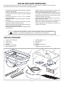
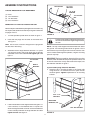
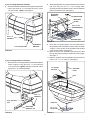
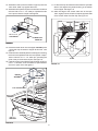
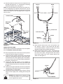
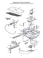
™
OWNERS
MANUAL
Model No.
45-0324
ATV MOUNTED
125 LB. BROADCAST SPREADER
CAUTION:
Read Rules for
Safe Operation
and Instructions
Carefully
•
•
•
•
Assembly
Operation
Maintenance
Repair Parts
the fastest way to purchase parts www.speedepart.com
PRINTED IN USA
FORM NO. 48581 (REV. 3/06)
RULES FOR SAFE OPERATION
Any power equipment can cause injury if operated improperly or if the user does not understand how to operate
the equipment. Exercise caution at all times when operating equipment.
•
•
•
•
•
•
•
•
Read this owners manual before attempting to assemble
or operate the spreader.
Read the vehicle owners manual and know how
to operate your vehicle, before using the spreader
attachment.
Do not allow anyone to ride on or sit on spreader
attachment frame.
Never allow children to operate the vehicle or spreader
attachment.
Do not allow adults to operate the vehicle or spreader
attachment without proper instructions.
Never operate vehicle and spreader attachment without
wearing solid, substantial footwear.
Wear eye and hand protection when handling and using
lawn chemicals.
•
•
•
•
Always begin with the transmission in first (low) and
gradually increase speed as conditions permit.
When using broadcast spreader do not drive too close
to a creek or ditch and be alert for holes and other
hazards which could cause you to loose control of the
broadcast spreader and vehicle.
Always operate vehicle and spreader up and down a
slope, never across a slope.
Read instructions and caution notes for handling and
application of materials purchased for spreading.
Follow maintenance and lubrication instructions as
outlined in this manual.
LOOK FOR THIS SYMBOL TO POINT OUT IMPORTANT SAFETY PRECAUTIONS. IT
MEANS — ATTENTION! BECOME ALERT! YOUR SAFETY IS INVOLVED.
CARTON CONTENTS
1.
2.
3.
4.
5.
6.
7.
8.
9.
10.
11.
Hopper/Frame Assembly
Vinyl Cover
Impeller Shaft
Impeller
Motor Mount Assembly
Mounting Bracket, R.H.
Mounting Bracket, L.H.
Wire Harness
Deflector
Extension Brackets (2)
Screen
Hardware Package (See page 3)
2
1
3
4
5
8
6
7
10
9
11
2
HARDWARE PACKAGE
SHOWN FULL SIZE
A
B
D
C
F
E
H
G
K
J
I
L
NOT SHOWN FULL SIZE
M
N
R
KEY
A
B
C
D
E
F
G
H
I
J
K
QTY.
4
8
2
1
5
4
12
2
4
4
1
P
O
T
S
DESCRIPTION
Hex Bolt, 5/16" x 2"
Hex Bolt, 5/16" x 1"
Hex Bolt, 1/4" x 3/4"
Carriage, 5/16" x 1"
Carriage Bolt, 5/16" x 1-3/4"
Nylock Hex Nut, 1/4"
Nylock Hex Nut, 5/16"
Flat Washer , 1/4"
Flat Washer, 5/16"
Nylon Washer
Hair Pin Agitator
3
KEY
QTY.
L
M
N
O
P
Q
R
S
T
3
1
2
4
2
1
5
2
5
DESCRIPTION
Cotter Pin, 1/8" x 1-1/4"
Coupler
Seal
Adhesive Pad
Plug
Nylon Tie
Plastic Knob
Angle Bracket
Mounting Clamp
Q
ASSEMBLY INSTRUCTIONS
DEFLECTOR
TOOLS REQUIRED FOR ASSEMBLY
(1)
(2)
(2)
(2)
1/4" x 3/4"
HEX BOLT
1/4" FLAT
WASHER
Pliers
7/16" Wrenches
1/2" Wrenches
9/16" Wrenches
1/4" NYLOCK
NUT
REMOVAL OF PARTS FROM CARTON
Remove all parts and hardware packages from the carton. Lay
out all parts and hardware and identify using the illustrations
on pages 2 and 3.
FIGURE 2
1. Turn the spreader upside down as shown in figure 1.
Position the spreader for adequate clearance if
the vehicle muffler discharges straight toward
the rear.
2. Press the two plugs into the ends of the frame tube.
See figure 1.
HINT: Use a block of wood to help press the plug down
into the end of the tubing.
NOTE: The top of the hopper should be at least 30" above
the ground. The mounting holes shown in figures 3 and 4
will make the top of the hopper even with the vehicle's rear
rack. If exhaust blows against spreader, a higher mounting
position may help.
3. Assemble the two angle brackets and two 1/4" nylock
nuts onto the ends of the longer bolts that are already
assemble to the frame tube. Do not tighten yet. See
figure 1.
IMPORTANT: Before proceeding, determine if the mounting
brackets, when attached directly to the spreader frame, will
fit onto the vehicle rack. If they need to be farther apart, use
the extension brackets in figure 4.
1/4" NYLOCK
NUT
ANGLE
BRACKET
If you are NOT using extension brackets:
5. Attach the R.H. mounting bracket to the frame tube
using two 5/16" x 2" hex bolts and 5/16" nylock nuts as
shown in figure 3. Tighten. Repeat for the L.H. mounting
bracket.
PLUG
5/16" x 1-2"
HEX BOLT
FIGURE 1
MOUNTING
BRACKET, R.H.
4. Fasten the deflector to the angle brackets using two 1/4"
x 3/4" hex bolts, 1/4" flat washers and 1/4" nylock nuts.
Allow the angle brackets to swivel so that the deflector
curves naturally between the angle brackets and then
tighten all nuts. See figure 2.
5/16" NYLOCK NUT
FIGURE 3
4
If you are using extension brackets:
6. Attach the extension brackets to the legs of the spreader
frame. Use two 5/16" x 2" hex bolts and 5/16" nylock
nuts per bracket. Tighten. See figure 4.
8. Attach the spreader's mounting brackets to the vehicle's
rear rack using four 5/16" x 1-3/4" carriage bolts,
mounting clamps and plastic knobs. Use the adhesive
pads to protect the rack. See figure 6.
MOUNTING
BRACKET
PLASTIC KNOB
MOUNTING
CLAMP
5/16" x 1-3/4"
CARRIAGE BOLT
5/16" x 2"
HEX BOLT
ADHESIVE PAD
FIGURE 6
5/16" NYLOCK NUT
9. Insert the 1/8" hairpin agitator into the middle hole in
the spreader shaft. Assemble a seal (turned as shown
in figure 7) onto the end of the spreader shaft closest
to the hairpin agitator. See figure 7.
10. Slide the end of the spreader shaft having the seal
through the plastic bushing in the bottom of the hopper.
See figure 7.
11. Slide the impeller onto the spreader shaft and secure
it with a 1/8" x 1-1/4" cotter pin. See figure 7.
EXTENSION
BRACKET
FIGURE 4
If you are using extension brackets:
7. Attach the R.H. mounting bracket to the extension bracket
shown in figure 5 using two 5/16" x 1" hex bolts and
5/16" nylock nuts. Tighten. Repeat on the other frame
leg with the L.H. mounting bracket.
1/8" HAIRPIN
AGITATOR
SPREADER
SHAFT
SEAL
5/16" x 1"
HEX BOLT
5/16" NYLOCK
NUT
IMPELLER
MOUNTING
BRACKET, R.H.
1/8" x 1-1/4"
COTTER PIN
FIGURE 5
5
FIGURE 7
12. Assemble a seal (turned as shown in figure 8) onto the
motor shaft. Slide it up against the motor.
13. Assemble the impeller coupler onto the motor shaft and
secure it with a 1/8" x 1-1/4" cotter pin. Spread the ends
of the pin around the coupler. See figure 8.
17. Lift the screen up and slide the seal down the spreader
shaft to rest against the plastic bushing in the bottom
of the hopper. See figure 10.
18. Slide one edge of the screen under one of the clips.
Then, slightly bow the screen to slide the opposite side
of the screen under the other clip. See figure 10.
CLIP
SCREEN
SHAFT
SEAL
BUSHING
SEAL
1/8" x 1-1/4"
COTTER PIN
IMPELLER
COUPLER
FIGURE 8
14. Place the screen down into the hopper. DO NOT place
it under the clips in bottom of hopper at this time. See
figure 9.
15. Place the motor assembly down into the hopper, inserting
the end of the spreader shaft into the impeller coupler.
Secure it with a 1/8" x 1-1/4" cotter pin, spreading the
ends of the pin around the coupler. See figure 9.
16. Fasten the motor mount bracket to the hopper using four
5/16" x 1" hex bolts, 5/16" flat washers, nylon washers
and 5/16" nylock nuts. See figure 9.
MOTOR
ASSEMBLY
CLIPS
FIGURE 10
1/8" x 1-1/4"
COTTER PIN
5/16" NYLOCK NUT
SPREADER
SHAFT
5/16" FLAT
WASHER
NYLON
WASHER
SCREEN
5/16" x 1"
HEX BOLT
FIGURE 9
6
19. Attach the flow control to the motor mount bracket on the
spreader using the 5/16" x 1" carriage bolt, a mounting
clamp and a plastic knob. See figure 11.
NOTE: You can also attach to the rear rack if you use a 5/16"
x 1-3/4" carriage bolt. If you attach to the rear rack, you can
loosely pre-assemble the clamp, bolt and knob to the flow
control. The clamp can then be angled down through the
slot in the rack.
MOTOR
SWITCH
RED
BROWN
WHITE
PLASTIC KNOB
MOUNTING
CLAMP
RED
BROWN
5/16" x 1"
CARRIAGE
BOLT
NEGATIVE PIN
5/16" x 1-3/4"
CARRIAGE
BOLT
FUSE AND HOLDER
RED
BROWN
POSITIVE
"HOT" POST
+
BATTERY
FIGURE 12
25. Move the flow control lever to the "ON" position. Flip
the "ON-OFF" switch on and check that the motor
runs counterclockwise. If it does not, refer to the wiring
diagram on page 6 and recheck the hookup.
26. Move the flow control lever to "OFF". This should turn
the "ON-OFF" switch off. If it does not, you can loosen
the control and rotate it enough that the flow control
lever, when moved to the "OFF" position will turn the
switch off. See figure 13.
FIGURE 11
WIRING INSTRUCTIONS
When properly connected, the spreader motor and impeller
will run clockwise viewed from above.
20. Move the spreader's flow control lever to the off position
so that the "ON-Off" switch is turned off.
21. Connect the short (fused) wire harness to the vehicle
battery by connecting the red wire to the positive post
and the brown wire to the negative post on the battery.
The wire harness may be left permanently attached to
the battery. See figure 12.
22. Connect the long wire harness to the spreader by
connecting the red and white wires to the switch and
the brown and white wires to the spreader motor. Refer
to figure 12.
23. Connect the long wire harness to the short (fused) wire
harness. Be sure the wires are clear of any moving parts,
hot engine parts, or pinch points.
24. Use the nylon ties provided to safely secure the wiring
away from hot engine parts, rotating parts and pinch
points.
ON-OFF
"ON-OFF"
SWITCH
NEVER allow negative pin on plug to come
in contact with positive "hot" post on battery.
Fire or explosion can result!
FLOW CONTROL
FIGURE 13
7
OPERATION
8. Shut the closure plate before turning or stopping.
9. To insure uniform coverage, make each pass so that the
broadcast pattern slightly overlaps the pattern from the
previous pass as shown in figure 15. The approximate
broadcast widths for different materials are shown in
the application chart on this page.
10. When broadcasting weed control fertilizers, make sure
the broadcast pattern does not hit evergreen trees,
flowers or shrubs.
11. Heavy moisture conditions may require a cover over the
hopper to keep contents dry. The vinyl cover acts as a
wind and moisture shield, but should not be used as a
rain cover.
12. If fertilizer is accidentally deposited too heavily in an
area, soak the area thoroughly with a garden hose or
sprinkler to prevent burning of the lawn.
HOW TO USE YOUR SPREADER
SETTING THE FLOW CONTROL
1. Slide the Adjustable stop to the desired setting.
2. Move the Flow Control Lever forward until it snaps into
the Adjustable Stop, locking the lever at the desired
setting. See figure 14.
FLOW CONTROL LEVER
3
1
OF
F
ADJUSTABLE STOP
7
5
10
REFER
TO CHART
FIGURE 14
STARTING THE SPREADER
1. Move the Flow Control Lever against the Adjustable
Stop and flip the "ON-OFF" switch to the on position.
OVERLAP
STOPPING THE SPREADER
1. Move the Flow Control Lever to the "OFF" position. Make
sure that the switch is turned off by the Flow Control
Lever.
FIGURE 15
USING YOUR SPREADER
IMPORTANT: Application rates shown in the chart are
affected by humidity and by the moisture content of
the material (granular and pellet). Some minor setting
adjustments may be necessary to compensate for this
condition.
We do not recommend the use of any powdered lawn
chemicals, due to difficulty in obtaining a satisfactory or
consistent broadcast pattern.
1. Determine approximate square footage of area to be
covered and estimate amount of material required.
2. Verify that the spreader motor turns on and off and that
the flow control is operating properly.
3. Make sure the flow control lever is in the off position
and the closure plate is shut.
4. Set the adjustable stop to the desired flow rate, keeping
the flow control arm in the off position. Refer to the
application chart on this page and the instructions
on the fertilizer bag to determine the proper flow rate
setting. The application chart is calculated for a vehicle
speed of 3 mph (100 ft. in 23 seconds). Faster speeds
require higher flow rate settings to maintain the same
application rate.
5. Fill the hopper with the material to be spread, breaking
up any lumps as you fill the hopper.
7. Start the vehicle in motion and then open the spreader
closure plate and flip the switch to "ON".
APPLICATION CHART
TYPE
MATERIAL
FERTILIZER
Powder
Granular
Pelleted
Organic
GRASS SEED
Fine
Coarse
ICE MELTER
SAND
FLOW SETTING
3 MPH
SPREAD
WIDTH
3-5
3-5
3-5
6-8
3' - 4'
10' - 12'
17' - 19'
3' - 4'
3-4
4-5
6-8
4-10
3' - 4'
8' - 9'
17' - 19'
17' - 19'
OPERATING SPEED - 3 MPH. (100 ft. in 23 seconds)
8
MAINTENANCE
REMOVING THE SPREADER
13. Disconnect the spreader from the vehicle battery by
unplugging the short wire harness from the long wire
harness.The short wire harness may be left permanently
attached to the battery.
14. Remove the flow control from the rear rack of the vehicle
if it is attached there.
15. Loosen the knobs on the spreader mounting brackets.
Rotate the clamps fastened underneath the vehicle
rack and lift them up through the rack to remove the
spreader.
CHECK FOR LOOSE FASTENERS
1. Before each use make a thorough visual check of the
spreader for any bolts and nuts which may have loosened.
Retighten any loose bolts and nuts.
CHECK FOR WORN OF DAMAGED PARTS
2. Check for worn or damaged parts before each use.
Repair or replace parts if necessary.
CLEANING
3. Rinse inside of hopper and exterior of spreader and dry
off before storing.
STORAGE
1. Rinse inside of hopper and exterior of spreader and dry
off before storing.
2. Store in a clean, dry area.
TROUBLE SHOOTING POINTS
Hopper closure plate does not open to
the correct position.
1. Material packed around plate
1. Clean out around closure plate
Spreader motor doesn't run.
1. Loose connection in spreader
wiring
2. In line fuse is blown.
3. Loose battery connection
4. Battery is run down.
5. Broken spreader wiring
6. Spreader switch is broken.
7. Spreader motor is broken.
1.
2.
3.
4.
5.
6.
7.
Spreader motor runs backwards.
1. Wired backwards to battery.
1. Switch wiring at battery terminals.
Motor runs when switch is shut off.
1. Wired backwards to battery.
2. Spreader on-off switch is broken.
1. Switch wiring at battery terminals.
2. Replace the switch.
9
Check and reconnect.
Replace fuse.
Tighten battery terminals.
Recharge the battery.
Replace damaged wiring.
Replace the switch
Repair or replace motor.
REPAIR PARTS FOR ATV MOUNTED
125 LB. BROADCAST SPREADER MODEL 45-0324
50
44
43
54
39
37
36
35
28
38
15
14
16
11
45
20
17
12
22
53
42
41
40
29
52
30, 51
34
36
25
2
1
21
4
3
55
6
6
5
5
32
35
33
5
31
26
36
10
22
49
19
22
28
23
7
7
24 6
23
18
27
31
7
27
9
48
7
8
46
29
30
47
10
REPAIR PARTS FOR ATV MOUNTED
125 LB. BROADCAST SPREADER MODEL 45-0324
REF.
NO.
PART
NO.
QTY.
1
2
3
4
5
6
7
8
9
10
11
12
14
15
16
17
18
19
20
21
22
23
24
25
26
27
28
29
30
48915
48402
45164
46699
1543-69
43088
47189
25118
24853
43882
47999
24937
46978
48983
44732
45082
48947
44180
726-0178
48934
47810
25248
43012
24946
47674
23826
43720
23442
44215
1
2
2
4
10
8
10
1
1
4
1
1
1
1
1
1
1
4
3
1
12
2
2
1
2
2
5
5
5
DESCRIPTION
REF.
NO.
Hopper
Plastic Plug
Hex Bolt, 1/4-20 x 2-1/4"
Hex Bolt, 1/4-20 x 2"
Nylon Washer
Flat Washer, 1/4"
Nylock Nut, 1/4-20
Flow Slide
Guide Plate
Rivet, Stainless Steel
Control Cable Assembly
Control Mount Bracket
Hex Nut, 1/4-20 (SIMS)
Switch, On-Off
Star Washer
Boot, Rubber Switch
Tube, Hopper Mount
Hex Bolt, 5/16-18 x 2"
Nylon Tie
Hairpin Agitator
Nylock Nut, 5/16-18
Extension Bracket
Hex Bolt, 1/4-20 x 3/4"
Impeller Shaft
Plug, 1-1/4"
Angle Bracket
Plastic Knob
Mounting Bracket
Carriage Bolt, 5/16-18 x 1-3/4"
PART
NO.
QTY.
DESCRIPTION
8
4
1
1
2
3
1
1
1
4
4
4
1
2
2
1
1
1
1
1
1
1
4
Hex Bolt, 5/16-18 x 1"
Flat Washer, 5/16"
Bushing, Hopper
Coupler, Impeller
Shaft Seal
Cotter Pin, 1/8" x 1-1/4"
Wire Harness
Bracket, Motor Mount
Motor
Pan Head Bolt, #8-32 x 1/2"
Lock Washer, #10
Flat Washer, #10
Cover, Motor
Truss Head Bolt, #10-32 x 5/8"
Nylock Nut, #10-32
Impeller
Deflector
Mounting Bracket, R.H.
Mounting Bracket, L.H.
Vinyl Cover
Carriage Bolt, 5/16-18 x 1"
Carriage Bolt, 1/4-20 x 1-3/4"
Adhesive Pad
25672
1
2
Screen
Clip
48581
1
Owner's Manual
31
43063
32
43081
33
44285
34
24884
35
48577
36
43010
37
46554
38
24936
39
46562
40
46334
41 736-0722
42
43910
43
48432
44
43346
45
47171
46
04367
47
48559
48
25214
49
25213
50
49080
51
44326
52
45039
53
48661
54
49947
55
the fastest way to purchase parts www.speedepart.com
11
the fastest way to purchase parts www.speedepart.com
© 2004 Agri-Fab, Inc.
REPAIR PARTS
Agri-Fab, Inc.
303 West Raymond
Sullivan, IL. 61951
217-728-8388
www.agri-fab.com