1
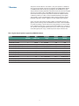
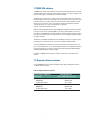
Agilent
Acqiris Broadband High-Speed Digitizers
Using 89600 Vector Signal Analyzer Software
Application Note
Vector signal analysis using
Agilent Acqiris broadband digitizers.
Table of Contents
1
Overview
1.1 89600 VSA software
1.2 Required software revisions
2 Install 89600 VSA Software
3 Hardware Configuration
3.1 I/O between computer and digitizer
3.2 Anti-alias filters and alias exposure-free mode
4 Operation
4.1 Basic operation
4.2 Sampling modes: full rate and user rate
4.3 Differences from 89600 VSA operation
5 Time and Frequency Span Operating Region
5.1 The relationship of main time length, span, and sample rate
5.2 Operating region curves for Agilent Acqiris digitizers
5.3 Recording limits for Agilent Acqiris digitizers
6 Out-of-Band Alias Exposure Zones
6.1 Setting up the alias exposure zone checker
6.2 Using the alias exposure zone checker
Appendix A
Appendix B
Appendix C
For More Information
Related Literature List
2
3
4
4
5
6
6
7
8
8
8
12
12
12
13
18
19
19
19
23
25
26
28
28
1 Overview
This product note describes the characteristics, setup, and operation of a broadband
vector signal analyzer (VSA) comprised of an Agilent Acqiris U1066A (DC440, DC438)
or U1065A (DC282, DC252, DC222) high-speed digitizer and the 89600 vector signal
analyzer software. By taking advantage of the layered architecture and extensive digital
signal processing (DSP) routines of the 89600 VSA software, the digitizer becomes
a new “front end” data acquisition subsystem for the VSA. This hardware-software
combination provides up to 2 GHz of analysis bandwidth depending on the digitizer
used. See Table 1 for the supported digitizer models and the corresponding analysis
bandwidths. Appendix A contains suggestions for ultra-wideband downconverters.
The 10- and 12-bit, high sample rate analog-to-digital converter (ADC) in the Acqiris
digitizers produces the large analysis bandwidths shown in Table 1. These bandwidths
are capable of providing a spurious-free dynamic range greater than or equal to 40 dB
for the U1065A and greater than or equal to 75 dB for the U1066A. This is sufficient for
1.5 to 2% error vector magnitude measurements in most cases. For spectrum measurements with higher dynamic range, a traditional spectrum analyzer should be used.
Table 1. Agilent Acqiris digitizers supported by 89600 VSA software
Model
No of
channels
Max
sample rate
Frequency
range
U1066A-001 (DC440)
1
400 M
dc – 100 MHz
U1066A-001 (DC440)
2
400 M
dc – 100 MHz
4M
8M
U1066A-001 (DC440) HF input
1
420 M
1 MHz – 300 MHz1
4M
8M
U1066A-001 (DC440) HF input
2
420 M
1 MHz – 300 MHz1
4M
8M
U1066A-002 (DC438)
1
200 M
dc – 78.125 MHz
4M
8M
U1066A-002 (DC438)
2
200 M
dc – 78.125 MHz
4M
8M
U1065A-001 (DC222)
1
8G
dc – 2 GHz
1M
128 M, 1 G
U1065A-002 (DC252)
1
8G
dc – 2 GHz
1M
128 M, 1 G
U1065A-002 (DC252)
2
4G
dc – 1.5625 GHz
512 k
64 M, 512 M
U1065A-004 (DC282)
1
8G
dc – 2 GHz
1M
128 M, 1 G
U1065A-004 (DC282)
2
4G
dc – 1.5625 GHz
512 k
64 M, 512 M
1. Max span = 164 MHz
3
Default
memory
Optional
memory
4M
8M
1.1 89600 VSA software
The 89600 vector signal analyzer software is the heart of the broadband VSA. This software
provides flexible tools for analyzing and demodulating even the most advanced digital modulations, including those not defined by an established standard.
The VSA makes measurements on signals in the time and frequency domains using either
the BB (baseband) or IF Zoom mode. In BB mode, the analysis frequency range is from 0 Hz
to the stop frequency. In IF Zoom mode, the analysis frequency range is defined by center
frequency and span. There is also an I+jQ mode for analyzing two baseband quadrature
channels. Results for any mode can be displayed as magnitude
or phase, in I/Q and several other formats.
With the optional digital demodulator, Option 89600-AYA, modulation quality measurements
in the form of error vector magnitude (EVM) can be made on digital wireless communications signals with bandwidths of hundreds of MHz. In addition, powerful diagnosis capabilities allow you to determine the exact impairments that cause a digitally modulated signal to
fail quality standards.
The features of the digital demodulator include variable-block-size signal acquisition, pulse
burst edge search, synch word search and a user-controllable adaptive equalizer.
User-selectable filter types include cosine (raised and square-root raised), Gaussian, lowpass, and user-defined. You can vary the filter alpha/BT shape factor. Supported modulation
formats for both burst and continuous carriers include FSK, BPSK, QPSK, OQPSK, DQPSK,
π/4DQPSK, 8PSK, QAM (16 to 1024), and MSK.
In addition, the 89600 software provides a signal record feature for later playback and
analysis.
1.2 Required software revisions
Using the 89600 Series VSA software with Agilent Acqiris high-speed digitizers requires
compatible software versions:
Table 2. Required software versions
Agilent Acqiris Software for
Windows®
AcqirisSoftware 3.2
(Driver AqDrv4.dll 4.13) or later
For baseband operation:
89600 VSA
Acqiris VSA Server
v8.00 or later
1.0 or later
For HF operation:
89600 VSA
Acqiris VSA Server
v9.00 or later
2.0 or later
4
2 Install 89600 VSA
Software
The 89600 VSA software must be installed on a computer.
Installation for standard operation
Insert the Agilent Technologies 89600 Series Software CD-ROM in your standard PC
and follow the instructions in the installation wizard. When the Installation Manager
window opens, click Install 89600 Series Software. In the Hardware Support window,
select Acqiris VSA Server. This will avoid installing unnecessary components on your
computer. After the software and hardware support is installed, exit the Installation
Manager window.
Installation for embedded operation
Operation of the 89600 Series software on an embedded Compact PCI computer is
similar to operation on a standard PC. The instructions for standard operation can be
followed here as well using a LAN or USB accessible CD drive.
Note: Before you can run the VSA with an Agilent Acqiris digitizer, make sure
the Agilent Acqiris digitizer hardware and driver software are installed and
configured as directed in the 89600 Series Installation and VXI Service Guide
found on your Agilent Technologies 89600 Series Software CD or go to
www.agilent.com/find/89600 then click on Technical Support > Manuals.
5
3 Hardware
Configuration
Connect the digitizer to the computer as shown in Figure 1a or 1b. There are two options
for the connection, by remote computer or by embedded computer.
3.1 I/O between computer and digitizer
Operation of the 89600 Series software on an embedded Compact PCI computer
is similar to operation on a standard PC. The instructions for standard operation
can be followed here as well using a LAN or USB accessible CD drive.
Agilent Acqiris data acquisition system
Agilent Acqir is digitizer
1
2
3
4
Optional anti-alias LPFs
Inter face
Input Ch 1
(Digitizer Ch 1)
Input Ch 2
(Digitizer Ch 2)
Figure 1a. Digitizers connected through CompactPCI to PCI interface
The digitizers can be connected through various interface types from a
CompactPCI crate to either a desktop PC or a portable PC.
Agilent Acqiris data acquisition system
Agilent Acqir is digitizer
1
2
3
4
Optional anti-alias LPFs
Embedded computer
Input Ch 1
(Digitizer Ch 1)
Input Ch 2
(Digitizer Ch 2)
Figure 1b. Digitizers connected through embedded single board PC
Alternatively, the digitizers can be controlled by an embedded computer as
shown in Figure 1b.
6
3.2 Anti-alias filters and alias exposure-free mode
The broadband VSA can be configured to be essentially alias-free by using the full
rate sampling mode and installing an external lowpass filter on the digitizer input.
Use BNC-f to SMA-m and SMA-f to BNC-m adapters to connect the filter’s SMA
connectors to the digitizer in case the digitizer has BNC connectors.
Table 3. External lowpass filters
Digitizer model
Cutoff frequency
Filter part number
U1066A-002 (DC438)
90 MHz
Mini-circuits BLP/SLP-90
MHz2
Mini-circuits1 BLP/SLP-100
U1066A-001 (DC440)
100
U1065A (DC252 (2 ch),
DC282 (2 ch))
1650 MHz
Mini-circuits1 SLP-1650
U1065A (DC222, DC252
(1 ch), DC282 (1ch))
2000 MHz
Mini-circuits1 SLP-2000
1. Mini-Circuits, Inc., 1-800-854-7949, www.minicircuits.com.
2. For the HF input a 300 MHz lowpass filter will avoid aliasing from signals above 300 MHz, but in-band
and out-of-band aliasing is still possible since full rate mode is not supported with the HF input.
7
4 Operation
4.1 Basic operation
Operation of the broadband VSA is substantially the same as that of the 89600
VSA. See the following sections for some differences or special configurations.
There is an online Tutorial and Getting Started Guide under the Help/Roadmap
toolbar in the 89600 software.
4.2 Sampling modes: full rate and user rate
Full rate mode
When the Sample Mode is set to full rate using the Utilities/Hardware/ADC1
/Agilent Acqiris One Channel Digitizer/Configure/Sample Mode/Edit menu
path for the U1065A-001 or Utilities/Hardware/ADC1 /Agilent Acqiris Two
Channel Digitizer/Configure/Sample Mode/Edit menu path for all the other
models, the digitizer sample rate is fixed at the maximum for each digitizer
model according to Table 4.
Table 4. Sample rates of Acqiris digitizers in full rate mode
Digitizer model
No. of channels
Full sample rate
U1066A-001 (DC440)
1
400 M
U1066A-001 (DC440)
2
400 M
U1066A-002 (DC438)
1
200 M
U1066A-002 (DC438)
2
200 M
U1065A-001 (DC222)
1
8G
U1065A-002 (DC252)
1
8G
U1065A-002 (DC252)
2
4G
U1065A-004 (DC282)
1
8G
U1065A-004 (DC282)
2
4G
With the addition of the anti-alias lowpass filter described above, this mode is
free of alias exposure zones. This means that no signal anywhere in the range
of the VSA’s center frequency will alias upon the desired signal and corrupt the
measurement.
There is a trade-off when using this mode. Although the digitizers have deep
memories allowing long record lengths, if a longer Main Time (or Result Length
for digital demodulation) is needed for more resolution in the frequency domain
a different sample mode may be required. Go to the Configure menu, click on
Sample Mode/Edit and select User Rate from the drop-down menu. The Main
Time limit for any sample rate is shown in the operating region curves that
appear in Appendix C.
NOTE: Any limitation to Main Time (or Result Length) will be indicated by the
inability of the software to increase the Main Time or decrease RBW when
Number of Frequency Points is increased.
8
User rate mode
The user rate setting allows you to directly control the digitizer’s sample rate. In
this mode you select the digitizer sample rate to be used. The actual sample rate
selected will be the highest rate that is less than or equal to the “user sample
rate” setting. By controlling the digitizer’s sample rate you can directly influence
the update rate of the VSA. This is because sample rate directly affects the number of points the digitizer must transfer to the PC. Certain measurements can be
made significantly faster by limiting the digitizer sample rate due to reduced data
transfer requirements.
There are two types of signal aliasing to be concerned with when using the
89600 VSA application with an Agilent Acqiris digitizer. The first is aliasing of
unwanted out-of-band signals into the measurement span. This will not be a
problem with the majority of clean, single-signal devices. However, devices with
multiple or spurious signals could have this type of aliasing. Section 6 describes
how to perform a check to determine if there are any unwanted signals present
that can alias down into the measurement span. A second type of aliasing happens when the sample rate causes the in-band signal to fold over on itself. This
in-band (or self-) aliasing is avoided in full rate mode by automatically selecting
the highest sample rate. However, in user rate mode in-band aliasing may be a
problem. To avoid in-band aliasing you must select a suitable sample rate based
on your measurement center frequency and span.
To avoid in-band aliasing the digitizer sample rate (FS) must be selected so that
the analysis span falls within confined regions. Staying within these regions
prevents the analysis span from being positioned too close to FS/2. When FS
is selected so that the span is confined to be within a single gray box (see
diagrams below), in-band aliasing is avoided. See the following table for the
equations that describe these in-band alias-free regions.
The primary use of user rate mode is to increase maximum waveform length that
can be acquired or to increase the update rate. In all cases, user rate measurements must be been carefully engineered to avoid unwanted alias signals.
Baseband:
DC
Fs/2.56
Fs/2
Zoom:
n * Fs
(n + 1/2) * Fs
(n + 1)Fs
Figure 2. Avoiding in-band aliasing by selecting FS within a confined span
NOTE: User Rate is the only available mode in HF operation. The VSA does not
attempt to avoid alias exposure regions when in User Rate mode.
9
This table summarizes the difference in approach to alias protection between
the various sample modes:
Table 5. Varying approaches for alias protection
Full rate
Both in-band and out-of-band aliasing are prevented through use
of the maximum sample rate and an appropriate lowpass filter.
User rate You are responsible to avoid in-band aliasing through appropriate
selection of sample rate based on center frequency and span. To
ensure no in-band aliasing is present the digitizer sample rate (FS)
must be selected to meet this criteria:
Baseband: FSTOP ≤ FS/2.56
Zoom: (n*FS)/2 ≤ FCENTER - (1.28 * FSPAN)/2
AND
((n+1)*FS)/2 ≥ FCENTER + (1.28 * FSPAN)/2
where n = 1,2,3,4…
Out-of-band aliasing is minimized through use of appropriate
low-pass filter. Use of Alias Checker macro (Section 6) is required
to detect other unwanted out-of-band signal aliasing.
(Note: aliasing of unwanted signals can be eliminated through use
of appropriate bandpass filter.)
Another concern in user rate mode is that you may see unwanted amplitude
variability in two channel measurements. This can occur if any part of the measurement frequency span falls within the regions defined by:
(2*n+1) x FS/2 ± 0.1 x FS
where n = 1, 2, 3, 4 …
where FS is the actual digitizer sample rate. Make sure you choose a sample rate
where such overlap does not occur.
4.3 Differences from 89600 VSA operation
•
•
•
No Magnitude Trigger (however, Channel Trigger is available).
Possible limitation of movement on the operating region curve to avoid alias
corruption of the measured signal. This depends on the settings of Center
Frequency, Span, Sample Mode, and Number of Frequency Points. There is
also potential interference due to the alias products of out-of-band signals.
(See Section 6.)
No built-in wideband calibrator. The frequency response corrections are
determined from factory data.
10
5 Time and
Frequency Span
Operating Region
The operating region curves for the broadband VSAs are different from those of
standard VSAs because the Main Time Length may be limited for some sample
rate, center frequency, and span combinations. The differences are due to three
hardware characteristics of the ultra-wideband ADCs in the Agilent Acqiris
digitizers:
•
•
•
A much higher sampling rate
The lack of a hardware decimator, which means the decimation must be
performed by the software from same-length records taken at much higher
sampling rates
Limited memory capacity
5.1 The relationship of main time length, span, and
sample rate
The record length or Main Time Length of a measurement is shown in the lower
right corner of a spectrum or time display window. This is the length of time the
digitizer sampled the input waveform for the measurement. These samples are
transferred to the DSP and measurement algorithms running on the software.
Maximum Main Time Length is normally adjusted by setting Number of Frequency
Points in the MeasSetup/ResBW menu ResBW Coupling is set to Auto, and
ResBW mode is set to Arbitrary or 1-3-10. The Time tab can then be used to set
Main Time Length up to this maximum limit. This setup keeps Main Time Length
maximized and within the DSP requirements.
Although Main Time Length can be adjusted directly by the MeasSetup/Time
menu, it cannot be greater than the limit imposed by the Number of Frequency
Points line on the operating region chart. See the online Help tool for a complete
discussion.
Note: The maximum Main Time Length can be found as follows:
The relationship between the parameters is shown below:
Max Main Time Length
= Number of frequency points
Span
where Span = Sample rate
1.28
Max Main Time Length = 1.28 x Number frequency points
Sample rate
where sample rate = current sample rate computed by the software for aliasfree measurements
Maximum Main Time Length may be further limited by digitizer memory depth.
11
5.2 Operating region curves for Agilent Acqiris digitizers
Several interrelated characteristics of both the Acqiris digitizers and the 89600 VSA
software combine to form a region within which the VSA is constrained to operate.
The 89600 VSA software characteristics that affect this operating region include
maximum number of time points, the minimum number of time points (not user
settable), a maximum acquisition record size (not user settable) and a maximum
decimation factor (not user settable). The Digitizer characteristics that affect the
operating region are sample rate and memory depth. This section describes the
effects each of these parameters has on the VSA operating region.
The operating region is described in terms of span and time record length. For a
given window type it could just as easily be described in terms of span and RBW.
Figure 3 shows the effects of the number of time points the 89600 VSA software is
allowed to collect. Because sample spacing is inversely proportional to span, the
record length decreases as span increases. Although a family of lines is shown,
only two define the operating region at any one time. The lowest line gives the
smallest time record length allowed for any given span. The position of this line
is determined by minimum number of time points (16) the VSA requires in a time
record. The line that defines the upper time record length boundary is positioned
by the maximum number of time points the VSA allows in a time record . The maximum number of time points is determined by the Frequency Points setting (MeasSetup/ResBWFrequency Points). The 89600 VSA is constrained to operate in the
region between these two lines. Note that the operating lines of Figure 3 are the
same for all digitizer models.
Operating region: number of frequency points limits
1.E+01
1.E+00
1.E-02
1.E-03
409601
204801
102401
51201
25601
12801
6401
3201
1601
801
401
201
1.E-04
1.E-05
1.E-06
1.E-07
Minimum
1.E-08
1.E+02
Number of frequency points
Time record length (sec)
1.E-01
1.E+03
1.E+04
1.E+05
1.E+06
1.E+07
1.E+08
1.E+09
1.E+10
1.E+11
Span (Hz)
Figure 3. The user-settable parameter, frequency points, begins to determine the
boundaries of the time record length and frequency span operating region
12
In addition to the time record length limits, there are limits to the allowable
range of spans. These are represented as vertical lines on the operating region
graphs (Figure 4). The upper span limit is set by the digitizer’s sample rate. For
the highest sample rate supported by the digitizer this boundary may be further
limited by the analog performance of the digitizer’s front-end. To zoom in on a
signal of interest by reducing the span, traditional VSA instrumentation reduces
the effective sample rate through the use of decimating filters while keeping
the ADC at full rate. This technique allows for maximum alias protection. Unlike
traditional VSA instruments, the Acqiris digitizers have no decimating filters.
To compensate for this shortcoming, decimating filters have been built into the
89600 VSA software. The maximum amount of decimation allowed by the 89600
VSA software sets the minimum span for any given digitizer sample rate.
The operating region depicted in Figure 4 is determined by constraints imposed
by both time record length and span. The Acqiris digitizers support many sample
rates. For each sample rate, the operating region shifts slightly on the operating
region graph. As the sample rate decreases, the operating region shifts slightly
up and to the left. So, for any given digitizer, there will be a family of overlapping
operating regions, one for each supported sample rate.
In general, these regions would be the same for every digitizer that supports a
given sample rate. The only difference is when the maximum span at the maximum sample rate is limited by analog performance of the digitizer’s front-end
rather than just by the sample rate.
In addition to the time record length limits, there are limits to the allowable
range of spans. These are represented as vertical lines on the operating region
graphs (Figure 4). The upper span limit is set by the digitizer’s sample rate. For
the highest sample rate supported by the digitizer this boundary may be further
limited by the analog performance of the digitizer’s front-end. To zoom in on a
signal of interest by reducing the span, traditional VSA instrumentation reduces
the effective sample rate through the use of decimating filters while keeping
the ADC at full rate. This technique allows for maximum alias protection. Unlike
traditional VSA instruments, the Acqiris digitizers have no decimating filters.
To compensate for this shortcoming, decimating filters have been built into the
89600 VSA software. The maximum amount of decimation allowed by the 89600
VSA software sets the minimum span for any given digitizer sample rate.
The operating region depicted in Figure 4 is determined by constraints imposed
by both time record length and span. The Acqiris digitizers support many sample
rates. For each sample rate, the operating region shifts slightly on the operating
region graph. As the sample rate decreases, the operating region shifts slightly
up and to the left. So, for any given digitizer, there will be a family of overlapping
operating regions, one for each supported sample rate.
Taken altogether, these constraints form an operating region that the 89600 VSA
software must remain within (Figure 6). To complete our understanding there are
a couple of additional points regarding sampling mode and alias exposure that
must be presented.
The graphs presented in this section describe discrete operating regions that are
a function of sample rate. In full rate or user rate sample modes a single operating region curve fully describes the constraints imposed on the measurement.
13
Operating region: span constraints
1.E+01
1.E+00
1.E-02
1.E-03
1.E-04
Number of frequency points
Time record length (sec)
1.E-01
409601
204801
102401
51201
25601
12801
6401
3201
1601
801
401
201
Operating region
1.E-05
1.E-06
1.E-07
Minimum
1.E-08
1.E+02
1.E+03
1.E+04
1.E+05
1.E+06
1.E+07
1.E+08
1.E+09
1.E+10
1.E+11
Span (Hz)
Figure 4. The allowable range of spans, which may differ by model, further bound
the operating region of the digitizer
Operating region: with memory constraints
1.E+01
1.E+00
1.E-02
1.E-03
1.E-04
Operating region
1.E-05
1.E-06
1.E-07
Minimum
1.E-08
1.E+02
409601
204801
102401
51201
25601
12801
6401
3201
1601
801
401
201
Number of frequency points
Time record length (sec)
1.E-01
1.E+03
1.E+04
1.E+05
1.E+06
1.E+07
1.E+08
1.E+09
1.E+10
1.E+11
Span (Hz)
Figure 5. The digitizer’s available memory also constrains the operating region
14
In full rate sample mode with the use of appropriate lowpass filtering (Table
3) signal aliasing is completely avoided. In this case the “Operating Region” is
renamed “Alias Exposure Free Zone” to indicate this special condition.
NOTE: Does not apply to HF operation.
Although the operating regions for all digitizer models are similar, each model
or model family may have important differences in their operating region curves
due to differences in maximum sample rate, front-end analog performance, and
memory option. Appendix C provides the operating curves for all supported digitizers and most memory options.
Operating region: with span and memory constraints
1.E+01
1.E+00
1.E-02
1.E-03
1.E-04
Operating region
1.E-05
1.E-06
1.E-07
Minimum
1.E-08
1.E+02
409601
204801
102401
51201
25601
12801
6401
3201
1601
801
401
201
Number of frequency points
Time record length (sec)
1.E-01
1.E+03
1.E+04
1.E+05
1.E+06
1.E+07
1.E+08
1.E+09
1.E+10
1.E+11
Span (Hz)
Figure 6. The true operating region is fully described when constrained by
all the previous parameters: number of frequency points, span, and digitizer
memory. See Appendix C for operating region charts for the various supported
digitizers.
15
5.3 Recording limits for Acqiris digitizers
The 89600 VSA software allows the acquisition of long records to be captured. Analysis
is done as a post-processing operation. This feature is called Recording. Recordings can
be much longer than time records in live measurements.
Prior to taking a recording, live test measurements of Main Time length are usually made
at the desired span. Then, when the recording is made, the analyzer no longer uses Main
Time Length but, instead, uses Recording Length to determine length of the acquired
record.
When making an 89600 VSA recording the maximum recording length is determined by
the digitizer sample rate and memory depth. When in user rate the maximum recording lengths will increase as the sample rate decreases. The recording length increase
is directly proportional to the sample rate decrease or the memory depth increase. The
following table indicates the maximum recording length at full rate for each supported
digitizer.
Table 6. Maximum recording lengths at maximum span for each digitizer model with memory
Model
No. of Max span
Ch's
Recording length for possible memory configurations
512k
1M
4M
8M
64M
128M
512M
1G
U1066A-001 (DC440) Std
1
100 MHz
−
−
10 ms
20 ms
−
−
−
−
U1066A-001 (DC440) Std
2
100 MHz
−
−
10 ms
20 ms
−
−
−
−
U1066A-001 (DC440) HF
1
164 MHz
–
–
10 ms
20 ms
–
–
–
–
U1066A-001 (DC440) HF
2
164 MHZ
–
–
10 ms
20 ms
–
–
–
–
U1066A-002 (DC438)
1
78.125 MHz
−
−
20 ms
40 ms
−
−
−
−
U1066A-002 (DC438)
2
78.125 MHz
−
−
20 ms
40 ms
−
−
−
−
U1065A-001 (DC222)
1
2 GHz
−
130 μs
−
−
−
16 ms
−
130 ms
U1065A-002 (DC252)
1
2 GHz
130 ms
U1065A-002 (DC252)
2
1.5625 GHz
U1065A-004 (DC282)
1
2 GHz
U1065A-004 (DC282)
2
1.5625 GHz
−
130 μs
−
−
−
16 ms
−
130 μs
−
−
−
16 ms
−
130 ms
−
130 μs
−
−
−
16 ms
−
130 ms
130 μs
−
−
−
16 ms
−
130 ms
−
Note: The stated recording depths are at maximum sample rate. Lower user sample rates give proportionally longer times.
16
6 Out-of-Band Alias
Exposure Zones
As mentioned above, the user rate sampling modes increase the maximum Main
Time length at the expense of possible aliasing of out-of-band signals into the
frequency span of the measurement. The spectrum ranges subject to the alias
conversion are called alias exposure zones. To determine if any out-of-band
signals exist in the exposure zones, run the Alias Exposure Zone Checker macro.
6.1 Setting up the Alias Exposure Zone Checker
Follow this procedure for setting up the Alias Exposure Zone Checker:
1. Start the VSA application.
2. Click on Utilities\Macros\Recall. Navigate to the Examples\Macros
subdirectory in the directory where you installed the VSA application (for
example, C:\Program Files\Agilent\89600 VSA\Examples\Macros). Select
RecallSetupAfterAliasCheck and AliasChecker files, and click OK.
3. Right click on the top of the VSA application. You will see a popup showing
the various toolbars. Select the Macros toolbar. This will make the alias
checker icons appear on your VSA application toolbar.
6.2 Using the Alias Exposure Zone Checker
The Alias Exposure Zone Checker calculates the frequencies of the alias
exposure zones for any combination of center frequency, span, and digitizer
sample rate. It then measures the power in each zone and compares it to the
power of the desired signal in the span of the measurement setup at the time
the checker was started. An unwanted signal in an exposure zone is a source of
interference if it is larger than the desired signal’s amplitude minus 40 dB. This
–40 dBc threshold is approximately the same level as the quantization errors in
the digitizer’s 10-bit digitizer, and represents the limit of the digitizer’s dynamic
range. The –40 dBc level is sufficient for 1 to 2 percent EVM measurements.
Launch the checker macro by using the tool path Utilities/Macros/Alias
Checker or click its icon (shown below) on the bottom of the tool bar.
NOTE: The Alias Exposure Zone Checker cannot be used with the U1066A-001
(DC440) HF Input.
When the macro stops, a full-span spectrum trace (Figure 7) will appear in Trace
A (green). It shows the desired signal plus any unwanted signals. Superimposed
is an orange Trace C showing boxes for each exposure zone frequency range.
Any unwanted signal falling inside the zone box is a source of alias interference.
If the height of any box is higher than the orange reference line, the power in
that zone is greater than the –40 dBc threshold of interference. Click Yes in the
checker dialog box to return to the original measurement setup. Click No for
further examination of the out-of-band signals. You can return to the original
measurement setup by clicking the Recall Setup After Alias Check macro icon.
17
Trace C
Trace A
Figure 7. Alias Exposure Zone Checker results. The desired signal is at 150 MHz and an out-ofband signal is at –35 dBc and 642 MHz. The unwanted signal in the second alias zone is 5 dB above
the –40 dBc threshold line.
When no alias zones exist because the current sampling mode is alias free, no
orange zone boxes will appear. In addition, the message No Alias Zones Detected!
Restore Initial Settings? will appear (see Figure 8).
Figure 8. Alias checker results when no
zones are detected. No orange alias zone
boxes appear.
18
When the original center frequency/span is inadvertently tuned to an alias
response of a signal whose frequency is not the center frequency, the checker
will attempt to suggest the signal’s frequency. The checker results at the desired
center frequency location (box formed by white solid and dashed lines) will show
no signal, and a large signal will appear in one of the zones, as shown in Figure 9.
Further, all zone boxes will be well above the orange threshold line.
Figure 9. Alias checker results when the
center frequency is originally tuned to an
alias product. The checker shows no signal at the desired frequency (white solid/
dashed box) and large zone boxes at the
zones containing the desired signal.
19
Appendix A
Downconverting RF and Microwave Signals into the
Range of the Agilent Acqiris Digitizers
External components with wide bandwidths can be used to downconvert signals
into the range of the broadband VSAs.
The 89600 VSA software can account for the mixing equation of the external
downconverter. While the downconverter cannot be controlled by the software,
the downconverter’s input center frequency, IF bandwidth, external bandwidth,
and IF mirroring can be taken into account by using the Utilities/Calibration /
Frequency menu picks. See the Help text for further details on using the external
frequency tool.
IF out
200 to 500 MHz
RF in
LO in
Bandpass filter: Mini-Circuits BLP-600
IF amp: Mini-Circuits ZFL-500
Figure 10. Block diagram of suggested downconverter. See Table 4 for further details.
Table 7. External wideband downconverter details
RF range
Mixer
0 to 2 GHz
(see Table 1)
LO
IF amp
Remarks
None
None
Use digitizer Ch1 or Ch2
(VSA Ch2)
0.2 to 6 GHz
Marki1
M2-0006MA
16 to 19 dBm
FLO = FRF - FIF
Mini Circuits2
ZFL-500
FIF – 200 -500 MHz
Mxr: CL = 8 dB, TOI = 18 dBm,
Amp: gain = 20 dB, NF = 5.5 dB,
TOI = +18 dBm
5 to 40 GHz
Marki1
M9-0540IN
3 to 17 dBm
FLO = FRF - FIF
As above
Mxr: CL = 8 dB, TOI = 16 dBm
25.6 to 40 GHz
Agilent
11970A
15 dBm
FLO = (FRF - FIF)/8
As above
8th harmonic waveguide mixer,
Mxr: CL = 22 dB, TOI = 15 dBm
33 to 50 GHz
Agilent
11970Q
15 dBm
FLO = (FRF - FIF)/10
FIF = 0 – 1 GHz
As above
10th harmonic waveguide mixer,
Mxr: CL = 24 dB, TOI = 15 dBm
1.
2.
Marki Microwave, http://www.markimicrowave.com Telephone: 408-778-4200, FAX: 408-778-4300, 215 Vineyard Court, Morgan Hill, CA 95037
Mini-Circuits, Inc., 1-800-654-7949, 44-1252-83600, http://www.minicircuits.com.
20
Appendix B
PC Requirements to Run 89600 Software
The 89600 requires a PC connected via the PCI extender to the Acqiris digitizer or an embedded PC. The PC must meet or exceed the following minimum
requirements:
Characteristic
Microsoft® Windows® XP Professional
CPU
600 MHz Pentium® or AMD-K6 > 600 MHz Pentium or AMD-K6
(> 2 GHz recommended)
Empty slots (desktop)
1 PCI-bus slot (two recommended) or 1 PCIe slot
Empty slots (laptop)
1 CardBus Type II slot or 1 ExpressCard slot
RAM
512 MB (1 GB recommended)
Video RAM
4 MB (16 MB recommended)
Hard disk
512 MB available
Additional drives
CD-ROM or USB storage device to load the software; License transfer
requires a 3.5 inch floppy disk drive, network access, or USB memory stick
Operating region curves
Operating region.
Model: Acqiris U1065A (DC222, DC252, DC282)
Memory: 1 Mpts
1.E+01
1.E+00
1.E-02
1.E-03
1.E-04
1.E-05
5 Msa/s
10 Msa/s
20 Msa/s
25 Msa/s
50 Msa/s
100 Msa/s
200 Msa/s
250 Msa/s
/
500 Msa/s
M
1 Gsa/s
2 Gsa/s
4 Gsa/s
a
Alias exposure
free zone
*
8 Gsa/s
1.E-06
1.E-07
Minimum
Time Rec Len
* One-channel operation only.
** Maximum span depends on model number – See Table 1.
1.E-08
1.E +02
1.E +03
1.E +04
1.E+05
1.E+06
Span (Hz)
21
409601
204801
102401
51201
25601
12801
6401
3201
1601
801
401
201
1.E+07
1.E+08
c points
Number of frequency
1.E-01
Time record length (sec)
Appendix C
**
1.E+09
1.E+10
Operating region
Model: Acqiris U1065A (DC222, DC252, DC282)
Memory: 256 Mpts and 1024 Mpts
1.E+01
1.E+00
1.E-01
5 Msa/s
10 Msa/s
20 Msa/s
25 Msa/s
50 Msa/s
100 Msa/s
200 Msa/s
/
250 Msa/s
M
500 Msa/s
1 Gsa/s
2 Gsa/s
a
4 Gsa/s
8 Gsa/s
1.E-04
1.E-05
409601
204801
102401
51201
25601
12801
Alias exposure
free zone
*
1.E-06
6401
3201
1601
801
401
1.E-07
1.E-08
1.E +02
1.E +03
1.E +04
201
Minimum
Time Rec Len
* One-channel operation only.
** Maximum span depends on model number – See Table 1.
1.E+05
1.E+06
1.E+07
1.E+08
Number of frequency points
1.E-03
**
1.E+09
1.E+10
Span (Hz)
Operating region
Model: Acqiris U1066A-001 (DC440) and U1066A-002 (DC438)
Memory: 4 Mpts
1.E+01
1.E+00
1.E-01
5 Msa/s
10 Msa/s
20 Msa/s
25 Msa/s
50 Msa/s
100 Msa/s
200 Msa/s
400 Msa/s
1.E-04
409601
204801
102401
51201
25601
12801
6401
Alias exposure
free zone
***
*
3201
1601
801
401
1.E-05
1.E-07
201
Minimum
Time Rec Len
1.E-06
**
**
* U1066A-001 only
** Maximum span depends on model number – See Table 1.
*** Alias exposure free zone does not apply to HF Input operation
1.E-08
1.E +02
1.E +03
1.E +04
Number of frequency points
1.E-03
1.E+05
1.E+06
1.E+07
1.E+08
1.E+09
Span (Hz)
Operating region
Model: Acqiris U1066A-001 (DC440) and U1066A-002 (DC438)
Memory: 8 Mpts
1.E+01
1.E+00
1.E-01
1.E-02
1.E-03
1.E-04
5 Msa/s
10 Msa/s
20 Msa/s
25 Msa/s
50 Msa/s
100 Msa/s
200 Msa/s
400 Msa/s
409601
Alias exposure
free zone
***
*
204801
102401
51201
25601
12801
6401
3201
1601
801
401
1.E-05
Minimum
Time Rec Len
1.E-06
1.E-07
1.E-08
1.E +02
201
***
* U1066A-001 only
** Maximum span depends on model number – See Table 1.
*** Alias exposure free zone does not apply to HF Input operation
1.E +03
1.E +04
1.E+05
1.E+06
Span (Hz)
22
n
points
q
m of frequency
Number
Time record length (sec)
1.E-02
Time record length (sec)
Time record length (sec)
1.E-02
1.E+07
1.E+08
1.E+09
For More
Information
For more product literature visit
www.agilent.com/find/89600
Related literature list
89600 Series Vector Signal Analyzers Installation and VXI Service Guide
Go to www.agilent.com/find/89600 then click on Technical Support > Manuals.
Understanding Time and Frequency Domain Interactions in the Agilent Technologies
89400 Series Vector Signal Analyzers, literature number 5962-9217EN
89600 Vector Signal Analyzer CD, literature number 5980-1989E
89600 Series Vector Signal Analysis Software 89600/89600N/ 89601N12,
Technical Overview, literature number 5989-1679EN
89600 Series Vector Signal Analysis Software 89600/89600N/ 89601N12,
Data Sheet, literature number 5989-1786EN
Agilent 6000 Series Digitizers Performance Guide Using 89600 Vector Signal
Analyzer Software, literature number 5989-4523EN
Hardware Measurement Platforms for the Agilent 89600 Series Vector Signal
Analysis Software, Data Sheet, literature number 5989-1753EN
89600 Series Vector Signal Analyzers, VXI Configuration Guide,
literature number 5968-9350E
89650S Wideband Vector Signal Analyzer System with High Performance Spectrum
Analysis, Technical Overview, literature number 5989-0871EN
89650S Wideband Vector Signal Analyzer System with High Performance Spectrum
Analysis, Configuration Guide, literature number 5989-1435EN
89607A WLAN Test Suite Software, Technical Overview,
literature number 5988-9574EN
89604A Distortion Test Suite Software, Technical Overview,
literature number 5988-7812EN
Microsoft, Windows, and XP Professional are U.S. registered trademarks of Microsoft Corporation.
Pentium is a U.S. registered trademark of Intel Corporation.
Product specifications and descriptions in this document subject to change without notice.
23
Agilent Email Updates
www.agilent.com/find/emailupdates
Get the latest information on the
products and applications you select.
Agilent Direct
www.agilent.com/find/agilentdirect
Quickly choose and use your test
equipment solutions with confidence.
Agilent
Open
www.agilent.com/find/open
Agilent Open simplifies the process
of connecting and programming
test systems to help engineers
design, validate and manufacture
electronic products. Agilent offers
open connectivity for a broad range
of system-ready instruments, open
industry software, PC-standard I/O
and global support, which are
combined to more easily integrate
test system development.
www.lxistandard.org
LXI is the LAN-based successor to
GPIB, providing faster, more efficient
connectivity. Agilent is a founding
member of the LXI consortium.
Remove all doubt
Our repair and calibration services
will get your equipment back to you,
performing like new, when promised. You will get full value out of
your Agilent equipment throughout its lifetime. Your equipment
will be serviced by Agilent-trained
technicians using the latest factory
calibration procedures, automated
repair diagnostics and genuine parts.
You will always have the utmost
confidence in your measurements.
Agilent offers a wide range of additional expert test and measurement services for your equipment,
including initial start-up assistance,
onsite education and training, as
well as design, system integration,
and project management.
For more information on repair and
calibration services, go to:
www.agilent.com/find/removealldoubt
www.agilent.com
www.agilent.com/find/89600
For more information on Agilent Technologies’
products, applications or services, please
contact your local Agilent office. The
complete list is available at:
www.agilent.com/find/contactus
Americas
Canada
Latin America
United States
(877) 894-4414
305 269 7500
(800) 829-4444
Asia Pacific
Australia
China
Hong Kong
India
Japan
Korea
Malaysia
Singapore
Taiwan
Thailand
1 800 629 485
800 810 0189
800 938 693
1 800 112 929
0120 (421) 345
080 769 0800
1 800 888 848
1 800 375 8100
0800 047 866
1 800 226 008
Europe & Middle East
Austria
01 36027 71571
Belgium
32 (0) 2 404 93 40
Denmark
45 70 13 15 15
Finland
358 (0) 10 855 2100
France
0825 010 700*
*0.125 €/minute
Germany
07031 464 6333**
**0.14 €/minute
Ireland
1890 924 204
Israel
972-3-9288-504/544
Italy
39 02 92 60 8484
Netherlands
31 (0) 20 547 2111
Spain
34 (91) 631 3300
Sweden
0200-88 22 55
Switzerland
0800 80 53 53
United Kingdom 44 (0) 118 9276201
Other European Countries:
www.agilent.com/find/contactus
Revised: July 17, 2008
Product specifications and descriptions
in this document subject to change
without notice.
© Agilent Technologies, Inc. 2008
Printed in USA, September 10, 2008
5989-7672EN