1
Agilent 34410A/11A/L4411A Programmer's Reference
Introduction to SCPI Language
Syntax Conventions
Command Separators
Using the MIN, MAX, and DEF Parameters
Querying Parameter Settings
SCPI Command Terminators
IEEE-488.2 Common Commands
SCPI Parameter Types
Numeric Parameters
Discrete Parameters
Boolean Parameters
ASCII String Parameters
Using Device Clear
Commands by Subsystem
ABORt
INITiate[:IMMediate]
OUTPut:TRIGger:SLOPe
R?
READ?
ROUTe:TERMinals?
UNIT:TEMPerature
CALCulate Subsystem
CALCulate:FUNCtion
CALCulate:STATe
CALCulate:LIMit:LOWer
CALCulate:LIMit:UPPer
CALCulate:DB:REFerence
CALCulate:DBM:REFerence
CALCulate:NULL:OFFSet
CALCulate:AVERage:AVERage?
CALCulate:AVERage:CLEar
CALCulate:AVERage:COUNt?
CALCulate:AVERage:MAXimum?
CALCulate:AVERage:MINimum?
CALCulate:AVERage:PTPeak?
CALCulate:AVERage:SDEViation?
CALibration Subsystem
CALibration:ADC?
CALibration[:ALL]?
CALibration:COUNt?
CALibration:LFRequency
CALibration:LFRequency:ACTual?
CALibration:SECure:CODE
CALibration:SECure:STATe
CALibration:STRing
CALibration:STORe
CALibration:VALue
CONFigure Subsystem
CONFigure:CAPacitance
CONFigure:CONTinuity
CONFigure:CURRent:AC
CONFigure:CURRent[:DC]
CONFigure:DIODe
CONFigure:FREQuency
CONFigure:FRESistance
CONFigure:PERiod
CONFigure:RESistance
CONFigure:TEMPerature
CONFigure[:VOLTage]:AC
CONFigure[:VOLTage][:DC]
CONFigure?
DATA Subsystem
DATA:COPY
DATA:DATA?
DATA:DELete
DATA:LAST?
DATA:POINts:EVENt:THReshold
DATA:POINts?
DATA:REMove?
DISPlay Subsystem
DISPlay[:WINDow[1|2][:STATe]]
DISPlay[:WINDow[1|2]]:TEXT:CLEar
DISPlay[:WINDow[1|2]]:TEXT[:DATA]
DISPlay:WINDow2:TEXT:FEED
FETCh Subsystem
FETCh?
FETCh:CURRent:AC:PTPeak?
FETCh:CURRent[:DC]:PEAK:MAXimum?
FETCh:CURRent[:DC]:PEAK:MINmum?
FETCh:CURRent[:DC]:PTPeak?
FETCh:VOLTage:AC:PTPeak?
FETCh:VOLTage[:DC]:PEAK:MAXimum?
FETCh:VOLTage[:DC]:PEAK:MINmum?
FETCh:VOLTage[:DC]:PTPeak?
FORMat Subsystem
FORMat:BORDer
FORMat[:DATA]
IEEE-488 Commands
*CLS
*ESE
*ESR?
*IDN?
*LRN?
*OPC
*OPC?
*PSC
*RCL
*RST
*SAV
*SRE
*STB?
*TRG
*TST?
*WAI
MEASure Subsystem
MEASure:CAPacitance?
MEASure:CONTinuity?
MEASure:CURRent:AC?
MEASure:CURRent[:DC]?
MEASure:DIODe?
MEASure:FREQuency?
MEASure:FRESistance?
MEASure:PERiod?
MEASure:RESistance?
MEASure:TEMPerature?
MEASure[:VOLTage]:AC?
MEASure[:VOLTage][:DC]?
MEMory Subsystem
MEMory:NSTATes?
MEMory:STATe:CATalog?
MEMory:STATe:DELete
MEMory:STATe:NAME
MEMory:STATe:RECall:AUTO
MEMory:STATe:RECall:SELect
MEMory:STATe:VALid?
SAMPle Subsystem
SAMPle:COUNt
SAMPle:COUNt:PRETrigger (34411A only)
SAMPle:SOURce
SAMPle:TIMer
SENSe Subsystem
[SENSe:]FUNCtion
[SENSe:]CAPacitance:NULL[:STATe]
[SENSe:]CAPacitance:NULL:VALue
[SENSe:]CAPacitance:RANGe:AUTO
[SENSe:]CAPacitance:RANGe[:UPPer]
[SENSe:]CURRent:AC:BANDwidth
[SENSe:]CURRent:AC:NULL[:STATe]
[SENSe:]CURRent:AC:NULL:VALue
[SENSe:]CURRent:AC:PEAK:STATe
[SENSe:]CURRent:AC:RANGe:AUTO
[SENSe:]CURRent:AC:RANGe[:UPPer]
[SENSe:]CURRent[:DC]:APERture
[SENSe:]CURRent[:DC]:APERture:ENABled
[SENSe:]CURRent[:DC]:NPLC
[SENSe:]CURRent[:DC]:NULL[:STATe]
[SENSe:]CURRent[:DC]:NULL:VALue
[SENSe:]CURRent[:DC]:PEAK:STATe
[SENSe:]CURRent[:DC]:RANGe:AUTO
[SENSe:]CURRent[:DC]:RANGe[:UPPer]
[SENSe:]CURRent[:DC]:RESolution
[SENSe:]CURRent[:DC]ZERO:AUTO
[SENSe:]FREQuency:APERture
[SENSe:]FREQuency:NULL[:STATe]
[SENSe:]FREQuency:NULL:VALue
[SENSe:]FREQuency:RANGe:LOWer
[SENSe:]FREQuency:VOLTage:RANGe:AUTO
[SENSe:]FREQuency:VOLTage:RANGe[:UPPer]
[SENSe:]PERiod:APERture
[SENSe:]PERiod:NULL[:STATe]
[SENSe:]PERiod:NULL:VALue
[SENSe:]PERiod:RANGe:LOWer
[SENSe:]PERiod:VOLTage:RANGe:AUTO
[SENSe:]PERiod:VOLTage:RANGe[:UPPer]
[SENSe:]FRESistance:APERture
[SENSe:]FRESistance:APERture:ENABled
[SENSe:]FRESistance:NPLC
[SENSe:]FRESistance:NULL[:STATe]
[SENSe:]FRESistance:NULL:VALue
[SENSe:]FRESistance:OCOMpensated
[SENSe:]FRESistance:RANGe:AUTO
[SENSe:]FRESistance:RANGe[:UPPer]
[SENSe:]FRESistance:RESolution
[SENSe:]RESistance:APERture
[SENSe:]RESistance:APERture:ENABled
[SENSe:]RESistance:NPLC
[SENSe:]RESistance:NULL[:STATe]
[SENSe:]RESistance:NULL:VALue
[SENSe:]RESistance:OCOMpensated
[SENSe:]RESistance:RANGe:AUTO
[SENSe:]RESistance:RANGe[:UPPer]
[SENSe:]RESistance:RESolution
[SENSe:]RESistance:ZERO:AUTO
[SENSe:]TEMPerature:APERture
[SENSe:]TEMPerature:APERture:ENABled
[SENSe:]TEMPerature:NPLC
[SENSe:]TEMPerature:NULL[:STATe]
[SENSe:]TEMPerature:NULL:VALue
[SENSe:]TEMPerature:TRANsducer:TYPE
[SENSe:]TEMPerature:ZERO:AUTO
[SENSe:]TEMPerature:TRANsducer:FRTD:OCOMpensated
[SENSe:]TEMPerature:TRANsducer:FRTD:RESistance[:REFerence]
[SENSe:]TEMPerature:TRANsducer:FRTD:TYPE
[SENSe:]TEMPerature:TRANsducer:RTD:OCOMpensated
[SENSe:]TEMPerature:TRANsducer:RTD:RESistance[:REFerence]
[SENSe:]TEMPerature:TRANsducer:RTD:TYPE
[SENSe:]TEMPerature:TRANsducer:THERmistor:TYPE
[SENSe:]TEMPerature:TRANsducer:FTHermistor:TYPE
[SENSe:]VOLTage:AC:BANDwidth
[SENSe:]VOLTage:AC:NULL[:STATe]
[SENSe:]VOLTage:AC:NULL:VALue
[SENSe:]VOLTage:AC:PEAK:STATe
[SENSe:]VOLTage:AC:RANGe:AUTO
[SENSe:]VOLTage:AC:RANGe[:UPPer]
[SENSe:]VOLTage[:DC]:APERture
[SENSe:]VOLTage[:DC]:APERture:ENABled
[SENSe:]VOLTage[:DC]:IMPedance:AUTO
[SENSe:]VOLTage[:DC]:NPLC
[SENSe:]VOLTage[:DC]:NULL[:STATe]
[SENSe:]VOLTage[:DC]:NULL:VALue
[SENSe:]VOLTage[:DC]:PEAK:STATe
[SENSe:]VOLTage[:DC]:RANGe:AUTO
[SENSe:]VOLTage[:DC]:RANGe[:UPPer]
[SENSe:]VOLTage[:DC]:RESolution
[SENSe:]VOLTage[:DC]:ZERO:AUTO
STATus Subsystem
STATus:OPERation:CONDition?
STATus:OPERation:ENABle
STATus:OPERation[:EVENt]?
STATus:PRESet
STATus:QUEStionable:CONDition?
STATus:QUEStionable:ENABle
STATus:QUEStionable[:EVENt]?
SYSTem Subsystem
SYSTem:COMMunicate:LAN:AUTOip[:STATe]
SYSTem:COMMunicate:LAN:BSTatus?
SYSTem:COMMunicate:LAN:CONTrol?
SYSTem:COMMunicate:LAN:DDNS
SYSTem:COMMunicate:LAN:DHCP
SYSTem:COMMunicate:LAN:DNS
SYSTem:COMMunicate:LAN:DOMain
SYSTem:COMMunicate:LAN:GATEway
SYSTem:COMMunicate:LAN:HISTory?
SYSTem:COMMunicate:LAN:HISTory:CLEar
SYSTem:COMMunicate:LAN:HOSTname
SYSTem:COMMunicate:LAN:IPADdress
SYSTem:COMMunicate:LAN:KEEPalive
SYSTem:COMMunicate:LAN:LIPaddress?
SYSTem:COMMunicate:LAN:MAC?
SYSTem:COMMunicate:LAN:MEDiasense
SYSTem:COMMunicate:LAN:NETBios
SYSTem:COMMunicate:LAN:SMASk
SYSTem:COMMunicate:LAN:TELNet:PROMpt
SYSTem:COMMunicate:LAN:TELNet:WMESsage
SYSTem:BEEPer:STATe
SYSTem:BEEPer[:IMMediate]
SYSTem:COMMunicate:ENABle
SYSTem:COMMunicate:GPIB[:SELF]:ADDRess
SYSTem:ERRor[:NEXT]?
SYSTem:HELP?
SYSTem:LANGuage
SYSTem:LFRequency?
SYSTem:LFRequency:ACTual?
SYSTem:LOCK:NAME?
SYSTem:LOCK:OWNer?
SYSTem:LOCK:RELease
SYSTem:LOCK:REQuest?
SYSTem:PRESet
SYSTem:SECurity:IMMediate
SYSTem:VERSion?
TRIGger Subsystem
TRIGger:COUNt
TRIGger:DELay
TRIGger:DELay:AUTO
TRIGger:LEVel (34411A only)
TRIGger:SLOPe
TRIGger:SOURce
Commands A-Z
Command Quick Reference
Syntax Conventions
Measurement Commands
Temperature Configuration Commands
Voltage Configuration Commands
Resistance Configuration Commands
Current Configuration Commands
Capacitance Configuration Commands
Continuity and Diode Configuration Commands
Frequency and Period Configuration Commands
Measurement Configuration Commands
Triggering Commands
Measurement Statistics Commands
Reading Memory Commands
Calibration Commands
State Storage Commands
IEEE-488 Commands
System-Related Commands
Remote Interface Configuration Commands
LAN Configuration Commands
Status System Commands
SCPI Error Messages
Execution Errors
Instrument Errors
Self-Test Errors
Calibration Errors
Firmware Update Errors
Power-On and Reset State
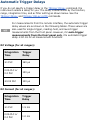
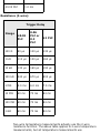
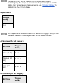
Automatic Trigger Delays
Agilent 34401A Compatibility Mode
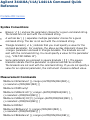
Agilent 34410A/11A/L4411A 6½ Digit
Multimeter
Programmer's Reference
This Help file contains reference information to help you program the
Agilent 34410A/11A/L4411A over a remote interface using the SCPI
programming language.
Introduction to the SCPI Language
Commands by Subsystem
Commands A-Z
Command Quick Reference
SCPI Error Messages
Power-On and Reset State
Automatic Trigger Delays
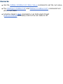
Related Information
IO Libraries and Instrument Drivers
Agilent 34410A/11A/L4411A Documentation
Agilent 34410A/11A/L4411A Web Interface
Example Programs
Contact Agilent Technologies
Trademarks
Copyright © 2005-2012 Agilent
Technologies, Inc.
Version 1.4 (3/1/2012)
Introduction to the SCPI Language
SCPI (Standard Commands for Programmable Instruments) is an ASCII-based
instrument command language designed for test and measurement
instruments. SCPI commands are based on a hierarchical structure, also known
as a tree system. In this system, associated commands are grouped together
under a common node or root, thus forming subsystems. A portion of the
SENSe subsystem is shown below to illustrate the tree system.
SENSe:
VOLTage:
DC:RANGe {<range>|MIN|MAX|DEF}
DC:RANGe? [MIN|MAX]
RESistance:
OCOMpensated {OFF|0|ON|1}
OCOMpensated?
SENSe is the root keyword of the command, VOLTage and RESistance are
second-level keywords, and DC and OCOMpensated are third-level keywords.
A colon ( : ) separates a command keyword from a lower-level keyword.
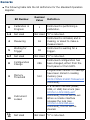
Syntax Conventions
The format used to show commands is illustrated below:
VOLTage:DC:RANGe {<range>|MIN|MAX|DEF}
The command syntax shows most commands (and some parameters) as
a mixture of upper- and lower-case letters. The upper-case letters indicate the
abbreviated spelling for the command. For shorter program lines, you can send
the abbreviated form. For better program readability, you can send the long
form.
For example, in the above syntax statement, VOLT and VOLTAGE are both
acceptable forms. You can use upper- or lower-case letters. Therefore,
VOLTAGE, volt, and Volt are all acceptable. Other forms, such as VOL and
VOLTAG, are not valid and will generate an error.
Braces ( { } ) enclose the parameter choices for a given command string.
The braces are not sent with the command string.
A vertical bar ( | ) separates multiple parameter choices for a given
command string. For example, {<range>|MIN|MAX|DEF} in the above
command indicates that you can specify a numeric range parameter, or
"MIN", "MAX", or "DEF". The bar is not sent with the command string.
Triangle brackets ( < > ) indicate that you must specify a value for the
enclosed parameter. For example, the above syntax statement shows the
<range> parameter enclosed in triangle brackets. The brackets are not sent
with the command string. You must specify a value for the parameter (for
example "VOLT:DC:RANG 10") unless you select one of the other options
shown in the syntax (for example "VOLT:DC:RANG MIN").
Some parameters are enclosed in square brackets ( [ ] ). This indicates that
the parameter is optional and can be omitted. The brackets are not sent with
the command string. If you do not specify a value for an optional parameter,
the instrument chooses a default value.
Command Separators
A colon ( : ) is used to separate a command keyword from a lower-level
keyword. You must insert a blank space to separate a parameter from a
command keyword. If a command requires more than one parameter, you
must separate adjacent parameters using a comma as shown below:
CONF:VOLT:DC 10,0.003
A semicolon ( ; ) is used to separate commands within the same subsystem,
and can also minimize typing. For example, sending the following command
string:
TRIG:SOUR EXT; COUNT 10
... is the same as sending the following two commands:
TRIG:SOUR EXT
TRIG:COUNT 10
Use a colon and a semicolon to link commands from different subsystems. For
example, in the following command string, an error is generated if you do not
use both the colon and semicolon:
TRIG:COUN MIN;:SAMP:COUN MIN
Using the MIN, MAX, and DEF Parameters
For many commands, you can substitute "MIN" or "MAX" in place of a
parameter. In some cases you may also substitute "DEF". For example,
consider the following command:
VOLTage:DC:RANGe {<range>|MIN|MAX|DEF}
Instead of selecting a specific value for the <range> parameter, you can
substitute MIN to set the range to its minimum value, MAX to set the range to
its maximum value, or DEF to set the range to its default value.
Querying Parameter Settings
You can query the current value of most parameters by adding a
question mark ( ? ) to the command. For example, the following command sets
the trigger count to 10 readings:
TRIG:COUN 10
You can then query the count value by sending:
TRIG:COUN?
You can also query the minimum or maximum count allowed as follows:
TRIG:COUN? MIN
TRIG:COUN? MAX
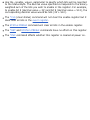
SCPI Command Terminators
A command string sent to the instrument must terminate with a <new line>
(<NL>) character. The IEEE-488 EOI (End-Or-Identify) message is interpreted
as a <NL> character and can be used to terminate a command string in place
of a <NL> character. A <carriage return> followed by a <NL> is also accepted.
Command string termination will always reset the current SCPI command path
to the root level.
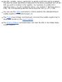
For every SCPI message that includes a query and is sent to the
instrument, the instrument terminates the returned response with
a <NL> or line-feed character (EOI). For example, if R? is sent, the
response is terminated with a <NL> after the block of data that is
returned. If a SCPI message includes multiple queries separated by
semicolons (for example "ROUTe:TERMinals?;R?"), the returned
response is again terminated by a <NL> after the response to the
last query. In either case, the program must read this <NL> in the
response before another command is sent to the instrument, or an
error will occur.
IEEE-488.2 Common Commands
The IEEE-488.2 standard defines a set of common commands that perform
functions such as reset, self-test, and status operations. Common commands
always begin with an asterisk ( * ), are three characters in length, and may
include one or more parameters. The command keyword is separated from the
first parameter by a blank space. Use a semicolon ( ; ) to separate multiple
commands as shown below:
*RST; *CLS; *ESE 32; *OPC?
SCPI Parameter Types
The SCPI language defines several data formats to be used in program
messages and response messages.
Numeric Parameters
Commands that require numeric parameters will accept all commonly used
decimal representations of numbers including optional signs, decimal points,
and scientific notation. Special values for numeric parameters such as MIN,
MAX, and DEF are also accepted. You can also send engineering unit suffixes
with numeric parameters (e.g., M, k, m, or u). If a command accepts only
certain specific values, the instrument will automatically round the input
numeric parameters to the accepted values. The following command requires a
numeric parameter for the range value:
VOLTage:DC:RANGe {<range>|MIN|MAX|DEF}
Because the SCPI parser is case-insensitive, there is some
confusion over the letter "M" (or "m"). For your convenience, the
instrument interprets "mV" (or "MV") as millivolts, but "MHZ" (or
"mhz") as megahertz. Likewise "MΩ" (or "mΩ") is interpreted as
megohms. You can use the prefix "MA" for mega. For example,
"MAV" is interpreted as megavolts.
Discrete Parameters
Discrete parameters are used to program settings that have a limited number
of values (like IMMediate, EXTernal, or BUS). They have a short form and a
long form just like command keywords. You can mix upper- and lower-case
letters. Query responses will always return the short form in all upper-case
letters. The following command requires a discrete parameters for the
temperature units:
UNIT:TEMPerature {C|F|K}
Boolean Parameters
Boolean parameters represent a single binary condition that is either true or
false. For a false condition, the instrument will accept "OFF" or "0". For a true
condition, the instrument will accept "ON" or "1". When you query a boolean
setting, the instrument will always return "0" or "1". The following command
requires a boolean parameter:
VOLTage:DC:IMPedance:AUTO {OFF|0|ON|1}
ASCII String Parameters
String parameters can contain virtually any set of ASCII characters. A string
must begin and end with matching quotes; either with a single quote or a
double quote. You can include the quote delimiter as part of the string by
typing it twice without any characters in between. The following command uses
a string parameter:
DISPlay:TEXT <quoted string>
For example, the following command displays the message "WAITING..." on
the instrument's front panel (the quotes are not displayed).
DISP:TEXT "WAITING..."
You can also display the same message using the following command with
single quotes.
DISP:TEXT 'WAITING...'
Using Device Clear
Device Clear is an IEEE-488 low-level bus message that you can use to return
the instrument to a responsive state. Different programming languages and
IEEE-488 interface cards provide access to this capability through their own
unique commands. The status registers, the error queue, and all configuration
states are left unchanged when a Device Clear message is received.
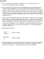
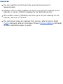
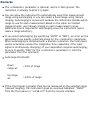
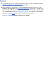
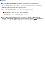
Device Clear performs the following actions:
If a measurement is in progress, it is aborted.
The instrument returns to the trigger "idle" state.
The instrument's input and output buffers are cleared.
The instrument is prepared to accept a new command string.
An overlapped command, if any, will be terminated with no "Operation
Complete" indication (applies to the INIT command).
The ABORt command is the recommended method to terminate a
measurement.
Commands by Subsystem
Other Commands
CALCulate Subsystem
CALibration Subsystem
CONFigure Subsystem
DATA Subsystem
DISPlay Subsystem
FETCh Subsystem
FORMat Subsystem
IEEE-488.2 Common Commands
MEASure Subsystem
MEMory Subsystem
SAMPle Subsystem
SENSe Subsystem
STATus Subsystem
SYSTem Subsystem
TRIGger Subsystem
ABORt
Syntax | Description | Parameters | Remarks | Return Format | Example
Syntax
ABORt
Description
This command aborts a measurement in progress.
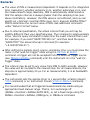
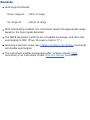
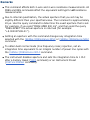
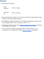
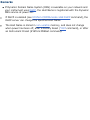
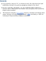
Remarks
This command may be useful to abort a measurement when the
instrument is waiting for a trigger, for a long measurement (for example,
100 plc), or for a long series of timed measurements.
The command will abort a measurement in progress and stop, returning
the instrument to the trigger idle state.
The *RST command will abort a measurement and set all measurement
parameters to their factory settings. The Instrument Preset
(SYSTem:PRESet command) does the same.
Example
The following command aborts the measurement in progress.
ABOR
See Also
*RST
SYSTem:PRESet
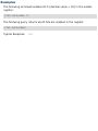
INITiate[:IMMediate]
Syntax | Description | Parameters | Remarks | Return Format | Example
Syntax
INITiate[:IMMediate]
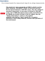
Description
This command changes the state of the triggering system from the "idle"
state to the "wait-for-trigger" state. Measurements will begin when the
specified trigger conditions are satisfied following the receipt of the INITiate
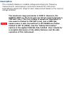
command. Note that the INITiate command also clears the previous set of
readings from memory.
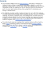
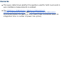
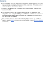
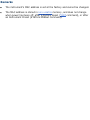
Remarks
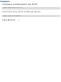
Storing readings in memory using the INITiate command is faster than
sending readings to the output buffer using the READ? command. The
INITiate command is also an "overlapped" command. This means that after
executing the INITiate command, you can send other commands that do
not affect the measurements.
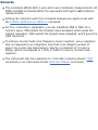
The 34410A provides volatile reading memory for up to 50,000 readings.
The 34411A/L4411A provides volatile reading memory for up to 1,000,000
readings. If memory overflows, the new readings will overwrite the first
(oldest) readings stored; the most recent readings are always preserved.
In addition, bit 14 (Mem Ovfl) is set in the Questionable Data Register's
condition register (see Status System Introduction).
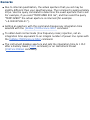
To retrieve the readings from memory, use the FETCh? command. Use
DATA:REMove? to remove data points. Or use the R? command to read and
remove all of the available data.
The ABORt command may be used to return to idle.
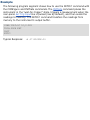
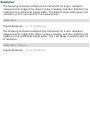
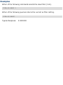
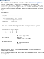
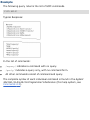
Example
The following program segment shows how to use the INITiate command
with the CONFigure and FETCh? commands. The INITiate command places
the instrument in the "wait-for-trigger" state, triggers a measurement when
the rear-panel Ext Trig Inputline is pulsed (low by default), and then sends
the readings to memory. The FETCh? command transfers the readings from
memory to the instrument's output buffer.
CONF:VOLT:DC 10,0.003
TRIG:SOUR EXT
INIT
FETC?
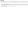
Typical Response:
+4.27150000E-03
See Also
FETCh?
READ?
ABORt
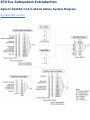
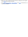
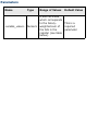
OUTPut:TRIGger:SLOPe
Syntax | Description | Parameters | Remarks | Return Format | Examples
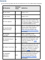
Syntax
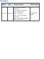
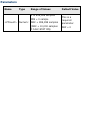
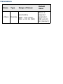
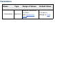
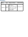
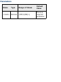
OUTPut:TRIGger:SLOPe <slope>
OUTPut:TRIGger:SLOPe?
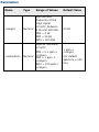
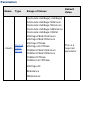
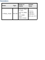
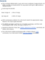
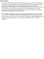
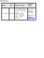
Description
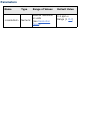
This command selects the slope of the voltmeter complete output signal on
the rear-panel VM Comp BNC connector. The default is NEG.
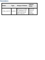
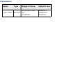
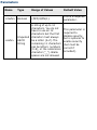
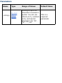
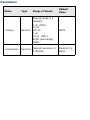
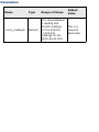
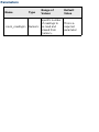
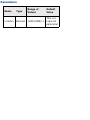
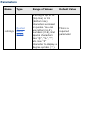
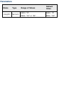
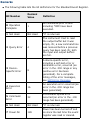
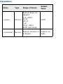
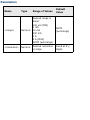
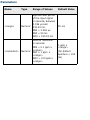
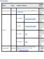
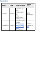
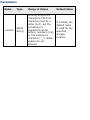
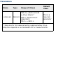
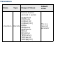
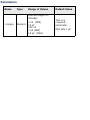
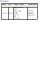
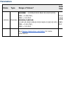
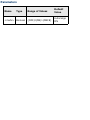
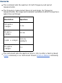
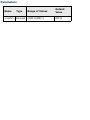
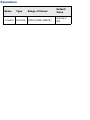
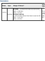
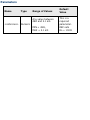
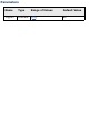
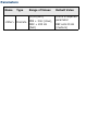
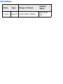
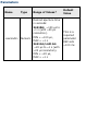
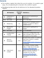
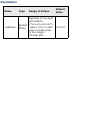
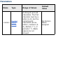
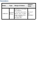
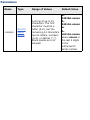
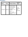
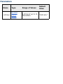
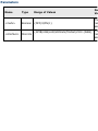
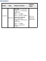
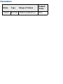
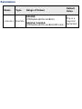
Parameters
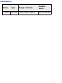
Name
Type
Range of Values
Default
Value
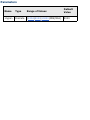
<slope>
Discrete
{POSitive|NEGative}
NEG
Remarks
See VM Comp Output for further information.
The instrument selects a negative slope after a Factory Reset (*RST
command) or an Instrument Preset (SYSTem:PRESet command).
Return Format
The query command returns either "POS" or "NEG".
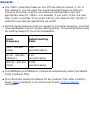
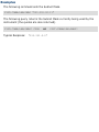
Examples
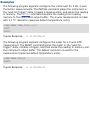
The following command sets the VM Comp slope to negative.
OUTP:TRIG:SLOP NEG
The following query returns currently selected slope.
OUTP:TRIG:SLOP?
Typical Response:
NEG
See Also
VM Comp Output
R?
Syntax | Description | Parameters | Remarks | Return Format | Example
Syntax
R? [<max_count>]
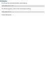
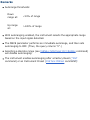
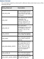
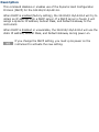
Description
This command reads and erases readings from volatile memory up to the
specified <max_count>. The readings are erased from memory starting with
the oldest (not the most recent) reading first. The purpose of this command
is to allow you to periodically remove readings from memory that would
normally cause reading memory to overflow.
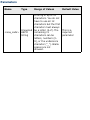
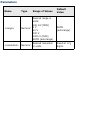
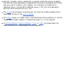
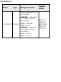
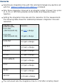
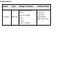
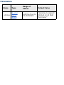
Parameters
Name
<max_count>
Type
Range of Values
Default
Value
Numeric
Maximum number
of readings to be
read and erased
from memory.
Read and
erase all
stored
readings
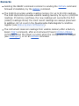
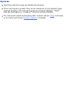
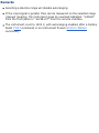
Remarks
This command differs from the DATA:REMove? command in that R? will
read and erase whatever readings are available in memory, up to the
specified <max_count>. On the other hand, DATA:REMove will error if the
requested number of readings are not in memory when the command is
sent. You can read memory at any time using the R? command, even
during a measurement.
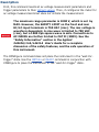
The 34410A provides volatile reading memory for up to 50,000 readings.
The 34411A/L4411A provides volatile reading memory for up to 1,000,000
readings. If memory overflows, the new readings will overwrite the first
(oldest) readings stored; the most recent readings are always preserved.
In addition, bit 14 (Mem Ovfl) is set in the Questionable Data Register's
condition register (see Status System Introduction).
The instrument clears all readings from volatile memory after a Factory
Reset (*RST command), after an Instrument Preset (SYSTem:PRESet
command), when mainframe power is cycled, when the configuration is
changed (see CONFigure), or on an INITiate command.
Return Format
The command returns a series of readings in Definite-Length Block format.
The syntax is a pound sign (#) followed by a non-zero digit representing the
number of digits in the decimal integer to follow. This digit is followed by a
decimal integer indicating the number of 8-bit data bytes to follow. This is
followed by a block of data containing the specified number of bytes. The
reading format is determined by the FORMat Subsystem commands.
Example
This command reads the two oldest readings and erases them from memory.
R? 2
Typical Response:
#231+2.87536000E-04,+3.18131400E-03
See Also
DATA:REMove?
FETCh?
FORMat:BORDer
FORMat[:DATA]
READ?
Syntax | Description | Parameters | Remarks | Return Format | Examples
Syntax
READ?
Description
This command changes the instrument's triggering system from the "idle"
state to the "wait-for-trigger" state. Measurements will begin when the
specified trigger conditions are satisfied following the receipt of the READ?
command. Readings are then sent immediately to volatile memory and the
instrument's output buffer.
Remarks
Sending the READ? command is similar to sending the INITiate command
followed immediately by the FETCh? command.
The 34410A provides volatile reading memory for up to 50,000 readings.
The 34411A/L4411A provides volatile reading memory for up to 1,000,000
readings. If memory overflows, the new readings will overwrite the first
(oldest) readings stored; the most recent readings are always preserved.
In addition, bit 14 is set in the Questionable Data Register's condition
register (see Status System Introduction).
The instrument clears all readings from volatile memory after a Factory
Reset (*RST command), after an Instrument Preset (SYSTem:PRESet
command), when the power is cycled, when the configuration is changed
(see CONFigure), or on an INITiate command.
Return Format
The command sends readings directly to reading memory and the
instrument's output buffer. The readings are returned in ASCII format.
Examples
The following program segment shows how to use the READ? command with
the CONFigure command. The READ? command places the instrument in the
"wait-for-trigger" state, triggers a measurement when the rear-panel Ext
Trig Inputline is pulsed (low by default), sends the readings to memory, and
then transfers the readings to the instrument output buffer.
CONF:VOLT:DC 10,0.003
TRIG:SOUR EXT
READ?
Typical Response:
+4.27150000E-03
The following program segment shows how to use the READ? command to
make a dc voltage measurement. The CONFigure command configures the
meter for a dc voltage measurement and sets the trigger source to
IMMediate. The READ? command places the meter in the "wait-for-trigger"
state, initiates a trigger, and then sends the reading to memory.
CONF:VOLT:DC
READ?
Typical Response:
+1.26360000E-02
See Also
FETCh?
FORMat:BORDer
FORMat[:DATA]
INITiate[:IMMediate]
ROUTe:TERMinals?
Syntax | Description | Parameters | Remarks | Return Format | Example
Syntax
ROUTe:TERMinals?
Description
This command queries the 34410A/34411A multimeter to determine
whether the front or rear input terminals are selected (via the front/rear
switch on the front panel).
The front/rear switch should not be toggled with active
signals on the terminals. This switch is not intended to be
used in this way, and may be damaged by high voltages or
currents, possibly compromising the instrument's safety
features.
Remarks
The front/rear switch is not programmable. This query reports the position
of the switch, but cannot change it.
Return Format
The query returns the current state of the front/rear switch: "FRON" or
"REAR", indicating which set of terminals are in use.
Example
The following query returns the current state of the 34410A/34411A
front/rear switch (the set of input terminals selected).
ROUT:TERM?
Typical Response:
"FRON"
UNIT:TEMPerature
Syntax | Description | Parameters | Remarks | Return Format | Examples
Syntax
UNIT:TEMPerature <units>
UNIT:TEMPerature?
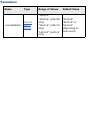
Description
This command selects the units (°C, °F, or Kelvins) to be used for
temperature measurements. The 34410A/11A/L4411A uses the selected
unit for temperature measurements regardless of the transducer selection
(thermistor, or 2-wire or 4-wire RTD).
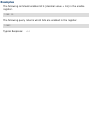
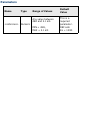
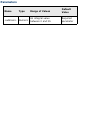
Parameters
Name
Type
Range of Values
Default Value
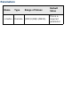
<units>
Discrete
{C|F|K}
Required
parameter.
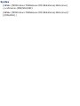
Remarks
The command also accepts "CEL" or "FAR" for the units parameter, but the
query returns "C" or "F".
The temperature unit selection is stored in volatile memory. The selection
is set to °C after a Factory Reset (*RST command) or an Instrument Preset
(SYSTem:PRESet command).
Return Format
The query command returns "C", "F", or "K".
Examples
The following command sets the temperature units to °F.
UNIT:TEMP F
The following query returns the temperature unit selected.
UNIT:TEMP?
Typical Response:
F
See Also
CONFigure:TEMPerature
MEASure:TEMPerature?
CALCulate Subsystem Introduction
The Agilent 34410A, 34411A, and L4411A can store readings in memory and
perform several mathematical, statistical, and limit calculation functions using
the CALCulate commands.
Command Summary
Select and Enable Functions
CALCulate:FUNCtion
CALCulate:FUNCtion)" href="Limits/CALCulate_LIMit_LOWer.htm">?
CALCulate:STATe
CALCulate:STATe?
Limit Functions
CALCulate:LIMit:LOWer
CALCulate:LIMit:LOWer?
CALCulate:LIMit:UPPer
CALCulate:LIMit:UPPer?
Mathematical Functions
CALCulate:DB:REFerence
CALCulate:DB:REFerence?
CALCulate:DBM:REFerence
CALCulate:DBM:REFerence?
CALCulate:NULL:OFFSet
CALCulate:NULL:OFFSet?
Statistical Functions
CALCulate:AVERage:AVERage?
CALCulate:AVERage:CLEar
CALCulate:AVERage:COUNt?
CALCulate:AVERage:MAXimum?
CALCulate:AVERage:MINimum?
CALCulate:AVERage:PTPeak?
CALCulate:AVERage:SDEViation?
CALCulate:FUNCtion
Syntax | Description | Parameters | Remarks | Return Format | Examples
Syntax
CALCulate:FUNCtion {NULL | DB | DBM | AVERage | LIMit}
CALCulate:FUNCtion?
Description
This command selects the calculation function to be used. The default
function is NULL.
The null function provided in this command is for compatibility with
the 34401A 6½ Digit Multimeter. For the 34410A, 34411A,L4411A
it is recommended that you use the individual (null per function)
null commands found in the [SENSe:] subsystem, rather than the
null function provided by the CALCulate:NULL:OFFSet command.
Avoid using both types of nulls, as unexpected results may occur
(they are additive).
Remarks
Send CALCulate:FUNCtion AVERage to enable statistics. When statistics
are enabled, the average (mean), minimum, maximum, peak-to-peak,
count, and standard deviation values are calculated and carried in the
statistical data registers, available to be read with the statistics
(CALCulate:AVERage) commands such as CALCulate:AVERage:AVERage?
and CALCulate:AVERage:SDEViation?.
The CALCulate subsystem (math operations) must be enabled using the
CALCulate:STATe command.
The instrument clears the calculation function selection, reverting to the
default after a Factory Reset (*RST command) or an Instrument Preset
(SYSTem:PRESet command).
Return Format
The query returns the currently selected function: NULL, DB, DBM, AVER, or
LIM.
Examples
The following command sets the function to be calculated to DBM.
CALC:FUNC DBM
The following query returns the currently enabled calculation function.
CALC:FUNC?
Typical Response:
DBM
See Also
CALCulate:STATe
CALCulate:STATe
Syntax | Description | Parameters | Remarks | Return Format | Examples
Syntax
CALCulate[:STATe] {OFF | ON}
CALCulate:STATe?
Description
This command turns the CALCulate subsystem, and thus the selected
calculation function, on or off.
Remarks
The calculation function to be used is selected using the
CALCulate:FUNCtion command.
CALCulate:STATe is set to OFF when the measurement function is
changed.
When CALCulate:STATe:ON is sent the math registers for limits, statistics,
dB relative value, and the value set by CALCulate:NULL:OFFSet are
cleared. This also occurs when CALCulate:FUNCtion is sent with
CALCulate:STATe previously set to ON. Note that the dBm reference
resistance value is not cleared in either case.
The instrument resets the calculation state to off after a Factory Reset
(*RST command), an Instrument Preset (SYSTem:PRESet command), or a
function change.
Return Format
The query returns the current calculation state: "0" (OFF) or "1" (ON).
Example
The following command sets the calculation state to "ON".
CALC:STAT ON
The following query returns the current calculation state.
CALC:STAT?
Typical Response:
"1"
See Also
CALCulate:FUNCtion
CALCulate:LIMit:LOWer
Syntax | Description | Parameters | Remarks | Return Format | Examples
Syntax
CALCulate:LIMit:LOWer {<value> | MINimum | MAXimum}
CALCulate:LIMit:LOWer? {MINimum | MAXimum}
Description
This command sets the lower limit for the present measurement function
(used in limit testing).
Parameters
The <value> parameter can take any value between -120% and +120% of
the highest (maximum) range for the currently selected function The
<value> is entered in the fundamental units for the function (that is volts,
ohms, farads, and so forth). MIN = -120% and MAX = +120%. Default = 0.
For example, if dc voltage is the selected measurement, the highest range is
1000 volts, and the MAX value is 120% of that: 1200 volts.
Remarks
You must select the limit math function (CALC:FUNC LIM) and turn on
math operations (CALC:STAT ON) before you set a limit value.
You can assign a lower limit, an upper limit (see CALCulate:LIMit:UPPer
command), or both. The lower limit must always be less than or equal to
the upper limit, even if you are using only one of the limits.
Limit crossing: If a reading is less than the specified lower limit, bit 11
("Lower Limit Failed") is set in the Questionable Data Register, which
results in an SRQ if enabled. You can use the
STATus:QUEStionable[:EVENt]? command to read the event register. See
STATus Subsystem Introduction for further information.
The instrument clears all limits after a Factory Reset (*RST command) or
an Instrument Preset (SYSTem:PRESet command), or when the math
function or measurement function is changed.
Return Format
The query command returns the lower limit in the form "-1.00000000E+03".
Examples
The following command sets the lower limit to -0.25.
CALC:LIM:LOW -0.25
The following query returns the lower limit setting.
CALC:LIM:LOW?
Typical Response:
-2.50000000E-01
See Also
CALCulate:FUNCtion
CALCulate:LIMit:UPPer
CALCulate:STATe
STATus Subsystem Introduction
CALCulate:LIMit:UPPer
Syntax | Description | Parameters | Remarks | Return Format | Examples
Syntax
CALCulate:LIMit:UPPer {<value> | MINimum | MAXimum}
CALCulate:LIMit:UPPer? {MINimum | MAXimum}
Description
This command sets the upper limit for the present measurement function
(used in limit testing).
Parameters
The <value> parameter can take any value between -120% and +120% of
the highest (maximum) range for the currently selected function The
<value> is entered in the fundamental units for the function (that is volts,
ohms, farads, and so forth). MIN = -120% and MAX = +120%. Default = 0.
For example, if dc voltage is the selected measurement, the highest range is
1000 volts, and the MAX value is 120% of that: 1200 volts.
Remarks
You must select the limit math function (CALC:FUNC LIM) and turn on
math operations (CALC:STAT ON) before you set a limit value.
You can assign a lower limit, an upper limit (see CALCulate:LIMit:UPPer
command), or both. The lower limit must always be less than or equal to
the upper limit, even if you are using only one of the limits.
Limit crossing: If a reading is greater than the specified upper limit, bit 12
("Upper Limit Failed") is set in the Questionable Data Register, which
results in an SRQ if enabled. You can use the
STATus:QUEStionable[:EVENt]? command to read the event register. See
STATus Subsystem Introduction for further information.
The instrument clears all limits after a Factory Reset (*RST command) or
an Instrument Preset (SYSTem:PRESet command), or when the math
function or measurement function is changed.
Return Format
The query command returns the upper limit in the form "+1.00000000E+03".
Examples
The following command sets the upper limit to 10.25.
CALC:LIM:UPP 10.25
The following query returns the limit settings.
CALC:LIM:UPP?
Typical Response:
+1.02500000E+01
See Also
CALCulate:FUNCtion
CALCulate:LIMit:LOWer
CALCulate:STATe
STATus Subsystem Introduction
CALCulate:DB:REFerence
Syntax | Description | Parameters | Remarks | Return Format | Examples
Syntax
CALCulate:DB:REFerence {<value> | MINimum | MAXimum}
CALCulate:DB:REFerence? {MINimum | MAXimum}
Description
This command stores a relative value in the meter's dB Relative Register,
which is used for the dB function in the CALCulate:FUNCtion command.
Parameters
The <value> (relative value) parameter can take any value in the range
±200 dBm.
MIN = -200.00 dBm. MAX = +200.00 dBm. The default value is 0 dBm.
Remarks
You must select (CALCulate:FUNCtion) and turn on (CALCulate:STATe)
math operations before writing to the dB Relative Register.
The dB relative value parameter is relative to the dBm reference set with
the CALCulate:DBM:REFerence command.
The instrument resets the dB relative value to the default after a Factory
Reset (*RST command) or an Instrument Preset (SYSTem:PRESet
command), or when the math function or measurement function is
changed.
Return Format
The query command returns the relative value in the form
"+1.00000000E+02".
Examples
The following command sets the dB relative value to -10.0 dBm.
CALC:DB:REF -10.0
The following query returns the dB relative value.
CALC:DB:REF?
Typical Response:
-1.00000000E+01
See Also
CALCulate:DBM:REFerence
CALCulate:FUNCtion
CALCulate:STATe
CALCulate:DBM:REFerence
Syntax | Description | Parameters | Remarks | Return Format | Examples
Syntax
CALCulate:DBM:REFerence {<value> | MINimum | MAXimum}
CALCulate:DBM:REFerence? {MINimum | MAXimum}
Description
This command selects the dBm reference resistance. The default is 600
ohms. This reference value affects both the dBm and dB functions in the
CALCulate:FUNCtion command.
Parameters
The <value> (dBm reference value) parameter can only take on certain
discrete values. Choose from: 50, 75, 93, 110, 124, 125, 135, 150, 250,
300, 500, 600, 800, 900, 1000, 1200, or 8000 ohms. MIN = 50 ohms. MAX
= 8000 ohms. The default value is 600 ohms.
Remarks
The dBm reference resistance is not reset when math functions are
enabled by the CALCulate:STATe command, nor when a
CALCulate:FUNCtion command is sent with CALCulate:STATe set to ON.
The dBm reference resistance value is stored in non-volatile memory. It is
not affected by a power-on cycle, Factory Reset (*RST command),
Instrument Preset (SYSTem:PRESet command), or function change.
Return Format
The query command returns the dBm reference resistance.
Examples
The following command sets the dBm reference resistance to 300 ohms.
CALC:DBM:REF 300
The following query returns the dBm reference resistance.
CALC:DBM:REF?
Typical Response:
+3.00000000E+02
See Also
CALCulate:DB:REFerence
CALCulate:FUNCtion
CALCulate:STATe
CALCulate:NULL:OFFSet
Syntax | Description | Parameters | Remarks | Return Format | Examples
Syntax
CALCulate:NULL:OFFSet {<value> | MINimum | MAXimum}
CALCulate:NULL:OFFSet? {MINimum | MAXimum}
Description
This command stores a null value in the multimeter's Null Register.
This command is provided for compatibility with the 34401A 6½
Digit Multimeter. For the 34410A, 34411A, or L4411A it is
recommended that you use the individual (null per function) null
commands found in the [SENSe:] subsystem, rather than the null
function provided by the CALCulate:NULL:OFFSet command. Avoid
using both types of nulls, as unexpected results may occur (they
are additive).
Parameters
The <value> parameter can take any value between -120% and +120% of
the highest range for the present measurement function. MIN = -120% of
the highest range. MAX = +120% of the highest range. The default value is
0.
Remarks
If you use the individual (null per function) null commands found in the
[SENSe:] subsystem, it is recommended that you not use this function,
and that you not turn on the null state with the CALC:FUNC command. If
you do, the measurement function null, set with the [SENSe:] command,
and the null set with the CALC:NULL:OFFS command, are additive.
You must select (CALCulate:FUNCtion) and turn on (CALCulate:STATe)
math operations before you set a null value.
If a null offset value is not specified with the CALC:NULL:OFFS command,
the first measurement taken is used as the null value.
The instrument clears the null value after a Factory Reset (*RST
command), after an Instrument Preset (SYSTem:PRESet command), when
the math function or measurement function is changed, or when
CALCulate:STATe ON is sent.
Return Format
The query command returns the null value in the form "+1.00000000E-02".
Examples
The following command sets the null value to -0.25.
CALC:NULL:OFFS -0.25
The following query returns the null value.
CALC:NULL:OFFS?
Typical Response:
-2.50000000E-01
See Also
CALCulate:STATe
CALCulate:AVERage:AVERage?
Syntax | Description | Parameters | Remarks | Return Format | Example
Syntax
CALCulate:AVERage:AVERage?
Description
This command returns the mathematical average (mean) of all readings
taken since statistics were enabled.
Remarks
You can read the statistical values at any time.
The instrument clears the stored statistical data when statistics are
enabled, when the CALCulate:FUNCtion command is sent while
CALCulate:STATe is ON, when the power has been off, when the
CALCulate:AVERage:CLEar command is executed, after a Factory Reset
(*RST command), after an Instrument Preset (SYSTem:PRESet command),
or after a function change.
Return Format
The command returns the average of the readings taken, or "0" if no data is
available.
Example
The following query returns the average of the readings taken.
CALC:AVER:AVER?
Typical Response:
+2.61920000E+01
See Also
CALCulate:AVERage:CLEar
CALCulate:AVERage:COUNt?
CALCulate:FUNCtion
CALCulate:STATe
CALCulate:AVERage:CLEar
Syntax | Description | Parameters | Remarks | Return Format | Example
Syntax
CALCulate:AVERage:CLEar
Description
This command clears all values from the statistics register.
Remarks
This command clears the minimum, maximum, average, count, and
standard deviation values (but no readings are cleared from memory).
The instrument also clears the stored statistical data when statistics are
enabled, when the CALCulate:FUNCtion command is sent while
CALCulate:STATe is ON, when the power has been off, when the
CALCulate:AVERage:CLEar command is executed, after a Factory Reset
(*RST command), after an Instrument Preset (SYSTem:PRESet command),
or after a function change.
Return Format
This command has no query form.
Example
The following command clears the stored statistical data.
CALC:AVER:CLE
See Also
CALCulate:AVERage:AVERage?
CALCulate:AVERage:COUNt?
CALCulate:AVERage:MAXimum?
CALCulate:AVERage:MINimum?
CALCulate:AVERage:PTPeak?
CALCulate:AVERage:SDEViation?
CALCulate:STATe
CALCulate:AVERage:COUNt?
Syntax | Description | Parameters | Remarks | Return Format | Example
Syntax
CALCulate:AVERage:COUNt?
Description
This command returns the number of readings taken since statistics were
enabled.
Remarks
You can read the statistical values at any time.
The instrument clears the stored statistical data when statistics are
enabled, when an INITiate command is sent, when the
CALCulate:FUNCtion command is sent while CALCulate:STATe is ON, when
the power has been off, when the CALCulate:AVERage:CLEar command is
executed, after a Factory Reset (*RST command), after an Instrument
Preset (SYSTem:PRESet command), or after a function change.
Return Format
The command returns the count since statistics were enabled. If no data is
available , "0" is returned.
Example
The following query returns the number of readings taken since statistics
were enabled.
CALC:AVER:COUN?
Typical Response:
+2.0000000E+01
See Also
CALCulate:AVERage:CLEar
CALCulate:FUNCtion
CALCulate:STATe
CALCulate:AVERage:MAXimum?
Syntax | Description | Parameters | Remarks | Return Format | Example
Syntax
CALCulate:AVERage:MAXimum?
Description
This command returns the maximum value found since statistics were
enabled.
Remarks
You can read the statistical values at any time.
The instrument clears the stored statistical data when statistics are
enabled, when the CALCulate:FUNCtion command is sent while
CALCulate:STATe is ON, when the power has been off, when the
CALCulate:AVERage:CLEar command is executed, after a Factory Reset
(*RST command), after an Instrument Preset (SYSTem:PRESet command),
or after a function change.
Return Format
The command returns the maximum of the readings taken, or "0" if no data
is available.
Example
The following query returns the maximum value found.
CALC:AVER:MAX?
Typical Response:
+1.37370000E+03
See Also
CALCulate:AVERage:CLEar
CALCulate:AVERage:COUNt?
CALCulate:FUNCtion
CALCulate:STATe
CALCulate:AVERage:MINimum?
Syntax | Description | Parameters | Remarks | Return Format | Example
Syntax
CALCulate:AVERage:MINimum?
Description
This command returns the minimum value found since statistics were
enabled.
Remarks
You can read the statistical values at any time.
The instrument clears the stored statistical data when statistics are
enabled, when the CALCulate:FUNCtion command is sent while
CALCulate:STATe is ON, when the power has been off, when the
CALCulate:AVERage:CLEar command is executed, after a Factory Reset
(*RST command), after an Instrument Preset (SYSTem:PRESet command),
or after a function change.
Return Format
The command returns the minimum value found, or "0" if no data is
available.
Example
The following query returns the minimum value found.
CALC:AVER:MIN?
Typical Response:
+4.27150000E-03
See Also
CALCulate:AVERage:CLEar
CALCulate:AVERage:COUNt?
CALCulate:FUNCtion
CALCulate:STATe
CALCulate:AVERage:PTPeak?
Syntax | Description | Parameters | Remarks | Return Format | Example
Syntax
CALCulate:AVERage:PTPeak?
Description
This command returns the peak-to-peak value of all readings taken since
statistics were enabled.
Remarks
You can read the statistical values at any time.
This function returns the statistical peak-to-peak value for a collection of
readings (since statistics were enabled). This is different than the 2nd
Display peak-to-peak measurement, which measures high and low peaks
over a single measurement aperture.
The instrument clears the stored statistical data when statistics are
enabled, when the CALCulate:FUNCtion command is sent while
CALCulate:STATe is ON, when the power has been off, when the
CALCulate:AVERage:CLEar command is executed, after a Factory Reset
(*RST command), after an Instrument Preset (SYSTem:PRESet command),
or after a function change.
Return Format
The command returns the peak-to-peak value of all readings taken since
statistics were enabled. If no data is available, "0" is returned.
Example
The following query returns the peak-to-peak value of the readings taken.
CALC:AVER:PTP?
Typical Response:
+1.34560000E+00
See Also
CALCulate:AVERage:CLEar
CALCulate:AVERage:COUNt?
CALCulate:FUNCtion
CALCulate:STATe
CALCulate:AVERage:SDEViation?
Syntax | Description | Parameters | Remarks | Return Format | Example
Syntax
CALCulate:AVERage:SDEViation?
Description
This command returns the standard deviation of all readings taken since
statistics were enabled.
Remarks
You can read the statistical values at any time.
The instrument clears the stored statistical data when statistics are
enabled, when the CALCulate:FUNCtion command is sent while
CALCulate:STATe is ON, when the power has been off, when the
CALCulate:AVERage:CLEar command is executed, after a Factory Reset
(*RST command), after an Instrument Preset (SYSTem:PRESet command),
or after a function change.
Return Format
The command returns the standard deviation of the readings taken, or "0" if
no data is available.
Example
The following query returns the standard deviation of the readings taken.
CALC:AVER:SDEV?
Typical Response:
+2.61920000E+01
See Also
CALCulate:AVERage:CLEar
CALCulate:AVERage:COUNt?
CALCulate:FUNCtion
CALCulate:STATe
CALibration Subsystem Introduction
The CALibration commands are used to calibrate the Agilent 34410A, 34411A,
and L4411A. Please note that the use of these commands requires a detailed
knowledge of the appropriate calibration procedures, which are described in
the Agilent 34410A/11A/L4411A Service Guide. Please refer to that guide
before attempting to calibrate the instrument. Improper use of the CALibration
commands can adversely affect the accuracy and reliability of the instrument.
Command Summary
CALibration[:ALL]?
CALibration:ADC?
CALibration:COUNt?
CALibration:LFRequency
CALibration:LFRequency?
CALibration:LFRequency:ACTual?
CALibration:SECure:CODE
CALibration:SECure:STATe
CALibration:SECure:STATe?
CALibration:STRing
CALibration:STRing?
CALibration:STORe
CALibration:VALue
CALibration:VALue?
CALibration:ADC?
Syntax | Description | Parameters | Remarks | Return Format | Example
Syntax
CALibration:ADC?
Description
This command performs a low-level calibration of the ADC (analog-to-digital
converter) circuitry.
For a more detailed discussion of the calibration procedures, see
the Agilent 34410A/11A/L4411A Service Guide. Please refer to the
Service Guide before attempting to calibrate the instrument.
Improper use of the CALibration commands can adversely affect the
accuracy and reliability of the instrument.
Remarks
This is the first step in a re-calibration sequence, and must be done before
doing the offset calibration.
Return Format
The command returns "0" if successful, "1" if not successful.
Example
The following command calibrates the ADC.
CAL:ADC?
Typical Response:
0
See Also
CALibration?
CALibration:SECure:STATe
CALibration[:ALL]?
Syntax | Description | Parameters | Remarks | Return Format | Example
Syntax
CALibration[:ALL]?
Description
This command performs a calibration of the multimeter using the specified
calibration value (CALibration:VALue command). Before you can calibrate
the instrument, you must unsecure it by entering the correct security code.
For a more detailed discussion of the calibration procedures, see
the Agilent 34410A/11A/L4411A Service Guide. Please refer to the
Service Guide before attempting to calibrate the instrument.
Improper use of the CALibration commands can adversely affect the
accuracy and reliability of the instrument.
Remarks
If a calibration fails, "+1" is returned and an error is stored in the error
queue. For a complete listing of the error messages related to calibration
failures, see SCPI Error Messages.
This command increments the calibration count on the 34410A, 34411A,
or L4411A (see CALibration:COUNt? command).
Return Format
The command returns "+0" (calibration passed) or "+1" (calibration failed).
Example
The following command performs a calibration and returns a pass/fail
indication.
CAL?
Typical Response:
+0
See Also
CALibration:SECure:STATe
CALibration:VALue
CALibration:COUNt?
Syntax | Description | Parameters | Remarks | Return Format | Example
Syntax
CALibration:COUNt?
Description
This command queries the instrument to determine how many calibrations
have been performed. Note that your instrument was calibrated before it left
the factory. When you receive your instrument, be sure to read the count to
determine the initial values.
For a more detailed discussion of the calibration procedures, see
the Agilent 34410A/11A/L4411A Service Guide. Please refer to the
Service Guide before attempting to calibrate the instrument.
Improper use of the CALibration commands can adversely affect the
accuracy and reliability of the instrument.
Remarks
The calibration counts increment up to a maximum of over four billion
(232 - 1) after which they roll over to "0". Since the value increments by
one for each calibration point, a complete calibration may increase the
value by many counts. However, it is unlikely that the count will ever roll
over due to the high maximum.
The calibration count is incremented by the CALibration? command. You
can read the calibration count whether the instrument is secured or
unsecured.
The calibration count is stored in non-volatile memory, and does not
change when power has been off, after a Factory Reset (*RST command),
or after an Instrument Preset (SYSTem:PRESet command).
Return Format
The command returns the calibration count indicating how many calibrations
have been performed.
Example
The following command returns the calibration count.
CAL:COUN?
Typical Response:
+739
See Also
CALibration?
CALibration:SECure:STATe
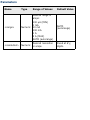
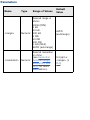
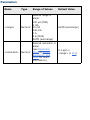
CALibration:LFRequency
Syntax | Description | Parameters | Remarks | Return Format | Example
Syntax
CALibration:LFRequency <line_freq>
CALibration:LFRequency?
Description
The query returns the power-line reference frequency currently used by the
34410A/11A/L4411A analog-to-digital converter (50 or 60 Hz). When you
apply power to the instrument, the instrument automatically detects the
power-line frequency and uses this value to determine the integration time
used.
The command form allows you to override automatic detection and set
either 50 or 60 Hz. However, it is recommended that you use automatic
detection to ensure that the calibration is performed with the reference
frequency set to the line frequency in use. In special cases, the dominant
noise source in the operating environment may be at the other frequency
(or harmonic thereof) and an override may be appropriate.
For a more detailed discussion of the calibration
procedures, see the Agilent 34410A/11A/L4411A
Service Guide. Please refer to the Service Guide before
attempting to calibrate the instrument. Improper use of
the CALibration commands can adversely affect the
accuracy and reliability of the instrument.
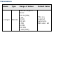
Parameters
Name
<line_freq>
Type
Range of Values
Default Value
Numeric
50 (50 Hz or 400
Hz)
60 (60 Hz)
Defaults to
sensed line
frequency
Remarks
The instrument multiplies the period of the reference frequency by the
specified number of power line cycles ([SENSe:]<function>:NPLC
commands) to determine the actual integration time.
The reference frequency setting is stored in volatile memory and will be
lost when power is turned off. The instrument automatically detects the
power-line frequency (50 Hz, 60 Hz, or 400 Hz) at power-on.
If the instrument detects a 400 Hz power line frequency, the 50 Hz
reference frequency value is actually used (a subharmonic of 400 Hz).
Return Format
The query returns "+50" (for 50 Hz or 400 Hz) or "+60" (for 60 Hz)
indicating the present reference frequency setting.
Example
The following command sets the reference frequency to 60 Hz (overriding
automatic detection).
CAL:LFR 60
The following command returns the reference frequency setting.
CAL:LFR?
Typical Response:
+60
See Also
[SENSe:]<function>:NPLC
CALibration:LFRequency:ACTual
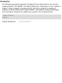
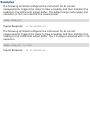
Syntax | Description | Parameters | Remarks | Return Format | Example
Syntax
CALibration:LFRequency:ACTual?
Description
This command returns the actual power-line frequency.
For a more detailed discussion of the calibration
procedures, see the Agilent 34410A/11A/L4411A
Service Guide. Please refer to the Service Guide before
attempting to calibrate the instrument. Improper use of
the CALibration commands can adversely affect the
accuracy and reliability of the instrument.
Remarks
The reference frequency used by the 34410A/11A/L4411A analog-todigital converter is based on the power line frequency measured at power
on. But, the reference frequency is set to either 50 Hz (for a power line
frequency of 50 Hz or 400 Hz), or 60 Hz (for a 60 Hz power line
frequency). The CALibration:LFRequency? command returns the reference
frequency (+50 or +60). The CALibration:LFRequency:ACTual? command
measures and returns the actual power line frequency.
This command does the same thing as the SYSTem:LFRequency:ACTual?
command.
Return Format
The command returns the actual power line frequency measured at power
up in the format "+5.99982241E+01".
Example
The following command returns the reference frequency setting.
CAL:LFR:ACT?
Typical Response:
+5.99982241E+01
See Also
CALibration:LFRequency
SYSTem:LFRequency:ACTual?
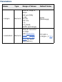
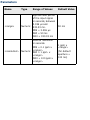
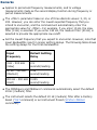
CALibration:SECure:CODE
Syntax | Description | Parameters | Remarks | Return Format | Example
Syntax
CALibration:SECure:CODE <new_code>
Description
This command allows you to enter a new security code to prevent accidental
or unauthorized calibrations. The specified code is used to unsecure
calibration memory. To change the security code, you must first unsecure
calibration memory using the old security code, and then enter a new code.
For a more detailed discussion of the calibration procedures, see
the Agilent 34410A/11A/L4411A Service Guide. Please refer to the
Service Guide before attempting to calibrate the instrument.
Improper use of the CALibration commands can adversely affect the
accuracy and reliability of the instrument.
Parameters
Name
<new_code>
Type
Range of Values
Default Value
Unquoted
ASCII
String
A string of up to 12
characters. You do not
have to use all 12
characters but the first
character must always
be a letter (A-Z). The
remaining 11
characters can be
letters, numbers (09), or the underscore
character ("_"). Blank
spaces are not
allowed.
This is a
required
parameter
Remarks
The security codes for the 34410A/11A/L4411A are set to "AT34410",
"AT34411", and "ATL4411" respectively when the instruments are
shipped from the factory.
If you forget your security code, you can override the security feature. See
the Agilent 34410A/11A/L4411A Service Guide for more information.
The security code is stored in non-volatile memory, and does not
change when power has been off, after a Factory Reset (*RST
command), or after an Instrument Preset (SYSTem:PRESet
command).
Example
The following command sets a new calibration security code (calibration
memory must be unsecured).
CAL:SEC:CODE T3ST_DUT165
See Also
CALibration:SECure:STATe
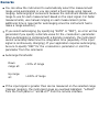
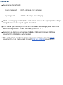
CALibration:SECure:STATe
Syntax | Description | Parameters | Remarks | Return Format | Examples
Syntax
CALibration:SECure:STATe <mode>, <code>
CALibration:SECure:STATe?
Description
This command unsecures or secures the instrument for calibration. To
unsecure the instrument, you must provide a security code to prevent
accidental or unauthorized calibrations of the instrument. Before you can
calibrate the instrument, you must unsecure it by entering the correct
security code.
For a more detailed discussion of the calibration procedures, see
the Agilent 34410A/11A/L4411A Service Guide. Please refer to the
Service Guide before attempting to calibrate the instrument.
Improper use of the CALibration commands can adversely affect the
accuracy and reliability of the instrument.
Parameters
Name
Type
Range of Values
Default Value
<mode>
Boolean
{OFF|0|ON|1}
This is a required
parameter.
Unquoted
ASCII
String
A string of up to 12
characters. You do not
have to use all 12
characters but the first
character must always
be a letter (A-Z). The
remaining 11 characters
can be letters, numbers
(0-9), or the underscore
character ("_"). Blank
spaces are not allowed.
This parameter is
required to
disable security,
but is optional to
enable security
(but must be
correct if
provided).
<code>
Remarks
When you first receive your instrument, it is secured. The security code is
set to "AT34410", "AT34411", or "ATL4411" when the instrument is
shipped from the factory.
Once you enter a security code, that code must be used for both frontpanel and remote-interface calibration. For example, if you secure the
instrument from the front panel, you must use that same code to unsecure
it from the remote interface.
Unsecuring the instrument using this command enables the instrument to
be calibrated.
To calibrate the 34410A, 34411A, or L4411A use the CALibration:VALue
and CALibration? commands.
The calibration security setting is stored in non-volatile memory,
and does not change when power has been off, after a Factory
Reset (*RST command), or after an Instrument Preset
(SYSTem:PRESet command).
Return Format
The query command returns "0" (OFF) or "1" (ON) indicating the current
calibration security setting.
Examples
The following command unsecures the instrument using the factory default
security code.
CAL:SEC:STAT OFF,AT34410
The following query returns the current calibration security setting.
CAL:SEC:STAT?
Typical Response:
0
See Also
CALibration:SECure:CODE
CALibration:STRing
Syntax | Description | Parameters | Remarks | Return Format | Examples
Syntax
CALibration:STRing "<string>"
CALibration:STRing?
Description
This command allows you to store one message in calibration memory. For
example, you can store such information as the date when the last
calibration was performed, the date when the next calibration is due, the
instrument's serial number, or even the name and phone number of the
person to contact for a new calibration.
For a more detailed discussion of the calibration procedures, see
the Agilent 34410A/11A/L4411A Service Guide. Please refer to the
Service Guide before attempting to calibrate the instrument.
Improper use of the CALibration commands can adversely affect the
accuracy and reliability of the instrument.
Parameters
Name
<string>
Type
Quoted
ASCII
String
Range of Values
Default Value
A string of up to 40
characters enclosed in
quotes. You can use
letters (A-Z), numbers
(0-9), and special
characters like "@",
"%", "*", etc.
This is a
required
parameter
Remarks
You can record a calibration message only from the remote interface and
only when the instrument is unsecured (see
CALibration:SECure:STATe OFF command). You can read the message
from either the front-panel or over the remote interface. You can read the
calibration message whether the instrument is secured or unsecured.
The calibration message may contain up to 40 characters. From the front
panel, you can view only 18 characters of the message at a time. Press [>]
to scroll through the text of the message. Press [>] again to increase the
scrolling speed.
From the front panel, commas, periods, and semicolons share a display
space with the preceding character, and are not considered individual
characters.
Storing a calibration message will overwrite any message previously stored
in memory.
The calibration message is stored in non-volatile calibration memory, and
does not change when power has been off, after a Factory Reset (*RST
command), or after an Instrument Preset (SYSTem:PRESet command).
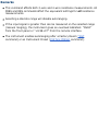
Return Format
The query command returns an ASCII string enclosed in double quotes. If no
calibration message has been specified, an empty quoted string ("") is
returned.
Examples
The following commands store a message in calibration memory.
CAL:STR "CAL: 21 Nov 2005"
or
CAL:STR 'CAL: 21 Nov 2005'
The following query returns the message currently stored in calibration
memory (the quotes are also returned).
CAL:STR?
Typical Response:
"CAL: 21 Nov 2005"
See Also
CALibration:SECure:STATe
CALibration:STORe
Syntax | Description | Parameters | Remarks | Return Format | Examples
Syntax
CALibration:STORe
Description
This command stores the calibration constants in non-volatile memory.
For a more detailed discussion of the calibration procedures, see
the Agilent 34410A/11A/L4411A Service Guide. Please refer to the
Service Guide before attempting to calibrate the instrument.
Improper use of the CALibration commands can adversely affect the
accuracy and reliability of the instrument.
Remarks
The CALibration:ADC? and CALibration[:ALL]? commands modify the
volatile versions of the calibration constants. You must use the
CALibration:STORe command to save these constants in non-volatile
memory at the end of your calibration, or the changes will be lost.
Once the calibration constants are stored in non-volatile calibration
memory, they will not change when power has been off, after a Factory
Reset (*RST command), or after an Instrument Preset (SYSTem:PRESet
command).
Examples
The following command stores the calibration constants in non-volatile
calibration memory.
CAL:STOR
See Also
CALibration:ADC?
CALibration[:ALL]?
CALibration:SECure:STATe
CALibration:VALue
Syntax | Description | Parameters | Remarks | Return Format | Examples
Syntax
CALibration:VALue <value>
CALibration:VALue?
Description
This command specifies the value of the known calibration signal as outlined
in the calibration procedures in the Agilent 34410A/11A/L4411A Service
Guide.
For a more detailed discussion of the calibration procedures, see
the Agilent 34410A/11A/L4411A Service Guide. Please refer to the
Service Guide before attempting to calibrate the instrument.
Improper use of the CALibration commands can adversely affect the
accuracy and reliability of the instrument.
Parameters
Name
<value>
Type
Range of Values
Default Value
Numeric
Desired calibration
signal in the units
specified by the
present measurement
function.
This is a
required
parameter
Remarks
Refer to the Agilent 34410A/11A/L4411A Service Guide for detailed
procedures, including how to connect a calibration source, recommended
equipment, the specified calibration points, and so forth.
Return Format
The query command returns the calibration value in the form
"+1.00000000E-01".
Examples
The following command sets calibration value to +10.001010 volts.
CAL:VAL 10.001010
The following query returns the present calibration value.
CAL:VAL?
Typical Response:
+1.00010100E+01
See Also
CALibration[:ALL]?
CONFigure Subsystem Introduction
The CONFigure command provides the most concise way to program the
instrument for measurements. When you execute this command, the
instrument uses default values for the requested measurement configuration
(like the MEASure? command). However, the measurement is not
automatically started and you can change some measurement attributes
before actually initiating the measurement. This allows you to incrementally
change the instrument's configuration from the default conditions.
Use the INITiate or READ? command to initiate the measurement.
Command Summary
CONFigure:CAPacitance
CONFigure:CONTinuity
CONFigure:CURRent:AC
CONFigure:CURRent[:DC]
CONFigure:DIODe
CONFigure:FREQuency
CONFigure:FRESistance
CONFigure:PERiod
CONFigure:RESistance
CONFigure:TEMPerature
CONFigure[:VOLTage]:AC
CONFigure[:VOLTage][:DC]
CONFigure?
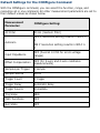
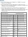
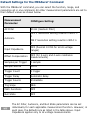
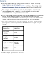
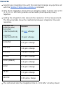
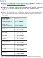
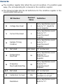
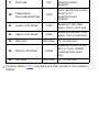
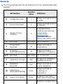
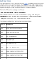
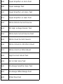
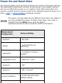
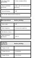
Default Settings for the CONFigure Command
With the CONFigure command, you can select the function, range, and
resolution all in one command. All other measurement parameters are set to
their default values as shown below.
Measurement
Parameter:
CONFigure Setting:
AC Filter
20 Hz (medium filter)
Autozero
OFF if resolution setting results in NPLC <
1
ON if resolution setting results in NPLC ≥
1
Input Impedance
OFF (fixed at 10 MΩ for all dc voltage
ranges)
Offset Compensation
OFF (for 2-wire and 4-wire resistance
measurements)
Samples per Trigger
1 sample
Sample Source
AUTO
Trigger Count
1 trigger
Trigger Delay
Automatic delay
Trigger Source
Immediate
Trig Slope
NEG
Math Functions
OFF
Null State
OFF
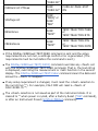
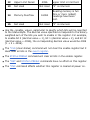
The AC Filter, Autozero, and Null State parameters can be set
individually for each applicable measurement function. However, in
each case, the defaults are as listed in the table above. Input
Impedance applies only to dc voltage measurements.
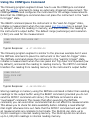
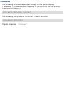
Using the CONFigure Command
The following program segment shows how to use the CONFigure command
with the READ? command to make an externally-triggered measurement. The
CONFigure command configures the instrument for dc voltage measurements.
Note that the CONFigure command does not place the instrument in the "waitfor-trigger" state.
The READ? command places the instrument in the "wait-for-trigger" state,
initiates a measurement when the rear-panel Ext Trig Inputline is pulsed (low
by default), stores the reading in memory, and then transfers the reading to
the instrument's output buffer. The default range (autorange) and resolution
(1 PLC) are used for the measurement.
CONF:VOLT:DC TRIG:SOUR EXT
READ?
Typical Response:
+4.27150000E-00
The following program segment is similar to the previous example but it uses
the INITiate command to place the instrument in the "wait-for-trigger" state.
The INITiate command places the instrument in the "wait-for-trigger" state,
initiates a measurement when the rear-panel Ext Trig Input line is pulsed (low
by default), and sends the reading to reading memory. The FETCh? command
transfers the reading from reading memory to the instrument's output buffer.
CONF:VOLT:DC
TRIG:SOUR EXT
INIT
FETC?
Typical Response:
+5.34250000E-00
Storing readings in memory using the INITiate command is faster than sending
readings to the output buffer using the READ? command (provided you do not
send the FETCh? command until done). The INITiate command is also an
"overlapped" command. This means that after executing the INITiate
command, you can send other commands that do not affect the measurements.
This allows you to check for data availability before initiating a read attempt
that might otherwise time out. Note that the FETCh? command will wait until
all measurements are complete to terminate. The 34410A can store up to
50,000 readings in internal reading memory. The 34411A/L4411A can store
up to 1,000,000 readings in internal reading memory.
The following program segment configures the instrument for 2-wire resistance
measurements, triggers the meter to make one measurement using the
INITiate, and then stores the reading in memory. The 10 kΩ range is selected
with 100Ω resolution.
CONF:RES 10000,100
INIT
FETC?
Typical Response:
+5.95850000E+03
CONFigure:CAPacitance
Syntax | Description | Parameters | Remarks | Return Format | Examples
Syntax
CONFigure:CAPacitance [{<range>|AUTO|MIN|MAX|DEF} [,
{<resolution>|MIN|MAX|DEF}]]
Description
First, this command resets all capacitance measurement parameters and
trigger parameters to their default values. Then, it configures the meter for
capacitance measurements but does not initiate the measurement.
The CONFigure command does not place the instrument in the "wait-fortrigger" state. Use the INITiate or READ? command in conjunction with
CONFigure to place the instrument in the "wait-for-trigger" state.
Parameters
Name
Type
Range of Values
Default
Value
Desired range in F
(farads):
<range>
Numeric
<resolution>
Numeric
1 nF (MIN)
10 nF
100 nF
1 µF
10 µF (MAX)
AUTO (autorange)
(DEF)
Desired resolution in
F (farads).
AUTO
Fixed at 4½
digits.
Remarks
The <resolution> parameter is optional, and is in fact ignored. The
resolution is actually fixed at 4½ digits.
You can allow the instrument to automatically select the measurement
range using autoranging or you can select a fixed range using manual
ranging. Autoranging is convenient because the instrument decides which
range to use for each measurement based on the input signal. For fastest
measurments, use manual ranging on each measurement (some additional
time may be required for autoranging since the instrument has to make a
range selection).
If you select autoranging (by specifying "AUTO" or "DEF"), an error will be
generated if you specify a discrete value for the <resolution> parameter.
When autoranging is combined with a discrete resolution, the instrument
cannot accurately resolve the integration time (especially if the input is
continuously changing). If your application requires autoranging, be sure
to specify "DEF" for the <resolution> parameter or omit the parameter
from the command.
Autorange thresholds:
Down
range at:
<10% of range
Up range
at:
>120% of range
If the input signal is greater than can be measured on the selected range
(manual ranging), the instrument gives an overload indication: "OVLD"
from the front panel or "+9.9E+37" from the remote interface.
Examples
The following program segment configures the instrument for capacitance
measurements. The READ? command places the instrument in the "wait-fortrigger" state, triggers a measurement, and then sends the reading to
memory and the instrument output buffer. The default range (AUTO) and
resolution (4½ digits) are used for the measurement.
CONF:CAP
READ?
Typical Response:
+0.04530000E-06
See Also
CONFigure?
FETCh?
INITiate[:IMMediate]
READ?
CONFigure:CONTinuity
Syntax | Description | Parameters | Remarks | Return Format | Examples
Syntax
CONFigure:CONTinuity
Description
First, this command resets all continuity measurement parameters and
trigger parameters to their default values. Then, it configures the meter for
continuity measurements but does not initiate a measurement. Continuity is
a special type of fixed-range 2-wire resistance measurement.
This command presets the meter to a fixed range and resolution, and then
configures for continuity tests. However, it does not initiate the test.
The CONFigure command does not place the instrument in the "wait-fortrigger" state. Use the INITiate or READ? command in conjunction with
CONFigure to place the instrument in the "wait-for-trigger" state.
Remarks
The range and resolution are fixed for continuity tests. The range is 1 kΩ
(a 2-wire resistance measurement).
The meter beeps (even if beep is disabled) for each measurement that is
less than or equal to the continuity threshold (≤10 Ω), and the actual
resistance reading is displayed on the front panel.
From 10 Ω to 1.2 kΩ the meter displays the actual resistance reading with
no beep.
If the reading exceeds 1.2 kΩ, the meter displays "OPEN" on the front
panel (no beep).
The FETCh?, READ?, and MEASure:CONTinuity? commands return the
measured resistance, regardless of its value.
Examples
The following program segment configures the instrument for continuity
measurements. The READ? command places the instrument in the "wait-fortrigger" state, triggers a measurement, and then sends the reading to
memory and the instrument output buffer.
CONF:CONT
READ?
Typical Response:
+1.32130000E-02
See Also
CONFigure?
FETCh?
INITiate[:IMMediate]
READ?
CONFigure:CURRent:AC
Syntax | Description | Parameters | Remarks | Return Format | Examples
Syntax
CONFigure:CURRent:AC [{<range>|AUTO|MIN|MAX|DEF} [,
{<resolution>|MIN|MAX|DEF}]]
Description
First, this command resets all ac current measurement parameters and
trigger parameters to their default values. Then, it configures the meter for
ac current measurements but does not initiate a measurement.
The CONFigure command does not place the instrument in the "wait-fortrigger" state. Use the INITiate or READ? command in conjunction with
CONFigure to place the instrument in the "wait-for-trigger" state.
Parameters
Name
Type
Range of Values
Default Value
Desired range in
amps:
<range>
Numeric
<resolution>
Numeric
100 µA (MIN)
1 mA
10 mA
100 mA
1A
3 A (MAX)
AUTO (autorange)
Desired resolution
in amps.
AUTO
(autorange)
Fixed at 6½
digits.
Remarks
The <resolution> parameter is optional, and is in fact ignored. The
resolution is actually fixed at 6½ digits.
You can allow the instrument to automatically select the measurement
range using autoranging or you can select a fixed range using manual
ranging. Autoranging is convenient because the instrument decides which
range to use for each measurement based on the input signal. For faster
measurements, use manual ranging on each measurement (some
additional time is required for autoranging since the instrument has to
make a range selection).
If you select autoranging (by specifying "AUTO" or "DEF"), an error will be
generated if you specify a discrete value for the <resolution> parameter.
When autoranging is combined with a discrete resolution, the instrument
cannot accurately resolve the integration time (especially if the input
signal is continuously changing). If your application requires autoranging,
be sure to specify "DEF" for the <resolution> parameter or omit the
parameter from the command.
Autorange thresholds:
Down
range at:
<10% of range
Up range
at:
>120% of range
If the input signal is greater than can be measured on the selected range
(manual ranging), the instrument gives an overload indication: "OVLD"
from the front panel or "9.9E+37" from the remote interface.
For ac measurements, the resolution is fixed at 6½ digits. To control the
reading rate for ac measurements, change the trigger delay, change the ac
filter bandwidth, or use the SAMPle:SOURce command and set the source
to TIMer.
Examples
The following program segment configures the instrument for ac current
measurements. The READ? command places the instrument in the "wait-fortrigger" state, triggers a measurement, and then sends the reading to
memory and the instrument output buffer. The default range (autorange)
and resolution (fixed at 6½ digits) are used for the measurement.
CONF:CURR:AC
READ?
Typical Response:
+8.54530000E-02
See Also
CONFigure?
FETCh?
INITiate[:IMMediate]
READ?
[SENSe:]CURRent:AC:BANDwidth
CONFigure:CURRent[:DC]
Syntax | Description | Parameters | Remarks | Return Format | Examples
Syntax
CONFigure:CURRent[:DC] [{<range>|AUTO|MIN|MAX|DEF} [,
{<resolution>|MIN|MAX|DEF}]]
Description
First, this command resets all dc current measurement parameters and
trigger parameters to their default values. Then, it configures the meter for
dc current measurements but does not initiate the measurement.
The CONFigure command does not place the instrument in the "wait-fortrigger" state. Use the INITiate or READ? command in conjunction with
CONFigure to place the instrument in the "wait-for-trigger" state.
Parameters
Name
Type
Range of Values
Default Value
Desired range in
amps:
<range>
<resolution>
Numeric
Numeric
100 µA (MIN)
1 mA
10 mA
100 mA
1A
3 A (MAX)
AUTO (autorange)
Desired resolution
in amps
(see Resolution
Table or Range,
Resolution, and
NPLC for more
information).
AUTO
(autorange)
0.3 ppm x
<range> (1 PLC)
Remarks
You can allow the instrument to automatically select the measurement
range using autoranging or you can select a fixed range using manual
ranging. Autoranging is convenient because the instrument decides which
range to use for each measurement based on the input signal. For faster
measurements, use manual ranging on each measurement (some
additional time is required for autoranging since the instrument has to
make a range selection).
If you select autoranging (by specifying "AUTO" or "DEF"), an error will be
generated if you specify a discrete value for the <resolution> parameter.
When autoranging is combined with a discrete resolution, the instrument
cannot accurately determine the integration time (especially if the input
signal is continuously changing). If your application requires autoranging,
be sure to specify "DEF" for the <resolution> parameter or omit the
parameter from the command.
Autorange thresholds:
Down
range at:
<10% of range
Up range
at:
>120% of range
If the input signal is greater than can be measured on the selected range
(manual ranging), the instrument gives an overload indication: "±OVLD"
from the front panel or "±9.9E+37" from the remote interface.
Examples
The following program segment configures the instrument for dc current
measurements. The READ? command places the instrument in the "wait-fortrigger" state, triggers a measurement, and then sends the reading to
memory and the instrument output buffer. The default range (autorange)
and resolution (1 PLC) are used for the measurement.
CONF:CURR:DC
READ?
Typical Response:
+8.54530000E-03
The following program segment configures the instrument for dc current
measurements. The INITiate command places the instrument in the "waitfor-trigger" state, triggers a measurement, and stores the reading in
memory. The FETCh? command transfers the reading from reading memory
to the instrument output buffer. The 1 A range is selected with 1 mA
resolution.
MEAS:CURR:DC? 1,0.001
INIT
FETC?
Typical Response:
+4.27150000E-02
See Also
CONFigure?
FETCh?
INITiate[:IMMediate]
READ?
[SENSe:]CURRent[:DC]:ZERO:AUTO
CONFigure:DIODe
Syntax | Description | Parameters | Remarks | Return Format | Examples
Syntax
CONFigure:DIODe
Description
First, this command resets all diode test parameters and trigger parameters
to their default values. Then it configures the meter for diode tests, but does
not initiate the test.
The CONFigure command does not place the instrument in the "wait-fortrigger" state. Use the INITiate or READ? command in conjunction with
CONFigure to place the instrument in the "wait-for-trigger" state.
Remarks
The range and resolution are fixed for diode tests: The range is 1 Vdc (with
a 1 mA current source output).
The voltage is displayed on the front panel if it is in the 0 to 1.2 volt
range. The meter beeps when the signal transitions to the 0.3 to 0.8 volt
threshold (unless beep is disabled). If the signal is greater than 1.2 volts,
"OPEN" is displayed on the front panel.
The FETCh?, READ?, and MEASure:DIODe? commands return the
measured voltage, regardless of its value.
Examples
The following program segment configures the instrument for diode tests.
The READ? command places the instrument in the "wait-for-trigger" state,
triggers a test, and then sends the reading to memory and the instrument
output buffer.
CONF:DIOD
READ?
Typical Response:
+1.32130000E-01
See Also
CONFigure?
FETCh?
INITiate[:IMMediate]
READ?
CONFigure:FREQuency
Syntax | Description | Parameters | Remarks | Return Format | Examples
Syntax
CONFigure:FREQuency [{<range>|MIN|MAX|DEF} [,
{<resolution>|MIN|MAX|DEF}]]
Description
First, this command resets all frequency measurement parameters and
trigger parameters to their default values. Then, it configures the meter for
frequency measurements but does not initiate the measurement.
The CONFigure command does not place the instrument in the "wait-fortrigger" state. Use the INITiate or READ? command in conjunction with
CONFigure to place the instrument in the "wait-for-trigger" state.
Parameters
Name
<range>
Type
Range of Values
Default Value
Numeric
Approximate
frequency of the
input signal
in hertz, between
3 Hz and 300 kHz.
20 Hz
MIN = 3 Hz
DEF = 20 Hz
MAX = 300 kHz
Desired resolution
in hertz.
<resolution>
Numeric
MIN = 0.1 ppm x
<range>
DEF = 1 ppm x
<range>
MAX = 100 ppm x
<range>
1 ppm x
<range>
(for default
aperture = 100
ms)
Remarks
Frequency is measured on ac voltage signals. Thus, the proper ac voltage
range should be set first using the
[SENSe:]FREQuency:VOLTage:RANGe[:UPPer] command. The voltage
range should be 0.1 volts or greater for more accurate frequency
measurements.
The <range> parameter is required only to specify the measurement
resolution parameter. Therefore, it is not necessary to send a new
command for each new frequency to be measured.
If the input signal voltage is greater than can be measured on the selected
voltage range (manual ranging), the instrument gives an overload
indication: "VAC OVERLOAD" from the front panel or "+9.9E+37" from the
remote interface. Autoranging can be enabled for the input voltage.
The frequency measurement does not autorange. For frequency
measurements, the range and resolution parameters affect the aperture
(gate time) as follows:
Resolution
Aperture
100 ppm x
<range>
1 ms
10 ppm x
<range>
10 ms
1 ppm x <range>
100 ms
(default)
0.1 ppm x
<range>
1s
With no signal applied "0" is returned.
Examples
The following program segment configures the instrument for frequency
measurements. The READ? command places the instrument in the "wait-fortrigger" state, triggers a measurement, and then sends the reading to
memory and the instrument output buffer. The default aperture (100 ms) is
used for the measurement.
CONF:FREQ
READ?
Typical Response:
+1.32130000E+03
The following program segment configures the instrument for frequency
measurements. The INITiate command places the instrument in the "waitfor-trigger" state, triggers a measurement, and stores the reading in
memory. The FETCh? command transfers the reading from reading memory
to the instrument's output buffer. The default aperture (100 ms) is used for
the measurement.
CONF:FREQ 100
INIT
FETC?
Typical Response:
+1.01230000E+02
See Also
CONFigure?
FETCh?
INITiate[:IMMediate]
READ?
[SENSe:]FREQuency:RANGe:LOWer
[SENSe:]FREQuency:VOLTage:RANGe[:UPPer]
CONFigure:FRESistance
Syntax | Description | Parameters | Remarks | Return Format | Examples
Syntax
CONFigure:FRESistance [{<range>|AUTO|MIN|MAX|DEF} [,
{<resolution>|MIN|MAX|DEF}]]
Description
First, this command resets all resistance measurement parameters and
trigger parameters to their default values. Then, it configures the meter for
4-wire resistance measurements but does not initiate the measurement.
The CONFigure command does not place the instrument in the "wait-fortrigger" state. Use the INITiate or READ? command in conjunction with
CONFigure to place the instrument in the "wait-for-trigger" state.
Parameters
Name
Type
Range of Values
Default
Value
Desired range in
ohms:
<range>
<resolution>
Numeric
Numeric
100Ω (MIN)
1 kΩ
10 kΩ
100 kΩ
1 MΩ
10 MΩ
100 MΩ
1 GΩ (MAX)
AUTO (autorange)
Desired resolution
in ohms
(see Resolution
Table or Range,
Resolution, and
NPLC for more
information).
AUTO
(autorange)
0.3 ppm x
<range> (1
PLC)
Remarks
You can allow the instrument to automatically select the measurement
range using autoranging or you can select a fixed range using manual
ranging. Autoranging is convenient because the instrument decides which
range to use for each measurement based on the input signal. For faster
measurements, use manual ranging on each measurement (some
additional time is required for autoranging since the instrument has to
make a range selection).
If you select autoranging (by specifying "AUTO" or "DEF"), an error will be
generated if you specify a discrete value for the <resolution> parameter.
When autoranging is combined with a discrete resolution, the instrument
cannot accurately resolve the integration time (especially if the input
signal is continuously changing). If your application requires autoranging,
be sure to specify "DEF" for the <resolution> parameter or omit the
parameter from the command.
Autorange thresholds:
Down
range at:
<10% of range
Up range
at:
>120% of range
If the input signal is greater than can be measured on the selected range
(manual ranging), the instrument gives an overload indication: "OVLD"
from the front panel or "+9.9E+37" from the remote interface.
For 4-wire measurements, the instrument always enables the autozero
function.
Examples
The following program segment configures the meter for a 4-wire resistance
measurement. The READ? command places the meter in the "wait-fortrigger" state, initiates a trigger, and then sends the reading to memory and
the instrument output buffer. The default range (autorange) and resolution
are used for the measurement.
CONF:FRES
READ?
Typical Response:
+2.93830000E+03
The following program segment configures the instrument for 4-wire
resistance measurements. The INITiate command places the instrument in
the "wait-for-trigger" state, triggers a measurement, and stores the reading
in memory. The FETCh? command transfers the reading from reading
memory to the instrument output buffer. The 1 kΩ range is selected with
0.1 Ω resolution.
CONF:FRES 1000,0.1
INIT
FETC?
Typical Response:
+4.27150000E+02
See Also
CONFigure:RESistance
CONFigure?
FETCh?
INITiate[:IMMediate]
READ?
[SENSe:]FRESistance:OCOMpensated
CONFigure:PERiod
Syntax | Description | Parameters | Remarks | Return Format | Examples
Syntax
CONFigure:PERiod [{<range>|MIN|MAX|DEF} [,
{<resolution>|MIN|MAX|DEF}]]
Description
First, this command resets all period measurement parameters and trigger
parameters to their default values. Then, it configures the meter for period
measurements but does not initiate the measurement.
The CONFigure command does not place the instrument in the "wait-fortrigger" state. Use the INITiate or READ? command in conjunction with
CONFigure to place the instrument in the "wait-for-trigger" state.
Parameters
Name
<range>
Type
Range of Values
Default Value
Numeric
Approximate period
of the input signal
in seconds, between
3.336 µs and
333.33 ms.
50 ms
MIN = 3.336 µs
DEF = 50 ms
MAX = 333.33 ms
Desired resolution
in seconds.
<resolution>
Numeric
MIN = 0.1 ppm x
<range>
DEF = 1 ppm x
<range>
MAX = 100 ppm x
<range>
1 ppm x
<range>
(for default
aperture =
100 ms)
Remarks
Period is measured on ac voltage signals. Thus, the proper ac voltage
range should be set first using the
[SENSe:]PERiod:VOLTage:RANGe[:UPPer] command. The voltage range
should be 0.1 volts or greater for more accurate period measurements.
The <range> parameter is required only to specify the measurement
resolution parameter. Therefore, it is not necessary to send a new
command for each new period to be measured.
If the input signal voltage is greater than can be measured on the selected
voltage range (manual ranging), the instrument gives an overload
indication: "VAC OVERLOAD" from the front panel or "+9.9E+37" from the
remote interface. Autoranging can be enabled for the input voltage.
The period measurement does not autorange. For period measurements,
the range and resolution parameters affect the aperture (gate time) as
follows:
Resolution
Aperture
100 ppm x
<range>
1 ms
10 ppm x
<range>
10 ms
1 ppm x <range>
100 ms
(default)
0.1 ppm x
<range>
1s
With no signal applied, "0" is returned.
Examples
The following program segment configures the instrument for period
measurements. The READ? command places the instrument in the "wait-fortrigger" state, triggers a measurement, and then sends the reading to
memory and the instrument output buffer. The default aperture (100 ms) is
used for the measurement.
CONF:PER
READ?
Typical Response:
+1.32130000E-03
The following program segment configures the instrument for period
measurements. The INITiate command places the instrument in the "waitfor-trigger" state, triggers a measurement, and stores the reading in
memory. The FETCh? command transfers the readings from reading memory
to the instrument's output buffer.
CONF:PER 0.001,0.0000001
INIT
FETC?
Typical Response:
+4.27150000E-04
See Also
CONFigure?
FETCh?
INITiate[:IMMediate]
READ?
[SENSe:]PERiod:VOLTage:RANGe[:UPPer]
CONFigure:RESistance
Syntax | Description | Parameters | Remarks | Return Format | Examples
Syntax
CONFigure:RESistance [{<range>|AUTO|MIN|MAX|DEF} [,
{<resolution>|MIN|MAX|DEF}]]
Description
First, this command resets all resistance measurement parameters and
trigger parameters to their default values. Then, it configures the meter for
2-wire resistance measurements but does not initiate the measurement.
The CONFigure command does not place the instrument in the "wait-fortrigger" state. Use the INITiate or READ? command in conjunction with
CONFigure to place the instrument in the "wait-for-trigger" state.
Parameters
Name
Type
Range of Values
Default
Value
Desired range in
ohms:
<range>
<resolution>
Numeric
Numeric
100Ω (MIN)
1 kΩ
10 kΩ
100 kΩ
1 MΩ
10 MΩ
100 MΩ
1 GΩ (MAX)
AUTO (autorange)
Desired resolution
in ohms
(see Resolution
Table or Range,
Resolution, and
NPLC for more
information).
AUTO
(autorange)
0.3 ppm x
<range> (1
PLC)
Remarks
You can allow the instrument to automatically select the measurement
range using autoranging or you can select a fixed range using manual
ranging. Autoranging is convenient because the instrument decides which
range to use for each measurement based on the input signal. For faster
measurements, use manual ranging on each measurement (some
additional time is required for autoranging since the instrument has to
make a range selection).
If you select autoranging (by specifying "AUTO" or "DEF"), an error will be
generated if you specify a discrete value for the <resolution> parameter.
When autoranging is combined with a discrete resolution, the instrument
cannot accurately resolve the integration time (especially if the input
signal is continuously changing). If your application requires autoranging,
be sure to specify "DEF" for the <resolution> parameter or omit the
parameter from the command.
Autorange thresholds:
Down
range at:
<10% of range
Up range
at:
>120% of range
If the input signal is greater than can be measured on the selected range
(manual ranging), the instrument gives an overload indication: "OVLD"
from the front panel or "+9.9E+37" from the remote interface.
Examples
The following program segment configures the instrument for 2-wire
resistance measurements. The READ? command places the instrument in the
"wait-for-trigger" state, triggers a measurement, and then sends the reading
to memory and the instrument output buffer. The default range (autorange)
and resolution (1 PLC) are used for the measurement.
CONF:RES
READ?
Typical Response:
+1.32130000E+04
The following program segment configures the instrument for 2-wire
resistance measurements. The INITiate command places the instrument in
the "wait-for-trigger" state, triggers a measurement, and stores the reading
in memory. The FETCh? command transfers the reading from reading
memory to the instrument output buffer. The 1 kΩ range is selected with
0.1 Ω resolution.
CONF:RES 1000,0.1
INIT
FETC?
Typical Response:
+4.27150000E+02
See Also
CONFigure:FRESistance
CONFigure?
FETCh?
INITiate[:IMMediate]
READ?
[SENSe:]RESistance:OCOMpensated
[SENSe:]RESistance:ZERO:AUTO
CONFigure:TEMPerature
Syntax | Description | Parameters | Remarks | Return Format | Examples
Syntax
CONFigure:TEMPerature [{<probe_type>|DEF}[,{<type>|DEF} [,1 [,
{<resolution>|MIN|MAX|DEF}]]]]
Description
First, this command resets all temperature measurement parameters and
trigger parameters to their default values. Then, it configures the meter for
temperature measurements but does not initiate the measurement.
The CONFigure command does not place the instrument in the "wait-fortrigger" state. Use the INITiate or READ? command in conjunction with
CONFigure to place the instrument in the "wait-for-trigger" state.
Parameters
Name
<probe_type>
Type
Discrete
Range of Values
Default
Value
{FRTD|RTD|FTHermistor|THERmistor}
Required
paramete
DEF sets
FRTD
For THER:
{2252|5000|10000}
Required
paramete
DEF sets
5000 (2wire)
{2252|5000|10000}
Required
paramete
DEF sets
5000 (4wire)
{85}
Required
paramete
DEF sets
85 (2wire)
{85}
Required
paramete
DEF sets
85 (4wire)
For FTH:
<type>
Discrete
For RTD:
For FRTD:
<resolution>
Numeric
Desired resolution in the currently
selected units (°C, °F, or K).
See Resolution Table.
0.3 ppm
<range>
(1 PLC)
Remarks
For temperature measurements, the instrument internally selects the
range−you cannot select the range to be used. The range ("1" is the only
allowed value) is used only in conjunction with resolution to determine
NPLC.
The range ("1") and <resolution> parameters are optional. However, if you
specify <resolution>, you must also specify "1" as the implied range
parameter (see syntax above). For example:
CONF:TEMP THER,5000,1,0.1
specifies range = 1 and resolution = 0.1 degrees (°C, °F, or K, whichever
is currently selected).
To change temperature units, use the UNIT:TEMPerature command.
For thermistor and RTD measurements, the instrument autoranges to the
correct range for the transducer resistance measurement.
For 4-wire RTD or thermistor measurements, the instrument always
enables the autozero function.
Examples
The following program segment configures the instrument for 5 kΩ, 2-wire
thermistor measurements. The INITiate command places the instrument in
the "wait-for-trigger" state, triggers a measurement, and stores the reading
in memory. The FETCh? command transfers the reading from reading
memory to the instrument output buffer. This 2-wire measurement is made
with 0.1 °C resolution (assumes default temperature units).
CONF:TEMP THER,5000,1,0.1
INIT
FETC?
Typical Response:
+2.47150000E+01
The following program segment configures the meter for a 2-wire RTD
measurement. The READ? command places the meter in the "wait-fortrigger" state, initiates a trigger, and then sends the reading to memory and
the instrument output buffer. The default resolution is used for the
measurement (assumes default temperature units).
CONF:TEMP RTD,85
READ?
Typical Response:
+2.12320000E+01
See Also
CONFigure?
FETCh?
INITiate[:IMMediate]
READ?
[SENSe:]TEMPerature:TRANsducer:TYPE
[SENSe:]TEMPerature:ZERO:AUTO
UNIT:TEMPerature
CONFigure[:VOLTage]:AC
Syntax | Description | Parameters | Remarks | Return Format | Examples
Syntax
CONFigure[:VOLTage]:AC [{<range>|AUTO|MIN|MAX|DEF} [,
{<resolution>|MIN|MAX|DEF}]]
Description
First, this command resets all ac voltage measurement parameters and
trigger parameters to their default values. Then, it configures the meter for
ac voltage measurements but does not initiate the measurement.
The maximum range parameter is 1000 V, which is set by
MAX. However, the SAFETY LIMIT on the front and rear
HI/LO input terminals is 750 VAC (rms). The rms voltage is
waveform dependent. A sine wave is limited to 750 VAC
(rms), but a 1000 Vpk square wave is safe. Connections to
AC MAINS are further limited to CAT II (300V). See the
"Safety Information" section in the Agilent
34410A/11A/L4411A User's Guide for a complete
discussion of the safety features, and the safe operation of
this instrument.
The CONFigure command does not place the instrument in the "wait-fortrigger" state. Use the INITiate or READ? command in conjunction with
CONFigure to place the instrument in the "wait-for-trigger" state.
Parameters
Name
Type
Range of Values
Default
Value
Desired range in
volts:
<range>
Numeric
<resolution>
Numeric
100 mV (MIN)
1V
10 V
100 V
1000 V (MAX)
AUTO (autorange)
Desired resolution
in volts.
AUTO
(autorange)
Fixed at 6½
digits.
Remarks
The <resolution> parameter is optional, and is in fact ignored. The
resolution is actually fixed at 6½ digits.
All ranges use the digital ac measurement technique.
You can allow the instrument to automatically select the measurement
range using autoranging or you can select a fixed range using manual
ranging. Autoranging is convenient because the instrument decides which
range to use for each measurement based on the input signal. For faster
measurements, use manual ranging on each measurement (some
additional time is required for autoranging since the instrument has to
make a range selection).
If you select autoranging (by specifying "AUTO" or "DEF"), an error will be
generated if you specify a discrete value for the <resolution> parameter.
When autoranging is combined with a discrete resolution, the instrument
cannot accurately resolve the integration time (especially if the input
signal is continuously changing). If your application requires autoranging,
be sure to specify "DEF" for the <resolution> parameter or omit the
parameter from the command.
Autorange thresholds:
Down
range at:
<10% of range
Up range
at:
>120% of range
If the input signal is greater than can be measured on the selected range
(manual ranging), the instrument gives an overload indication: "OVLD"
from the front panel or "+9.9E+37" from the remote interface.
For ac measurements, the resolution is fixed at 6½ digits. To control the
reading rate for ac measurements, change the trigger delay, change the ac
filter bandwidth, or use the SAMPle:SOURce command and set the source
to TIMer.
Examples
The following program segment configures the instrument for ac voltage
measurements. The READ? command places the instrument in the "wait-fortrigger" state, triggers a measurement, and then sends the reading to
memory and the instrument output buffer. The default range (autorange)
and resolution (fixed at 6½ digits) are used for the measurement.
CONF:VOLT:AC
READ?
Typical Response:
+1.86850000E+023
The following program segment configures the instrument for ac voltage
measurements. The INITiate command places the instrument in the "waitfor-trigger" state, triggers a measurement, and stores the reading in
memory. The FETCh? command transfers the reading from reading memory
to the instrument output buffer. The 1 V range is selected.
CONF:VOLT:AC 1
INIT
FETC?
Typical Response:
+4.27150000E-01
See Also
CONFigure?
FETCh?
INITiate[:IMMediate]
READ?
[SENSe:]VOLTage:AC:BANDwidth
CONFigure[:VOLTage][:DC]
Syntax | Description | Parameters | Remarks | Return Format | Examples
Syntax
CONFigure[:VOLTage][:DC] [{<range>|AUTO|MIN|MAX|DEF} [,
{<resolution>|MIN|MAX|DEF}]]
Description
First, this command resets all dc voltage measurement parameters and
trigger parameters to their default values. Then, it configures the meter for
dc voltage measurements but does not initiate the measurement.
The CONFigure command does not place the instrument in the "wait-fortrigger" state. Use the INITiate or READ? command in conjunction with
CONFigure to place the instrument in the "wait-for-trigger" state.
Parameters
Name
Type
Range of Values
Default
Value
Desired range in
volts:
<range>
<resolution>
Numeric
Numeric
100 mV (MIN)
1V
10 V
100 V
1000 V (MAX)
AUTO (autorange)
Desired resolution
in volts
(see Resolution
Table or Range,
Resolution, and
NPLC for more
information).
AUTO
(autorange)
0.3 ppm x
<range> (1
PLC)
Remarks
You can allow the instrument to automatically select the measurement
range using autoranging or you can select a fixed range using manual
ranging. Autoranging is convenient because the instrument decides which
range to use for each measurement based on the input signal. For faster
measurements, use manual ranging on each measurement (some
additional time is required for autoranging since the instrument has to
make a range selection).
If you select autoranging (by specifying "AUTO" or "DEF"), an error will be
generated if you specify a discrete value for the <resolution> parameter.
When autoranging is combined with a discrete resolution, the instrument
cannot accurately resolve the integration time (especially if the input
signal is continuously changing). If your application requires autoranging,
be sure to specify "DEF" for the <resolution> parameter or omit the
parameter from the command.
Autorange thresholds:
Down
range at:
<10% of range
Up range
at:
>120% of range
If the input signal is greater than can be measured on the selected range
(manual ranging), the instrument gives an overload indication: "±OVLD"
from the front panel or "±9.9E+37" from the remote interface.
Examples
The following program segment configures the instrument for dc voltage
measurements. The READ? command places the instrument in the "wait-fortrigger" state, triggers a measurement, and then sends the reading to
memory and the instrument output buffer. The default range (autorange)
and resolution (1 PLC) are used for the measurement.
CONF:VOLT:DC
READ?
Typical Response:
+1.86850000E-03
The following program segment configures the instrument for dc voltage
measurements. The INITiate command places the instrument in the "waitfor-trigger" state, triggers a measurement, and stores the reading in
memory. The FETCh? command transfers the reading from reading memory
to the instrument output buffer. The 1 V range is selected with 0.1 mV
resolution.
CONF:VOLT:DC 1,0.0001
INIT
FETC?
Typical Response:
+4.27150000E-01
See Also
CONFigure?
FETCh?
INITiate[:IMMediate]
READ?
[SENSe:]VOLTage[:DC]:ZERO:AUTO
CONFigure?
Syntax | Description | Parameters | Remarks | Return Format | Example
Syntax
CONFigure?
Description
This command returns the present instrument configuration as a quoted
string.
Remarks
Either the *RST command or the Instrument Preset (the SYSTem:PRESet
command) will set all measurement parameters to their factory settings,
clear reading memory, and clear all stored statistical data.
Return Format
The command returns a series of comma-separated fields indicating the
present function, range, and resolution. The short form of the function name
is always returned (e.g., "CURR:AC", "FREQ", etc.).
Example
The following query returns the present configuration of the meter (the
quotes are also returned).
CONF?
Typical Response:
"VOLT +1.000000E+01,+3.000000E-06"
See Also
CONFigure
DATA Subsystem Introduction
The DATA commands allow you to access data points in reading memory, to
determine how many points are stored, and to remove data.
Command Summary
DATA:COPY
DATA:DATA?
DATA:DELete
DATA:LAST?
DATA:POINts:EVENt:THReshold
DATA:POINts:EVENt:THReshold?
DATA:POINts?
DATA:REMove?
DATA:COPY
Syntax | Description | Parameters | Remarks | Return Format | Examples
Syntax
DATA:COPY NVMEM, RDG_STORE
Description
This command copies the readings in reading memory (RDG_STORE) into
non-volatile memory (NVMEM). Non-volatile memory is not erased by a
power-down cycle.
Remarks
RDG_STORE is volatile, and the readings are lost on power-down unless
the readings have been copied into non-volatile memory.
For the 34410A, RDG_STORE can hold up to 50,000 readings, all of which
are copied into non-volatile memory.
The 34411A/L4411A increases RDG_STORE (volatile memory) space to
1,000,000 readings. However, non-volatile memory space remains fixed at
50,000 readings. For the 34411A/L4411A the DATA:COPY NVMEM,
RDG_STORE command copies only the first 50,000 readings from
RDG_STORE into non-volatile memory.
Examples
The following command copies all readings (up to the first 50,000 for the
34411A/L4411A) from RDG_STORE into non-volatile memory.
DATA:COPY NVMEM, RDG_STORE
See Also
DATA:DATA?
DATA:DELete
DATA:DATA?
Syntax | Description | Parameters | Remarks | Return Format | Examples
Syntax
DATA:DATA? NVMEM
Description
This command returns all readings in non-volatle memory (NVMEM).
Remarks
The 34410A, 34411A, and L4411A non-volatile memory can store up to
50,000 readings.
All readings are retrieved from non-volatile memory and sent to the
instrument output buffer.
Examples
The following command returns all readings from non-volatile memory
(NVMEM).
DATA:DATA? NVMEM
See Also
DATA:COPY
DATA:DELete
DATA:DELete
Syntax | Description | Parameters | Remarks | Return Format | Examples
Syntax
DATA:DELete NVMEM
Description
This command deletes all readings from non-volatile memory (NVMEM).
Remarks
Non-volatile memory is not erased by a power-down cycle. If data has
been copied into non-volatile memory (using the DATA:COPY command),
use DATA:DELete to erase the readings.
Examples
The following command deletes all readings from non-volatile memory.
DATA:DEL NVMEM
See Also
DATA:COPY
DATA:DATA?
DATA:LAST?
Syntax | Description | Parameters | Remarks | Return Format | Examples
Syntax
DATA:LAST?
Description
This command returns the last measurement taken. You can execute this
command at any time, even during a series of measurements.
Remarks
The instrument clears all readings from memory after a Factory Reset
(*RST command), after an Instrument Preset (SYSTem:PRESet command),
or when mainframe power is cycled.
Return Format
The command returns one reading with units. If no data is available,
"9.91000000E+37" is returned.
Examples
The following query returns the last reading taken by the meter.
DATA:LAST?
Typical Response:
+1.73730000E-03 VDC
See Also
DATA:POINts?
DATA:REMove?
DATA:POINts:EVENt:THReshold
Syntax | Description | Parameters | Remarks | Return Format | Examples
Syntax
DATA:POINts:EVENt:THReshold <num_readings>
DATA:POINts:EVENt:THReshold?
Description
This command sets a bit in the Standard Operation Register group event
register when the specified number of readings have been stored in reading
memory. When the specified number of readings have been stored in
memory, the "Memory Threshold" bit (bit 9) is set to a "1" in the event
register.
For more information on the SCPI Status System for the
Agilent 34410A, 34411A, and L4411A see Status System
Introduction.
Parameters
Name
<num_readings>
Type
Range of Values
Default
Value
Numeric
Any value between
1 reading and
50,000 readings
for the 34410A
(1,000,000
readings for the
34411A/L4411A).
This is a
required
parameter
Remarks
To report any subsequent events, the reading count must first drop below
the programmed threshold before reaching the threshold again.
To enable the "Memory Threshold" bit (bit 9 in the Standard Operation
Event register) to be reported to the Status Byte, use the
STATus:OPERation:ENABle command.
Once the "Memory Threshold" bit (bit 9 in the Standard Operation Event
register) is set, it will remain set until cleared by the
STATus:OPERation[:EVENt]? command or *CLS (clear status) command.
(The Standard Operation Condition register will show the current
condition. See STATus Subsystem Introduction for further information.)
Return Format
The query command returns the number of readings currently specified as
the memory threshold.
Examples
The following command sets the memory threshold to 125 readings.
DATA:POIN:EVEN:THR 125
The following query reads the memory threshold setting.
DATA:POIN:EVEN:THR?
Typical Response:
+125
See Also
DATA:POINts?
DATA:POINts?
Syntax | Description | Parameters | Remarks | Return Format | Example
Syntax
DATA:POINts? [{RDG_STORE|NVMEM}]
Description
This command returns the total number of readings currently stored in
reading memory (RDG_STORE, the default) or non-volatile memory
(NVMEM).
Remarks
You can read the count at any time, even during a series of
measurements.
Reading memory (RDG_STORE) can store up to 50,000 readings for the
34410A, or up to 1,000,000 readings for the 34411A/L4411A.
Non-volatile memory (NVMEM) can store up to 50,000 readings for the
34410A, 34411A, or L4411A.
The instrument clears all readings from memory after a Factory Reset
(*RST command), after an Instrument Preset (SYSTem:PRESet command),
or when mainframe power is cycled.
Return Format
If "RDG_STORE" (the default) is queried, a value is returned between 0 and
50,000 readings for the 34410A, or between 0 and 1,000,000 readings for
the 34411A/L4411A. The query returns a value between 0 and 50,000
readings if "NVMEM" is specified for any instrument.
Example
The following query returns the number of readings in reading memory.
DATA:POIN?
Typical Response:
+215
See Also
DATA:POINts:EVENt:THReshold
DATA:REMove?
Syntax | Description | Parameters | Remarks | Return Format | Example
Syntax
DATA:REMove? <num_readings>
Description
This command reads and erases the specified number of readings from
memory. The readings are erased from memory starting with the oldest
reading first. The purpose of this command is to allow you to periodically
remove readings from memory during a series of measurements to avoid a
reading memory overflow.
Parameters
Name
<num_readings>
Type
Range of
Values
Default
Value
Numeric
Specific number
of readings to
be read and
erased from
memory.
This is a
required
parameter
Remarks
You can erase readings from memory at any time, even during a series of
measurements
You can store up to 50,000 readings in memory for the 34410A
(1,000,000 readings for the 34411A/L4411A). If memory overflows, the
new readings will overwrite the first (oldest) readings stored; the most
recent readings are always preserved. In addition, bit 14 is set in the
Questionable Data Register's condition register (see Status System
Introduction).
If fewer than the specified number of readings are currently in memory, an
error will be generated. You can use the DATA:POINts? command to
determine the total number of readings currently in memory.
The instrument clears all readings from memory after a Factory Reset
(*RST command), after an Instrument Preset (SYSTem:PRESet command),
or when mainframe power is cycled.
Return Format
The command returns the specified number of readings and then erases
them from memory. The format of the readings is affected by the FORMat
Subsystem commands.
Example
The following query returns 3 readings (starting with the oldest reading
first) and erases them from memory.
DATA:REM? 3
Typical Response:
+4.27150000E+02,+1.32130000E+03,+3.65300000E+03
See Also
DATA:POINts?
FORMat[:DATA]
R?
DISPlay Subsystem Introduction
The DISPlay subsystem commands apply to the 34410A and 34411A only.
Command Summary
DISPlay[:WINDow[1|2][:STATe]]
DISPlay[:WINDow[1|2][:STATe]]?
DISPlay[:WINDow[1|2]]:TEXT:CLEar
DISPlay[:WINDow[1|2]]:TEXT[:DATA]
DISPlay[:WINDow[1|2]]:TEXT[:DATA]?
DISPlay:WINDow2:TEXT:FEED
DISPlay:WINDow2:TEXT:FEED?
DISPlay[:WINDow[1|2][:STATe]]
Syntax | Description | Parameters | Remarks | Return Format | Examples
Syntax
DISPlay[:WINDow[1|2][:STATe]] <mode>
DISPlay[:WINDow[1|2][:STATe]]?
Description
This command disables or enables the instrument's front-panel display. For
security reasons or for a slight increase in measurement rates, you may
want to turn off the front-panel display. When disabled, the entire frontpanel display goes dark and all display annunciators except Remote and
ERROR are disabled.
Parameters
Name
<mode>
Type
Boolean
Range of
Values
Default
Value
{OFF|0|ON|1}
This is a
required
parameter
Remarks
You can disable the front-panel display from the remote interface only.
Although you can specify "WINDow1" or "WINDow2" in the command, the
entire front panel display (both display lines and all annunciators except
Remote and ERROR) is disabled or enabled by this command. you cannot
disable the display lines separately.
A return to local mode by pressing the Local key (Shift, when in remote
mode) will turn the display back on.
Sending a text message to the display (see
DISPlay[:WINDow[1|2]]:TEXT[:DATA] command) overrides the display
state; this means that you can display a message even if the display is
turned off.
The display setting is not stored as part of the instrument state by the
*SAV command.
The front-panel display is automatically enabled when power is cycled,
after a Factory Reset (*RST command), or after an Instrument Preset
(SYSTem:PRESet command).
Return Format
The query command returns "0" (OFF) or "1" (ON).
Examples
The following command disables the front-panel display.
DISP OFF
The following query returns the front-panel display setting.
DISP?
Typical Response:
0
See Also
DISPlay:WINDow2:TEXT:FEED
DISPlay[:WINDow[1|2]]:TEXT:CLEar
DISPlay[:WINDow[1|2]]:TEXT[:DATA]
DISPlay[:WINDow[1|2]]:TEXT:CLEar
Syntax | Description | Parameters | Remarks | Return Format | Example
Syntax
DISPlay[:WINDow[{1|2}]]:TEXT:CLEar
Description
This command clears the text message displayed on the top line
("WINDow1", the default) or bottom line ("WINDow2") of the instrument's
front-panel display (see DISPlay[:WINDow[1|2]]:TEXT[:DATA] command).
Remarks
Clearing the text message does not override the display state (see
DISPlay[:WINDow[1|2][:STATe]] command); if the display was disabled
prior to clearing the text message, the display will remain disabled.
If the text message was displayed by overriding a displayed measurement
or math function, that function will reappear when the text message is
cleared. In the case of the second display line ("WINDow2"), the <feed>
selected by DISPlay:WINDow2:TEXT:FEED will reappear.
The front-panel display is automatically cleared when power is cycled, after
a Factory Reset (*RST command), or after an Instrument Preset
(SYSTem:PRESet command).
Example
The following command clears the text message on the top line (the default)
of the front panel.
DISP:TEXT:CLEar
The following command clears the text message on the bottom line of the
front panel.
DISP:WIND2:TEXT:CLEar
See Also
DISPlay:WINDow2:TEXT:FEED
DISPlay[:WINDow[1|2]]:TEXT[:DATA]
DISPlay[:WINDow[1|2][:STATe]]
DISPlay[:WINDow[1|2]]:TEXT[:DATA]
Syntax | Description | Parameters | Remarks | Return Format | Examples
Syntax
DISPlay[:WINDow[{1|2}]]:TEXT[:DATA] "<string>"
DISPlay[:WINDow[{1|2}]]:TEXT[:DATA]?
Description
This command displays a text message on the top line ("WINDow1") or
bottom line ("WINDow2") of the instrument's front-panel display. The top
line ("WINDow1") is the default. The instrument can display up to 12 (top
line) or 18 (bottom line) characters on the front panel; any additional
characters are truncated (no error is generated).
Parameters
Name
<string>
Type
Range of Values
Default Value
Quoted
ASCII
String
A string of up to 12
(top line) or 18
(bottom line)
characters enclosed
in quotes. You can
use letters (A-Z),
numbers (0-9), and
special characters
like "@", "%", "*",
etc. Use "#"
character to display a
degree symbol ( ° ).
This is a
required
parameter
Remarks
Commas, periods, and semicolons share a display space with the preceding
character (unless it is also a comma, period, or semicolon), and are not
considered individual characters.
While a message is displayed, readings are suppressed on the front-panel
display line in which the message is displayed (DISPlay:WINDow1:TEXT
suppresses readings in the top line, while DISPlay:WINDow2:TEXT
suppresses readings in the bottom line).
DISPlay:WINDow2:TEXT[:DATA] overrides any <feed> set with the
DISPlay:WINDow2:TEXT:FEED command. That is, the text string is
displayed, overriding the measurement or math function in the second
display. The DISPlay:WINDow2:TEXT:CLEar command clears the data and
allows the <feed> to reappear.
If you send a null string ("") with the DISPlay:WINDow2:TEXT[:DATA]
command, it has the same effect as sending the
DISPlay:WINDow2:TEXT:CLEar command.
Sending a text message to the display overrides the display state (see
DISPlay[:WINDow[1|2][:STATe]] command); this means that you can
display a message even if the display is turned off.
Pressing the Local key on the front-panel clears the text message. To
prevent this, use the SYSTem:LOCK:REQuest? command to lock the front
panel keypad.
The front-panel display is automatically cleared when power is cycled, after
a Factory Reset (*RST command), or after an Instrument Preset
(SYSTem:PRESet command).
Return Format
The query command reads the message currently displayed on the front
panel in the specified window, and returns an ASCII string enclosed in
double quotes. If no message is displayed, a null string ("") is returned.
Examples
The following commands display a message on the top line ("WINDow1", the
default) of the front panel (the quotes are not displayed).
DISP:TEXT "MEASURING..."
or
DISP:TEXT 'MEASURING...'
The following command displays a message on the bottom line ("WINDow2")
of the front panel (the quotes are not displayed).
DISP:WIND2:TEXT "WAITING FOR DATA..."
The following query returns the message currently displayed on the bottom
line of the front panel (the quotes are also returned).
DISP:WIND2:TEXT?
Typical Response:
"WAITING FOR DATA..."
See Also
DISPlay[:WINDow[1|2]]:TEXT:CLEar
DISPlay:WINDow2:TEXT:FEED
DISPlay:WINDow2:TEXT:FEED
Syntax | Description | Parameters | Remarks | Return Format | Examples
Syntax
DISPlay:WINDow2:TEXT:FEED "<feed>"
DISPlay:WINDow2:TEXT:FEED?
Description
This command selects the measurement or math function to be displayed on
the second display line ("WINDow2"). The <feed> parameter is a quoted
string designating the function to display in "WINDow2".
Parameters
Name
Type
Range of Values
Default
Value
CALCulate:AVERage[:AVERage]
CALCulate:AVERage:MINimum
CALCulate:AVERage:MAXimum
CALCulate:AVERage:SDEViation
CALCulate:AVERage:COUNt
VOLTage:PEAK:MAXimum
VOLTage:PEAK:MINimum
<feed>
Quoted
ASCII
String
VOLTage:PTPeak
VOLTage:AC:PTPeak
CURRent:PEAK:MAXimum
CURRent:PEAK:MINimum
CURRent:PTPeak
CURRent:AC:PTPeak
VOLTage:AC
RESistance
FRESistance
This is a
required
parameter
Remarks
This command applies only to "WINDow2" (or "WIND2"), the second
display line, not "WINDow1".
This command determines the measurement or math function to be
displayed on the second display ("WINDow2"), provided no message (which
has higher priority) is being displayed.
Second display measurement or math functions are dependent on the
primary measurement being made, and on certain conditions being
enabled. The following table shows the required conditions for each <feed>
selection. If two conditions are shown, both must be met before this
command is sent.
<feed> Selection
Setup Requirements
CALCulate:AVERage[:AVERage]
CALC ON
CALC:FUNC AVER
CALCulate:AVERage:MINimum
CALC ON
CALC:FUNC AVER
CALCulate:AVERage:MAXimum
CALC ON
CALC:FUNC AVER
CALCulate:AVERage:SDEViation
CALC ON
CALC:FUNC AVER
CALCulate:AVERage:COUNt
CALC ON
CALC:FUNC AVER
VOLTage:PEAK:MAXimum
FUNC
"VOLT:DC"
VOLT:PEAK:STAT ON
VOLTage:PEAK:MINimum
FUNC
"VOLT:DC"
VOLT:PEAK:STAT ON
VOLTage:PTPeak
FUNC
"VOLT:DC"
VOLT:PEAK:STAT ON
VOLTage:AC:PTPeak
FUNC
"VOLT:AC"
VOLT:AC:PEAK:STAT
ON
CURRent:PEAK:MAXimum
FUNC
"CURR:DC"
CURR:PEAK:STAT ON
CURRent:PEAK:MINimum
FUNC
"CURR:DC"
CURR:PEAK:STAT ON
CURRent:PTPeak
FUNC
CURR:PEAK:STAT ON
"CURR:DC"
CURRent:AC:PTPeak
FUNC
"CURR:AC"
CURR:AC:PEAK:STAT
ON
VOLTage:AC
FUNC
"FREQ" or
FUNC
"PER"
RESistance
FUNC
"TEMP"
TEMP:TRAN:TYPE:THER
or
TEMP:TRAN:TYPE:RTD
FRESistance
FUNC
"TEMP"
TEMP:TRAN:TYPE:FTH
or
TEMP:TRAN:TYPE:FRTD
If the DISPlay:WINDow2:TEXT:FEED command is sent and the setup
requirements are not met, a settings conflict error is generated. (The
requirements must be met before this command is sent.)
The DISPlay:WINDow2:TEXT[:DATA] command overrides any <feed> set
with the DISPlay:WINDow2:TEXT:FEED command. That is, the text string
is displayed, overriding the measurement or math function in the second
display. The DISPlay:WINDow2:TEXT:CLEar command clears the data and
allows the <feed> to reappear.
If any setup requirement is changed, it will reset the <feed> selection to
the null string (""). For example, CALC OFF will reset a <feed> of
CALC:AVER. to "".
The <feed> selection is not saved as part of the instrument state. It is
cleared to "" when power is cycled, after a Factory Reset (*RST command),
or after an Instrument Preset (SYSTem:PRESet command).
Return Format
The query returns the currently selected <feed> parameter as a quoted
ASCII string.
Examples
The following command displays ac voltage on the second display
("WINDow2"), provided either frequency or period is the current primary
measurement function.
DISP:WIND2:TEXT:FEED "VOLT:AC"
The following query returns the current <feed> selection.
DISP:WIND2:TEXT:FEED?
Typical Response:
"VOLT:AC"
See Also
DISPlay[:WINDow[1|2]]:TEXT[:DATA]
DISPlay[:WINDow[1|2]]:TEXT:CLEar
DISPlay[:WINDow[1|2][:STATe]]
FETCh Subsystem Introduction
Command Summary
FETCh?
FETCh:CURRent:AC:PTPeak?
FETCh:CURRent[:DC]:PEAK:MAXimum?
FETCh:CURRent[:DC]:PEAK:MINmum?
FETCh:CURRent[:DC]:PTPeak?
FETCh:VOLTage:AC:PTPeak?
FETCh:VOLTage[:DC]:PEAK:MAXimum?
FETCh:VOLTage[:DC]:PEAK:MINmum?
FETCh:VOLTage[:DC]:PTPeak?
FETCh?
Syntax | Description | Parameters | Remarks | Return Format | Example
Syntax
FETCh?
Description
This command transfers readings to the instrument's output buffer where
you can read them into your computer. The readings are not erased from
memory when you read them. You can send the command multiple times to
retrieve the same data in reading memory.
Remarks
The FETCh? command will wait until the measurement is complete to
terminate.
The 34410A provides volatile reading memory for up to 50,000 readings.
The 34411A/L4411A provides volatile reading memory for up to 1,000,000
readings. If memory overflows, a status register bit is set and new
readings will overwrite the first (oldest) readings stored. The most recent
readings are always preserved.
You can use the R? command to obtain whatever readings are present
(with no wait), but the readings will be erased as you read them. The
DATA commands allow you to access a specific reading.
The instrument clears all readings from volatile memory after a Factory
Reset (*RST command), after an Instrument Preset (SYSTem:PRESet
command), when mainframe power is cycled, when the configuration is
changed (see CONFigure), or on an INITiate command.
Return Format
The command transfers all readings from memory but does not erase them.
The readings are returned in ASCII format.
Example
The following program segment shows how to use the FETCh? command with
the CONFigure and INITiate commands. The INITiate command places the
instrument in the "wait-for-trigger" state, triggers a measurement when the
rear-panel Ext Trig Inputline is pulsed (low by default), and then sends the
readings to memory. The FETCh? command transfers the readings from
memory to the instrument's output buffer.
CONF:VOLT:DC 10,0.003
TRIG:SOUR EXT
INIT
FETC?
Typical Response:
+4.27150000E-03
See Also
INITiate[:IMMediate]
FETCh:CURRent:AC:PTPeak?
Syntax | Description | Parameters | Remarks | Return Format | Example
Syntax
FETCh:CURRent:AC:PTPeak?
Description
This command returns the difference between the highest and lowest
transient current levels detected in the most recent ac current
measurement.
Remarks
To obtain a stable measurement, send the FETCh? command first to ensure
the measurement is complete.
You must enable ac current measurements before you can use this
command.
Before sending this command, turn on the peak measurement state with
the [SENSe:]CURRent:AC:PEAK:STATe command.
This command will return "not a number" (+9.91000000E+37) if no valid
measurement is available and there is no valid measurement in progress.
Return Format
The command returns the peak-to-peak current level detected in the form:
+4.27150000E-03.
Example
In the example below, the first command enables peak measurements, and
the second returns the peak-to-peak value:
CURR:AC:PEAK:STAT ON FETC:CURR:AC:PTP?
Typical Response:
+4.27150000E-03
See Also
[SENSe:]CURRent:AC:PEAK:STATe
FETCh:CURRent[:DC]:PEAK:MAXimum?
Syntax | Description | Parameters | Remarks | Return Format | Example
Syntax
FETCh:CURRent[:DC]:PEAK:MAXimum?
Description
This command returns the highest transient current level detected in the
most recent dc current measurement.
Remarks
To obtain a stable measurement, send the FETCh? command first to ensure
the measurement is complete.
You must enable dc current measurements before you can use this
command.
Before sending this command, turn on the peak measurement state with
the [SENSe:]CURRent[:DC]:PEAK:STATe command.
This command will return "not a number" (+9.91000000E+37) if no valid
measurement is available and there is no valid measurement in progress.
Return Format
The command returns the maximum transient current level detected in the
form: +4.27150000E-03.
Example
In the example below, the first command enables peak measurements, and
the second returns the maximum:
CURR[:DC]:PEAK:STAT ON FETC:CURR:DC:PEAK:MAX?
Typical Response:
+4.27150000E-03
See Also
FETCh:CURRent[:DC]:PEAK:MINmum?
FETCh:CURRent[:DC]:PTPeak?
[SENSe:]CURRent[:DC]:PEAK:STATe
FETCh:CURRent[:DC]:PEAK:MINimum?
Syntax | Description | Parameters | Remarks | Return Format | Example
Syntax
FETCh:CURRent[:DC]:PEAK:MINimum?
Description
This command returns the lowest transient current level detected in the
most recent dc current measurement.
Remarks
To obtain a stable measurement, send the FETCh? command first to ensure
the measurement is complete.
You must enable dc current measurements before you can use this
command.
Before sending this command, turn on the peak measurement state with
the [SENSe:]CURRent[:DC]:PEAK:STATe command.
This command will return "not a number" (+9.91000000E+37) if no valid
measurement is available and there is no valid measurement in progress.
Return Format
The command returns the minimum transient current level detected in the
form: +4.27150000E-03.
Example
In the example below, the first command enables peak measurements, and
the second returns the minimum:
CURR[:DC]:PEAK:STAT ON FETC:CURR:DC:PEAK:MIN?
Typical Response:
+4.27150000E-03
See Also
FETCh:CURRent[:DC]:PEAK:MAXimum?
FETCh:CURRent[:DC]:PTPeak?
[SENSe:]CURRent[:DC]:PEAK:STATe
FETCh:CURRent[:DC]:PTPeak?
Syntax | Description | Parameters | Remarks | Return Format | Example
Syntax
FETCh:CURRent[:DC]:PTPeak?
Description
This command returns the difference between the highest and lowest
transient current levels detected in the most recent dc current
measurement.
Remarks
To obtain a stable measurement, send the FETCh? command first to ensure
the measurement is complete.
You must enable dc current measurements before you can use this
command.
Before sending this command, turn on the peak measurement state with
the [SENSe:]CURRent[:DC]:PEAK:STATe command.
This command will return "not a number" (+9.91000000E+37) if no valid
measurement is available and there is no valid measurement in progress.
Return Format
The command returns the peak-to-peak current level detected in the form:
+4.27150000E-03.
Example
In the example below, the first command enables peak measurements, and
the second returns the peak-to-peak value:
CURR[:DC]:PEAK:STAT ON FETC:CURR:DC:PTP?
Typical Response:
+4.27150000E-03
See Also
FETCh:CURRent[:DC]:PEAK:MAXimum?
FETCh:CURRent[:DC]:PEAK:MINmum?
[SENSe:]CURRent[:DC]:PEAK:STATe
FETCh:VOLTage:AC:PTPeak?
Syntax | Description | Parameters | Remarks | Return Format | Example
Syntax
FETCh:VOLTage:AC:PTPeak?
Description
This command returns the difference between the highest and lowest
transient voltage levels detected in the most recent ac voltage
measurement.
Remarks
To obtain a stable measurement, send the FETCh? command first to ensure
the measurement is complete.
You must enable ac voltage measurements before you can use this
command.
Before sending this command, turn on the peak measurement state with
the [SENSe:]VOLTage:AC:PEAK:STATe command.
This command will return "not a number" (+9.91000000E+37) if no valid
measurement is available and there is no valid measurement in progress.
Return Format
The command returns the peak-to-peak voltage level detected in the form:
+4.27150000E-03.
Example
In the example below, the first command enables peak measurements, and
the second returns the peak-to-peak value:
VOLT:AC:PEAK:STAT ON FETC:VOLT:AC:PTP?
Typical Response:
+4.27150000E-03
See Also
[SENSe:]VOLTage:AC:PEAK:STATe
FETCh:VOLTage[:DC]:PEAK:MAXimum?
Syntax | Description | Parameters | Remarks | Return Format | Example
Syntax
FETCh:VOLTage[:DC]:PEAK:MAXimum?
Description
This command returns the highest transient voltage level detected in the
most recent dc voltage measurement.
Remarks
To obtain a stable measurement, send the FETCh? command first to ensure
the measurement is complete.
You must enable dc voltage measurements before you can use this
command.
Before sending this command, turn on the peak measurement state with
the [SENSe:]VOLTage[:DC]:PEAK:STATe command.
This command will return "not a number" (+9.91000000E+37) if no valid
measurement is available and there is no valid measurement in progress.
Return Format
The command returns the maximum transient voltage level detected in the
form: +4.27150000E-03.
Example
In the example below, the first command enables peak measurements, and
the second returns the maximum:
VOLT:DC]:PEAK:STAT ON FETC:VOLT:DC:PEAK:MAX?
Typical Response:
+4.27150000E-03
See Also
FETCh:VOLTage[:DC]:PEAK:MINmum?
FETCh:VOLTage[:DC]:PTPeak?
[SENSe:]VOLTage[:DC]:PEAK:STATe
FETCh:VOLTage[:DC]:PEAK:MINimum?
Syntax | Description | Parameters | Remarks | Return Format | Example
Syntax
FETCh:VOLTage[:DC]:PEAK:MINimum?
Description
This command returns the lowest transient voltage level detected in the
most recent dc voltage measurement.
Remarks
To obtain a stable measurement, send the FETCh? command first to ensure
the measurement is complete.
You must enable dc voltage measurements before you can use this
command.
Before sending this command, turn on the peak measurement state with
the [SENSe:]VOLTage[:DC]:PEAK:STATe command.
This command will return "not a number" (+9.91000000E+37) if no valid
measurement is available and there is no valid measurement in progress.
Return Format
The command returns the minimum transient voltage level detected in the
form: +4.27150000E-03.
Example
In the example below, the first command enables peak measurements, and
the second returns the minimum:
VOLT[:DC]:PEAK:STAT ON FETC:VOLT:DC:PEAK:MIN?
Typical Response:
+4.27150000E-03
See Also
FETCh:VOLTage[:DC]:PEAK:MAXimum?
FETCh:VOLTage[:DC]:PTPeak?
[SENSe:]VOLTage[:DC]:PEAK:STATe
FETCh:VOLTage[:DC]:PTPeak?
Syntax | Description | Parameters | Remarks | Return Format | Example
Syntax
FETCh:VOLTage[:DC]:PTPeak?
Description
This command returns the difference between the highest and lowest
transient voltage levels detected in the most recent dc voltage
measurement.
Remarks
To obtain a stable measurement, send the FETCh? command first to ensure
the measurement is complete.
You must enable dc voltage measurements before you can use this
command.
Before sending this command, turn on the peak measurement state with
the [SENSe:]VOLTage[:DC]:PEAK:STATe command.
This command will return "not a number" (+9.91000000E+37) if no valid
measurement is available and there is no valid measurement in progress.
Return Format
The command returns the peak-to-peak voltage level detected in the form:
+4.27150000E-03.
Example
In the example below, the first command enables peak measurements, and
the second returns the peak-to-peak value:
VOLT[:DC]:PEAK:STAT ON FETC:VOLT:DC:PTP?
Typical Response:
+4.27150000E-03
See Also
FETCh:VOLTage[:DC]:PEAK:MAXimum?
FETCh:VOLTage[:DC]:PEAK:MINmum?
[SENSe:]VOLTage[:DC]:PEAK:STATe
FORMat Subsystem Introduction
Command Summary
FORMat:BORDer
FORMat:BORDer?
FORMat[:DATA]
FORMat[:DATA]?
FORMat:BORDer
Syntax | Description | Parameters | Remarks | Return Format | Examples
Syntax
FORMat:BORDer {NORMal|SWAPped}
FORMat:BORDer?
Description
Used for binary block transfers only. This command selects the byte order for
binary block transfers using the DATA:REMove? and R? commands.
Remarks
In the NORMal byte order (default) the most-significant byte (MSB) of each
data point is assumed first.
In the SWAPped byte order the least-significant byte (LSB) of each data
point is assumed first. Most PCs use the "swapped" byte order.
The byte order setting is stored in non-volatile memory and does not
change when power has been off. The default value will be restored after a
Factory Reset (*RST command), or after an Instrument Preset
(SYSTem:PRESet command).
Return Format
The query command returns "NORM" or "SWAP".
Examples
The following command enables the "swapped" byte order mode.
FORM:BORD SWAP
The following query returns the current byte order setting.
FORM:BORD?
Typical Response:
SWAP
See Also
DATA:REMove?
R?
FORMat[:DATA]
Syntax | Description | Parameters | Remarks | Return Format | Examples
Syntax
FORMat[:DATA] {ASCii | REAL} [, <length>]
FORMat[:DATA]?
Description
Specifies the data format to be either ASCII or REAL. This command only
affects the data format of the DATA:REMove? and R? commands.
Parameters
Name
Type
<length>
Numeric
Range of Values
Default
Value
ASCii: "9"
ASCii: "9"
REAL: "32" or "64"
REAL: "64"
Remarks
If ASCii is specified, numeric data is transferred as ASCii characters. The
numbers are separated by commas as specified in IEEE 488.2. The
<length> parameter is optional, but "9" is the default and only allowed
value, and the instrument returns 9 significant digits (for example:
+4.57553816E-05).
If REAL is specified, numeric data is transferred as REAL binary data in
IEEE 488.2 definite-length block format. The <length> parameter is
optional, but "64" is the default and "32" is also valid. The byte order is
controlled by the FORMat:BORDer command.
Return Format
The query command returns "ASC,9", "REAL,32", or "REAL,64".
Examples
Either of the following commands specifies the data format to be 64-bit
REAL.
FORM:DATA REAL,64
or
FORM:DATA REAL
The following query returns the data format.
FORM:DATA?
Typical Response:
"REAL,64"
See Also
DATA:REMove?
FORMat:BORDer
R?
IEEE-488 Common Commands Introduction
Command Summary
*CLS
*ESE
*ESE?
*ESR?
*IDN?
*LRN?
*OPC
*OPC?
*PSC
*PSC?
*RCL
*RST
*SAV
*SRE
*SRE?
*STB?
*TRG
*TST?
*WAI
*CLS
Syntax | Description | Parameters | Remarks | Return Format | Example
Syntax
*CLS
Description
This command clears the event registers in all register groups. This
command also clears the Error queue.
Example
The following command clears the event register bits.
*CLS
See Also
*ESR?
*ESE
Syntax | Description | Parameters | Remarks | Return Format | Examples
Syntax
*ESE <enable_value>
*ESE?
Description
This command enables bits in the enable register for the Standard Event
Register group. The selected bits are then reported to bit 5 of the Status
Byte Register.
For more information on the SCPI Status System for the
Agilent 34410A/11A/L4411A, see Status System Introduction.
Parameters
Name
<enable_value>
Type
Range of Values
Default Value
Numeric
A decimal value
which corresponds
to the binaryweighted sum of
the bits in the
register (see table
below).
This is a
required
parameter
Remarks
The following table lists the bit definitions for the Standard Event Register.
Decimal
Value
Definition
0 Operation
Complete
1
All commands prior to and
including *OPC have been
executed.
1 Not Used
Not Used
"0" is returned.
4
The instrument tried to read
the output buffer but it was
empty. Or, a new command line
was received before a previous
query has been read. Or, both
the input and output buffers
are full.
8
A device-specific error,
including a self-test error or
calibration error, occurred (an
error in the -300 range or any
positive error has been
generated). For a complete
listing of the error messages,
see SCPI Error Messages.
16
An execution error occurred (an
error in the -200 range has
been generated).
5 Command
Error
32
A command syntax error
occurred (an error in the -100
range has been generated).
6 Not Used
Not Used
"0" is returned.
128
Power has been turned off and
on since the last time the event
register was read or cleared.
Bit Number
2 Query Error
3 DeviceSpecific Error
4 Execution
Error
7 Power On
Use the <enable_value> parameter to specify which bits will be enabled.
The decimal value specified corresponds to the binary-weighted sum of the
bits you wish to enable in the register. For example, to enable bit 2
(decimal value = 4), bit 3 (decimal value = 8), and bit 7 (decimal value =
128), the corresponding decimal value would be 140 (4 + 8 + 128).
You can use the *PSC command to control whether the Standard Event
enable register is cleared at power on.
The *CLS (clear status) command will not clear the enable register but it
does clear all bits in the event register.
The STATus:PRESet command does not clear the bits in the Status Byte
enable register.
Return Format
The query command reads the enable register and returns a decimal value
which corresponds to the binary-weighted sum of all bits set in the register.
For example, if bit 3 (decimal value = 8) and bit 7 (decimal value = 128)
are enabled, the query command will return "+136".
Examples
The following command enables bit 4 (decimal value = 16) in the enable
register. If an Execution Error occurs, this condition will be reported to the
Status Byte Register (bit 5 will be set high).
*ESE 16
The following query returns which bits are enabled in the register.
*ESE?
Typical Response:
+16
See Also
*ESR?
*PSC
*ESR?
Syntax | Description | Parameters | Remarks | Return Format | Example
Syntax
*ESR?
Description
This command queries the event register for the Standard Event Register
group. This is a read-only register and the bits are not cleared when you
read the register.
For more information on the SCPI Status System for the
Agilent 34410A/11A/L4411A, see Status System Introduction.
Remarks
The following table lists the bit definitions for the Standard Event Register.
Decimal
Value
Definition
0 Operation
Complete
1
All commands prior to and
including *OPC have been
executed.
1 Not Used
Not Used
"0" is returned.
4
The instrument tried to read
the output buffer but it was
empty. Or, a new command line
was received before a previous
query has been read. Or, both
the input and output buffers
are full.
8
A device-specific error,
including a self-test error or
calibration error, occurred (an
error in the -300 range or any
positive error has been
generated). For a complete
listing of the error messages,
see SCPI Error Messages.
16
An execution error occurred (an
error in the -200 range has
been generated).
5 Command
Error
32
A command syntax error
occurred (an error in the -100
range has been generated).
6 Not Used
Not Used
"0" is returned.
128
Power has been turned off and
on since the last time the event
register was read or cleared.
Bit Number
2 Query Error
3 DeviceSpecific Error
4 Execution
Error
7 Power On
In order to be reported to the Standard Event Register, the corresponding
bits in the event register must be enabled using the *ESE command.
Once a bit is set, it remains set until cleared by reading the event register
or the *CLS (clear status) command.
Return Format
The command reads the event register and returns a decimal value which
corresponds to the binary-weighted sum of all bits set in the register (see
table above). For example, if bit 2 (decimal value = 4) and bit 4 (decimal
value = 16) are set (and the corresponding bits are enabled), this command
will return "+20".
Example
The following command reads the event register (bits 3 and 4 are set).
*ESR?
Typical Response:
+24
See Also
*ESE
*CLS
*IDN?
Syntax | Description | Parameters | Remarks | Return Format | Example
Syntax
*IDN?
Description
This command reads the instrument's (mainframe) identification string
which contains four comma-separated fields. The first field is the
manufacturer's name, the second field is the instrument model number, the
third field is the serial number, and the fourth field is a revision code which
contains four numbers separated by dashes.
Return Format
The command returns a string with the following format:
AGILENT TECHNOLOGIES,34410A,<Serial Number>,f.ff-b.bb-aa-p
AGILENT TECHNOLOGIES,34411A,<Serial Number>,f.ff-b.bb-aa-p
AGILENT TECHNOLOGIES,L4411A,<Serial Number>,f.ff-b.bb-aa-p
f.ff
b.bb
= Firmware revision number
= Boot kernel revision number
aa
= ASIC revision number
p
= Printed circuit board revision number
Example
The following query returns the instrument's identification string.
*IDN?
Typical Response:
1.00-01-1
AGILENT TECHNOLOGIES,34410A,MY12345678,1.00-
See Also
*TST?
*LRN?
Syntax | Description | Parameters | Remarks | Return Format | Example
Syntax
*LRN?
Description
This command returns the learn string, which is an ASCII string of SCPI
commands. This string includes all of the commands required to put the
instrument into its current state.
Return Format
The command returns an ASCII string of SCPI commands, delimited with
semicolons (";") between the commands.
Example
The following query returns the learn string.
*LRN?
Typical Response:
A very long string of SCPI commands.
See Also
*RCL
*SAV
*OPC
Syntax | Description | Parameters | Remarks | Return Format | Example
Syntax
*OPC
Description
This command sets the "Operation Complete" bit (bit 0) in the Standard
Event register at the completion of the current operation.
For more information on the SCPI Status System for the
Agilent 34410A/11A/L4411A, see Status System Introduction.
Remarks
The purpose of this command is to synchronize your application with the
instrument.
Note the difference between the *OPC command and the *OPC? query
command. The latter returns "1" to the output buffer at the completion of
the current operation.
Example
The following command sets the "Operation Complete" bit.
*OPC
See Also
*OPC?
*OPC?
Syntax | Description | Parameters | Remarks | Return Format | Example
Syntax
*OPC?
Description
This command returns "1" to the output buffer at the completion of the
current operation.
For more information on the SCPI Status System for the
Agilent 34410A/11A/L4411A, see Status System Introduction.
Remarks
The purpose of this command is to synchronize your application with the
instrument.
Note the difference between the *OPC? command and the *OPC command.
The latter sets the "Operation Complete" bit (bit 0) in the Standard Event
register at the completion of the current operation.
Return Format
The command returns "1" to the output buffer.
Example
The following command sends "1" to the output buffer.
*OPC?
See Also
*OPC
*PSC
Syntax | Description | Parameters | Remarks | Return Format | Examples
Syntax
*PSC {0|1}
*PSC?
Description
Power-On Status Clear. This command enables or disables the clearing of
certain enable registers at power on. With *PSC 0 specified, these registers
are not cleared at power on. With *PSC 1 specified, these registers are
cleared at power on. The following registers are affected:
Questionable Data Register:
STATus:QUEStionable:ENABle
Standard Operation Register:
STATus:OPERation:ENABle
Status Byte Register:
*SRE (Service Request Enable)
Standard Event Register:
*ESE (Event Status Enable)
The *PSC command does not affect the clearing of the condition or
event registers, just the enable registers. For more information on
the SCPI Status System for the Agilent 34410A/11A/L4411A, see
Status System Introduction.
Return Format
The query command returns "0" (do not clear at power on) or "1" (clear at
power on).
Examples
The following command disables the power-on clearing of the affected
registers.
*PSC 0
The following query returns the power-on status clear setting.
*PSC?
Typical Response:
0
See Also
*SRE
*STB?
*RCL
Syntax | Description | Parameters | Remarks | Return Format | Example
Syntax
*RCL {0|1|2|3|4}
Description
This command recalls the instrument state stored in the specified storage
location. You cannot recall the instrument state from a storage location that
is empty or was deleted. When shipped from the factory, storage locations 1
through 4 are empty (location 0 has the power-on state).
Use the *SAV command to store the current instrument state.
Remarks
The instrument has five storage locations in non-volatile memory to store
instrument states. The instrument uses location 0 to automatically hold
the state of the instrument at power down. You can only recall a state from
a location that contains a previously stored state.
A Factory Reset (*RST command) or SYSTem:PRESet command does not
affect the configurations stored in memory. Once a state is stored, it
remains until it is overwritten or specifically deleted.
Example
The following command recalls the instrument state previously stored in
location 1.
*RCL 1
See Also
*SAV
MEMory:STATe:DELete
*RST
Syntax | Description | Parameters | Remarks | Return Format | Example
Syntax
*RST
Description
This command resets the multimeter to the Factory configuration. See
Factory Reset State for a complete listing of the instrument's Factory
configuration.
Remarks
This command does not affect any previously-stored instrument states (see
*SAV command).
Example
The following command resets the instrument.
*RST
See Also
SYSTem:PRESet
*SAV
Syntax | Description | Parameters | Remarks | Return Format | Example
Syntax
*SAV {0|1|2|3|4}
Description
This command stores (saves) the current instrument state in the specified
storage location. Any state previously stored in the same location is
overwritten (no error is generated).
Use the *RCL command to recall a stored instrument state.
Remarks
The instrument has five storage locations in non-volatile memory to store
instrument states. The instrument uses location 0 to automatically hold
the state of the instrument at power down. You can store the instrument
state in location 1, 2, 3, or 4, but you can only recall a state from a
location that contains a previously stored state. You can use location 0 to
store a fifth instrument state, but keep in mind that location 0 is
automatically overwritten when power is cycled.
When shipped from the factory, storage locations 1 through 4 are empty
and the instrument is configured to automatically recall the power-down
state (location 0) when power is restored. You can change the factory
configuration such that a Factory Reset (*RST command) is issued when
power is restored.
You can assign a user-defined name to each of locations 0 through 4. See
the MEMory:NAME command for details.
A Factory Reset (*RST command) does not affect the configurations stored
in memory. Once a state is stored, it remains until it is overwritten or
specifically deleted.
Example
The following command stores the current instrument state in location 1.
*SAV 1
See Also
*RCL
MEMory:STATe:DELete
*SRE
Syntax | Description | Parameters | Remarks | Return Format | Examples
Syntax
*SRE <enable_value>
*SRE?
Description
This command enables bits in the enable register for the Status Byte
Register group. Once enabled, the corresponding bits may generate a
Request for Service (RQS) in the Status Byte. This RQS event may generate
a "call back" to your application as a type of asynchronous interrupt.
For more information on the SCPI Status System for the
Agilent 34410A/11A/L4411A, see Status System Introduction.
Parameters
Name
<enable_value>
Type
Range of Values
Default Value
Numeric
A decimal value
which corresponds
to the binaryweighted sum of
the bits in the
register (see table
below).
This is a
required
parameter
Remarks
The following table lists the bit definitions for the Status Byte Register.
Bit Number
Decimal
Value
Definition
0 Not Used
1
Always zero.
1 Not Used
2
Always zero.
4
One or more errors have been
stored in the Error Queue. Use
the SYSTem:ERRor? command
to read and delete errors.
3 Questionable
Data Summary
8
One or more bits are set in the
Questionable Data Register
(bits must be enabled, see
STATus:QUEStionable:ENABle
command).
4 Message
Available
16
Data is available in the
instrument's output buffer.
32
One or more bits are set in the
Standard Event Register (bits
must be enabled, see *ESE
command).
64
One or more bits are set in the
Status Byte Register and may
generate a Request for Service
(RQS). Bits must be enabled
using the *SRE command.
128
One or more bits are set in the
Standard Operation Register
(bits must be enabled, see
STATus:OPERation:ENABle
command).
2 Error Queue
5 Standard Event
Summary
6 Master Summary
7 Standard
Operation
Summary
Use the <enable_value> parameter to specify which bits will be enabled.
The decimal value specified corresponds to the binary-weighted sum of the
bits you wish to enable in the register. For example, to enable bit 3
(decimal value = 8) and bit 5 (decimal value = 32), the corresponding
decimal value would be 40 (8 + 32).
The *CLS (clear status) command will not clear the enable register but it
does clear all bits in the event register.
The *PSC (power-on status clear) command determines whether or not the
Status Byte enable register is cleared at power on, or not cleared.
A STATus:PRESet, SYSTem:PRESet, *CLS, or *RST command does not
clear the bits in the Status Byte enable register.
Return Format
The query command reads the enable register and returns a decimal value
which corresponds to the binary-weighted sum of all bits set in the register.
For example, if bit 3 (decimal value = 8) and bit 5 (decimal value = 32) are
enabled, the query command will return "+40".
Examples
The following command enables bit 4 (decimal value = 16) in the enable
register.
*SRE 16
The following query returns which bits are enabled in the register.
*SRE?
Typical Response:
+16
See Also
*STB?
*STB?
Syntax | Description | Parameters | Remarks | Return Format | Example
Syntax
*STB?
Description
This command queries the condition register for the Status Byte Register
group. This command is similar to a Serial Poll but it is processed like any
other instrument command. This is a read-only register and the bits are not
cleared when you read the register.
For more information on the SCPI Status System for the
Agilent 34410A/11A/L4411A, see Status System Introduction.
Remarks
The following table lists the bit definitions for the Status Byte Register.
Bit Number
Decimal
Value
Definition
0 Not used
1
Always zero.
1 Not Used
2
Always zero.
4
One or more errors have been
stored in the Error Queue. Use
the SYSTem:ERRor? command
to read and delete errors.
3 Questionable
Data Summary
8
One or more bits are set in the
Questionable Data Register
(bits must be enabled, see
STATus:QUEStionable:ENABle
command).
4 Message
Available
16
Data is available in the
instrument's output buffer.
32
One or more bits are set in the
Standard Event Register (bits
must be enabled, see *ESE
command).
64
One or more bits are set in the
Status Byte Register and may
generate a Request for Service
(RQS). Bits must be enabled
using the *SRE command.
128
One or more bits are set in the
Standard Operation Register
(bits must be enabled, see
STATus:OPERation:ENABle
command).
2 Error Queue
5 Standard Event
Summary
6 Master Summary
7 Standard
Operation
Summary
This command returns the same results as a Serial Poll but the "Master
Summary" bit (bit 6) is not cleared if a Serial Poll has occurred.
A Factory Reset (*RST command) or power-on cycle will clear all bits in
the condition register.
Return Format
The command reads the condition register and returns a decimal value
which corresponds to the binary-weighted sum of all bits set in the register
(see table above). For example, if bit 3 (decimal value = 8 and bit 5
(decimal value = 32) are set (and the corresponding bits are enabled), this
command will return "+40".
Example
The following command reads the condition register (bits 3 and 5 are set).
*STB?
Typical Response:
+40
See Also
*PSC
*SRE
*TRG
Syntax | Description | Parameters | Remarks | Return Format | Example
Syntax
*TRG
Description
This command is used in conjunction with the TRIGger:SOURce command to
trigger the instrument from the remote interface.
Remarks
Use the TRIGger:SOURce command to select the BUS (software) trigger
source.
After setting the trigger source, you must place the multimeter in the
"wait-for-trigger" state using the INITiate command. The *TRG command
will not be accepted unless the multimeter is in the "wait-for-trigger" state.
Example
The following command triggers the instrument.
TRIG:SOUR BUS INIT
*TRG
See Also
TRIGger:SOURce
*TST?
Syntax | Description | Parameters | Remarks | Return Format | Example
Syntax
*TST?
Description
This command performs a complete self-test of the instrument and returns a
pass/fail indication. The self-test runs a series of tests and will take several
seconds to complete. If all tests pass, you can have a high confidence that
the instrument is operational.
Remarks
The 34410A/11A/L4411A self-test takes over five seconds to complete.
When sending the *TST? command from the Agilent Connection Expert
'Interactive IO' window or from the Web-based 'SCPI Command Interface'
window, it may be necessary to increase the timeout period to allow the
command to complete without error.
If one or more tests fail, "+1" is returned and an error is stored in the
error queue. For a complete listing of the error messages related to selftest failures, see SCPI Error Messages.
If one or more tests fail, see the Agilent 34410A/11A/L4411A Service
Guide for instructions on obtaining service.
Following the *TST? command, the instrument issues a Factory Reset
(*RST command).
Return Format
The command returns "+0" (all tests passed) or "+1" (one or more tests
failed).
Example
The following command performs a self-test and returns a pass/fail
indication.
*TST?
Typical Response:
+0
See Also
*IDN?
*WAI
Syntax | Description | Parameters | Remarks | Return Format | Example
Syntax
*WAI
Description
This command configures the instrument's output buffer to wait for all
pending operations to complete before executing any additional commands
over the interface.
Remarks
Function and range changes are considered pending operations. Therefore,
*WAI will cause these changes to occur and complete.
Example
The following command waits until all pending operations complete.
*WAI
See Also
*OPC
MEASure Subsystem Introduction
The MEASure? command provides the easiest way to program the instrument
for measurements. However, this command does not offer much flexibility.
When you execute this command, the instrument uses default values for the
requested measurement configuration and immediately performs the
measurement. You cannot change any measurement attributes (other than
function, range, and resolution) before the measurement is taken. The results
are sent directly to the instrument's output buffer.
Sending MEASure? is functionally the same as sending CONFigure
followed immediately by a READ? command.
Command Summary
MEASure:CAPacitance?
MEASure:CONTinuity?
MEASure:CURRent:AC?
MEASure:CURRent[:DC]?
MEASure:DIODe?
MEASure:FREQuency?
MEASure:FRESistance?
MEASure:PERiod?
MEASure:RESistance?
MEASure:TEMPerature?
MEASure[:VOLTage]:AC?
MEASure[:VOLTage][:DC]?
Default Settings for the MEASure? Command
With the MEASure? command, you can select the function, range, and
resolution all in one command. All other measurement parameters are set to
their default values as shown below.
Measurement
Parameter:
CONFigure Setting:
AC Filter
20 Hz (medium filter)
Autozero
OFF if resolution setting results in NPLC <
1
ON if resolution setting results in NPLC ≥
1
Input Impedance
OFF (fixed at 10 MΩ for all dc voltage
ranges)
Offset Compensation
OFF (for 2-wire and 4-wire resistance
measurements)
Samples per Trigger
1 sample
Sample Source
AUTO
Trigger Count
1 trigger
Trigger Delay
Automatic delay
Trigger Source
Immediate
Trig Slope
NEG
Math Functions
OFF
Null State
OFF
The AC Filter, Autozero, and Null State parameters can be set
individually for each applicable measurement function. However, in
each case, the defaults are as listed in the table above. Input
Impedance applies only to dc voltage measurements.
Using the MEASure? Command
The following command shows how to use the MEASure? command to make a
measurement. This example configures the instrument for dc voltage
measurements, internally triggers the instrument to take a reading, and then
transfers the reading to the instrument output buffer. The default range
(autorange) and resolution (1 PLC) are used for the measurement.
MEAS:VOLT:DC?
Typical Response:
+4.23450000E-03
The following command configures the instrument for 2-wire resistance
measurements, triggers the meter to take a reading, and then transfers the
reading to the instrument output buffer. The 1 kΩ range is selected with 0.1 Ω
resolution.
MEAS:RES? 1000,0.1
Typical Response:
+3.27150000E+02
MEASure:CAPacitance?
Syntax | Description | Parameters | Remarks | Return Format | Examples
Syntax
MEASure:CAPacitance? [{<range>|AUTO|MIN|MAX|DEF} [,
{<resolution>|MIN|MAX|DEF}]]
Description
First, this command resets all capacitance measurement parameters and
trigger parameters to their default values. Then, it configures the meter for
capacitance measurements and immediately triggers a measurement. The
results are sent directly to the instrument output buffer.
Parameters
Name
Type
Range of Values
Default
Value
Desired range in F
(farads):
<range>
Numeric
<resolution>
Numeric
1 nF (MIN)
10 nF
100 nF
1 µF
10 µF (MAX)
AUTO (autorange)
Desired resolution in
F (farads).
AUTO
Fixed at 4½
digits.
Remarks
The <resolution> parameter is optional, and is in fact ignored. The
resolution is actually fixed at 4½ digits.
You can allow the instrument to automatically select the measurement
range using autoranging or you can select a fixed range using manual
ranging. Autoranging is convenient because the instrument decides which
range to use for each measurement based on the input. For fastest
measurements, use manual ranging on each measurement (some
additional time is required for autoranging since the instrument has to
make a range selection).
If you select autoranging (by specifying "AUTO" or "DEF"), an error will be
generated if you specify a discrete value for the <resolution> parameter.
When autoranging is combined with a discrete resolution, the instrument
cannot accurately resolve the integration time (especially if the input
signal is continuously changing). If your application requires autoranging,
be sure to specify "DEF" for the <resolution> parameter or omit the
parameter from the command.
Autorange thresholds:
Down
range at:
<10% of range
Up range
at:
>120% of range
If the input signal is greater than can be measured on the selected range
(manual ranging), the instrument gives an overload indication: "OVLD"
from the front panel or "+9.9E+37" from the remote interface.
Return Format
The command returns a single reading.
Examples
The following command configures the instrument for capacitance
measurements, triggers the meter to take a reading, and then transfers the
reading to the instrument output buffer. The default range (AUTO) and
resolution (4½ digits) are used for the measurement.
MEAS:CAP?
Typical Response:
+0.04530000E-06
See Also
CONFigure?
FETCh?
READ?
MEASure:CONTinuity?
Syntax | Description | Parameters | Remarks | Return Format | Examples
Syntax
MEASure:CONTinuity?
Description
First, this command resets all continuity measurement parameters and
trigger parameters to their default values. Then it configures the meter for
continuity tests, and immediately triggers the test. Continuity is a special
type of fixed-range 2-wire resistance measurement. The results are sent
directly to the instrument output buffer.
Remarks
The range and resolution are fixed for continuity tests. The range is 1 kΩ
(a 2-wire resistance measurement).
The meter beeps (even if beep is disabled) for each measurement that is
less than or equal to the continuity threshold (≤10 Ω), and the actual
resistance reading is displayed on the front panel.
From 10 Ω to 1.2 kΩ the meter displays the actual resistance reading with
no beep.
If the reading exceeds 1.2 kΩ, the meter displays "OPEN" on the front
panel (no beep).
The MEASure:CONTinuity? command returns the measured resistance,
regardless of its value.
Either the *RST command or the Instrument Preset (the SYSTem:PRESet
command) will set all measurement parameters to their factory settings,
clear reading memory, and clear all stored statistical data.
Return Format
The command returns a single reading.
Examples
The following command configures the instrument for continuity
measurements, places the instrument in the "wait-for-trigger" state, triggers
a measurement, and then sends the reading to memory and the instrument
output buffer.
MEAS:CONT?
Typical Response:
+1.32130000E-02
See Also
CONFigure?
FETCh?
READ?
MEASure:CURRent:AC?
Syntax | Description | Parameters | Remarks | Return Format | Examples
Syntax
MEASure:CURRent:AC? [{<range>|AUTO|MIN|MAX|DEF} [,
{<resolution>|MIN|MAX|DEF}]]
Description
First, this command resets all ac current measurement parameters and
trigger parameters to their default values. Then, it configures the meter for
ac current measurements and immediately triggers a measurement. The
results are sent directly to the instrument output buffer.
Parameters
Name
Type
Range of Values
Default
Value
Desired range in
amps:
<range>
Numeric
<resolution>
Numeric
100 µA (MIN)
1 mA
10 mA
100 mA
1A
3 A (MAX)
AUTO (autorange)
Desired resolution
in amps.
AUTO
(autorange)
Fixed at 6½
digits.
Remarks
The <resolution> parameter is optional, and is in fact ignored. The
resolution is actually fixed at 6½ digits.
You can allow the instrument to automatically select the measurement
range using autoranging or you can select a fixed range using manual
ranging. Autoranging is convenient because the instrument decides which
range to use for each measurement based on the input signal. For fastest
measurements, use manual ranging on each measurement (some
additional time is required for autoranging since the instrument has to
make a range selection).
If you select autoranging (by specifying "AUTO" or "DEF"), an error will be
generated if you specify a discrete value for the <resolution> parameter.
When autoranging is combined with a discrete resolution, the instrument
cannot accurately resolve the integration time (especially if the input
signal is continuously changing). If your application requires autoranging,
be sure to specify "DEF" for the <resolution> parameter or omit the
parameter from the command.
Autorange thresholds:
Down
range at:
<10% of range
Up range
at:
>120% of range
If the input signal is greater than can be measured on the selected range
(manual ranging), the instrument gives an overload indication: "OVLD"
from the front panel or "+9.9E+37" from the remote interface.
For ac measurements, the resolution is fixed at 6½ digits. To control the
reading rate for ac measurements, change the trigger delay, change the ac
filter bandwidth, or use the SAMPle:SOURce command and set the source
to TIMer.
Return Format
The command returns a single reading.
Examples
The following command configures the instrument for ac current
measurements, triggers the meter to take a reading, and then transfers the
reading to the instrument output buffer. The default range (autorange) and
resolution (fixed at 6½ digits) are used for the measurement.
MEAS:CURR:AC?
Typical Response:
+8.54530000E-02
See Also
CONFigure?
FETCh?
READ?
MEASure:CURRent[:DC]?
Syntax | Description | Parameters | Remarks | Return Format | Examples
Syntax
MEASure:CURRent[:DC]? [{<range>|AUTO|MIN|MAX|DEF} [,
{<resolution>|MIN|MAX|DEF}]]
Description
First, this command resets all dc current measurement parameters and
trigger parameters to their default values. Then, it configures the meter for
dc current measurements and immediately triggers a measurement. The
results are sent directly to the instrument output buffer.
Parameters
Name
Type
Range of Values
Default Value
Desired range in
amps:
<range>
<resolution>
Numeric
Numeric
100 µA (MIN)
1 mA
10 mA
100 mA
1A
3 A (MAX)
AUTO (autorange)
Desired resolution in
amps
(see Resolution
Table or Range,
Resolution, and
NPLC for more
information).
AUTO (autorange)
0.3 ppm x
<range> (1 PLC)
Remarks
You can allow the instrument to automatically select the measurement
range using autoranging or you can select a fixed range using manual
ranging. Autoranging is convenient because the instrument decides which
range to use for each measurement based on the input signal. For faster
measurements, use manual ranging on each measurement (some
additional time is required for autoranging since the instrument has to
make a range selection).
If you select autoranging (by specifying "AUTO" or "DEF"), an error will be
generated if you specify a discrete value for the <resolution> parameter.
When autoranging is combined with a discrete resolution, the instrument
cannot accurately resolve the integration time (especially if the input
signal is continuously changing). If your application requires autoranging,
be sure to specify "DEF" for the <resolution> parameter or omit the
parameter from the command.
Autorange thresholds:
Down
range at:
<10% of range
Up range
at:
>120% of range
If the input signal is greater than can be measured on the selected range
(manual ranging), the instrument gives an overload indication: "±OVLD"
from the front panel or "±9.9E+37" from the remote interface.
Return Format
The command returns a single reading.
Examples
The following command configures the instrument for dc current
measurements, triggers the meter to take a reading, and then transfers the
reading to the instrument output buffer. The default range (autorange) and
resolution (1 PLC) are used for the measurement.
MEAS:CURR:DC?
Typical Response:
+8.54530000E-03
The following command configures the instrument for dc current
measurements, triggers the meter to take a reading, and then transfers the
reading to the instrument output buffer. The 1 A range is selected with 1 mA
resolution.
MEAS:CURR:DC? 1,0.001
Typical Response:
+4.27150000E-02
See Also
[CONFigure?
FETCh?
READ?
MEASure:DIODe?
Syntax | Description | Parameters | Remarks | Return Format | Examples
Syntax
MEASure:DIODe?
Description
First, this command resets all diode test parameters and trigger parameters
to their default values. Then it configures the meter for diode tests, and
immediately triggers the test. The results are sent directly to the instrument
output buffer.
Remarks
The range and resolution are fixed for diode tests: The range is 1 Vdc (with
a 1 mA current source output).
The voltage is displayed on the front panel if it is in the 0 to 1.2 volt
range. The meter beeps when the signal transitions to the 0.3 to 0.8 volt
threshold (unless beep is disabled). If the signal is greater than 1.2 volts,
"OPEN" is displayed on the front panel.
The MEASure:DIODe? command returns the measured voltage, regardless
of its value.
Return Format
The command returns a single reading.
Examples
The following command configures the instrument for diode tests, places
the instrument in the "wait-for-trigger" state, triggers a test, and then sends
the reading to memory and the instrument output buffer.
MEAS:DIOD?
Typical Response:
+0.65120000E-00
See Also
CONFigure?
FETCh?
READ?
MEASure:FREQuency?
Syntax | Description | Parameters | Remarks | Return Format | Examples
Syntax
MEASure:FREQuency? [{<range>|MIN|MAX|DEF} [,
{<resolution>|MIN|MAX|DEF}]]
Description
First, this command resets all frequency measurement parameters and
trigger parameters to their default values. Then, it configures the meter for
frequency measurements and immediately triggers a measurement. The
results are sent directly to the instrument output buffer.
Parameters
Name
<range>
Type
Range of Values
Default Value
Numeric
Approximate
frequency of the
input signal
in hertz, between
3 Hz and 300 kHz.
20 Hz
MIN = 3 Hz
DEF = 20 Hz
MAX = 300 kHz
Desired resolution
in hertz.
<resolution>
Numeric
MIN = 0.1 ppm x
<range>
DEF = 1 ppm x
<range>
MAX = 100 ppm x
<range>
1 ppm x <range>
(for default
aperture = 100
ms)
Remarks
Frequency is measured on ac voltage signals. Thus, the proper ac voltage
range should be set first using the
[SENSe:]FREQuency:VOLTage:RANGe[:UPPer] command. The voltage
range should be 0.1 volts or greater for more accurate frequency
measurements.
The <range> parameter is required only to specify the measurement
resolution parameter. Therefore, it is not necessary to send a new
command for each new frequency to be measured.
If the input signal voltage is greater than can be measured on the selected
voltage range (manual ranging), the instrument gives an overload
indication: "VAC OVERLOAD" from the front panel or "+9.9E+37" from the
remote interface. Autoranging can be enabled for the input voltage.
The frequency measurement does not autorange. For frequency
measurements, the range and resolution parameters affect the aperture
(gate time) as follows:
Resolution
Aperture
100 ppm x
<range>
1 ms
10 ppm x
<range>
10 ms
1 ppm x <range>
100 ms
(default)
0.1 ppm x
<range>
1s
With no signal applied "0" is returned.
Return Format
The command returns a single reading.
Examples
The following command configures the instrument for frequency
measurements, triggers the meter to take a reading, and then transfers the
reading to the instrument output buffer. The default range (20 Hz) and
aperture (100 ms) are used for the measurement.
MEAS:FREQ?
Typical Response:
+1.32130000E+03
See Also
CONFigure?
FETCh?
READ?
[SENSe:]FREQuency:VOLTage:RANGe[:UPPer]
MEASure:FRESistance?
Syntax | Description | Parameters | Remarks | Return Format | Examples
Syntax
MEASure:FRESistance? [{<range>|AUTO|MIN|MAX|DEF} [,
{<resolution>|MIN|MAX|DEF}]]
Description
First, this command resets all resistance measurement parameters and
trigger parameters to their default values. Then, it configures the meter for
4-wire resistance measurements and immediately triggers a measurement.
The results are sent directly to the instrument output buffer.
Parameters
Name
Type
Range of Values
Default
Value
Desired range in
ohms:
<range>
<resolution>
Numeric
Numeric
100 Ω (MIN)
1 kΩ
10 kΩ
100 kΩ
1 MΩ
10 MΩ
100 MΩ
1 GΩ (MAX)
AUTO (autorange)
Desired resolution
in ohms
(see Resolution
Table or Range,
Resolution, and
NPLC for more
information).
AUTO
(autorange)
0.3 ppm x
Range (1
PLC)
Remarks
You can allow the instrument to automatically select the measurement
range using autoranging or you can select a fixed range using manual
ranging. Autoranging is convenient because the instrument decides which
range to use for each measurement based on the input signal. For faster
measurements, use manual ranging on each measurement (some
additional time is required for autoranging since the instrument has to
make a range selection).
If you select autoranging (by specifying "AUTO" or "DEF"), an error will be
generated if you specify a discrete value for the <resolution> parameter.
When autoranging is combined with a discrete resolution, the instrument
cannot accurately resolve the integration time (especially if the input
signal is continuously changing). If your application requires autoranging,
be sure to specify "DEF" for the <resolution> parameter or omit the
parameter from the command.
Autorange thresholds:
Down
range at:
<10% of range
Up range
at:
>120% of range
If the input signal is greater than can be measured on the selected range
(manual ranging), the instrument gives an overload indication: "OVLD"
from the front panel or "+9.9E+37" from the remote interface.
For 4-wire measurements, the instrument automatically enables the
autozero function.
Return Format
The command returns a single reading.
Examples
The following command configures the instrument for 4-wire measurements,
triggers the meter to take a reading, and then transfers the reading to the
instrument output buffer. The default range (autorange) and resolution (1
PLC) are used for the measurement.
MEAS:FRES?
Typical Response:
+1.32130000E+03
The following command configures the instrument for 4-wire resistance
measurements, triggers the meter to take a reading, and then transfers the
reading to the instrument output buffer. The 1 kΩ range is selected with 0.1
Ω resolution.
MEAS:FRES? 1000,0.1
Typical Response:
+4.27150000E+02
See Also
CONFigure?
FETCh?
READ?
MEASure:PERiod?
Syntax | Description | Parameters | Remarks | Return Format | Examples
Syntax
MEASure:PERiod? [{<range>|MIN|MAX|DEF} [,
{<resolution>|MIN|MAX|DEF}]]
Description
First, this command resets all period measurement parameters and trigger
parameters to their default values. Then, it configures the meter for period
measurements and immediately triggers a measurement. The results are
sent directly to the instrument output buffer.
Parameters
Name
<range>
Type
Range of Values
Default Value
Numeric
Approximate period
of the input signal
in seconds, between
3.336 µs and
333.33 ms.
50 ms
MIN = 3.336 µs
DEF = 50 ms
MAX = 333.33 ms
Desired resolution
in seconds.
<resolution>
Numeric
MIN = 0.1 ppm x
<range>
DEF = 1 ppm x
<range>
MAX = 100 ppm x
<range>
1 ppm x
<range>
(for default
aperture = 100
ms)
Remarks
Period is measured on ac voltage signals. Thus, the proper ac voltage
range should be set first using the
[SENSe:]PERiod:VOLTage:RANGe[:UPPer] command. The voltage range
should be 0.1 volts or greater for more accurate period measurements.
The <range> parameter is required only to specify the measurement
resolution parameter. Therefore, it is not necessary to send a new
command for each new period to be measured.
If the input signal voltage is greater than can be measured on the selected
voltage range (manual ranging), the instrument gives an overload
indication: "VAC OVERLOAD" from the front panel or "+9.9E+37" from the
remote interface. Autoranging can be enabled for the input voltage.
The period measurement does not autorange. For period measurements,
the range and resolution parameters affect the aperture (gate time) as
follows:
Resolution
Aperture
100 ppm x
<range>
1 ms
10 ppm x
<range>
10 ms
1 ppm x <range>
100 ms
(default)
0.1 ppm x
<range>
1s
With no signal applied, "0" is returned.
Return Format
The command returns a single reading.
Examples
The following command configures the instrument for period measurements,
triggers the meter to take a reading, and then transfers the reading to the
instrument output buffer. The default range (50 ms) and aperture (100 ms)
are used for the measurement.
MEAS:PER?
Typical Response:
+1.32130000E-03
The following command configures the instrument for period measurements,
triggers the meter to take a reading, and then transfers the reading to the
instrument's output buffer.
MEAS:PER? 0.001,0.0000001
Typical Response:
+4.27150000E-04
See Also
CONFigure?
FETCh?
READ?
[SENSe:]PERiod:VOLTage:RANGe[:UPPer]
MEASure:RESistance?
Syntax | Description | Parameters | Remarks | Return Format | Examples
Syntax
MEASure:RESistance? [{<range>|AUTO|MIN|MAX|DEF} [,
{<resolution>|MIN|MAX|DEF}]]
Description
First, this command resets all resistance measurement parameters and
trigger parameters to their default values. Then, it configures the meter for
2-wire resistance measurements and immediately triggers a measurement.
The results are sent directly to the instrument output buffer.
Parameters
Name
Type
Range of Values
Default
Value
Desired range in
ohms:
<range>
<resolution>
Numeric
Numeric
100 Ω (MIN)
1 kΩ
10 kΩ
100 kΩ
1 MΩ
10 MΩ
100 MΩ
1 GΩ (MAX)
AUTO (autorange)
Desired resolution
in ohms
(see Resolution
Table or Range,
Resolution, and
NPLC for more
information).
AUTO
(autorange)
0.3 ppm x
Range (1
PLC)
Remarks
You can allow the instrument to automatically select the measurement
range using autoranging or you can select a fixed range using manual
ranging. Autoranging is convenient because the instrument decides which
range to use for each measurement based on the input signal. For faster
measurements, use manual ranging on each measurement (some
additional time is required for autoranging since the instrument has to
make a range selection).
If you select autoranging (by specifying "AUTO" or "DEF"), an error will be
generated if you specify a discrete value for the <resolution> parameter.
When autoranging is combined with a discrete resolution, the instrument
cannot accurately resolve the integration time (especially if the input
signal is continuously changing). If your application requires autoranging,
be sure to specify "DEF" for the <resolution> parameter or omit the
parameter from the command.
Autorange thresholds:
Down
range at:
<10% of range
Up range
at:
>120% of range
If the input signal is greater than can be measured on the selected range
(manual ranging), the instrument gives an overload indication: "OVLD"
from the front panel or "+9.9E+37" from the remote interface.
Return Format
The command returns a single reading.
Examples
The following command configures the instrument for 2-wire resistance
measurements, triggers the meter to take a reading, and then transfers the
reading to the instrument output buffer. The default range (autorange) and
resolution (1 PLC) are used for the measurement.
MEAS:RES?
Typical Response:
+1.32130000E+04
The following command configures the instrument for 2-wire resistance
measurements, triggers the meter to take a reading, and then transfers the
reading to the instrument output buffer. The 1 kΩ range is selected with 0.1
Ω resolution.
MEAS:RES? 1000,0.1
Typical Response:
+4.27150000E+02
See Also
CONFigure?
FETCh?
READ?
MEASure:TEMPerature?
Syntax | Description | Parameters | Remarks | Return Format | Examples
Syntax
MEASure:TEMPerature? [{<probe_type>|DEF}[,{<type>|DEF} [,1 [,
{<resolution>|MIN|MAX|DEF}]]]]
Description
First, this command resets all temperature measurement parameters and
trigger parameters to their default values. Then, it configures the meter for
temperature measurements and immediately triggers a measurement. The
results are sent directly to the instrument output buffer.
Parameters
Name
<probe_type>
Type
Discrete
Range of Values
Default
Value
{FRTD|RTD|FTHermistor|THERmistor}
Required
paramete
DEF sets
FRTD
For THER:
{2252|5000|10000}
Required
paramete
DEF sets
5000 (2wire)
{2252|5000|10000}
Required
paramete
DEF sets
5000 (4wire)
{85}
Required
paramete
DEF sets
85 (2wire)
{85}
Required
paramete
DEF sets
85 (4wire)
For FTH:
<type>
Discrete
For RTD:
For FRTD:
<resolution>
Numeric
Desired resolution in the currently
selected units (°C, °F, or K).
See Resolution Table.
0.3 ppm
<range>
(1 PLC)
Remarks
For temperature measurements, the instrument internally selects the
range−you cannot select the range to be used. The range ("1" is the only
allowed value) is used only in conjunction with resolution to determine
NPLC.
The range ("1") and <resolution> parameters are optional. However, if you
specify <resolution>, you must also specify "1" as the implied range
parameter (see syntax above). For example:
MEAS:TEMP? THER,5000,1,0.1
specifies range = 1 and resolution = 0.1 degrees (°C, °F, or K, whichever
is currently selected).
To change temperature units, use the UNIT:TEMPerature command.
For thermistor and RTD measurements, the instrument autoranges to the
correct range for the transducer resistance measurement.
For 4-wire RTD or thermistor measurements, the instrument always
enables the autozero function.
Return Format
The command returns a single reading.
Examples
The following command configures the instrument for 5 kΩ thermistor
measurements, triggers the meter to take a reading, and then transfers the
reading to the instrument output buffer. This 2-wire measurement is made
with 0.1 °C resolution (assumes default temperature units).
MEAS:TEMP? THER,5000,1,0.1
Typical Response:
+2.47150000E+01
The following command configures the meter for a 2-wire RTD
measurement, triggers the meter, and then transfers the reading to the
instrument output buffer. The default range and resolution are used for the
measurement.
MEAS:TEMP? RTD,85
Typical Response:
+2.12320000E+01
See Also
CONFigure?
FETCh?
READ?
MEASure[:VOLTage]:AC?
Syntax | Description | Parameters | Remarks | Return Format | Examples
Syntax
MEASure[:VOLTage]:AC? [{<range>|AUTO|MIN|MAX|DEF} [,
{<resolution>|MIN|MAX|DEF}]]
Description
First, this command resets all ac voltage measurement parameters and
trigger parameters to their default values. Then, it configures the meter for
ac voltage measurements and immediately triggers a measurement. The
results are sent directly to the instrument output buffer.
The maximum range parameter is 1000 V, which is set by
MAX. However, the SAFETY LIMIT on the front and rear
HI/LO input terminals is 750 VAC (rms). The rms voltage is
waveform dependent. A sine wave is limited to 750 VAC
(rms), but a 1000 Vpk square wave is safe. Connections to
AC MAINS are further limited to CAT II (300V). See the
"Safety Information" section in the Agilent
34410A/11A/L4411A User's Guide for a complete
discussion of the safety features, and the safe operation of
this instrument.
Parameters
Name
Type
Range of Values
Default
Value
Desired range in
volts:
<range>
Numeric
<resolution>
Numeric
100 mV (MIN)
1V
10 V
100 V
1000 V (MAX)
AUTO (autorange)
Desired resolution
in volts.
AUTO
(autorange)
Fixed at 6½
digits.
Remarks
The <resolution> parameter is optional, and is in fact ignored. The
resolution is actually fixed at 6½ digits.
You can allow the instrument to automatically select the measurement
range using autoranging or you can select a fixed range using manual
ranging. Autoranging is convenient because the instrument decides which
range to use for each measurement based on the input signal. For faster
measurements, use manual ranging on each measurement (some
additional time is required for autoranging since the instrument has to
make a range selection).
If you select autoranging (by specifying "AUTO" or "DEF"), an error will be
generated if you specify a discrete value for the <resolution> parameter.
When autoranging is combined with a discrete resolution, the instrument
cannot accurately resolve the integration time (especially if the input
signal is continuously changing). If your application requires autoranging,
be sure to specify "DEF" for the <resolution> parameter or omit the
parameter from the command.
Autorange thresholds:
Down
range at:
<10% of range
Up range
at:
>120% of range
If the input signal is greater than can be measured on the selected range
(manual ranging), the instrument gives an overload indication: "OVLD"
from the front panel or "+9.9E+37" from the remote interface.
Return Format
The command returns a single reading.
Examples
The following command configures the instrument for ac voltage
measurements, triggers the meter to take a reading, and then transfers the
reading to the instrument output buffer. The default range (autorange) and
resolution (fixed at 6½ digits) are used for the measurement.
MEAS:VOLT:AC?
Typical Response:
+1.86850000E-03
The following command configures the instrument for ac voltage
measurements, triggers the meter to take a reading, and then transfers the
reading to the instrument output buffer. The 1 V range is selected.
MEAS:VOLT:AC? 1
Typical Response:
+4.27150000E-03
See Also
CONFigure?
FETCh?
READ?
MEASure[:VOLTage][:DC]?
Syntax | Description | Parameters | Remarks | Return Format | Examples
Syntax
MEASure[:VOLTage][:DC]? [{<range>|AUTO|MIN|MAX|DEF} [,
{<resolution>|MIN|MAX|DEF}]]
Description
First, this command resets all dc voltage measurement parameters and
trigger parameters to their default values. Then, it configures the meter for
dc voltage measurements and immediately triggers a measurement. The
results are sent directly to the instrument output buffer.
Parameters
Name
Type
Range of Values
Default
Value
Desired range in
volts:
<range>
<resolution>
Numeric
Numeric
100 mV (MIN)
1V
10 V
100 V
1000 V (MAX)
AUTO (autorange)
Desired resolution
in volts
(see Resolution
Table or Range,
Resolution, and
NPLC for more
information).
AUTO
(autorange)
0.3 ppm x
<range> (1
PLC)
Remarks
You can allow the instrument to automatically select the measurement
range using autoranging or you can select a fixed range using manual
ranging. Autoranging is convenient because the instrument decides which
range to use for each measurement based on the input signal. For faster
measurements, use manual ranging on each measurement (some
additional time is required for autoranging since the instrument has to
make a range selection).
If you select autoranging (by specifying "AUTO" or "DEF"), an error will be
generated if you specify a discrete value for the <resolution> parameter.
When autoranging is combined with a discrete resolution, the instrument
cannot accurately resolve the integration time (especially if the input
signal is continuously changing). If your application requires autoranging,
be sure to specify "DEF" for the <resolution> parameter or omit the
parameter from the command.
Autorange thresholds:
Down
range at:
<10% of range
Up range
at:
>120% of range
If the input signal is greater than can be measured on the selected range
(manual ranging), the instrument gives an overload indication: "±OVLD"
from the front panel or "±9.9E+37" from the remote interface.
Return Format
The command returns a single reading.
Examples
The following command configures the instrument for dc voltage
measurements, triggers the meter to take a reading, and then transfers the
reading to the instrument output buffer. The default range (autorange) and
resolution (1 PLC) are used for the measurement.
MEAS:VOLT:DC?
Typical Response:
+1.86850000E-03
The following command configures the instrument for dc voltage
measurements, triggers the meter to take a reading, and then transfers the
reading to the instrument output buffer. The 1 V range is selected with 0.1
mV resolution.
MEAS:VOLT:DC? 1,0.0001
Typical Response:
+4.27150000E-03
See Also
CONFigure?
FETCh?
READ?
MEMory Subsystem Introduction
Command Summary
MEMory:NSTates?
MEMory:STATe:CATalog?
MEMory:STATe:DELete
MEMory:STATe:DELete:ALL
MEMory:STATe:NAME
MEMory:STATe:NAME?
MEMory:STATe:RECall:AUTO
MEMory:STATe:RECall:AUTO?
MEMory:STATe:RECall:SELect
MEMory:STATe:RECall:SELect?
MEMory:STATe:VALid?
MEMory:NSTates?
Syntax | Description | Parameters | Remarks | Return Format | Example
Syntax
MEMory:NSTates?
Description
This command returns the total number of memory locations available for
state storage. For the 34410A/11A/L4411A, this command always returns
"+5" (memory location 0 is included).
MEMory:STATe:CATalog?
Syntax | Description | Parameters | Remarks | Return Format | Example
Syntax
MEMory:STATe:CATalog?
Description
This command returns the names assigned to storage locations 0 through 4.
When shipped from the factory, default names are assigned to storage
locations 0 through 4 ("POWER_DOWN", "STATE_1", "STATE_2", "STATE_3",
and "STATE_4").
Remarks
This command returns the factory default name for location 0
("POWER_DOWN") unless a new name has been defined. Although you
can define a name for location 0, the name is overwritten when the power
is cycled and a new power-down state is stored in this location.
Return Format
This command returns a comma-separated list representing the names
assigned to the storage locations.
Example
The following command returns the names assigned to storage locations 0
through 4 (the quotes are also returned for each name).
MEM:STAT:CAT?
Typical Response:
"POWER_DOWN","STATE_1","STATE_2","STATE_3","STATE_4"
See Also
MEMory:STATe:NAME
MEMory:STATe:DELete
Syntax | Description | Parameters | Remarks | Return Format | Examples
Syntax
MEMory:STATe:DELete {0|1|2|3|4}
MEMory:STATe:DELete:ALL
Description
This command deletes the contents of the specified storage location.
Remarks
If you have named a storage location (see MEMory:STATe:NAME
command), deleting the contents of a storage location will reset the
associated name to its factory default ("POWER_DOWN", "STATE_1",
"STATE_2", "STATE_3", and "STATE_4").
Although you may delete the state of location 0, it will be restored to its
factory default state, and its state name ("POWER_DOWN") at the next
power up.
Note that you cannot recall the instrument state from a storage location
that was deleted. An error is generated if you attempt to recall a deleted
state.
Examples
The following command deletes the contents of storage location 1.
MEM:STAT:DEL 1
The following command deletes the contents of storage locations 0 through
4.
MEM:STAT:DEL:ALL
See Also
*SAV
*RCL
MEMory:STATe:NAME
Syntax | Description | Parameters | Remarks | Return Format | Examples
Syntax
MEMory:STATe:NAME {0|1|2|3|4} [,<name>]
MEMory:STATe:NAME? {0|1|2|3|4}
Description
This command assigns a name to the specified storage location. You can
name a location from the front panel or over the remote interface. The
query allows you to determine the name assigned to a specific location (0
through 4).
Parameters
Name
<name>
Type
Range of Values
Default Value
ASCII
String
A string of up to 12
characters. The first
character must be a
letter (A-Z), but the
remaining 11
characters can be
letters, numbers (0-9),
or the underscore
character ("_"). Blank
spaces are not
allowed.
If omitted, the
default name
is used for the
specified
storage
location
Remarks
Although you can assign a name to location 0, the name will be
overwritten when the power is cycled and a new power-down state is
stored in this location.
When shipped from the factory, default names are assigned to storage
locations 0 through 4. The default names are "POWER_DOWN",
"STATE_1", "STATE_2", "STATE_3", and "STATE_4".
If you omit the <name> parameter, the default name is assigned to the
specified storage location. This provides an easy way to reset the
associated name to its factory default; however, the stored state is not
deleted.
Deleting the contents of a storage location (see MEMory:STATe:DELete
command) will reset the associated name to its factory default
("POWER_DOWN", "STATE_1", "STATE_2", "STATE_3", and "STATE_4").
A Factory Reset (*RST command) does not affect the configurations stored
in memory. Once a state is stored, it remains until it is overwritten or
specifically deleted.
Return Format
The query command reads the name assigned to the specified storage
location and returns an ASCII string. If the specified location has no custom
assigned, the default name is returned ("POWER_DOWN", "STATE_1",
"STATE_2", "STATE_3", and "STATE_4"). Although you can assign a name to
location 0, the name will be overwritten when the power is cycled and the
default name will be returned ("POWER_DOWN").
Examples
The following command assigns a name to storage location 1.
MEM:STAT:NAME 1,TEST_RACK_1
The following query returns the name assigned to storage location 1.
MEM:STAT:NAME? 1
Typical Response:
TEST_RACK_1
See Also
MEMory:STATe:CATalog?
*SAV
*RCL
MEMory:STATe:RECall:AUTO
Syntax | Description | Parameters | Remarks | Return Format | Examples
Syntax
MEMory:STATe:RECall:AUTO <mode>
MEMory:STATe:RECall:AUTO?
Description
This command disables or enables the automatic recall of a specific stored
instrument state when power is turned on. Select "ON" to automatically
recall one of the four stored states (see MEMory:STATe:RECall:SELect
command) or the power-down state (location 0) when power is turned on.
Select "OFF" to issue a Factory Reset (and state 0 is not automatically
recalled) when power is turned on.
Parameters
Name
<mode>
Type
Boolean
Range of
Values
Default Value
{OFF|0|ON|1}
This is a
required
parameter
Remarks
With the *SAV command, you can use location 0 to store a fifth instrument
state. However, keep in mind that location 0 is automatically overwritten
with the power-down state when power is cycled.
When shipped from the factory, storage locations 1 through 4 are empty
and the instrument is configured to automatically recall the power-down
state (location 0) when power is restored. You can change the factory
configuration such that a Factory Reset (*RST command) is issued when
power is restored.
A Factory Reset (*RST command) does not affect the value of <mode>.
Return Format
The query command returns "0" (OFF) or "1" (ON).
Examples
The following command disables automatic recall of the power-down state.
MEM:STAT:REC:AUTO OFF
The following query returns the automatic recall setting.
MEM:STAT:REC:AUTO?
Typical Response:
0
See Also
MEMory:STATe:RECall:SELect
*SAV
MEMory:STATe:RECall:SELect
Syntax | Description | Parameters | Remarks | Return Format | Examples
Syntax
MEMory:STATe:RECall:SELect {0|1|2|3|4}
MEMory:STATe:RECall:SELect?
Description
This command selects which instrument state will be used at power on if the
automatic recall mode is enabled (see MEMory:STATe:RECall:AUTO ON
command). If the automatic recall mode is disabled
(MEMory:STATe:RECall:AUTO OFF), then a Factory Reset is issued when
power is turned on.
Remarks
Regardless of which instrument state is specified, the power-down state is
automatically stored in location 0.
When shipped from the factory, storage locations 1 through 4 are empty
and the instrument is configured to automatically recall the power-down
state (location 0) when power is restored. You can change the factory
configuration such that a Factory Reset (*RST command) is issued when
power is restored.
A Factory Reset (*RST command) does not affect the configurations stored
in memory. Once a state is stored, it remains until it is overwritten or
specifically deleted.
Return Format
The query command returns "0", "1", "2", "3", or "4" indicating which
instrument state will be used at power on.
Examples
The following command selects instrument state 2 to be used at power-on.
MEM:STAT:REC:SEL 2
The following query returns the instrument state selected.
MEM:STAT:REC:SEL?
Typical Response:
2
See Also
MEMory:STATe:RECall:AUTO
*SAV
MEMory:STATe:VALid?
Syntax | Description | Parameters | Remarks | Return Format | Example
Syntax
MEMory:STATe:VALid? {0|1|2|3|4}
Description
This command queries the specified storage location to determine if a valid
state is currently stored in this location.
Remarks
You can use this command before sending the *RCL command to
determine if a state has been previously stored in this location.
Return Format
The command returns "0" if no state has been stored or if it has been
deleted. It returns "1" if a valid state is stored in this location.
Example
The following command returns the state of storage location 3.
MEM:STAT:VAL? 3
Typical Response:
0
See Also
*RCL
*SAV
SAMPle Subsystem Introduction
The SAMPle commands are used with the TRIGger commands to set up the
triggering parameters. Use the SAMPle commands to set a sample count,
sample source, and delay time for triggered sampling.
It is recommended that all triggered measurements be made using
an appropriate fixed manual range. That is, turn autorange off
(SENSe:<function>:RANGe:AUTO OFF), or set a fixed range using
the SENSe:<function>:RANGe, CONFigure, or MEASure command.
Command Summary
SAMPle:COUNt
SAMPle:COUNt?
SAMPle:COUNt:PRETrigger
SAMPle:COUNt:PRETrigger?
SAMPle:SOURce
SAMPle:SOURce?
SAMPle:TIMer
SAMPle:TIMer?
SAMPle:COUNt
Syntax | Description | Parameters | Remarks | Return Format | Examples
Syntax
SAMPle:COUNt {<count>|MIN|MAX|DEF}
SAMPle:COUNt? [{MIN|MAX}]
Description
This command selects the number of readings (samples) the meter will take
per trigger.
It is recommended that all triggered measurements be made using
an appropriate fixed manual range. That is, turn autorange off
(SENSe:<function>:RANGe:AUTO OFF), or set a fixed range using
the SENSe:<function>:RANGe, CONFigure, or MEASure command.
Parameters
Name
Type
Range of Values
1 to 50,000 samples
(34410A)
1 to 1,000,000 samples
(34411A/L4411A)
<count>
Numeric
MIN = 1 sample
MAX = 50,000 samples
(34410A)
MAX = 1,000,000 samples
(34411A/L4411A)
Default Value
1 sample per
trigger
Remarks
The front-panel sample annunciator ( "*" ) turns on during each
measurement at slower rates. However, the annunciator toggles at a fixed
rate for fast measurements.
The 34411A provides the pre-trigger feature for all measurement functions
except CONTinuity and DIODe test.
After setting the sample count, you must place the meter in the "wait-fortrigger" state using the INITiate or READ? command. An external trigger
will be buffered until the meter is in the "wait-for-trigger" state.
You can use the specified sample count in conjunction with a trigger count
(see TRIGger:COUNt command) which sets the number of triggers to be
accepted before returning to the "idle" trigger state. In this case, the total
number of readings returned will be the product of the sample count and
trigger count.
Number of Readings = Sample Count x Trigger Count
If more than 50,000 readings for the 34410A, or 1,000,000 readings for
the 34411A/L4411A are to be taken, the data must be read from reading
memory fast enough to avoid a memory overflow. The most recent
readings are preserved. The oldest readings are overwritten in reading
memory if an overflow occurs.
You can use the SAMPle:COUNt:PRETrigger command (34411A/L4411A) to
set a pretrigger count, which reserves memory for a specified number of
pretrigger samples.
The CONFigure and MEASure? commands automatically set the sample
count to "1".
The instrument sets the sample count to "1" after a Factory Reset ( *RST
command) or a Preset (SYSTem:PRESet command).
It is recommended that all triggered measurements be made using an
appropriate fixed manual range. That is, turn autorange off
(SENSe:<function>:RANGe:AUTO OFF), or set a fixed range using the
SENSe:<function>:RANGe, CONFigure, or MEASure command.
Return Format
The query command returns the sample count in the form "+1".
Examples
The following command sets the meter's sample count to 10. When a
trigger is received from the selected trigger source, the meter will make 10
measurements.
SAMP:COUN 10
The following query returns the current sample count.
SAMP:COUN?
Typical Response:
+10
See Also
SAMPle:COUNt:PRETrigger
SAMPle:SOURce
SAMPle:TIMer
TRIGger:COUNt
TRIGger:SOURce
SAMPle:COUNt:PRETrigger (34411A/L4411A)
Syntax | Description | Parameters | Remarks | Return Format | Examples
Syntax
SAMPle:COUNt:PRETrigger {<PTcount>|MIN|MAX|DEF}
SAMPle:COUNt:PRETrigger? [{MIN|MAX}]
Description
The Agilent 34411A/L4411A provides a pretrigger feature that allows
collection of the data being digitized before the trigger. This command
reserves memory for pretrigger samples up to the specified number of
readings (samples) to be taken before the trigger.
It is recommended that all triggered measurements be made using
an appropriate fixed manual range. That is, turn autorange off
(SENSe:<function>:RANGe:AUTO OFF), or set a fixed range using
the SENSe:<function>:RANGe, CONFigure, or MEASure command.
Parameters
Name
Type
Range of Values
0 to 999,999 samples
MIN = 0 sample
<PTcount>
Numeric
MAX = 999,999 samples
(MAX = 10,000 samples
if CALC:STAT ON)
Default Value
This is a
required
parameter.
DEF = 0
Remarks
This command is supported by the 34411A and L4411A, but not the
34410A.
The 34411A/L4411A provides the pre-trigger feature for all measurement
functions except CONTinuity and DIODe test.
Use the SAMPle:COUNt command to set the sample count (the total
number of samples to take), and then use the SAMPle:COUNt:PRETrigger
command to set the pretrigger sample count (the number of pretrigger
samples to take). For example, you could set the sample count to 50,000,
and then set the pretrigger sample count to 20,000. In this case, up to
20,000 samples are taken before the trigger, and then 30,000 samples are
taken after the trigger is detected.
But, of course, the sample count and pretrigger count do not affect
when the trigger occurs. If the memory allocated for pretrigger
samples fills up, the oldest readings are discarded. In our example, up
to 20,000 pretrigger samples may be taken. This means that the
20,000 most recent pretrigger samples will be saved, even if more
than 20,000 samples occur before the trigger.
On the other hand, the trigger might occur before the pretrigger count
is satisfied. In this case, only the actual pretrigger samples taken are
saved.
In all cases, after the trigger is received, only sample count minus
pretrigger count readings are taken. In our example, the pretrigger
count is set to 20,000. Even if the trigger occurs after 5 pretrigger
samples have been taken, only 30,000 post-trigger samples will be
taken. This is because memory was reserved for 20,000 pretrigger
samples (out of the sample count = 50,000).
If a trigger occurs during a measurement, that measurement is considered
to be a pretrigger sample.
After setting the sample count and pretrigger sample count, you must
place the meter in the "wait-for-trigger" state using the INITiate or READ?
command. An external trigger will be buffered until the meter is in the
"wait-for-trigger" state.
The pretrigger sample count must be less than the sample count set with
the SAMPle:COUNt command (in fact, there must be at least one post-
trigger sample):
Pretrigger Sample Count ≤ Sample Count - 1
If any of the calculation functions are on (CALC:STAT ON), the pretrigger
count is further limited to 10,000 samples.
The CONFigure and MEASure? commands automatically set the pretrigger
sample count to "0".
The instrument sets the pretrigger sample count to "0" after a Factory
Reset ( *RST command) or a Preset (SYSTem:PRESet command).
It is recommended that all triggered measurements be made using an
appropriate fixed manual range. That is, turn autorange off
(SENSe:<function>:RANGe:AUTO OFF), or set a fixed range using the
SENSe:<function>:RANGe, CONFigure, or MEASure command.
Return Format
The query command returns the pretrigger sample count in the form "+1".
Examples
The following commands set the sample count to 10,000 and the pretrigger
sample count to 5000 (so that 5000 samples will be taken before the
trigger, and 5000 after).
SAMP:COUN 10000 SAMP:COUN:PRET 5000
The following query returns the current sample count.
SAMP:COUN:PRET?
Typical Response:
+5000
See Also
SAMPle:COUNt
SAMPle:SOURce
Syntax | Description | Parameters | Remarks | Return Format | Examples
Syntax
SAMPle:SOURce {IMMediate|TIMer}
SAMPle:SOURce?
Description
This command works in conjunction with the TRIGger:DELay command and
the SAMPle:TIMer command to determine sample timing when the sample
count is greater than one. In all cases, the first sample is taken one trigger
delay time after the trigger (the delay being set with the TRIGger:DELay
command). Beyond that, the timing mechanism depends on whether you
select IMMediate or TIMer as the source:
If you select SAMPle:SOURce IMMediate, the first sample starts one
trigger delay time after the trigger, and then the trigger delay time is
inserted between the first and second samples, the second and third,
and so forth:
Note that the sample timing is not deterministic because the delay time
(set with TRIGger:DELay) is inserted after each sample completes. The
actual time required to take each sample depends on the integration
time and autoranging time. In this case, the SAMPle:TIMer command
has no effect.
If you select SAMPle:SOURce TIMer, the first sample starts one trigger
delay time after the trigger. However, the second sample starts one
sample interval after the start of the first sample, and so forth:
Note that the sample timing is deterministic because the start of each
sample is determined by the sample interval, set with the SAMPle:TiMer
command (TRIGger:DELay affects only the start of the first sample).
Integration and autoranging affect the sampling time for each sample,
but not the sample interval as long as the sample interval is longer than
the sampling time.
It is recommended that all triggered measurements be made using
an appropriate fixed manual range. That is, turn autorange off
(SENSe:<function>:RANGe:AUTO OFF), or set a fixed range using
the SENSe:<function>:RANGe, CONFigure, or MEASure command.
Remarks
This command has no effect if the sample count is 1 (see SAMPle:COUNt).
After setting the sample count, sample source, and the sample interval or
trigger delay time, you must place the instrument in the "wait-for-trigger"
state using the INITiate or READ? command. A trigger will not be accepted
from the selected trigger source (see TRIGger:SOURce command) until the
instrument is in the "wait-for-trigger" state.
The instrument sets the sample source to "IMM" after a Factory Reset (
*RST command) or an Instrument Preset (SYSTem:PRESet command).
It is recommended that all triggered measurements be made using an
appropriate fixed manual range. That is, turn autorange off
(SENSe:<function>:RANGe:AUTO OFF), or set a fixed range using the
SENSe:<function>:RANGe, CONFigure, or MEASure command.
Return Format
The query command returns "IMM" or "TIM".
Examples
The following example sets the meter's sample source to "TIM". The INIT
command sets the meter to the "wait-for-trigger" state. When a trigger is
received from the selected trigger source, the instrument starts taking
periodic samples after the current trigger delay.
SAMP:SOUR TIM
SAMP:TIM 0.1
INIT
The following query returns the current sample source.
SAMP:SOUR?
Typical Response:
TIM
See Also
TRIGger:COUNt
TRIGger:DELay
TRIGger:SOURce
SAMPle:COUNt
SAMPle:TIMer
SAMPle:TIMer
Syntax | Description | Parameters | Remarks | Return Format | Examples
Syntax
SAMPle:TIMer {<interval>|MIN|MAX}
SAMPle:TIMer? [{MIN|MAX}]
Description
This command sets a sample interval for timed sampling when the sample
count is greater than one. Use the SAMPle:SOURce command to set the
TIMer option for timed sampling.
The first sample is taken one trigger delay time after the trigger (the delay
being set with the TRIGger:DELay command). The second sample starts one
sample interval after the start of the first sample, and so forth, as shown
below:
Note that the sample timing is determinant because the start of each sample
is determined by the sample interval. Integration and autoranging affect the
sampling time for each sample, but not the sample interval as long as the
sample interval is longer than the sampling time. Periodic sampling
continues until the sample count (set with the SAMPle:COUNt command) is
satisfied.
It is recommended that all triggered measurements be made using
an appropriate fixed manual range. That is, turn autorange off
(SENSe:<function>:RANGe:AUTO OFF), or set a fixed range using
the SENSe:<function>:RANGe, CONFigure, or MEASure command.
Parameters
Name
Type
Range of Values
MIN to ~3600 seconds
(~20 µs steps).*
<interval>
Numeric
MIN = measurement
dependent,
MAX = ~3600 s.
Default
Value
This is a
required
parameter
* Step size for dc measurements is approximately 20 µs.
Step size depends on ac bandwidth for ac measurements.
Remarks
The value of MIN is measurement dependent. It depends on the integration
time (resolution), whether autozero is on, whether autorange is on, and
the measurement range. Basically, MIN is automatically determined so
that the sample interval is always greater than the sampling time (see
above illustration). However, the MIN value is not enforced, and you can
specify an <interval> less than MIN (even zero). Execute SAMPle:TIMer?
MIN to determine the current value of MIN. See additional comments
under "Return Format" below.
Due to internal quantization, the actual interval that you set may be
slightly different than your specified value. The increment is approximately
20 µs. Use the query command to determine the exact interval that is set.
For example, if you send "SAMP:TIM 500 ms", and then send the query
"SAMP:TIM?" the actual interval is returned (for example:
"+5.00000753E-01").
After setting the sample count, source, and delay time, you must place the
meter in the "wait-for-trigger" state using the INITiate or READ?
command. A trigger will not be accepted from the selected trigger source
(see TRIGger:SOURce command) until the instrument is in the "wait-fortrigger" state.
The interval may be set to any value from MIN to 3600 seconds. However,
the value will be rounded to the nearest step. For dc measurements, the
step size is approximately 20 µs. For ac measurements, it is ac bandwidth
dependent.
The instrument sets the sample timer to 1 second after a Factory Reset (
*RST command) or an Instrument Preset (SYSTem:PRESet command).
It is recommended that all triggered measurements be made using an
appropriate fixed manual range. That is, turn autorange off
(SENSe:<function>:RANGe:AUTO OFF), or set a fixed range using the
SENSe:<function>:RANGe, CONFigure, or MEASure command.
Return Format
The query command returns the sample interval in seconds. If you include
MIN or MAX in the query, the returned value is the minimum or maximum
recommended interval (for this command only) for the current
measurement.
The value returned by SAMPle:TIMer? MIN is affected by operations such as
autorange, offset compensation (for resistance or temperature), and 100
PLC integration times, which require additional time.
If autorange and offset compensation are turned off, and the integration
time is not 100 PLC, the value returned will be an accurate recommended
minimum value for the <interval> parameter.
If autorange or offset compensation are turned on, or the integration time
is 100 PLC, the value returned by SAMPle:TIMer? MIN will be a "worst
case" value. You may find that you can use a smaller <interval> than
recommended, but it is not possible to predict the exact amount of
additional time required. If you use an <interval> that is less than MIN,
check the Sample Timing Violation bit (bit 2) in the Questionable Data
Event Register using the STATus:QUEStionable[:EVENt]? command. If a
Sample Timing Violation event has occurred, the sample timing may not be
valid.
Examples
The following example sets the meter's sample interval to 0.1 seconds. The
INIT command sets the meter to the "wait-for-trigger" state. When a trigger
is received from the selected trigger source, the meter waits the current
trigger delay, and then takes readings every 0.10 seconds until the current
sample count is satisfied.
SAMP:SOUR TIM
SAMP:TIM 0.1
INIT
The following query returns the current sample count.
SAMP:TIM?
Typical Response:
0.1
See Also
TRIGger:COUNt
TRIGger:DELay
TRIGger:SOURce
SAMPle:COUNt
SAMPle:SOURce
SENSe Subsystem Introduction
Command Summary
AC Voltage
[SENSe:]VOLTage:AC:BANDwidth
[SENSe:]VOLTage:AC:BANDwidth?
[SENSe:]VOLTage:AC:NULL[:STATe]
[SENSe:]VOLTage:AC:NULL[:STATe]?
[SENSe:]VOLTage:AC:NULL:VALue
[SENSe:]VOLTage:AC:NULL:VALue?
[SENSe:]VOLTage:AC:PEAK:STATe
[SENSe:]VOLTage:AC:PEAK:STATe?
[SENSe:]VOLTage:AC:RANGe:AUTO
[SENSe:]VOLTage:AC:RANGe:AUTO?
[SENSe:]VOLTage:AC:RANGe[:UPPer]
[SENSe:]VOLTage:AC:RANGe[:UPPer]?
DC Voltage
[SENSe:]VOLTage[:DC]:APERture
[SENSe:]VOLTage[:DC]:APERture?
[SENSe:]VOLTage[:DC]:APERture:ENABled
[SENSe:]VOLTage[:DC]:APERture:ENABled?
[SENSe:]VOLTage[:DC]:IMPedance:AUTO
[SENSe:]VOLTage[:DC]:IMPedance:AUTO?
[SENSe:]VOLTage[:DC]:NPLC
[SENSe:]VOLTage[:DC]:NPLC?
[SENSe:]VOLTage[:DC]:NULL[:STATe]
[SENSe:]VOLTage[:DC]:NULL[:STATe]?
[SENSe:]VOLTage[:DC]:NULL:VALue
[SENSe:]VOLTage[:DC]:NULL:VALue?
[SENSe:]VOLTage[:DC]:PEAK:STATe
[SENSe:]VOLTage[:DC]:PEAK:STATe?
[SENSe:]VOLTage[:DC]:RANGe:AUTO
[SENSe:]VOLTage[:DC]:RANGe:AUTO?
[SENSe:]VOLTage[:DC]:RANGe[:UPPer]
[SENSe:]VOLTage[:DC]:RANGe[:UPPer]?
[SENSe:]VOLTage[:DC]:RESolution
[SENSe:]VOLTage[:DC]:RESolution?
[SENSe:]VOLTage[:DC]:ZERO:AUTO
[SENSe:]VOLTage[:DC]:ZERO:AUTO?
AC Current
[SENSe:]CURRent:AC:BANDwidth
[SENSe:]CURRent:AC:BANDwidth?
[SENSe:]CURRent:AC:NULL[:STATe]
[SENSe:]CURRent:AC:NULL[:STATe]?
[SENSe:]CURRent:AC:NULL:VALue
[SENSe:]CURRent:AC:NULL:VALue?
[SENSe:]CURRent:AC:PEAK:STATe
[SENSe:]CURRent:AC:PEAK:STATe?
[SENSe:]CURRent:AC:RANGe:AUTO
[SENSe:]CURRent:AC:RANGe:AUTO?
[SENSe:]CURRent:AC:RANGe[:UPPer]
[SENSe:]CURRent:AC:RANGe[:UPPer]?
DC Current
[SENSe:]CURRent[:DC]:APERture
[SENSe:]CURRent[:DC]:APERture?
[SENSe:]CURRent[:DC]:APERture:ENABled
[SENSe:]CURRent[:DC]:APERture:ENABled?
[SENSe:]CURRent[:DC]:NPLC
[SENSe:]CURRent[:DC]:NPLC?
[SENSe:]CURRent[:DC]:NULL[:STATe]
[SENSe:]CURRent[:DC]:NULL[:STATe]?
[SENSe:]CURRent[:DC]:NULL:VALue
[SENSe:]CURRent[:DC]:NULL:VALue?
[SENSe:]CURRent[:DC]:PEAK:STATe
[SENSe:]CURRent[:DC]:PEAK:STATe?
[SENSe:]CURRent[:DC]:RANGe:AUTO
[SENSe:]CURRent[:DC]:RANGe:AUTO?
[SENSe:]CURRent[:DC]:RANGe[:UPPer]
[SENSe:]CURRent[:DC]:RANGe[:UPPer]?
[SENSe:]CURRent[:DC]:RESolution
[SENSe:]CURRent[:DC]:RESolution?
[SENSe:]CURRent[:DC]:ZERO:AUTO
[SENSe:]CURRent[:DC]:ZERO:AUTO?
2-Wire Resistance
[SENSe:]RESistance:APERture
[SENSe:]RESistance:APERture?
[SENSe:]RESistance:APERture:ENABled?
[SENSe:]RESistance:APERture:ENABled?
[SENSe:]RESistance:NPLC
[SENSe:]RESistance:NPLC?
[SENSe:]RESistance:NULL[:STATe]
[SENSe:]RESistance:NULL[:STATe]?
[SENSe:]RESistance:NULL:VALue
[SENSe:]RESistance:NULL:VALue?
[SENSe:]RESistance:OCOMpensated
[SENSe:]RESistance:OCOMpensated?
[SENSe:]RESistance:RANGe:AUTO
[SENSe:]RESistance:RANGe:AUTO?
[SENSe:]RESistance:RANGe[:UPPer]
[SENSe:]RESistance:RANGe[:UPPer]?
[SENSe:]RESistance:RESolution
[SENSe:]RESistance:RESolution?
[SENSe:]RESistance:ZERO:AUTO
[SENSe:]RESistance:ZERO:AUTO?
4-Wire Resistance
[SENSe:]FRESistance:APERture
[SENSe:]FRESistance:APERture?
[SENSe:]FRESistance:APERture:ENABled
[SENSe:]FRESistance:APERture:ENABled?
[SENSe:]FRESistance:NPLC
[SENSe:]FRESistance:NPLC?
[SENSe:]FRESistance:NULL[:STATe]
[SENSe:]FRESistance:NULL[:STATe]?
[SENSe:]FRESistance:NULL:VALue
[SENSe:]FRESistance:NULL:VALue?
[SENSe:]FRESistance:OCOMpensated
[SENSe:]FRESistance:OCOMpensated?
[SENSe:]FRESistance:RANGe:AUTO
[SENSe:]FRESistance:RANGe:AUTO?
[SENSe:]FRESistance:RANGe[:UPPer]
[SENSe:]FRESistance:RANGe[:UPPer]?
[SENSe:]FRESistance:RESolution
[SENSe:]FRESistance:RESolution?
Frequency
[SENSe:]FREQuency:APERture
[SENSe:]FREQuency:APERture?
[SENSe:]FREQuency:NULL[:STATe]
[SENSe:]FREQuency:NULL[:STATe]?
[SENSe:]FREQuency:NULL:VALue
[SENSe:]FREQuency:NULL:VALue?
[SENSe:]FREQuency:RANGe:LOWer
[SENSe:]FREQuency:RANGe:LOWer?
[SENSe:]FREQuency:VOLTage:RANGe:AUTO
[SENSe:]FREQuency:VOLTage:RANGe:AUTO?
[SENSe:]FREQuency:VOLTage:RANGe[:UPPer]
[SENSe:]FREQuency:VOLTage:RANGe[:UPPer]?
Period
[SENSe:]PERiod:APERture
[SENSe:]PERiod:APERture?
[SENSe:]PERiod:NULL[:STATe]
[SENSe:]PERiod:NULL[:STATe]?
[SENSe:]PERiod:NULL:VALue
[SENSe:]PERiod:NULL:VALue?
[SENSe:]PERiod:RANGe:LOWer
[SENSe:]PERiod:RANGe:LOWer?
[SENSe:]PERiod:VOLTage:RANGe:AUTO
[SENSe:]PERiod:VOLTage:RANGe:AUTO?
[SENSe:]PERiod:VOLTage:RANGe[:UPPer]
[SENSe:]PERiod:VOLTage:RANGe[:UPPer]?
Temperature
[SENSe:]TEMPerature:APERture
[SENSe:]TEMPerature:APERture?
[SENSe:]TEMPerature:APERture:ENABled
[SENSe:]TEMPerature:APERture:ENABled?
[SENSe:]TEMPerature:NPLC
[SENSe:]TEMPerature:NPLC?
[SENSe:]TEMPerature:NULL[:STATe]
[SENSe:]TEMPerature:NULL[:STATe]?
[SENSe:]TEMPerature:NULL:VALue
[SENSe:]TEMPerature:NULL:VALue?
[SENSe:]TEMPerature:TRANsducer:FRTD:OCOMpensated
[SENSe:]TEMPerature:TRANsducer:FRTD:OCOMpensated?
[SENSe:]TEMPerature:TRANsducer:FRTD:RESistance[:REFerence]
[SENSe:]TEMPerature:TRANsducer:FRTD:RESistance[:REFerence]?
[SENSe:]TEMPerature:TRANsducer:FRTD:TYPE
[SENSe:]TEMPerature:TRANsducer:FRTD:TYPE?
[SENSe:]TEMPerature:TRANsducer:RTD:OCOMpensated
[SENSe:]TEMPerature:TRANsducer:RTD:OCOMpensated?
[SENSe:]TEMPerature:TRANsducer:RTD:RESistance[:REFerence]
[SENSe:]TEMPerature:TRANsducer:RTD:RESistance[:REFerence]?
[SENSe:]TEMPerature:TRANsducer:RTD:TYPE
[SENSe:]TEMPerature:TRANsducer:RTD:TYPE?
[SENSe:]TEMPerature:TRANsducer:THERmistor:TYPE
[SENSe:]TEMPerature:TRANsducer:THERmistor:TYPE?
[SENSe:]TEMPerature:TRANsducer:TYPE
[SENSe:]TEMPerature:TRANsducer:TYPE?
[SENSe:]TEMPerature:ZERO:AUTO
[SENSe:]TEMPerature:ZERO:AUTO?
Capacitance
[SENSe:]CAPacitance:NULL[:STATe]
[SENSe:]CAPacitance:NULL[:STATe]?
[SENSe:]CAPacitance:NULL:VALue
[SENSe:]CAPacitance:NULL:VALue?
[SENSe:]CAPacitance:RANGe:AUTO
[SENSe:]CAPacitance:RANGe:AUTO?
[SENSe:]CAPacitance:RANGe[:UPPer]
[SENSe:]CAPacitance:RANGe[:UPPer]?
Miscellaneous
[SENSe:]FUNCtion[:ON]
[SENSe:]FUNCtion[:ON]?
[SENSe:]FUNCtion[:ON]
Syntax | Description | Parameters | Remarks | Return Format | Examples
Syntax
[SENSe:]FUNCtion[:ON] "<function>"
[SENSe:]FUNCtion[:ON]?
Description
This command selects the measurement function (all function-related
measurement attributes are retained).
Parameters
Name
Type
Range of Values
Default
Value
Desired function
enclosed in quotes:
<function>
Discrete
CAPacitance
CONTinuity
CURRent:AC
CURRent[:DC]
DIODe
FREQuency
FRESistance
PERiod
RESistance
TEMPerature
VOLTage:AC
VOLTage[:DC]
This is a
required
parameter
Remarks
If you change the measurement function, all measurement attributes of
the previous function (range, resolution, etc.) are remembered. If you
return to the original function, all previously-defined measurement
attributes will be restored.
This command has no default value. However, the instrument defaults to
dc volts after a Factory Reset (*RST command) or an Instrument Preset
(SYSTem:PRESet command).
Return Format
The query command returns an ASCII string enclosed in double quotes. The
short form of the function name is always returned (e.g., "CURR:AC",
"FREQ", "TEMP").
Examples
The following commands select the ac voltage function (double or single
quotes are allowed).
FUNC "VOLT:AC"
or
FUNC 'VOLT:AC'
The following query returns the function selected (the quotes are also
returned).
FUNC?
Typical Response:
"VOLT:AC"
See Also
CONFigure Commands
[SENSe:]CAPacitance:NULL[:STATe]
Syntax | Description | Parameters | Remarks | Return Format | Examples
Syntax
[SENSe:]CAPacitance:NULL[:STATe] {ON|OFF}
[SENSe:]CAPacitance:NULL[:STATe]?
Description
This command turns the null function on or off for capacitance
measurements.
Remarks
Use the [SENSe:]CAPacitance:NULL:VALue command to set the null value.
The CONFigure:CAPacitance and MEASure:CAPacitance? commands turn
off the null state.
A Factory Reset (*RST command) or an Instrument Preset
(SYSTem:PRESet command) returns the null state to off.
Return Format
The query command returns the null state, either "1" (ON), or "0" (OFF).
Examples
The following command turns the null function off.
CAP:NULL:STAT OFF
The following query returns the null state.
CAP:NULL:STAT?
Typical Response:
0
See Also
[SENSe:]CAPacitance:NULL:VALue
CONFigure:CAPacitance
MEASure:CAPacitance?
[SENSe:]CAPacitance:NULL:VALue
Syntax | Description | Parameters | Remarks | Return Format | Examples
Syntax
[SENSe:]CAPacitance:NULL:VALue {<value>|MIN|MAX}
[SENSe:]CAPacitance:NULL:VALue? [{MIN|MAX}]
Description
This command stores a null value for capacitance measurements. The null
value is subtracted from each sample if the null state is turned on.
Parameters
The <value> parameter can take any value between -120% and +120% of
the highest range for the present function. MIN = -120% of the highest
range. MAX = +120% of the highest range. The default value is 0.
Remarks
To use the null value, you will also need to turn on the null state with the
[SENSe:]CAPacitance:NULL[:STATe] command.
When using this command, it is recommended that you not turn on the
separate null state with the CALCulate:FUNCtion command. If you do, the
individual ("per function") null value set with this command, and the global
null value set with the CALCulate:NULL:OFFSet command will be additive.
A Factory Reset (*RST command) or an Instrument Preset
(SYSTem:PRESet command) clears all null values.
The null value is stored as part of the stored state with the *SAV
command.
Return Format
The query command returns the null value in the form "+1.00000000E-02".
Examples
The following command sets the null value to -0.25.
CAP:NULL:VAL -0.25
The following query returns the null value.
CAP:NULL:VAL?
Typical Response:
-2.50000000E-01
See Also
[SENSe:]CAPacitance:NULL[:STATe]
[SENSe:]CAPacitance:RANGe:AUTO
Syntax | Description | Parameters | Remarks | Return Format | Examples
Syntax
[SENSe:]CAPacitance:RANGe:AUTO <mode>
[SENSe:]CAPacitance:RANGe:AUTO?
Description
This command disables or enables autoranging for capacitance
measurements. Autoranging is convenient because the instrument
automatically selects the range for each measurement based on the input
signal detected.
Parameters
Name
<mode>
Type
Boolean
Range of Values
Default Value
{OFF|0|ON|1|ONCE}
This is a
required
parameter
Remarks
Autorange thresholds:
Down range at:
<10% of range
Up range at:
>120% of range
With autoranging enabled, the instrument selects the appropriate range
based on the input signal detected.
The ONCE parameter performs an immediate autorange, and then sets
autoranging to OFF. (Thus, the query returns "0".)
Selecting a discrete range (see [SENSe:]CAPacitance:RANGe[:UPPer]
command) will disable autoranging.
The instrument enables autoranging after a Factory Reset (*RST
command) or an Instrument Preset (SYSTem:PRESet command).
Return Format
The query command returns "0" (OFF) or "1" (ON).
Examples
The following command disables autoranging.
CAP:RANG:AUTO OFF
The following query returns the autoranging settings.
CAP:RANG:AUTO?
Typical Response:
0
See Also
CONFigure:CAPacitance
[SENSe:]CAPacitance:RANGe[:UPPer]
[SENSe:]CAPacitance:RANGe[:UPPer]
Syntax | Description | Parameters | Remarks | Return Format | Examples
Syntax
[SENSe:]CAPacitance:RANGe[:UPPer] {<range>|MIN|MAX|DEF}
[SENSe:]CAPacitance:RANGe[:UPPer]? [{MIN|MAX}]
Description
This command selects the measurement range for capacitance
measurements.
Parameters
Name
Type
Range of Values
Desired range in F
(farads):
<range>
Numeric
1 nF (MIN)
10 nF
100 nF
1 µF (DEF)
10 µF (MAX)
Default Value
This is a
required
parameter
DEF sets 1 µF
Remarks
Selecting a discrete range will disable autoranging.
If the input signal is greater than can be measured on the selected range
(manual ranging), the instrument gives an overload indication: "OVLD"
from the front panel or "+9.9E+37" from the remote interface.
The instrument selects autoranging after a Factory Reset (*RST command)
or an Instrument Preset (SYSTem:PRESet command).
Return Format
The query command returns the range in the form "+1.00000000E-01".
Examples
The following command selects the 1 nF range.
CAP:RANG 1 nF
1.0E-9
or
CAP:RANG 0.000000001
The following query returns the selected range.
CAP:RANG?
Typical Response:
+1.00000000E-09
or
CAP:RANG
See Also
CONFigure:CAPacitance
[SENSe:]CAPacitance:RANGe:AUTO
[SENSe:]CURRent:AC:BANDwidth
Syntax | Description | Parameters | Remarks | Return Format | Examples
Syntax
[SENSe:]CURRent:AC:BANDwidth {<filter>|MIN|MAX|DEF}
[SENSe:]CURRent:AC:BANDwidth? [{MIN|MAX}]
Description
This command sets the bandwidth for ac current measurements. The
instrument uses three different ac filters for ac current measurements. The
instrument selects the slow (3 Hz), medium (20 Hz), or fast (200 Hz) filter
based on the frequency that you specify with this command. Set the lowest
expected frequency that you expect to encounter. The default is 20 Hz
(medium).
Parameters
Name
<filter>
Type
Discrete
Range of Values
Default Value
{3|20|200}
This is a required
parameter
MIN = 3 Hz (slow),
MAX = 200 Hz
(fast)
DEF sets 20 Hz
(medium)
Remarks
The <filter> parameter takes on one of three discrete values: 3, 20, or
200. However, you can enter the lowest expected frequency that you
intend to encounter, and the command will automatically enter the
appropriate value for <filter>. For example, if you enter 15 Hz, the slow
filter (3 Hz) is selected. If you enter 190 Hz, the medium filter (20 Hz) is
selected to provide the appropriate low cutoff.
Set the lowest frequency that you expect to encounter. However, note that
lower bandwidths result in longer settling delays. The following table shows
the settling delays for the three bandwidths:
Input
Frequency
Default Settling
Delay
3 Hz - 300 kHz
(Slow)
1.66
seconds/reading
20 Hz - 300 kHz
(Medium)
0.25
second/reading
200 Hz - 300 kHz
(Fast)
0.025
second/reading
The CONFigure and MEASure? commands automatically select the default
20 Hz (medium) filter.
The instrument selects the default 20 Hz (medium) filter after a Factory
Reset (*RST command) or an Instrument Preset (SYSTem:PRESet
command).
Return Format
The query command returns "3.0000000" (slow), "2.0000000E+1"
(medium), or "2.0000000E+2" (fast).
Examples
Either of the following commands selects the slow filter (3 Hz).
CURR:AC:BAND 3
Either of the following queries returns the current ac filter setting.
CURR:AC:BAND?
Typical Response:
3.0000000
See Also
CONFigure:CURRent:AC
[SENSe:]CURRent:AC:NULL[:STATe]
Syntax | Description | Parameters | Remarks | Return Format | Examples
Syntax
[SENSe:]CURRent:AC:NULL[:STATe] {ON|OFF}
[SENSe:]CURRent:AC:NULL[:STATe]?
Description
This command turns the null function on or off for ac current measurements.
Remarks
Use the [SENSe:]CURRent:AC:NULL:VALue command to set the null value.
The CONFigure:CURRent:AC and MEASure:CURRent:AC? commands turn
off the null state.
A Factory Reset (*RST command) or an Instrument Preset
(SYSTem:PRESet command) returns the null state to off.
Return Format
The query command returns the null state, either "1" (ON), or "0" (OFF).
Examples
The following command turns the null function off.
CURR:AC:NULL:STAT OFF
The following query returns the null state.
CURR:AC:NULL:STAT?
Typical Response:
0
See Also
[SENSe:]CURRent:AC:NULL:VALue
CONFigure:CURRent:AC
MEASure:CURRent:AC?
[SENSe:]CURRent:AC:NULL:VALue
Syntax | Description | Parameters | Remarks | Return Format | Examples
Syntax
[SENSe:]CURRent:AC:NULL:VALue {<value>|MIN|MAX}
[SENSe:]CURRent:AC:NULL:VALue? [{MIN|MAX}]
Description
This command stores a null value for ac current measurements. The null
value is subtracted from each sample if the null state is turned on.
Parameters
The <value> parameter can take any value between -120% and +120% of
the highest range for the present function. MIN = -120% of the highest
range. MAX = +120% of the highest range. The default value is 0.
Remarks
To use the null value, you will also need to turn on the null state with the
[SENSe:]CURRent:AC:NULL[:STATe] command.
When using this command, it is recommended that you not turn on the
separate null state with the CALCulate:FUNCtion command. If you do, the
individual ("per function") null value set with this command, and the global
null value set with the CALCulate:NULL:OFFSet command will be additive.
A Factory Reset (*RST command) or an Instrument Preset
(SYSTem:PRESet command) clears all null values.
Return Format
The query command returns the null value in the form "+1.00000000E-02".
Examples
The following command sets the null value to -0.25.
CURR:AC:NULL:VAL -0.25
The following query returns the null value.
CURR:AC:NULL:VAL?
Typical Response:
-2.50000000E-01
See Also
[SENSe:]CURRent:AC:NULL[:STATe]
[SENSe:]CURRent:AC:PEAK:STATe
Syntax | Description | Parameters | Remarks | Return Format | Examples
Syntax
[SENSe:]CURRent:AC:PEAK:STATe {ON|OFF}
[SENSe:]CURRent:AC:PEAK:STATe?
Description
This command (when STATe= ON) configures the ac current measurement
function to also produce peak-to-peak measurements, which may be
retrieved separately from the main current measurement.
Remarks
Use the FETCh:CURRent:AC:PTPeak? commands to retrieve the peak
current data.
A Factory Reset (*RST command) or an Instrument Preset
(SYSTem:PRESet command) returns the state to off.
Return Format
The query command returns the state, either "1" (ON), or "0" (OFF).
Examples
The following command turns the peak current function on.
CURR:AC:PEAK:STAT ON
The following query returns the state.
CURR:AC:PEAK:STAT?
Typical Response:
1
See Also
FETCh:CURRent:AC:PTPeak?
[SENSe:]CURRent:AC:RANGe:AUTO
Syntax | Description | Parameters | Remarks | Return Format | Examples
Syntax
[SENSe:]CURRent:AC:RANGe:AUTO <mode>
[SENSe:]CURRent:AC:RANGe:AUTO?
Description
This command disables or enables autoranging for ac current
measurements. Autoranging is convenient because the instrument
automatically selects the range for each measurement based on the input
signal detected.
Parameters
Name
Type
Range of Values
Default
Value
<mode>
Boolean
{OFF|0|ON|1|ONCE}
Autorange
ON
Remarks
Autorange thresholds:
Down range at:
<10% of range
Up range at:
>120% of range
With autoranging enabled, the instrument selects the appropriate range
based on the input signal detected.
The ONCE parameter performs an immediate autorange, and then sets
autoranging to OFF. (Thus, the query returns "0".)
Selecting a discrete range (see [SENSe:]CURRent:AC:RANGe command)
will disable autoranging.
The instrument enables autoranging after a Factory Reset (*RST
command) or an Instrument Preset (SYSTem:PRESet command).
Return Format
The query command returns "0" (OFF) or "1" (ON).
Examples
The following command disables autoranging.
CURR:AC:RANG:AUTO OFF
The following query returns the autoranging settings.
CURR:AC:RANG:AUTO?
Typical Response:
0
See Also
CONFigure:CURRent:AC
[SENSe:]CURRent:AC:RANGe
[SENSe:]CURRent:AC:RANGe[:UPPer]
Syntax | Description | Parameters | Remarks | Return Format | Examples
Syntax
[SENSe:]CURRent:AC:RANGe[:UPPer] {<range>|MIN|MAX|DEF}
[SENSe:]CURRent:AC:RANGe[:UPPer]? [{MIN|MAX}]
Description
This command selects the measurement range for ac current measurements.
Parameters
Name
Type
Range of Values
Default Value
Desired range in
amps:
<range>
Discrete
100 µA (MIN)
1 mA
10 mA
100 mA
1A
3 A (MAX)
This is a
required
parameter
DEF sets 1 A
Remarks
Selecting a discrete range will disable autoranging.
If the input signal is greater than can be measured on the selected range
(manual ranging), the instrument gives an overload indication: "OVLD"
from the front panel or "+9.9E+37" from the remote interface.
The instrument selects autoranging after a Factory Reset (*RST command)
or an Instrument Preset (SYSTem:PRESet command).
Return Format
The query command returns the range in the form "+1.00000000E-01".
Examples
The following command selects the 100 mA range.
CURR:AC:RANG 0.1
The following query returns the selected range.
CURR:AC:RANG?
Typical Response:
+1.00000000E-01
See Also
CONFigure:CURRent:AC
[SENSe:]CURRent:AC:RANGe:AUTO
[SENSe:]CURRent[:DC]:APERture
Syntax | Description | Parameters | Remarks | Return Format | Examples
Syntax
[SENSe:]CURRent[:DC]:APERture {<seconds>|MIN|MAX|DEF}
[SENSe:]CURRent[:DC]:APERture? [{MIN|MAX}]
Description
This command selects the integration time in seconds (called aperture time)
for dc current measurements.
You should use this command only when you want precise control
of the integration time of the multimeter. Otherwise, specifying
integration time using NPLC (see [SENSe:]CURRent[:DC]:NPLC
command) offers better power-line noise rejection characteristics
(for values of NPLC greater than 1).
Parameters
Name
Type
Range of Values*
Default
Value
Desired aperture time
in seconds:
34410A: ~100 µs to
~1 s (with ~20 µs
resolution).
<seconds>
Numeric
MIN = ~100 µs,
MAX = ~1 s
34411A: ~20 µs to
~1 s (with ~20 µs
resolution).
MIN = ~20 µs,
MAX = ~1 s
This is a
required
parameter
DEF sets
~100 ms
Remarks
Due to internal quantization, the actual aperture that you set may be
slightly different than your specified value. The increment is approximately
20 µs. Use the query command to determine the exact aperture that is set.
For example, if you send "CURR:DC:APER 500 ms", and then send the
query "CURR:DC:APER?" the actual aperture is returned (for example:
"+5.00000753E-01").
Setting an aperture with this command changes any integration time
selected with the [SENSe:]CURRent[:DC]:NPLC command.
To obtain best normal mode (line frequency noise) rejection, set an
integration time equivalent to an integral number of power line cycles with
the [SENSe:]CURRent[:DC]:NPLC command.
The instrument disables aperture and sets the integration time to 1 PLC
after a Factory Reset (*RST command) or an Instrument Preset
(SYSTem:PRESet command).
Return Format
The query command returns the aperture time in the form "+1.00000000E01".
Examples
The following command sets the aperture time to 300 ms.
CURR:DC:APER 300E-03
The following query returns the aperture time selected.
CURR:DC:APER?
Typical Response:
+3.00000000E-01
See Also
CONFigure:CURRent[:DC]
[SENSe:]CURRent[:DC]:APERture:ENABled
[SENSe:]CURRent[:DC]:APERture:ENABled
Syntax | Description | Parameters | Remarks | Return Format | Example
Syntax
[SENSe:]CURRent[:DC]:APERture:ENABled {ON|OFF}
[SENSe:]CURRent[:DC]:APERture:ENABled?
Description
This command queries whether the aperture time mode is enabled or
disabled for dc current measurements. If aperture time mode is disabled, the
integration time is set in PLC (power-line cycles).
Remarks
The CONFigure:CURRent[:DC], MEASure:CURRent[:DC]?,
[SENSe:]CURRent[:DC]:NPLC, and [SENSe:]CURRent[:DC]:RESolution
commands disable the aperture time mode (these commands select an
integration time in number of power line cycles).
Return Format
The query command returns "0" if the aperture time mode is disabled or "1"
if the aperture time mode is enabled.
Example
The following command returns the state of the aperture time mode.
CURR:DC:APER:ENAB?
Typical Response:
1
See Also
CONFigure:CURRent[:DC]
[SENSe:]CURRent[:DC]:APERture
[SENSe:]CURRent[:DC]:NPLC
Syntax | Description | Parameters | Remarks | Return Format | Examples
Syntax
[SENSe:]CURRent[:DC]:NPLC {<PLCs>|MIN|MAX|DEF}
[SENSe:]CURRent[:DC]:NPLC? [{MIN|MAX}]
Description
This command sets the integration time in number of power line cycles
(PLCs) for dc current measurements. Integration time affects the
measurement resolution (for better resolution, use a longer integration
time) and measurement speed (for faster measurements, use a shorter
integration time).
Parameters
Name
Type
Range of Values*
34410A:
{0.006|0.02|0.06|0.2|1|2|10|100}
MIN = 0.006 PLC,
MAX = 100 PLC
<PLCs>
Discrete
Defa
Value
34411A/L4411A:
{0.001|0.002|0.006|0.02|0.06|0.2|1|2|10|100}
MIN = 0.001 PLC,
MAX = 100 PLC
See Range, Resolution, and NPLC for more
information.
This i
requi
param
DEF s
PLC
Remarks
Selecting an integration time with this command changes any aperture set
with the [SENSe:]CURRent[:DC]:APERture command.
Only those integration times set to an integral number of power line cycles
(1, 2, 10, or 100 PLCs) provide normal mode (line frequency noise)
rejection.
Setting the integration time also sets the resolution for the measurement.
The following table shows the relationship between integration time and
resolution.
Integration Time
(power line cycles)
Resolution
0.001 PLC
(34411A/L4411A)
30 ppm x Range
0.002 PLC
(34411A/L4411A)
15 ppm x Range
0.006 PLC
6.0 ppm x Range
0.02 PLC
3.0 ppm x Range
0.06 PLC
1.5 ppm x Range
0.2 PLC
0.7 ppm x Range
1 PLC (default)
0.3 ppm x Range
2 PLC
0.2 ppm x Range
10 PLC
0.1 ppm x Range
100 PLC
0.03 ppm x Range
The instrument sets the integration time to 1 PLC after a Factory Reset
(*RST command) or an Instrument Preset (SYSTem:PRESet command).
Return Format
The query command returns the integration time in the form
"+1.00000000E+00".
Examples
The following command set the integration time to 0.2 PLCs.
CURR:DC:NPLC 0.2
The following query returns the integration time settings.
CURR:DC:NPLC?
Typical Response:
+2.00000000E-01
See Also
CONFigure:CURRent[:DC]
[SENSe:]CURRent[:DC]:APERture
[SENSe:]CURRent[:DC]:RESolution
[SENSe:]CURRent[:DC]:NULL[:STATe]
Syntax | Description | Parameters | Remarks | Return Format | Examples
Syntax
[SENSe:]CURRent[:DC]:NULL[:STATe] {ON|OFF}
[SENSe:]CURRent[:DC]:NULL[:STATe]?
Description
This command turns the null function on or off for dc current measurements.
Remarks
Use the [SENSe:]CURRent[:DC]:NULL:VALue command to set the null
value.
The CONFigure:CURRent[:DC] and MEASure:CURRent[:DC]? commands
turn off the null state.
A Factory Reset (*RST command) or an Instrument Preset
(SYSTem:PRESet command) returns the null state to off.
Return Format
The query command returns the null state, either "1" (ON), or "0" (OFF).
Examples
The following command turns the null function off.
CURR:DC:NULL:STAT OFF
The following query returns the null state.
CURR:DC:NULL:STAT?
Typical Response:
0
See Also
[SENSe:]CURRent[:DC]:NULL:VALue
CONFigure:CURRent[:DC]
MEASure:CURRent[:DC]?
[SENSe:]CURRent[:DC]:NULL:VALue
Syntax | Description | Parameters | Remarks | Return Format | Examples
Syntax
[SENSe:]CURRent[:DC]:NULL:VALue {<value>|MIN|MAX}
[SENSe:]CURRent[:DC]:NULL:VALue? [{MIN|MAX}]
Description
This command stores a null value for dc current measurements. The null
value is subtracted from each sample if the null state is turned on.
Parameters
The <value> parameter can take any value between -120% and +120% of
the highest range for the present function. MIN = -120% of the highest
range. MAX = +120% of the highest range. The default value is 0.
Remarks
To use the null value, you will also need to turn on the null state with the
[SENSe:]CURRent:DC:NULL[:STATe] command.
When using this command, it is recommended that you not turn on the
separate null state with the CALCulate:FUNCtion command. If you do, the
individual ("per function") null value set with this command, and the global
null value set with the CALCulate:NULL:OFFSet command will be additive.
A Factory Reset (*RST command) or an Instrument Preset
(SYSTem:PRESet command) clears all null values.
Return Format
The query command returns the null value in the form "+1.00000000E-02".
Examples
The following command sets the null value to -0.25.
CURR:DC:NULL:VAL -0.25
The following query returns the null value.
CURR:DC:NULL:VAL?
Typical Response:
-2.50000000E-01
See Also
[SENSe:]CURRent[:DC]:NULL[:STATe]
[SENSe:]CURRent[:DC]:PEAK:STATe
Syntax | Description | Parameters | Remarks | Return Format | Examples
Syntax
[SENSe:]CURRent[:DC]:PEAK:STATe {ON|OFF}
[SENSe:]CURRent[:DC]:PEAK:STATe?
Description
This command (when STATe= ON) configures the dc current measurement
function to also produce peak measurements, which may be retrieved
separately from the main current measurement.
Remarks
Use the FETCh:CURRent[:DC]:PEAK:MAXimum?,
FETCh:CURRent[:DC]:PEAK:MINmum?, and FETCh:CURRent[:DC]:PTPeak?
commands to retrieve the peak current data.
A Factory Reset (*RST command) or an Instrument Preset
(SYSTem:PRESet command) returns the state to off.
Return Format
The query command returns the state, either "1" (ON), or "0" (OFF).
Examples
The following command turns the peak current function on.
CURR:DC:PEAK:STAT ON
The following query returns the state.
CURR:DC:PEAK:STAT?
Typical Response:
1
See Also
FETCh:CURRent[:DC]:PEAK:MAXimum?
FETCh:CURRent[:DC]:PEAK:MINmum?
FETCh:CURRent[:DC]:PTPeak?
[SENSe:]CURRent[:DC]:RANGe:AUTO
Syntax | Description | Parameters | Remarks | Return Format | Examples
Syntax
[SENSe:]CURRent[:DC]:RANGe:AUTO <mode>
[SENSe:]CURRent[:DC]:RANGe:AUTO?
Description
This command disables or enables autoranging for dc current
measurements. Autoranging is convenient because the instrument
automatically selects the range for each measurement based on the input
signal detected.
Parameters
Name
Type
Range of Values
Default
Value
<mode>
Boolean
{OFF|0|ON|1|ONCE}
Autorange
ON
Remarks
Autorange thresholds:
Down
range at:
<10% of range
Up range
at:
>120% of range
With autoranging enabled, the instrument selects the appropriate range
based on the input signal detected.
The ONCE parameter performs an immediate autorange, and then sets
autoranging to OFF. (Thus, the query returns "0".)
Selecting a discrete range (see [SENSe:]CURRent[:DC]:RANGe command)
will disable autoranging.
The instrument enables autoranging after a Factory Reset (*RST
command) or an Instrument Preset (SYSTem:PRESet command).
Return Format
The query command returns "0" (OFF) or "1" (ON).
Examples
The following command disables autoranging.
CURR:DC:RANG:AUTO OFF
The following query returns the autoranging state.
CURR:DC:RANG:AUTO?
Typical Response:
0
See Also
CONFigure:CURRent[:DC]
[SENSe:]CURRent[:DC]:RANGe
[SENSe:]CURRent[:DC]:RANGe[:UPPer]
Syntax | Description | Parameters | Remarks | Return Format | Examples
Syntax
[SENSe:]CURRent[:DC]:RANGe[:UPPer] {<range>|MIN|MAX|DEF}
[SENSe:]CURRent[:DC]:RANGe[:UPPer]? [{MIN|MAX}]
Description
This command selects the measurement range for dc current measurements.
Parameters
Name
Type
Range of Values
Default Value
Desired range in
amps:
<range>
Discrete
100 µA (MIN)
1 mA
10 mA
100 mA
1A
3 A (MAX)
This is a
required
parameter
DEF sets 1 A
Remarks
Selecting a discrete range will disable autoranging.
If the input signal is greater than can be measured on the selected range
(manual ranging), the instrument gives an overload indication: "±OVLD"
from the front panel or "±9.9E+37" from the remote interface.
The instrument enables autoranging after a Factory Reset (*RST
command) or an Instrument Preset (SYSTem:PRESet command).
Return Format
The query command returns the range in the form "+1.00000000E-01".
Examples
The following command selects the 100 mA range.
CURR:DC:RANG 0.1
The following query returns the range selected.
CURR:DC:RANG?
Typical Response:
+1.00000000E-01
See Also
CONFigure:CURRent[:DC]
[SENSe:]CURRent[:DC]:RANGe:AUTO
[SENSe:]CURRent[:DC]:RESolution
Syntax | Description | Parameters | Remarks | Return Format | Examples
Syntax
[SENSe:]CURRent[:DC]:RESolution {<resolution>|MIN|MAX|DEF}
[SENSe:]CURRent[:DC]:RESolution? [{MIN|MAX}]
Description
This command selects the measurement resolution for dc current
measurements. Specify the resolution in the same units as the selected
measurement function, not in number of digits.
Parameters
Name
<resolution>
Type
Range of Values
Default Value
Numeric
Desired resolution
in amps
(see Resolution
Table).
0.3 ppm x
Range (1 PLC)
Remarks
Setting the resolution with this command changes any aperture set with
the [SENSe:]CURRent[:DC]:APERture command.
For the <resolution> parameter, you can substitute MIN or MAX for a
numeric value. MIN selects the smallest value accepted, which gives the
highest resolution; MAX selects the largest value accepted, which gives the
least resolution.
To achieve normal mode (line frequency noise) rejection, use a resolution
that corresponds to an integration time that is an integral number of
power line cycles (see table below). Specify a resolution of 0.3 ppm x
Range (which corresponds to 1 PLC) or better to ensure normal mode
rejection.
The instrument sets the resolution to 1 PLC after a Factory Reset (*RST
command) or an Instrument Preset (SYSTem:PRESet command).
Return Format
The query command returns the resolution in the form "+1.00000000E-04".
Examples
The following command sets the measurement resolution to 100 mA.
CURR:DC:RES 0.1
The following query returns the resolution selected.
CURR:DC:RES?
Typical Response:
+1.00000000E-04
See Also
CONFigure:CURRent[:DC]
[SENSe:]CURRent[:DC]:ZERO:AUTO
Syntax | Description | Parameters | Remarks | Return Format | Examples
Syntax
[SENSe:]CURRent[:DC]:ZERO:AUTO <mode>
[SENSe:]CURRent[:DC]:ZERO:AUTO?
Description
This command disables or enables the autozero mode for dc current
measurements.
When autozero is ON (default), the instrument internally disconnects the
input signal following each measurement, and takes a zero reading. It
then subtracts the zero reading from the preceding reading. This prevents
offset voltages present on the instrument's input circuitry from affecting
measurement accuracy.
When autozero is OFF, the instrument uses the last measured zero
reading and subtracts it from each measurement. It takes a new zero
reading each time you change the function, range, or integration time.
In the ONCE mode, the instrument takes one zero reading, and then sets
autozero to off. The zero reading taken is used for all subsequent
measurements until the next change to the function, range, or integration
time. If the specified integration time is less than 1 PLC, the one zero
reading is taken at 1 PLC to ensure best noise rejection in the zero
reading, and then the subsequent measurements are taken at the
specified fast integration time (for example 0.02 PLC).
Parameters
Name
Type
Range of Values
Default
Value
<mode>
Discrete
{OFF|0|ON|1|ONCE}
Autozero
ON
Remarks
Autozero ONCE issues an immediate zero measurement, and then sets
autozero to OFF.
The autozero mode is set indirectly when you set the resolution and
integration time using the CONfigure or MEASure commands. Autozero is
automatically turned off when you select an integration time less than 1
PLC with these commands.
The autozero mode is reset to the default (ON) at power up, or after a
Factory Reset (*RST command) or an Instrument Preset (SYSTem:PRESet
command).
Return Format
The query command returns "0" (OFF or ONCE) or "1" (ON).
Examples
The following command disables autozero. With autozero disabled, a new
zero measurement is not issued until the next configuration change
(function, range, NPLC, or aperture).
CURR:ZERO:AUTO OFF
The following query returns the autozero settings.
CURR:ZERO:AUTO?
Typical Response:
0
See Also
CONFigure:CURRent[:DC]
[SENSe:]VOLTage[:DC]:ZERO:AUTO
[SENSe:]FREQuency:APERture
Syntax | Description | Parameters | Remarks | Return Format | Examples
Syntax
[SENSe:]FREQuency:APERture {<seconds>|MIN|MAX|DEF}
[SENSe:]FREQuency:APERture? [{MIN|MAX}]
Description
This command selects the aperture time (also called gate time) for frequency
measurements.
Parameters
Name
Type
Range of Values
Desired aperture in
seconds:
<seconds>
Discrete
1 ms (MIN)
10 ms
100 ms (DEF)
1 second (MAX)
Default Value
This is a
required
parameter.
DEF sets 100
ms
Remarks
This command sets the aperture for both frequency and period
measurements.
The frequency measurement does not autorange. For frequency
measurements, the range and resolution parameters affect the aperture
(gate time) as follows:
Resolution
Aperture
100 ppm x
<range>
1 ms
10 ppm x
<range>
10 ms
1 ppm x <range>
100 ms
(default)
0.1 ppm x
<range>
1s
The instrument sets the aperture time to 100 ms after a Factory Reset
(*RST command) or an Instrument Preset (SYSTem:PRESet command).
Return Format
The query command returns the aperture time in the form "+1.00000000E01".
Examples
The following command sets the aperture to 10 ms.
FREQ:APER 10E-03
The following query returns the aperture selected.
FREQ:APER?
Typical Response:
+1.00000000E-02
See Also
CONFigure:FREQuency
[SENSe:]FREQuency:NULL[:STATe]
Syntax | Description | Parameters | Remarks | Return Format | Examples
Syntax
[SENSe:]FREQuency:NULL[:STATe] {ON|OFF}
[SENSe:]FREQuency:NULL[:STATe]?
Description
This command turns the null function on or off for frequency measurements.
Remarks
Use the [SENSe:]FREQuency:NULL:VALue command to set the null value.
The CONFigure:FREQuency and MEASure:FREQuency? commands turn off
the null state.
A Factory Reset (*RST command) or an Instrument Preset
(SYSTem:PRESet command) returns the null state to off.
Return Format
The query command returns the null state, either "1" (ON), or "0" (OFF).
Examples
The following command turns the null function off.
FREQ:NULL:STAT OFF
The following query returns the null state.
FREQ:NULL:STAT?
Typical Response:
0
See Also
[SENSe:]FREQuency:NULL:VALue
CONFigure:FREQuency
MEASure:FREQuency?
[SENSe:]FREQuency:NULL:VALue
Syntax | Description | Parameters | Remarks | Return Format | Examples
Syntax
[SENSe:]FREQuency:NULL:VALue {<value>|MIN|MAX}
[SENSe:]FREQuency:NULL:VALue? [{MIN|MAX}]
Description
This command stores a null value for frequency measurements. The null
value is subtracted from each sample if the null state is turned on.
Parameters
The <value> parameter can take any value between -120% and +120% of
the highest range for the present function. MIN = -120% of the highest
range. MAX = +120% of the highest range. The default value is 0.
Remarks
To use the null value, you will also need to turn on the null state with the
[SENSe:]FREQuency:NULL[:STATe] command.
When using this command, it is recommended that you not turn on the
separate null state with the CALCulate:FUNCtion command. If you do, the
individual ("per function") null value set with this command, and the global
null value set with the CALCulate:NULL:OFFSet command will be additive.
A Factory Reset (*RST command) or an Instrument Preset
(SYSTem:PRESet command) clears all null values.
Return Format
The query command returns the null value in the form "+1.00000000E-02".
Examples
The following command sets the null value to -0.25.
FREQ:NULL:VAL -0.25
The following query returns the null value.
FREQ:NULL:VAL?
Typical Response:
-2.50000000E-01
See Also
[SENSe:]FREQuency:NULL[:STATe]
[SENSe:]FREQuency:RANGe:LOWer
Syntax | Description | Parameters | Remarks | Return Format | Examples
Syntax
[SENSe:]FREQuency:RANGe:LOWer {<filter>|MIN|MAX|DEF}
[SENSe:]FREQuency:RANGe:LOWer? [{MIN|MAX}]
Description
This command sets the ac bandwidth used to detect the signal during
frequency and period measurements. The instrument uses three different ac
filters. The instrument selects the slow (3 Hz), medium (20 Hz), or fast
(200 Hz) filter based on the cutoff frequency that you specify with this
command. Set the lowest expected frequency that you expect to encounter.
The default is 20 Hz (medium).
Parameters
Name
<filter>
Type
Discrete
Range of Values
Default
Value
{3|20|200}
This is a
required
parameter.
MIN = 3 Hz (slow),
MAX = 200 Hz (fast)
DEF sets 20
Hz (medium)
Remarks
Applies to frequency and period measurements, and to voltage
measurements made as the second display function during frequency or
period measurements.
The <filter> parameter takes on one of three discrete values: 3, 20, or
200. However, you can enter the lowest expected frequency that you
intend to encounter, and the command will automatically enter the
appropriate value for <filter>. For example, if you enter 15 Hz, the slow
filter (3 Hz) is selected. If you enter 190 Hz, the medium filter (20 Hz) is
selected to provide the appropriate low cutoff.
Set the lowest frequency that you expect to encounter. However, note that
lower bandwidths result in longer settling delays. The following table shows
the settling delays for the three bandwidths:
Input
Frequency
Default Settling
Delay
3 Hz - 300 kHz
(Slow)
2.5
seconds/reading
20 Hz - 300 kHz
(Medium)
0.25
second/reading
200 Hz - 300 kHz
(Fast)
0.025
second/reading
The CONFigure and MEASure? commands automatically select the default
20 Hz (medium) filter.
The instrument selects the default 20 Hz (medium) filter after a Factory
Reset (*RST command) or an Instrument Preset (SYSTem:PRESet
command).
Return Format
The query command returns "3.0000000" (slow), "2.0000000E+1"
(medium), or "2.0000000E+2" (fast).
Examples
The following command selects the slow filter (3 Hz).
FREQ:RANG:LOW 3
The following query returns the timeout setting.
FREQ:RANG:LOW?
Typical Response:
3.0000000
See Also
CONFigure:FREQuency
[SENSe:]FREQuency:VOLTage:RANGe:AUTO
Syntax | Description | Parameters | Remarks | Return Format | Examples
Syntax
[SENSe:]FREQuency:VOLTage:RANGe:AUTO <mode>
[SENSe:]FREQuency:VOLTage:RANGe:AUTO?
Description
This command disables or enables voltage autoranging for frequency
measurements. Autoranging is convenient because the instrument
automatically selects the range for each measurement based on the input ac
voltage detected.
The maximum range parameter is 1000 V. However, the
SAFETY LIMIT on the front and rear HI/LO input terminals is
750 VAC (rms). The rms voltage is waveform dependent. A
sine wave is limited to 750 VAC (rms), but a 1000 Vpk
square wave is safe. Connections to AC MAINS are further
limited to CAT II (300V). See the "Safety Information"
section in the Agilent 34410A/11A/L4411A User's Guide for
a complete discussion of the safety features, and the safe
operation of this instrument.
Parameters
Name
Type
Range of Values
Default Value
<mode>
Boolean
{OFF|0|ON|1|ONCE}
Autorange ON
Remarks
Autorange thresholds:
Down range at:
<10% of range (ac voltage)
Up range at:
>120% of range (ac voltage)
With autoranging enabled, the instrument selects the appropriate voltage
range based on the input signal detected.
The ONCE parameter performs an immediate autorange, and then sets
autoranging to OFF. (Thus, the query returns "0".)
Selecting a discrete range (see [SENSe:]FREQuency:VOLTage:RANGe
command) will disable autoranging.
The instrument enables autoranging after a Factory Reset (*RST
command) or an Instrument Preset (SYSTem:PRESet command).
Return Format
The query command returns "0" (OFF) or "1" (ON).
Examples
The following command disables autoranging.
FREQ:VOLT:RANG:AUTO OFF
The following query returns the autoranging setting.
FREQ:VOLT:RANG:AUTO?
Typical Response:
0
See Also
CONFigure:FREQuency
[SENSe:]FREQuency[:VOLTage]:RANGe[:UPPer]
[SENSe:]FREQuency:VOLTage:RANGe[:UPPer]
Syntax | Description | Parameters | Remarks | Return Format | Examples
Syntax
[SENSe:]FREQuency:VOLTage:RANGe[:UPPer]
{<voltage_range>|MIN|MAX|DEF}
[SENSe:]FREQuency:VOLTage:RANGe[:UPPer]? [{MIN|MAX}]
Description
This command selects the voltage range for frequency measurements.
The maximum range parameter is 1000 V, which is set by
MAX. However, the SAFETY LIMIT on the front and rear
HI/LO input terminals is 750 VAC (rms). The rms voltage is
waveform dependent. A sine wave is limited to 750 VAC
(rms), but a 1000 Vpk square wave is safe. Connections to
AC MAINS are further limited to CAT II (300V). See the
"Safety Information" section in the Agilent
34410A/11A/L4411A User's Guide for a complete
discussion of the safety features, and the safe operation of
this instrument.
Parameters
Name
Type
Range of
Values
Desired range
in volts:
<voltage_range>
Discrete
100 mV (MIN)
1V
10 V (DEF)
100 V
1000 V (MAX)
Default
Value
This is a
required
parameter.
DEF sets 10 V
Remarks
Selecting a discrete range will disable autoranging.
If the input signal is greater than can be measured on the selected range
(manual ranging), the instrument gives an overload indication: "VAC
Overload" from the front panel or "+9.9E+37" from the remote interface.
The instrument enables autoranging after a Factory Reset (*RST
command) or an Instrument Preset (SYSTem:PRESet command).
Return Format
The query command returns the voltage range in the form
"+1.00000000E+01".
Examples
The following command selects the 10 volt range for frequency
measurements.
FREQ:VOLT:RANG 10
The following query returns the voltage range selected.
FREQ:VOLT:RANG?
Typical Response:
+1.00000000E+01
See Also
CONFigure:FREQuency
[SENSe:]FREQuency[:VOLTage]:RANGe:AUTO
[SENSe:]PERiod:APERture
Syntax | Description | Parameters | Remarks | Return Format | Examples
Syntax
[SENSe:]PERiod:APERture {<seconds>|MIN|MAX|DEF}
[SENSe:]PERiod:APERture? [{MIN|MAX}]
Description
This command selects the aperture time (also called gate time) for period
measurements.
Parameters
Name
Type
Range of Values
Desired aperture in
seconds:
<seconds>
Discrete
1 ms (MIN)
10 ms
100 ms (DEF)
1 second (MAX)
Default Value
This is a
required
parameter.
DEF sets 100
ms
Remarks
This command sets the aperture for both frequency and period
measurements.
The frequency measurement does not autorange. For frequency
measurements, the range and resolution parameters affect the aperture
(gate time) as follows:
Resolution
Aperture
100 ppm x
<range>
1 ms
10 ppm x
<range>
10 ms
1 ppm x <range>
100 ms
(default)
0.1 ppm x
<range>
1s
The instrument sets the aperture time to 100 ms after a Factory Reset
(*RST command) or an Instrument Preset (SYSTem:PRESet command).
Return Format
The query command returns the aperture time in the form "+1.00000000E01".
Examples
The following command sets the aperture to 10 ms.
PER:APER 10E-03
The following query returns the aperture selected.
PER:APER?
Typical Response:
+1.00000000E-02
See Also
CONFigure:PERiod
[SENSe:]PERiod:NULL[:STATe]
Syntax | Description | Parameters | Remarks | Return Format | Examples
Syntax
[SENSe:]PERiod:NULL[:STATe] {ON|OFF}
[SENSe:]PERiod:NULL[:STATe]?
Description
This command turns the null function on or off for period measurements.
Remarks
Use the [SENSe:]PERiod:NULL:VALue command to set the null value.
The CONFigure:PERiod and MEASure:PERiod? commands turn off the null
state.
A Factory Reset (*RST command) or an Instrument Preset
(SYSTem:PRESet command) returns the null state to off.
Return Format
The query command returns the null state, either "1" (ON), or "0" (OFF).
Examples
The following command turns the null function off.
PER:NULL:STAT OFF
The following query returns the null state.
PER:NULL:STAT?
Typical Response:
0
See Also
[SENSe:]PERiod:NULL:VALue
CONFigure:PERiod
MEASure:PERiod?
[SENSe:]PERiod:NULL:VALue
Syntax | Description | Parameters | Remarks | Return Format | Examples
Syntax
[SENSe:]PERiod:NULL:VALue {<value>|MIN|MAX}
[SENSe:]PERiod:NULL:VALue? [{MIN|MAX}]
Description
This command stores a null value for period measurements. The null value
is subtracted from each sample if the null state is turned on.
Parameters
The <value> parameter can take any value between -120% and +120% of
the highest range for the present function. MIN = -120% of the highest
range. MAX = +120% of the highest range. The default value is 0.
Remarks
To use the null value, you will also need to turn on the null state with the
[SENSe:]PERiod:NULL[:STATe] command.
When using this command, it is recommended that you not turn on the
separate null state with the CALCulate:FUNCtion command. If you do, the
individual ("per function") null value set with this command, and the global
null value set with the CALCulate:NULL:OFFSet command will be additive.
A Factory Reset (*RST command) or an Instrument Preset
(SYSTem:PRESet command) clears all null values.
Return Format
The query command returns the null value in the form "+1.00000000E-02".
Examples
The following command sets the null value to -0.25.
PER:NULL:VAL -0.25
The following query returns the null value.
PER:NULL:VAL?
Typical Response:
-2.50000000E-01
See Also
[SENSe:]PERiod:NULL[:STATe]
[SENSe:]PERiod:RANGe:LOWer
Syntax | Description | Parameters | Remarks | Return Format | Examples
Syntax
[SENSe:]PERiod:RANGe:LOWer {<filter>|MIN|MAX|DEF}
[SENSe:]PERiod:RANGe:LOWer? [{MIN|MAX}]
Description
This command sets the ac bandwidth used to detect the signal during period
and frequency measurements. The instrument uses three different ac filters.
The instrument selects the slow (3 Hz), medium (20 Hz), or fast (200 Hz)
filter based on the cutoff frequency that you specify with this command. Set
the lowest expected frequency that you expect to encounter. The default is
20 Hz (medium).
Parameters
Name
<filter>
Type
Discrete
Range of Values
Default
Value
{3|20|200}
This is a
required
parameter.
MIN = 3 Hz (slow),
MAX = 200 Hz (fast)
DEF sets 20
Hz (medium)
Remarks
Applies to period and frequency measurements, and to voltage
measurements made as the second display function during frequency or
period measurements.
The <filter> parameter takes on one of three discrete values: 3, 20, or
200. However, you can enter the lowest expected frequency that you
intend to encounter, and the command will automatically enter the
appropriate value for <filter>. For example, if you enter 15 Hz, the slow
filter (3 Hz) is selected. If you enter 190 Hz, the medium filter (20 Hz) is
selected to provide the appropriate low cutoff.
Set the lowest frequency that you expect to encounter. However, note that
lower bandwidths result in longer settling delays. The following table shows
the settling delays for the three bandwidths:
Input
Frequency
Default Settling
Delay
3 Hz - 300 kHz
(Slow)
2.5
seconds/reading
20 Hz - 300 kHz
(Medium)
0.25
second/reading
200 Hz - 300 kHz
(Fast)
0.025
second/reading
The CONFigure and MEASure? commands automatically select the default
20 Hz (medium) filter.
The instrument selects the default 20 Hz (medium) filter after a Factory
Reset (*RST command) or an Instrument Preset (SYSTem:PRESet
command).
Return Format
The query command returns "3.0000000" (slow), "2.0000000E+1"
(medium), or "2.0000000E+2" (fast).
Examples
The following command selects the slow filter (3 Hz).
PER:RANG:LOW 3
The following query returns the timeout setting.
PER:RANG:LOW?
Typical Response:
3.0000000
See Also
CONFigure:PERiod
[SENSe:]PERiod:VOLTage:RANGe:AUTO
Syntax | Description | Parameters | Remarks | Return Format | Examples
Syntax
[SENSe:]PERiod:VOLTage:RANGe:AUTO <mode>
[SENSe:]PERiod:VOLTage:RANGe:AUTO?
Description
This command disables or enables voltage autoranging for period
measurements. Autoranging is convenient because the instrument
automatically selects the range for each measurement based on the input ac
voltage detected.
The maximum range parameter is 1000 V. However, the
SAFETY LIMIT on the front and rear HI/LO input terminals is
750 VAC (rms). The rms voltage is waveform dependent. A
sine wave is limited to 750 VAC (rms), but a 1000 Vpk
square wave is safe. Connections to AC MAINS are further
limited to CAT II (300V). See the "Safety Information"
section in the Agilent 34410A/11A/L4411A User's Guide for
a complete discussion of the safety features, and the safe
operation of this instrument.
Parameters
Name
Type
Range of Values
Default
Value
<mode>
Boolean
{OFF|0|ON|1|ONCE}
Autorange ON
Remarks
Autorange thresholds:
Down range at:
<10% of range (ac voltage)
Up range at:
>120% of range (ac voltage)
With autoranging enabled, the instrument selects the appropriate voltage
range based on the input signal detected.
The ONCE parameter performs an immediate autorange, and then sets
autoranging to OFF. (Thus, the query returns "0".)
Selecting a discrete range (see [SENSe:]PERiod:VOLTage:RANGe
command) will disable autoranging.
The instrument enables autoranging after a Factory Reset (*RST
command) or an Instrument Preset (SYSTem:PRESet command).
Return Format
The query command returns "0" (OFF) or "1" (ON).
Examples
The following command disables autoranging.
PER:VOLT:RANG:AUTO OFF
The following query returns the autoranging setting.
PER:VOLT:RANG:AUTO?
Typical Response:
0
See Also
CONFigure:PERiod
[SENSe:]PERiod[:VOLTage]:RANGe[:UPPer]
[SENSe:]PERiod:VOLTage:RANGe[:UPPer]
Syntax | Description | Parameters | Remarks | Return Format | Examples
Syntax
[SENSe:]PERiod:VOLTage:RANGe[:UPPer]
{<voltage_range>|MIN|MAX|DEF}
[SENSe:]PERiod:VOLTage:RANGe[:UPPer]? [{MIN|MAX}]
Description
This command selects the voltage range for period measurements.
The maximum range parameter is 1000 V, which is set by
MAX. However, the SAFETY LIMIT on the front and rear
HI/LO input terminals is 750 VAC (rms). The rms voltage is
waveform dependent. A sine wave is limited to 750 VAC
(rms), but a 1000 Vpk square wave is safe. Connections to
AC MAINS are further limited to CAT II (300V). See the
"Safety Information" section in the Agilent
34410A/11A/L4411A User's Guide for a complete
discussion of the safety features, and the safe operation of
this instrument.
Parameters
Name
Type
Range of
Values
Desired range
in volts:
<voltage_range>
Discrete
100 mV (MIN)
1V
10 V (DEF)
100 V
1000 V (MAX)
Default
Value
This is a
required
parameter.
DEF sets 10 V
Remarks
Selecting a discrete range will disable autoranging.
If the input signal is greater than can be measured on the selected range
(manual ranging), the instrument gives an overload indication: "VAC
Overload" from the front panel or "+9.9E+37" from the remote interface.
The instrument enables autoranging after a Factory Reset (*RST
command) or an Instrument Preset (SYSTem:PRESet command).
Return Format
The query command returns the voltage range in the form
"+1.00000000E+01".
Examples
The following command selects the 10 volt range for period measurements.
PER:VOLT:RANG 10
The following query returns the voltage range selected.
PER:VOLT:RANG?
Typical Response:
+1.00000000E+01
See Also
CONFigure:PERiod
[SENSe:]PERiod[:VOLTage]:RANGe:AUTO
[SENSe:]FRESistance:APERture
Syntax | Description | Parameters | Remarks | Return Format | Examples
Syntax
[SENSe:]FRESistance:APERture {<seconds>|MIN|MAX|DEF}
[SENSe:]FRESistance:APERture? [{MIN|MAX}]
Description
This command selects the integration time in seconds (called aperture time)
for resistance measurements.
You should use this command only when you want precise control
of the integration time of the multimeter. Otherwise, specifying
integration time using NPLC (see [SENSe:]FRESistance:NPLC
command) offers better power-line noise rejection characteristics
(for values of NPLC greater than 1).
Parameters
Name
Type
Range of Values*
Default
Value
Desired aperture time
in seconds:
34410A: ~100 µs to
~1 s (with ~20 µs
resolution).
<seconds>
Numeric
MIN = ~100 µs,
MAX = ~1 s
34411A/L4411A:
~20 µs to ~1 s (with
~20 µs resolution).
MIN = ~20 µs,
MAX = ~1 s
This is a
required
parameter
DEF sets
~100 ms
Remarks
This command affects both 2-wire and 4-wire resistance measurements. All
FRES and RES commands affect the equivalent settings for all resistance
measurements.
Due to internal quantization, the actual aperture that you set may be
slightly different than your specified value. The increment is approximately
20 µs. Use the query command to determine the exact aperture that is set.
For example, if you send "FRES:APER 500 ms", and then send the query
"FRES:APER?" the actual aperture is returned (for example:
"+5.00000753E-01").
Setting an aperture with this command changes any integration time
selected with the [SENSe:]FRESistance:NPLC or [SENSe:]RESistance:NPLC
command.
To obtain best normal mode (line frequency noise) rejection, set an
integration time equivalent to an integral number of power line cycles with
the [SENSe:]FRESistance:NPLC command.
The instrument disables aperture and sets the integration time to 1 PLC
after a Factory Reset (*RST command) or an Instrument Preset
(SYSTem:PRESet command).
Return Format
The query command returns the aperture time in the form "+1.00000000E01".
Examples
The following command sets the aperture time to 300 ms.
FRES:APER 300E-03
The following query returns the aperture time selected.
FRES:APER?
Typical Response:
+3.00000000E-01
See Also
CONFigure:FRESistance
[SENSe:]FRESistance:APERture:ENABled
[SENSe:]FRESistance:APERture:ENABled
Syntax | Description | Parameters | Remarks | Return Format | Example
Syntax
[SENSe:]FRESistance:APERture:ENABled {ON|OFF}
[SENSe:]FRESistance:APERture:ENABled?
Description
This command queries whether an aperture time is enabled or disabled for
resistance measurements.
Remarks
This query determines whether the aperture used for both 2-wire and 4wire resistance measurements is enabled.
The CONFigure:FRESistance, MEASure:FRESistance?,
[SENSe:]FRESistance:NPLC, and [SENSe:]FRESistance:RESolution
commands disable the aperture time mode (these commands select an
integration time in number of power line cycles).
Return Format
The query command returns "0" if the aperture time mode is disabled or "1"
if the aperture time mode is enabled.
Example
The following command returns the state of the aperture time mode.
FRES:APER:ENAB?
Typical Response:
1
See Also
CONFigure:FRESistance
[SENSe:]FRESistance:APERture
[SENSe:]FRESistance:NPLC
Syntax | Description | Parameters | Remarks | Return Format | Examples
Syntax
[SENSe:]FRESistance:NPLC {<PLCs>|MIN|MAX|DEF}
[SENSe:]FRESistance:NPLC? [{MIN|MAX}]
Description
This command sets the integration time in number of power line cycles
(PLCs) for resistance measurements. Integration time affects the
measurement resolution (for better resolution, use a longer integration
time) and measurement speed (for faster measurements, use a shorter
integration time).
Parameters
Name
Type
Range of Values*
34410A:
{0.006|0.02|0.06|0.2|1|2|10|100}
MIN = 0.006 PLC,
MAX = 100 PLC
<PLCs>
Discrete
Defa
Value
34411A/L4411A:
{0.001|0.002|0.006|0.02|0.06|0.2|1|2|10|100}
MIN = 0.001 PLC,
MAX = 100 PLC
See Range, Resolution, and NPLC for more
information.
This i
requi
param
DEF s
PLC
Remarks
This command affects both 2-wire and 4-wire resistance measurements. All
FRES and RES commands affect the equivalent settings for all resistance
measurements.
Selecting an integration time with this command changes any aperture set
with the [SENSe:]FRESistance:APERture command.
Only those integration times set to an integral number of power line cycles
(1, 2, 10, or 100 PLCs) provide normal mode (line frequency noise)
rejection.
Setting the integration time also sets the resolution for the measurement.
The following table shows the relationship between integration time and
resolution.
Integration Time
(power line cycles)
Resolution
0.001 PLC
(34411A/L4411A)
30 ppm x Range
0.002 PLC
(34411A/L4411A)
15 ppm x Range
0.006 PLC
6.0 ppm x Range
0.02 PLC
3.0 ppm x Range
0.06 PLC
1.5 ppm x Range
0.2 PLC
0.7 ppm x Range
1 PLC (default)
0.3 ppm x Range
2 PLC
0.2 ppm x Range
10 PLC
0.1 ppm x Range
100 PLC
0.03 ppm x Range
The instrument sets the integration time to 1 PLC (and turns off aperture
mode) after a Factory Reset (*RST command) or an Instrument Preset
(SYSTem:PRESet command).
Return Format
The query command returns the integration time in the form
"+1.00000000E+00".
Examples
The following command set the integration time to 0.2 PLCs.
FRES:NPLC 0.2
The following query returns the integration time settings.
FRES:NPLC?
Typical Response:
+2.00000000E-01
See Also
CONFigure:FRESistance
[SENSe:]FRESistance:NULL[:STATe]
Syntax | Description | Parameters | Remarks | Return Format | Examples
Syntax
[SENSe:]FRESistance:NULL[:STATe] {ON|OFF}
[SENSe:]FRESistance:NULL[:STATe]?
Description
This command turns the null function on or off for resistance measurements.
Remarks
This command affects both 2-wire and 4-wire resistance measurements. All
FRES and RES commands affect the equivalent settings for all resistance
measurements.
Use the [SENSe:]FRESistance:NULL:VALue command to set the null value.
The CONFigure:FRESistance and MEASure:FRESistance? commands turn
off the null state.
A Factory Reset (*RST command) or an Instrument Preset
(SYSTem:PRESet command) returns the null state to off.
Return Format
The query command returns the null state, either "1" (ON), or "0" (OFF).
Examples
The following command turns the null function off.
FRES:NULL:STAT OFF
The following query returns the null state.
FRES:NULL:STAT?
Typical Response:
0
See Also
[SENSe:]FRESistance:NULL:VALue
CONFigure:FRESistance
MEASure:FRESistance?
[SENSe:]FRESistance:NULL:VALue
Syntax | Description | Parameters | Remarks | Return Format | Examples
Syntax
[SENSe:]FRESistance:NULL:VALue {<value>|MIN|MAX}
[SENSe:]FRESistance:NULL:VALue? [{MIN|MAX}]
Description
This command stores a null value for resistance measurements. The null
value is subtracted from each sample if the null state is turned on.
Parameters
The <value> parameter can take any value between -120% and +120% of
the highest range for the present function. MIN = -120% of the highest
range. MAX = +120% of the highest range. The default value is 0.
Remarks
This command affects both 2-wire and 4-wire resistance measurements. All
FRES and RES commands affect the equivalent settings for all resistance
measurements.
To use the null value, you will also need to turn on the null state with the
[SENSe:]FRESistance:NULL[:STATe] command.
When using this command, it is recommended that you not turn on the
separate null state with the CALCulate:FUNCtion command. If you do, the
individual ("per function") null value set with this command, and the global
null value set with the CALCulate:NULL:OFFSet command will be additive.
A Factory Reset (*RST command) or an Instrument Preset
(SYSTem:PRESet command) clears all null values.
Return Format
The query command returns the null value in the form "+1.00000000E-02".
Examples
The following command sets the null value to -0.25.
FRES:NULL:VAL -0.25
The following query returns the null value.
FRES:NULL:VAL?
Typical Response:
-2.50000000E-01
See Also
[SENSe:]FRESistance:NULL[:STATe]
[SENSe:]FRESistance:OCOMpensated
Syntax | Description | Parameters | Remarks | Return Format | Examples
Syntax
[SENSe:]FRESistance:OCOMpensated <mode>
[SENSe:]FRESistance:OCOMpensated?
Description
This command enables or disables offset compensation for resistance
measurements. Offset compensation removes the effects of small dc
voltages in the circuit being measured. The technique involves taking the
difference between two resistance measurements, one with the current
source set to the normal value, and one with the current source set to a
lower value.
Parameters
Name
Type
Range of Values
Default
Value
<mode>
Boolean
{OFF|0|ON|1}
OFF|0
Remarks
This command affects both 2-wire and 4-wire resistance measurements. All
FRES and RES commands affect the equivalent settings for all resistance
measurements.
Applies only to resistance measurements on the 100Ω, 1 kΩ, and 10 kΩ
ranges.
The instrument disables offset compensation after a Factory Reset (*RST
command) or an Instrument Preset (SYSTem:PRESet command).
Return Format
The query command returns "0" (OFF) or "1" (ON).
Examples
The following command enables offset compensation.
FRES:OCOM ON
The following query returns the offset compensation setting.
FRES:OCOM?
Typical Response:
1
See Also
CONFigure:FRESistance
[SENSe:]FRESistance:RANGe:AUTO
Syntax | Description | Parameters | Remarks | Return Format | Examples
Syntax
[SENSe:]FRESistance:RANGe:AUTO <mode>
[SENSe:]FRESistance:RANGe:AUTO?
Description
This command disables or enables autoranging for resistance measurements.
Autoranging is convenient because the instrument automatically selects the
range for each measurement based on the input signal detected.
Parameters
Name
Type
Range of Values
Default Value
<mode>
Boolean
{OFF|0|ON|1|ONCE}
Autorange ON
Remarks
This command affects both 2-wire and 4-wire resistance measurements. All
FRES and RES commands affect the equivalent settings for all resistance
measurements.
Autorange thresholds:
Down range at:
<10% of range
Up range at:
>120% of range
With autoranging enabled, the instrument selects the appropriate range
based on the input signal detected.
The ONCE parameter performs an immediate autorange, and then sets
autoranging to OFF. (Thus, the query returns "0".)
Selecting a discrete range (see [SENSe:]FRESistance:RANGe command)
will disable autoranging.
The instrument enables autoranging after a Factory Reset (*RST
command) or an Instrument Preset (SYSTem:PRESet command).
Return Format
The query command returns "0" (OFF) or "1" (ON).
Examples
The following command disables autoranging.
FRES:RANG:AUTO OFF
The following query returns the autoranging settings.
FRES:RANG:AUTO?
Typical Response:
0
See Also
CONFigure:FRESistance
[SENSe:]FRESistance:RANGe
[SENSe:]FRESistance:RANGe[:UPPer]
Syntax | Description | Parameters | Remarks | Return Format | Examples
Syntax
[SENSe:]FRESistance:RANGe[:UPPer] {<range>|MIN|MAX|DEF}
[SENSe:]FRESistance:RANGe[:UPPer]? [{MIN|MAX}]
Description
This command selects the measurement range for resistance measurements.
Parameters
Name
Type
Range of Values
Default Value
Desired range in
ohms:
<range>
Discrete
100 Ω (MIN)
1 kΩ
10 kΩ
100 kΩ
1 MΩ
10 MΩ
100 MΩ
1 GΩ (MAX)
This is a
required
parameter.
DEF sets 1 kΩ
Remarks
This command affects both 2-wire and 4-wire resistance measurements. All
FRES and RES commands affect the equivalent settings for all resistance
measurements.
Selecting a discrete range will disable autoranging.
If the input signal is greater than can be measured on the selected range
(manual ranging), the instrument gives an overload indication: "OVLD"
from the front panel or "+9.9E+37" from the remote interface.
The instrument enables autoranging after a Factory Reset (*RST
command) or an Instrument Preset (SYSTem:PRESet command).
Return Format
The query command returns the range in the form "+1.00000000E+03".
Examples
The following command selects the 10 kΩ range.
FRES:RANG 10E+3
The following query returns the range selected.
FRES:RANG?
Typical Response:
+1.00000000E+04
See Also
CONFigure:FRESistance
[SENSe:]FRESistance:RANGe:AUTO
[SENSe:]FRESistance:RESolution
Syntax | Description | Parameters | Remarks | Return Format | Examples
Syntax
[SENSe:]FRESistance:RESolution {<resolution>|MIN|MAX|DEF}
[SENSe:]FRESistance:RESolution? [{MIN|MAX}]
Description
This command selects the measurement resolution for resistance
measurements. Specify the resolution in the same units as the selected
measurement function, not in number of digits.
Parameters
Name
<resolution>
Type
Range of Values
Default Value
Numeric
Desired resolution
in ohms
(see Resolution
Table).
0.3 ppm x
Range (1 PLC)
Remarks
This command affects both 2-wire and 4-wire resistance measurements. All
FRES and RES commands affect the equivalent settings for all resistance
measurements.
Setting the resolution with this command changes any aperture set with
the [SENSe:]FRESistance:APERture command.
For the <resolution> parameter, you can substitute MIN or MAX for a
numeric value. MIN selects the smallest value accepted, which gives the
highest resolution; MAX selects the largest value accepted, which gives the
least resolution.
To achieve normal mode (line frequency noise) rejection, use a resolution
that corresponds to an integration time that is an integral number of
power line cycles (see table below). Specify a resolution of 0.3 ppm x
Range (which corresponds to 1 PLC) or better to ensure normal mode
rejection.
The instrument sets the resolution to 1 PLC after a Factory Reset (*RST
command) or an Instrument Preset (SYSTem:PRESet command).
Return Format
The query command returns the resolution in the form "+1.00000000E+02".
Examples
The following command sets the measurement resolution to 100 Ω.
FRES:RES 100
The following query returns the resolution selected.
FRES:RES?
Typical Response:
+1.00000000E+02
See Also
CONFigure:FRESistance
[SENSe:]RESistance:APERture
Syntax | Description | Parameters | Remarks | Return Format | Examples
Syntax
[SENSe:]RESistance:APERture {<seconds>|MIN|MAX|DEF}
[SENSe:]RESistance:APERture? [{MIN|MAX}]
Description
This command selects the integration time in seconds (called aperture time)
for resistance measurements.
You should use this command only when you want precise control
of the integration time of the multimeter. Otherwise, specifying
integration time using NPLC (see [SENSe:]RESistance:NPLC
command) offers better power-line noise rejection characteristics
(for values of NPLC greater than 1).
Parameters
Name
Type
Range of Values*
Default
Value
Desired aperture time
in seconds:
34410A: ~100 µs to
~1 s (with ~20 µs
resolution).
<seconds>
Numeric
MIN = ~100 µs,
MAX = ~1 s
34411A/L4411A:
~20 µs to ~1 s (with
~20 µs resolution).
MIN = ~20 µs,
MAX = ~1 s
This is a
required
parameter
DEF sets
~100 ms
Remarks
This command affects both 2-wire and 4-wire resistance measurements. All
FRES and RES commands affect the equivalent settings for all resistance
measurements.
Due to internal quantization, the actual aperture that you set may be
slightly different than your specified value. The increment is approximately
20 µs. Use the query command to determine the exact aperture that is set.
For example, if you send "RES:APER 500 ms", and then send the query
"RES:APER?" the actual aperture is returned (for example:
"+5.00000753E-01").
Setting an aperture with this command changes any integration time
selected with the [SENSe:]RESistance:NPLC or [SENSe:]FRESistance:NPLC
command.
To obtain best normal mode (line frequency noise) rejection, set an
integration time equivalent to an integral number of power line cycles with
the [SENSe:]RESistance:NPLC command.
The instrument disables aperture and sets the integration time to 1 PLC
after a Factory Reset (*RST command) or an Instrument Preset
(SYSTem:PRESet command).
Return Format
The query command returns the aperture time in the form "+1.00000000E01".
Examples
The following command sets the aperture time to 300 ms.
RES:APER 300E-03
The following query returns the aperture time selected.
RES:APER?
Typical Response:
+3.00000000E-01
See Also
CONFigure:RESistance
[SENSe:]RESistance:APERture:ENABled
[SENSe:]RESistance:APERture:ENABled
Syntax | Description | Parameters | Remarks | Return Format | Example
Syntax
[SENSe:]RESistance:APERture:ENABled {ON|OFF}
[SENSe:]RESistance:APERture:ENABled?
Description
This command queries whether an aperture time is enabled or disabled for
resistance measurements.
Remarks
This query determines whether the aperture used for both 2-wire and 4wire resistance measurements is enabled.
The CONFigure:RESistance, MEASure:RESistance?,
[SENSe:]RESistance:NPLC, and [SENSe:]RESistance:RESolution
commands disable the aperture time mode (these commands select an
integration time in number of power line cycles).
Return Format
The query command returns "0" if the aperture time mode is disabled, or "1"
if the aperture time mode is enabled.
Example
The following command returns the state of the aperture time mode.
RES:APER:ENAB?
Typical Response:
1
See Also
CONFigure:RESistance
[SENSe:]RESistance:APERture
[SENSe:]RESistance:NPLC
Syntax | Description | Parameters | Remarks | Return Format | Examples
Syntax
[SENSe:]RESistance:NPLC {<PLCs>|MIN|MAX|DEF}
[SENSe:]RESistance:NPLC? [{MIN|MAX}]
Description
This command sets the integration time in number of power line cycles
(PLCs) for resistance measurements. Integration time affects the
measurement resolution (for better resolution, use a longer integration
time) and measurement speed (for faster measurements, use a shorter
integration time).
Parameters
Name
Type
Range of Values*
34410A:
{0.006|0.02|0.06|0.2|1|2|10|100}
MIN = 0.006 PLC,
MAX = 100 PLC
<PLCs>
Discrete
Defa
Value
34411A/L4411A:
{0.001|0.002|0.006|0.02|0.06|0.2|1|2|10|100}
MIN = 0.001 PLC,
MAX = 100 PLC
See Range, Resolution, and NPLC for more
information.
This i
requi
param
DEF s
PLC
Remarks
This command affects both 2-wire and 4-wire resistance measurements. All
FRES and RES commands affect the equivalent settings for all resistance
measurements.
Selecting an integration time with this command changes any aperture set
with the [SENSe:]RESistance:APERture command.
Only those integration times set to an integral number of power line cycles
(1, 2, 10, or 100 PLCs) provide normal mode (line frequency noise)
rejection.
Setting the integration time also sets the resolution for the measurement.
The following table shows the relationship between integration time and
resolution.
Integration Time
(power line cycles)
Resolution
0.001 PLC
(34411A/L4411A)
30 ppm x Range
0.002 PLC
(34411A/L4411A)
15 ppm x Range
0.006 PLC
6.0 ppm x Range
0.02 PLC
3.0 ppm x Range
0.06 PLC
1.5 ppm x Range
0.2 PLC
0.7 ppm x Range
1 PLC (default)
0.3 ppm x Range
2 PLC
0.2 ppm x Range
10 PLC
0.1 ppm x Range
100 PLC
0.03 ppm x Range
The instrument sets the integration time to 1 PLC (and turns off aperture
mode) after a Factory Reset (*RST command) or an Instrument Preset
(SYSTem:PRESet command).
Return Format
The query command returns the integration time in the form
"+1.00000000E+00".
Examples
The following command set the integration time to 0.2 PLCs.
RES:NPLC 0.2
The following query returns the integration time setting.
RES:NPLC?
Typical Response:
+2.00000000E-01
See Also
CONFigure:RESistance
[SENSe:]RESistance:NULL[:STATe]
Syntax | Description | Parameters | Remarks | Return Format | Examples
Syntax
[SENSe:]RESistance:NULL[:STATe] {ON|OFF}
[SENSe:]RESistance:NULL[:STATe]?
Description
This command turns the null function on or off for resistance measurements.
Remarks
This command affects both 2-wire and 4-wire resistance measurements. All
FRES and RES commands affect the equivalent settings for all resistance
measurements.
Use the [SENSe:]RESistance:NULL:VALue command to set the null value.
The CONFigure:RESistance and MEASure:RESistance? commands turn off
the null state.
A Factory Reset (*RST command) or an Instrument Preset
(SYSTem:PRESet command) returns the null state to off.
Return Format
The query command returns the null state, either "1" (ON), or "0" (OFF).
Examples
The following command turns the null function off.
RES:NULL:STAT OFF
The following query returns the null state.
RES:NULL:STAT?
Typical Response:
0
See Also
[SENSe:]RESistance:NULL:VALue
CONFigure:RESistance
MEASure:RESistance?
[SENSe:]RESistance:NULL:VALue
Syntax | Description | Parameters | Remarks | Return Format | Examples
Syntax
[SENSe:]RESistance:NULL:VALue {<value>|MIN|MAX}
[SENSe:]RESistance:NULL:VALue? [{MIN|MAX}]
Description
This command stores a null value for resistance measurements. The null
value is subtracted from each sample if the null state is turned on.
Parameters
The <value> parameter can take any value between -120% and +120% of
the highest range for the present function. MIN = -120% of the highest
range. MAX = +120% of the highest range. The default value is 0.
Remarks
This command affects both 2-wire and 4-wire resistance measurements. All
FRES and RES commands affect the equivalent settings for all resistance
measurements.
To use the null value, you will also need to turn on the null state with the
[SENSe:]RESistance:NULL[:STATe] command.
When using this command, it is recommended that you not turn on the
separate null state with the CALCulate:FUNCtion command. If you do, the
individual ("per function") null value set with this command, and the global
null value set with the CALCulate:NULL:OFFSet command will be additive.
A Factory Reset (*RST command) or an Instrument Preset
(SYSTem:PRESet command) clears all null values.
Return Format
The query command returns the null value in the form "+1.00000000E-02".
Examples
The following command sets the null value to -0.25.
RES:NULL:VAL -0.25
The following query returns the null value.
RES:NULL:VAL?
Typical Response:
-2.50000000E-01
See Also
[SENSe:]RESistance:NULL[:STATe]
[SENSe:]RESistance:OCOMpensated
Syntax | Description | Parameters | Remarks | Return Format | Examples
Syntax
[SENSe:]RESistance:OCOMpensated <mode>
[SENSe:]RESistance:OCOMpensated?
Description
This command enables or disables offset compensation for resistance
measurements. Offset compensation removes the effects of small dc
voltages in the circuit being measured. The technique involves taking the
difference between two resistance measurements, one with the current
source set to the normal value, and one with the current source set to a
lower value.
Parameters
Name
Type
Range of Values
Default
Value
<mode>
Boolean
{OFF|0|ON|1}
OFF|0
Remarks
This command affects both 2-wire and 4-wire resistance measurements. All
FRES and RES commands affect the equivalent settings for all resistance
measurements.
Applies only to resistance measurements on the 100Ω, 1 kΩ, and 10 kΩ
ranges.
The instrument disables offset compensation after a Factory Reset (*RST
command) or an Instrument Preset (SYSTem:PRESet command).
Return Format
The query command returns "0" (OFF) or "1" (ON).
Examples
The following command enables offset compensation.
RES:OCOM ON
The following query returns the offset compensation setting.
RES:OCOM?
Typical Response:
1
See Also
CONFigure:RESistance
[SENSe:]RESistance:RANGe:AUTO
Syntax | Description | Parameters | Remarks | Return Format | Examples
Syntax
[SENSe:]RESistance:RANGe:AUTO <mode>
[SENSe:]RESistance:RANGe:AUTO?
Description
This command disables or enables autoranging for resistance measurements.
Autoranging is convenient because the instrument automatically selects the
range for each measurement based on the input signal detected.
Parameters
Name
Type
Range of Values
Default
Value
<mode>
Boolean
{OFF|0|ON|1|ONCE}
Autorange
ON
Remarks
This command affects both 2-wire and 4-wire resistance measurements. All
FRES and RES commands affect the equivalent settings for all resistance
measurements.
Autorange thresholds:
Down range at:
<10% of range
Up range at:
>120% of range
With autoranging enabled, the instrument selects the appropriate range
based on the input signal detected.
The ONCE parameter performs an immediate autorange, and then sets
autoranging to OFF. (Thus, the query returns "0".)
Selecting a discrete range (see [SENSe:]RESistance:RANGe command) will
disable autoranging.
The instrument enables autoranging after a Factory Reset (*RST
command) or an Instrument Preset (SYSTem:PRESet command).
Return Format
The query command returns "0" (OFF) or "1" (ON).
Examples
The following command disables autoranging.
RES:RANG:AUTO OFF
The following query returns the autoranging setting.
RES:RANG:AUTO?
Typical Response:
0
See Also
CONFigure:RESistance
[SENSe:]RESistance:RANGe
[SENSe:]RESistance:RANGe[:UPPer]
Syntax | Description | Parameters | Remarks | Return Format | Examples
Syntax
[SENSe:]RESistance:RANGe[:UPPer] {<range>|MIN|MAX|DEF}
[SENSe:]RESistance:RANGe[:UPPer]? [{MIN|MAX}]
Description
This command selects the measurement range for resistance measurements.
Parameters
Name
Type
Range of Values
Default Value
Desired range in
ohms:
<range>
Discrete
100 Ω (MIN)
1 kΩ
10 kΩ
100 kΩ
1 MΩ
10 MΩ
100 MΩ
1 GΩ (MAX)
This is a
required
parameter.
DEF sets 1 kΩ
Remarks
This command affects both 2-wire and 4-wire resistance measurements. All
FRES and RES commands affect the equivalent settings for all resistance
measurements.
Selecting a discrete range will disable autoranging.
If the input signal is greater than can be measured on the selected range
(manual ranging), the instrument gives an overload indication: "OVLD"
from the front panel or "+9.9E+37" from the remote interface.
The instrument enables autoranging after a Factory Reset (*RST
command) or an Instrument Preset (SYSTem:PRESet command).
Return Format
The query command returns the range in the form "+1.00000000E+03".
Examples
The following command selects the 10 kΩ range.
RES:RANG 10E+3
The following query returns the range selected.
RES:RANG?
Typical Response:
+1.00000000E+04
See Also
CONFigure:RESistance
[SENSe:]RESistance:RANGe:AUTO
[SENSe:]RESistance:RESolution
Syntax | Description | Parameters | Remarks | Return Format | Examples
Syntax
[SENSe:]RESistance:RESolution {<resolution>|MIN|MAX|DEF}
[SENSe:]RESistance:RESolution? [{MIN|MAX}]
Description
This command selects the measurement resolution for resistance
measurements. Specify the resolution in the same units as the selected
measurement function, not in number of digits.
Parameters
Name
<resolution>
Type
Range of Values
Default Value
Numeric
Desired resolution
in ohms
(see Resolution
Table).
0.3 ppm x
Range (1 PLC)
Remarks
This command affects both 2-wire and 4-wire resistance measurements. All
FRES and RES commands affect the equivalent settings for all resistance
measurements.
Setting the resolution with this command changes any aperture set with
the [SENSe:]RESistance:APERture command.
For the <resolution> parameter, you can substitute MIN or MAX for a
numeric value. MIN selects the smallest value accepted, which gives the
highest resolution; MAX selects the largest value accepted, which gives the
least resolution.
To achieve normal mode (line frequency noise) rejection, use a resolution
that corresponds to an integration time that is an integral number of
power line cycles (see table below). Specify a resolution of 0.3 ppm x
Range (which corresponds to 1 PLC) or better to ensure normal mode
rejection.
The instrument sets the resolution to 1 PLC after a Factory Reset (*RST
command) or an Instrument Preset (SYSTem:PRESet command).
Return Format
The query command returns the resolution in the form "+1.00000000E+02".
Examples
The following command sets the measurement resolution to 100Ω.
RES:RES 100
The following query returns the resolution selected.
RES:RES?
Typical Response:
+1.00000000E+02
See Also
CONFigure:RESistance
[SENSe:]RESistance:ZERO:AUTO
Syntax | Description | Parameters | Remarks | Return Format | Examples
Syntax
[SENSe:]RESistance:ZERO:AUTO <mode>
[SENSe:]RESistance:ZERO:AUTO?
Description
This command disables or enables the autozero mode for resistance
measurements.
When autozero is ON (default), the instrument internally disconnects the
input signal following each measurement, and takes a zero reading. It
then subtracts the zero reading from the preceding reading. This removes
offset variations present on the instrument's input circuitry that might
affect measurement accuracy.
When autozero is OFF, the instrument uses the last measured zero
reading and subtracts it from each measurement. It takes a new zero
reading each time you change the function, range, or integration time.
In the ONCE mode, the instrument takes one zero reading, and then sets
autozero to off. The zero reading taken is used for all subsequent
measurements until the next change to the function, range, or integration
time. If the specified integration time is less than 1 PLC, the one zero
reading is taken at 1 PLC to ensure best noise rejection in the zero
reading, and then the subsequent measurements are taken at the
specified fast integration time (for example 0.02 PLC).
Parameters
Name
Type
Range of Values
Default
Value
<mode>
Discrete
{OFF|0|ON|1|ONCE}
Autozero
ON
Remarks
This command does not affect 4-wire resistance measurements. All 4-wire
measurements are made with autozero ON, regardless of the state set or
returned by this command or query.
Autozero ONCE issues an immediate zero measurement, and then sets
autozero to OFF.
The autozero mode is set indirectly when you set the resolution and
integration time using the CONfigure or MEASure commands. Autozero is
automatically turned off when you select an integration time less than 1
PLC with these commands.
The autozero mode is reset to the default (ON) at power up, or after a
Factory Reset (*RST command) or an Instrument Preset (SYSTem:PRESet
command).
Return Format
The query command returns "0" (OFF or ONCE) or "1" (ON).
Examples
The following command disables autozero. With autozero disabled, a new
zero measurement is not issued until the next configuration change
(function, range, NPLC, or aperture).
RES:ZERO:AUTO OFF
The following query returns the autozero setting.
RES:ZERO:AUTO?
Typical Response:
0
See Also
CONFigure:RESistance
[SENSe:]TEMPerature:APERture
Syntax | Description | Parameters | Remarks | Return Format | Examples
Syntax
[SENSe:]TEMPerature:APERture {<seconds>|MIN|MAX|DEF}
[SENSe:]TEMPerature:APERture? [{MIN|MAX}]
Description
This command selects the integration time in seconds (called aperture time)
for temperature measurements.
You should use this command only when you want precise control
of the integration time of the multimeter. Otherwise, specifying
integration time using NPLC (see [SENSe:]TEMPerature:NPLC
command) offers better power-line noise rejection characteristics
(for values of NPLC greater than 1).
Parameters
Name
Type
Range of Values*
Default
Value
Desired aperture time
in seconds:
34410A: ~100 µs to
~1 s (with ~20 µs
resolution).
<seconds>
Numeric
MIN = ~100 µs,
MAX = ~1 s
34411A/L4411A:
~20 µs to ~1 s (with
~20 µs resolution).
MIN = ~20 µs,
MAX = ~1 s
This is a
required
parameter
DEF sets
~100 ms
Remarks
Due to internal quantization, the actual aperture that you set may be
slightly different than your specified value. The increment is approximately
20 µs. Use the query command to determine the exact aperture that is set.
For example, if you send "TEMP:APER 500 ms", and then send the query
"TEMP:APER?" the actual aperture is returned (for example:
"+5.00000753E-01").
Setting an aperture with this command changes any integration time
selected with the [SENSe:]TEMPerature:NPLC command.
To obtain best normal mode (line frequency noise) rejection, set an
integration time equivalent to an integral number of power line cycles with
the [SENSe:]TEMPerature:NPLC command.
The instrument disables aperture and sets the integration time to 1 PLC
after a Factory Reset (*RST command) or an Instrument Preset
(SYSTem:PRESet command).
Return Format
The query command returns the aperture time in the form "+1.00000000E01".
Examples
The following command sets the aperture time to 300 ms.
TEMP:APER 300E-03
The following query returns the aperture time selected.
TEMP:APER?
Typical Response:
+3.00000000E-01
CONFigure:TEMPerature
[SENSe:]TEMPerature:APERture:ENABled
[SENSe:]TEMPerature:APERture:ENABled
Syntax | Description | Parameters | Remarks | Return Format | Example
Syntax
[SENSe:]TEMPerature:APERture:ENABled {ON|OFF}
[SENSe:]TEMPerature:APERture:ENABled?
Description
This command queries whether an aperture time is enabled or disabled for
temperature measurements.
Remarks
The CONFigure:TEMPerature, MEASure:TEMPerature?,
[SENSe:]TEMPerature:NPLC, and [SENSe:]TEMPerature:RESolution
commands disable the aperture time mode (these commands select an
integration time in number of power line cycles).
Return Format
The query command returns "0" is the aperture time mode is disabled or "1"
if the aperture time mode is enabled.
Example
The following command returns the state of the aperture time mode.
TEMP:APER:ENAB?
Typical Response:
1
See Also
CONFigure:TEMPerature
[SENSe:]TEMPerature:APERture
[SENSe:]TEMPerature:NPLC
Syntax | Description | Parameters | Remarks | Return Format | Examples
Syntax
[SENSe:]TEMPerature:NPLC {<PLCs>|MIN|MAX|DEF}
[SENSe:]TEMPerature:NPLC? [{MIN|MAX}]
Description
This command sets the integration time in number of power line cycles
(PLCs) for temperature measurements. Integration time affects the
measurement resolution (for better resolution, use a longer integration
time) and measurement speed (for faster measurements, use a shorter
integration time).
Parameters
Name
Type
Range of Values*
34410A:
{0.006|0.02|0.06|0.2|1|2|10|100}
MIN = 0.006 PLC,
MAX = 100 PLC
<PLCs>
Discrete
Defa
Value
34411A/L4411A:
{0.001|0.002|0.006|0.02|0.06|0.2|1|2|10|100}
MIN = 0.001 PLC,
MAX = 100 PLC
This i
requi
param
DEF s
PLC
Remarks
Selecting an integration time with this command changes any aperture set
with the [SENSe:]TEMPerature:APERture command.
Only those integration times set to an integral number of power line cycles
(1, 2, 10, or 100 PLCs) provide normal mode (line frequency noise)
rejection.
Setting the integration time also sets the resolution for the measurement.
The following table shows the relationship between integration time and
resolution.
Integration Time
(power line cycles)
Resolution
0.001 PLC
(34411A/L4411A)
30 ppm x Range
0.002 PLC
(34411A/L4411A)
15 ppm x Range
0.006 PLC
6.0 ppm x Range
0.02 PLC
3.0 ppm x Range
0.06 PLC
1.5 ppm x Range
0.2 PLC
0.7 ppm x Range
1 PLC (default)
0.3 ppm x Range
2 PLC
0.2 ppm x Range
10 PLC
0.1 ppm x Range
100 PLC
0.03 ppm x Range
The instrument sets the integration time to 1 PLC after a Factory Reset
(*RST command) or an Instrument Preset (SYSTem:PRESet command).
Return Format
The query command returns the integration time in the form
"+1.00000000E+00".
Examples
The following command set the integration time to 0.2 PLCs.
TEMP:NPLC 0.2
The following query returns the integration time setting.
TEMP:NPLC?
Typical Response:
+2.00000000E-01
See Also
CONFigure:TEMPerature
[SENSe:]TEMPerature:NULL[:STATe]
Syntax | Description | Parameters | Remarks | Return Format | Examples
Syntax
[SENSe:]TEMPerature:NULL[:STATe] {ON|OFF}
[SENSe:]TEMPerature:NULL[:STATe]?
Description
This command turns the null function on or off for temperature
measurements.
Remarks
Use the [SENSe:]TEMPerature:NULL:VALue command to set the null value.
The CONFigure:TEMPerature and MEASure:TEMPerature? commands turn
off the null state.
A Factory Reset (*RST command) or an Instrument Preset
(SYSTem:PRESet command) returns the null state to off.
Return Format
The query command returns the null state, either "1" (ON), or "0" (OFF).
Examples
The following command turns the null function off.
FRES:NULL:STAT OFF
The following query returns the null state.
FRES:NULL:STAT?
Typical Response:
0
See Also
[SENSe:]TEMPerature:NULL:VALue
CONFigure:TEMPerature
MEASure:TEMPerature?
[SENSe:]TEMPerature:NULL:VALue
Syntax | Description | Parameters | Remarks | Return Format | Examples
Syntax
[SENSe:]TEMPerature:NULL:VALue {<value>|MIN|MAX}
[SENSe:]TEMPerature:NULL:VALue? [{MIN|MAX}]
Description
This command stores a null value for temperature measurements. The null
value is subtracted from each sample if the null state is turned on.
Parameters
The <value> parameter can take any value between -1.0E+15 and
+1.0E+15. MIN = -1.0E+15 and MAX = +1.0E+15. The default value is 0.
Remarks
To use the null value, you will also need to turn on the null state with the
[SENSe:]TEMPerature:NULL[:STATe] command.
When using this command, it is recommended that you not turn on the
separate null state with the CALCulate:FUNCtion command. If you do, the
individual ("per function") null value set with this command, and the global
null value set with the CALCulate:NULL:OFFSet command will be additive.
A Factory Reset (*RST command) or an Instrument Preset
(SYSTem:PRESet command) clears all null values.
Return Format
The query command returns the null value in the form "+1.00000000E-02".
Examples
The following command sets the null value to -0.25.
FRES:NULL:VAL -0.25
The following query returns the null value.
FRES:NULL:VAL?
Typical Response:
-2.50000000E-01
See Also
[SENSe:]TEMPerature:NULL[:STATe]
[SENSe:]TEMPerature:TRANsducer:TYPE
Syntax | Description | Parameters | Remarks | Return Format | Examples
Syntax
[SENSe:]TEMPerature:TRANsducer:TYPE <probe_type>
[SENSe:]TEMPerature:TRANsducer:TYPE?
Description
This command selects the transducer probe type to use for temperature
measurements.
Parameters
Name
Type
Range of Values
Default
Value
<probe_type>
Discrete
{FRTD|RTD|FTHermistor
|THERmistor}
FRTD
Remarks
The instrument selects "FRTD" (4-wire RTD) as the probe type after a
Factory Reset (*RST command) or an Instrument Preset (SYSTem:PRESet
command).
Return Format
The query command returns "FRTD", "RTD", "FTH", or "THER".
Examples
The following command selects the RTD probe type.
TEMP:TRAN:TYPE RTD
The following query returns the probe selection.
TEMP:TRAN:TYPE?
Typical Response:
RTD
See Also
CONFigure:TEMPerature
MEASure:TEMPerature?
[SENSe:]TEMPerature:ZERO:AUTO
Syntax | Description | Parameters | Remarks | Return Format | Examples
Syntax
[SENSe:]TEMPerature:ZERO:AUTO <mode>
[SENSe:]TEMPerature:ZERO:AUTO?
Description
This command disables or enables the autozero mode for temperature
measurements.
When autozero is ON (default), the instrument internally disconnects the
input signal following each measurement, and takes a zero reading. It
then subtracts the zero reading from the preceding reading. This prevents
offset voltages present on the instrument's input circuitry from affecting
measurement accuracy.
When autozero is OFF, the instrument uses the last measured zero
reading and subtracts it from each measurement. It takes a new zero
reading each time you change the function, range, or integration time.
In the ONCE mode, the instrument takes one zero reading, and then sets
autozero to off. The zero reading taken is used for all subsequent
measurements until the next change to the function, range, or integration
time. If the specified integration time is less than 1 PLC, the one zero
reading is taken at 1 PLC to ensure best noise rejection in the zero
reading, and then the subsequent measurements are taken at the
specified fast integration time (for example 0.02 PLC).
Parameters
Name
Type
Range of Values
Default
Value
<mode>
Discrete
{OFF|0|ON|1|ONCE}
Autozero
ON
Remarks
Autozero ONCE issues an immediate zero measurement, and then sets
autozero to OFF.
The autozero mode is set indirectly when you set the resolution and
integration time using the CONfigure or MEASure commands. Autozero is
automatically turned off when you select an integration time less than 1
PLC with these commands.
The autozero mode is reset to the default (ON) at power up, or after a
Factory Reset (*RST command) or an Instrument Preset (SYSTem:PRESet
command).
Return Format
The query command returns "0" (OFF or ONCE) or "1" (ON).
Examples
The following command disables autozero. With autozero disabled, a new
zero measurement is not issued until the next configuration change
(function, range, NPLC, or aperture).
TEMP:ZERO:AUTO OFF
The following query returns the autozero setting.
TEMP:ZERO:AUTO?
Typical Response:
0
See Also
CONFigure:TEMPerature
[SENSe:]TEMPerature:TRANsducer:FRTD:OCOMpens
Syntax | Description | Parameters | Remarks | Return Format | Examples
Syntax
[SENSe:]TEMPerature:TRANsducer:FRTD:OCOMpensated <mode>
[SENSe:]TEMPerature:TRANsducer:FRTD:OCOMpensated?
Description
This command enables or disables offset compensation for temperature
measurements. Offset compensation removes the effects of small dc
voltages in the circuit being measured.
Parameters
Name
Type
Range of Values
Default Value
<mode>
Boolean
{OFF|0|ON|1}
OFF|0
Remarks
Affects both 2-wire and 4-wire RTD measurements.
The instrument disables offset compensation after a Factory Reset (*RST
command) or an Instrument Preset (SYSTem:PRESet command).
Return Format
The query command returns "0" (OFF) or "1" (ON).
Examples
The following command enables offset compensation.
TEMP:TRAN:FRTD:OCOM ON
The following query returns the offset compensation setting.
TEMP:TRAN:FRTD:OCOM?
Typical Response:
1
See Also
CONFigure:TEMPerature
[SENSe:]TEMPerature:TRANsducer:FRTD:RESistanc
Syntax | Description | Parameters | Remarks | Return Format | Examples
Syntax
[SENSe:]TEMPerature:TRANsducer:FRTD:RESistance[:REFerence]
{<reference>|MIN|MAX|DEF}
[SENSe:]TEMPerature:TRANsducer:FRTD:RESistance[:REFerence]?
[{MIN|MAX}]
Description
The resistance of an RTD is nominal at 0 °C and is referred to as Ro. This
command selects the nominal resistance (Ro) for 4-wire RTD measurements.
Parameters
Name
<reference>
Type
Range of Values
Default
Value
Any value between
49Ω and 2.1 kΩ.
This is a
required
parameter.
MIN = 49Ω,
MAX = 2.1 kΩ
DEF sets
Ro = 100Ω
Numeric
Remarks
Affects both 2-wire and 4-wire RTD measurements.
The instrument sets the nominal resistance to 100Ω after a Factory Reset
(*RST command) or an Instrument Preset (SYSTem:PRESet command).
Return Format
The query command returns the nominal resistance setting in ohms.
Examples
The following command sets Ro to 1000Ω.
TEMP:TRAN:FRTD:RES 1000
The following query returns the Ro setting.
TEMP:TRAN:FRTD:RES?
Typical Response:
+1.00000000E+03
See Also
CONFigure:TEMPerature
[SENSe:]TEMPerature:TRANsducer:FRTD:TYPE
[SENSe:]TEMPerature:TRANsducer:FRTD:TYPE
Syntax | Description | Parameters | Remarks | Return Format | Examples
Syntax
[SENSe:]TEMPerature:TRANsducer:FRTD:TYPE <type>
[SENSe:]TEMPerature:TRANsducer:FRTD:TYPE?
Description
This command selects the RTD type for temperature measurements.
Parameters
Name
Type
Range of Values
Default Value
<type>
Discrete
{85}
85
Remarks
Affects both 2-wire and 4-wire RTD measurements.
Only Type 85 RTDs are suppported for RTD temperature measurements.
The instrument supports RTDs with Alpha = 0.00385 (DIN/IEC 751) using
ITS-90 software conversions.
"PT100" is a special label that is sometimes used to refer to an RTD with
Alpha = 0.00385 and Ro = 100Ω.
The instrument sets the RTD type to "85" after a Factory Reset (*RST
command) or an Instrument Preset (SYSTem:PRESet command).
Return Format
The query command returns "+85" (the only type supported).
Examples
The following command selects a Type 85 RTD.
TEMP:TRAN:FRTD:TYPE 85
The following query returns the RTD type selection.
TEMP:TRAN:FRTD:TYPE?
Typical Response:
+85
See Also
CONFigure:TEMPerature
MEASure:TEMPerature?
[SENSe:]TEMPerature:TRANsducer:FRTD:RESistance
[SENSe:]TEMPerature:TRANsducer:RTD:OCOMpensa
Syntax | Description | Parameters | Remarks | Return Format | Examples
Syntax
[SENSe:]TEMPerature:TRANsducer:RTD:OCOMpensated <mode>
[SENSe:]TEMPerature:TRANsducer:RTD:OCOMpensated?
Description
This command enables or disables offset compensation for temperature
measurements. Offset compensation removes the effects of small dc
voltages in the circuit being measured.
Parameters
Name
Type
Range of Values
Default
Value
<mode>
Boolean
{OFF|0|ON|1}
OFF|0
Remarks
Affects both 2-wire and 4-wire RTD measurements.
The instrument disables offset compensation after a Factory Reset (*RST
command) or an Instrument Preset (SYSTem:PRESet command).
Return Format
The query command returns "0" (OFF) or "1" (ON).
Examples
The following command enables offset compensation.
TEMP:TRAN:RTD:OCOM ON
The following query returns the offset compensation setting.
TEMP:TRAN:RTD:OCOM?
Typical Response:
1
See Also
CONFigure:TEMPerature
[SENSe:]TEMPerature:TRANsducer:RTD:RESistance
Syntax | Description | Parameters | Remarks | Return Format | Examples
Syntax
[SENSe:]TEMPerature:TRANsducer:RTD:RESistance[:REFerence]
{<reference>|MIN|MAX|DEF}
[SENSe:]TEMPerature:TRANsducer:RTD:RESistance[:REFerence]?
[{MIN|MAX}]
Description
The resistance of an RTD is nominal at 0 °C and is referred to as Ro. This
command selects the nominal resistance (Ro) for 2-wire RTD measurements.
Parameters
Name
<reference>
Type
Range of Values
Default
Value
Any value between
49Ω and 2.1 kΩ.
This is a
required
parameter.
MIN = 49Ω,
MAX = 2.1 kΩ
DEF sets
Ro = 100Ω
Numeric
Remarks
Affects both 2-wire and 4-wire RTD measurements.
The instrument sets the nominal resistance to 100Ω after a Factory Reset
(*RST command) or an Instrument Preset (SYSTem:PRESet command).
Return Format
The query command returns the nominal resistance setting in ohms.
Examples
The following command sets Ro to 1000Ω.
TEMP:TRAN:RTD:RES 1000
The following query returns the Ro setting.
TEMP:TRAN:RTD:RES?
Typical Response:
+1.00000000E+03
See Also
CONFigure:TEMPerature
MEASure:TEMPerature?
[SENSe:]TEMPerature:TRANsducer:RTD:TYPE
Syntax | Description | Parameters | Remarks | Return Format | Examples
Syntax
[SENSe:]TEMPerature:TRANsducer:RTD:TYPE <type>
[SENSe:]TEMPerature:TRANsducer:RTD:TYPE?
Description
This command selects the RTD type for temperature measurements.
Parameters
Name
Type
Range of Values
Default Value
<type>
Discrete
{85}
85
Remarks
Affects both 2-wire and 4-wire RTD measurements.
Only Type 85 RTDs are suppported for RTD temperature measurements.
The instrument supports RTDs with Alpha = 0.00385 (DIN/IEC 751) using
ITS-90 software conversions.
"PT100" is a special label that is sometimes used to refer to an RTD with
Alpha = 0.00385 and Ro = 100Ω.
The instrument sets the RTD type to "85" after a Factory Reset (*RST
command) or an Instrument Preset (SYSTem:PRESet command).
Return Format
The query command returns "+85" (the only type supported).
Examples
The following command selects a Type 85 RTD.
TEMP:TRAN:RTD:TYPE 85
The following query returns the RTD type selection.
TEMP:TRAN:RTD:TYPE?
Typical Response:
+85
See Also
CONFigure:TEMPerature
[SENSe:]TEMPerature:TRANsducer:FRTD:TYPE
[SENSe:]TEMPerature:TRANsducer:RTD:RESistance
[SENSe:]TEMPerature:TRANsducer:THERmistor:TYP
Syntax | Description | Parameters | Remarks | Return Format | Examples
Syntax
[SENSe:]TEMPerature:TRANsducer:THERmistor:TYPE <type>
[SENSe:]TEMPerature:TRANsducer:THERmistor:TYPE?
Description
This command selects the thermistor type for 2-wire temperature
measurements.
Parameters
Name
Type
Range of Values
Default Value
<type>
Discrete
{2252|5000|10000}
5000
Remarks
Affects both 2-wire and 4-wire RTD measurements.
The instrument supports standard 2252 Ω, 5 kΩ, and 10 kΩ thermistors.
The instrument sets the thermistor type to "5000" after a Factory Reset
(*RST command) or an Instrument Preset (SYSTem:PRESet command).
Return Format
The query command returns "+2252", "+5000", or "+10000".
Examples
The following command selects a 10 kΩ thermistor.
TEMP:TRAN:THER:TYPE 10000
The following query returns the thermistor type selection.
TEMP:TRAN:THER:TYPE?
Typical Response:
+10000
See Also
CONFigure:TEMPerature
[SENSe:]TEMPerature:TRANsducer:FTHermistor:TYP
Syntax | Description | Parameters | Remarks | Return Format | Examples
Syntax
[SENSe:]TEMPerature:TRANsducer:FTHermistor:TYPE <type>
[SENSe:]TEMPerature:TRANsducer:FTHermistor:TYPE?
Description
This command selects the thermistor type for 4-wire temperature
measurements.
Parameters
Name
Type
Range of Values
Default
Value
<type>
Discrete
{2252|5000|10000|MIN|MAX}
5000
Remarks
Affects both 2-wire and 4-wire RTD measurements.
The instrument supports standard 2252 Ω, 5 kΩ, and 10 kΩ thermistors.
The instrument sets the thermistor type to "5000" after a Factory Reset
(*RST command) or an Instrument Preset (SYSTem:PRESet command).
Return Format
The query command returns "+2252", "+5000", or "+10000".
Examples
The following command selects a 10 kΩ thermistor.
TEMP:TRAN:FTH:TYPE 10000
The following query returns the thermistor type selection.
TEMP:TRAN:FTH:TYPE?
Typical Response:
+10000
See Also
CONFigure:TEMPerature
[SENSe:]VOLTage:AC:BANDwidth
Syntax | Description | Parameters | Remarks | Return Format | Examples
Syntax
[SENSe:]VOLTage:AC:BANDwidth {<filter>|MIN|MAX|DEF}
[SENSe:]VOLTage:AC:BANDwidth? [{MIN|MAX}]
Description
This command sets the bandwidth for ac voltage measurements. The
instrument uses three different ac filters for ac voltage measurements. The
instrument selects the slow (3 Hz), medium (20 Hz), or fast (200 Hz) filter
based on the frequency that you specify with this command. Set the lowest
expected frequency that you expect to encounter. The default is 20 Hz
(medium).
Parameters
Name
<filter>
Type
Discrete
Range of Values
Default Value
{3|20|200}
This is a required
parameter
MIN = 3 Hz (slow),
MAX = 200 Hz
(fast)
DEF sets 20 Hz
(medium)
Remarks
The <filter> parameter takes on one of three discrete values: 3, 20, or
200. However, you can enter the lowest expected frequency that you
intend to encounter, and the command will automatically enter the
appropriate value for <filter>. For example, if you enter 15 Hz, the slow
filter (3 Hz) is selected. If you enter 190 Hz, the medium filter (20 Hz) is
selected to provide the appropriate low cutoff.
Set the lowest frequency that you expect to encounter. However, note that
lower bandwidths result in longer settling delays. The following table shows
the settling delays for the three bandwidths:
Input Frequency
Default Settling
Delay
3 Hz - 300 kHz
(Slow)
2.5
seconds/reading
20 Hz - 300 kHz
(Medium)
0.625
second/reading
200 Hz - 300 kHz
(Fast)
0.025
second/reading
The CONFigure and MEASure? commands automatically select the default
20 Hz (medium) filter.
The instrument selects the default 20 Hz (medium) filter after a Factory
Reset (*RST command) or an Instrument Preset (SYSTem:PRESet
command).
Return Format
The query command returns "3.0000000" (slow), "2.0000000E+1"
(medium), or "2.0000000E+2" (fast).
Examples
The following command selects the slow filter (3 Hz).
VOLT:AC:BAND 3
The following query returns the ac filter setting.
VOLT:AC:BAND?
Typical Response:
3.0000000
See Also
CONFigure[:VOLTage]:AC
[SENSe:]VOLTage:AC:NULL[:STATe]
Syntax | Description | Parameters | Remarks | Return Format | Examples
Syntax
[SENSe:]VOLTage:AC:NULL[:STATe] {ON|OFF}
[SENSe:]VOLTage:AC:NULL[:STATe]?
Description
This command turns the null function on or off for ac voltage measurements.
Remarks
Use the [SENSe:]VOLTage:AC:NULL:VALue command to set the null value.
The CONFigure[:VOLTage]:AC and MEASure[:VOLTage]:AC? commands
turn off the null state.
A Factory Reset (*RST command) or an Instrument Preset
(SYSTem:PRESet command) returns the null state to off.
Return Format
The query command returns the null state, either "1" (ON), or "0" (OFF).
Examples
The following command turns the null function off.
VOLT:AC:NULL:STAT OFF
The following query returns the null state.
VOLT:AC:NULL:STAT?
Typical Response:
0
See Also
[SENSe:]VOLTage:AC:NULL:VALue
CONFigure[:VOLTage]:AC
MEASure[:VOLTage]:AC?
[SENSe:]VOLTage:AC:NULL:VALue
Syntax | Description | Parameters | Remarks | Return Format | Examples
Syntax
[SENSe:]VOLTage:AC:NULL:VALue {<value>|MIN|MAX}
[SENSe:]VOLTage:AC:NULL:VALue? [{MIN|MAX}]
Description
This command stores a null value for ac voltage measurements. The null
value is subtracted from each sample if the null state is turned on.
Parameters
The <value> parameter can take any value between -120% and +120% of
the highest range for the present function. MIN = -120% of the highest
range. MAX = +120% of the highest range. The default value is 0.
Remarks
To use the null value, you will also need to turn on the null state with the
[SENSe:]VOLTage:AC:NULL[:STATe] command.
When using this command, it is recommended that you not turn on the
separate null state with the CALCulate:FUNCtion command. If you do, the
individual ("per function") null value set with this command, and the global
null value set with the CALCulate:NULL:OFFSet command will be additive.
A Factory Reset (*RST command) or an Instrument Preset
(SYSTem:PRESet command) clears all null values.
Return Format
The query command returns the null value in the form "+1.00000000E-02".
Examples
The following command sets the null value to -0.25.
VOLT:AC:NULL:VAL -0.25
The following query returns the null value.
VOLT:AC:NULL:VAL?
Typical Response:
-2.50000000E-01
See Also
[SENSe:]VOLTage:AC:NULL[:STATe]
[SENSe:]VOLTage:AC:PEAK:STATe
Syntax | Description | Parameters | Remarks | Return Format | Examples
Syntax
[SENSe:]VOLTage:AC:PEAK:STATe {ON|OFF}
[SENSe:]VOLTage:AC:PEAK:STATe?
Description
This command (when STATe= ON) configures the ac voltage measurement
function to also produce peak-to-peak measurements, which may be
retrieved separately from the main voltage measurement.
Remarks
Use the FETCh:VOLTage:AC:PTPeak? command to retrieve the peak
voltage data.
A Factory Reset (*RST command) or an Instrument Preset
(SYSTem:PRESet command) returns the state to off.
Return Format
The query command returns the state, either "1" (ON), or "0" (OFF).
Examples
The following command turns the peak voltage function on.
VOLT:AC:PEAK:STAT ON
The following query returns the state.
VOLT:AC:PEAK:STAT?
Typical Response:
1
See Also
FETCh:VOLTage:AC:PTPeak?
[SENSe:]VOLTage:AC:RANGe:AUTO
Syntax | Description | Parameters | Remarks | Return Format | Examples
Syntax
[SENSe:]VOLTage:AC:RANGe:AUTO <mode>
[SENSe:]VOLTage:AC:RANGe:AUTO?
Description
This command disables or enables autoranging for ac voltage
measurements. Autoranging is convenient because the instrument
automatically selects the range for each measurement based on the input
signal detected.
The maximum range parameter is 1000 V. However, the
SAFETY LIMIT on the front and rear HI/LO input terminals is
750 VAC (rms). The rms voltage is waveform dependent. A
sine wave is limited to 750 VAC (rms), but a 1000 Vpk
square wave is safe. Connections to AC MAINS are further
limited to CAT II (300V). See the "Safety Information"
section in the Agilent 34410A/11A/L4411A User's Guide for
a complete discussion of the safety features, and the safe
operation of this instrument.
Parameters
Name
Type
Range of Values
Default
Value
<mode>
Boolean
{OFF|0|ON|1|ONCE}
Autorange
ON
Remarks
Autorange thresholds:
Down
range at:
<10% of range
Up range
at:
>120% of range
With autoranging enabled, the instrument selects the appropriate range
based on the input signal detected.
The ONCE parameter performs an immediate autorange, and then sets
autoranging to OFF. (Thus, the query returns "0".)
Selecting a discrete range (see [SENSe:]VOLTage:AC:RANGe command)
will disable autoranging.
The instrument enables autoranging after a Factory Reset (*RST
command) or an Instrument Preset (SYSTem:PRESet command).
Return Format
The query command returns "0" (OFF) or "1" (ON).
Examples
The following command disables autoranging.
VOLT:AC:RANG:AUTO OFF
The following query returns the autoranging setting.
VOLT:AC:RANG:AUTO?
Typical Response:
0
See Also
CONFigure[:VOLTage]:AC
[SENSe:]VOLTage:AC:RANGe
[SENSe:]VOLTage:AC:RANGe[:UPPer]
Syntax | Description | Parameters | Remarks | Return Format | Examples
Syntax
[SENSe:]VOLTage:AC:RANGe[:UPPer] {<range>|MIN|MAX|DEF}
[SENSe:]VOLTage:AC:RANGe[:UPPer]? [{MIN|MAX}]
Description
This command selects the measurement range for ac voltage measurements.
The maximum range parameter is 1000 V, which is set by
MAX. However, the SAFETY LIMIT on the front and rear
HI/LO input terminals is 750 VAC (rms). The rms voltage is
waveform dependent. A sine wave is limited to 750 VAC
(rms), but a 1000 Vpk square wave is safe. Connections to
AC MAINS are further limited to CAT II (300V). See the
"Safety Information" section in the Agilent
34410A/11A/L4411A User's Guide for a complete
discussion of the safety features, and the safe operation of
this instrument.
Parameters
Name
Type
Range of Values
Desired range in
volts:
<range>
Discrete
100 mV (MIN)
1V
10 V
100 V
1000 V (MAX)
Default Value
This is a
required
parameter.
DEF sets 10 V
Remarks
Selecting a discrete range will disable autoranging.
If the input signal is greater than can be measured on the selected range
(manual ranging), the instrument gives an overload indication: "OVLD"
from the front panel or "+9.9E+37" from the remote interface.
The instrument is set to 10 V, with autoranging enabled, after a Factory
Reset (*RST command) or an Instrument Preset (SYSTem:PRESet
command).
Return Format
The query command returns the range in the form "+1.00000000E+01".
Examples
The following command selects the 10 volt range.
VOLT:AC:RANG 10
The following query returns the range selected.
VOLT:AC:RANG?
Typical Response:
+1.00000000E+01
See Also
CONFigure[:VOLTage]:AC
[SENSe:]VOLTage:AC:RANGe:AUTO
[SENSe:]VOLTage[:DC]:APERture
Syntax | Description | Parameters | Remarks | Return Format | Examples
Syntax
[SENSe:]VOLTage[:DC]:APERture {<seconds>|MIN|MAX|DEF}
[SENSe:]VOLTage[:DC]:APERture? [{MIN|MAX}]
Description
This command selects the integration time in seconds (called aperture time)
for dc voltage measurements.
You should use this command only when you want precise control
of the integration time of the multimeter. Otherwise, specifying
integration time using NPLC (see [SENSe:]VOLTage[:DC]:NPLC
command) offers better power-line noise rejection characteristics
(for values of NPLC greater than 1).
Parameters
Name
Type
Range of Values*
Default
Value
Desired aperture time
in seconds:
34410A: ~100 µs to
~1 s (with ~20 µs
resolution).
<seconds>
Numeric
MIN = ~100 µs,
MAX = ~1 s
34411A/L4411A:
~20 µs to ~1 s (with
~20 µs resolution).
MIN = ~20 µs,
MAX = ~1 s
This is a
required
parameter
DEF sets
~100 ms
Remarks
Due to internal quantization, the actual aperture that you set may be
slightly different than your specified value. The increment is approximately
20 µs. Use the query command to determine the exact aperture that is set.
For example, if you send "VOLT:DC:APER 500 ms", and then send the
query "VOLT:DC:APER?" the actual aperture is returned (for example:
"+5.00000753E-01").
Setting an aperture with this command changes any integration time
selected with the [SENSe:]VOLTage[:DC]:NPLC command.
To obtain best normal mode (line frequency noise) rejection, set an
integration time equivalent to an integral number of power line cycles with
the [SENSe:]VOLTage[:DC]:NPLC command.
The instrument disables aperture and sets the integration time to 1 PLC
after a Factory Reset (*RST command) or an Instrument Preset
(SYSTem:PRESet command).
Return Format
The query command returns the aperture time in the form "+1.00000000E01".
Examples
The following command sets the aperture time to 300 ms.
VOLT:DC:APER 300E-03
The following query returns the aperture time selected.
VOLT:DC:APER?
Typical Response:
+3.00000000E-01
See Also
CONFigure[:VOLTage][:DC]
[SENSe:]VOLTage[:DC]:APERture:ENABled
[SENSe:]VOLTage[:DC]:APERture:ENABled
Syntax | Description | Parameters | Remarks | Return Format | Example
Syntax
[SENSe:]VOLTage[:DC]:APERture:ENABled {ON|OFF}
[SENSe:]VOLTage[:DC]:APERture:ENABled?
Description
This command queries whether an aperture time is enabled or disabled for
dc voltage measurements.
Remarks
The CONFigure[:VOLTage][:DC], MEASure[:VOLTage][:DC]?,
[SENSe:]VOLTage[:DC]:NPLC, and [SENSe:]VOLTage[:DC]:RESolution
commands disable the aperture time mode (these commands select an
integration time in number of power line cycles).
Return Format
The query command returns "0" if the aperture time mode is disabled or "1"
if the aperture time mode is enabled.
Example
The following command returns the state of the aperture time mode.
VOLT:DC:APER:ENAB?
Typical Response:
1
See Also
CONFigure[:VOLTage][:DC]
[SENSe:]VOLTage[:DC]:APERture
[SENSe:]VOLTage[:DC]:IMPedance:AUTO
Syntax | Description | Parameters | Remarks | Return Format | Example
Syntax
[SENSe:]VOLTage[:DC]:IMPedance:AUTO {OFF|0|ON|1}
[SENSe:]VOLTage[:DC]:IMPedance:AUTO?
Description
This command disables or enables the automatic input impedance mode for
dc voltage measurements. Normally, the instrument's input resistance is
fixed at 10 MΩ for all dc voltage measurements to minimize noise pickup. In
the automatic input impedance mode ("AUTO ON"), the input impedance is
automatically varied according to range. For the 100 mV, 1 V, and 10 V
ranges the input impedance is automatically set to "HI-Z" (>10 GΩ) to
reduce the effects of measurement loading errors on these lower ranges. For
the 100 V and 1000 V ranges, the input impedance remains at 10 MΩ.
Remarks
This command affects dc voltage measurements only.
With "AUTO OFF" (default), the input impedance for dc voltage
measurements is fixed at 10 MΩ for all ranges.
With "AUTO ON", the input impedance for dc voltage measurements is
automatically selected according to range. The impedance is set to "HI-Z"
(>10 GΩ) for the 100 mV, 1 V, and 10 V ranges. The 100 V and 1000 V
ranges remain at a 10 MΩ input impedance.
The CONFigure and MEASure? commands automatically select "AUTO OFF"
(fixed at 10 MΩ for all ranges).
This setting is reset to the default (fixed, 10 MΩ) by the *RST and
SYSTem:PRESet commands.
Return Format
The query returns the current state of the automatic input impedance mode:
"0" (OFF) or "1" (ON).
Example
The following command disables the automatic input impedance mode. All dc
voltage measurements are made with a fixed, 10 MΩ input impedance.
VOLT:IMP:AUTO OFF
The following query returns the current state of the automatic input
impedance mode.
VOLT:IMP:AUTO?
Typical Response:
0
See Also
CONFigure[:VOLTage][:DC]
[SENSe:]VOLTage[:DC]:NPLC
Syntax | Description | Parameters | Remarks | Return Format | Examples
Syntax
[SENSe:]VOLTage[:DC]:NPLC {<PLCs>|MIN|MAX|DEF}
[SENSe:]VOLTage[:DC]:NPLC? [{MIN|MAX}]
Description
This command sets the integration time in number of power line cycles
(PLCs) for dc voltage measurements. Integration time affects the
measurement resolution (for better resolution, use a longer integration
time) and measurement speed (for faster measurements, use a shorter
integration time).
Parameters
Name
Type
Range of Values*
34410A:
{0.006|0.02|0.06|0.2|1|2|10|100}
MIN = 0.006 PLC,
MAX = 100 PLC
<PLCs>
Discrete
Defa
Value
34411A/L4411A:
{0.001|0.002|0.006|0.02|0.06|0.2|1|2|10|100}
MIN = 0.001 PLC,
MAX = 100 PLC
See Range, Resolution, and NPLC for more
information.
This i
requi
param
DEF s
PLC
Remarks
Selecting an integration time with this command changes any aperture set
with the [SENSe:]VOLTage[:DC]:APERture command.
Only those integration times set to an integral number of power line cycles
(1, 2, 10, or 100 PLCs) provide normal mode (line frequency noise)
rejection.
Setting the integration time also sets the resolution for the measurement.
The following table shows the relationship between integration time and
resolution.
Integration Time
(power line cycles)
Resolution
0.001 PLC
(34411A/L4411A)
30 ppm x Range
0.002 PLC
(34411A/L4411A)
15 ppm x Range
0.006 PLC
6.0 ppm x Range
0.02 PLC
3.0 ppm x Range
0.06 PLC
1.5 ppm x Range
0.2 PLC
0.7 ppm x Range
1 PLC (default)
0.3 ppm x Range
2 PLC
0.2 ppm x Range
10 PLC
0.1 ppm x Range
100 PLC
0.03 ppm x Range
The instrument sets the integration time to 1 PLC after a Factory Reset
(*RST command) or an Instrument Preset (SYSTem:PRESet command).
Return Format
The query command returns the integration time in the form
"+1.00000000E+00".
Examples
The following command set the integration time to 0.2 PLCs.
VOLT:DC:NPLC 0.2
The following query returns the integration time setting.
VOLT:DC:NPLC?
Typical Response:
+2.00000000E-01
See Also
CONFigure[:VOLTage][:DC]
[SENSe:]VOLTage[:DC]:NULL[:STATe]
Syntax | Description | Parameters | Remarks | Return Format | Examples
Syntax
[SENSe:]VOLTage[:DC]:NULL[:STATe] {ON|OFF}
[SENSe:]VOLTage[:DC]:NULL[:STATe]?
Description
This command turns the null function on or off for dc voltage measurements.
Remarks
Use the [SENSe:]VOLTage[:DC]:NULL:VALue command to set the null
value.
The CONFigure[:VOLTage][:DC] and MEASure[:VOLTage][:DC]?
commands turn off the null state.
A Factory Reset (*RST command) or an Instrument Preset
(SYSTem:PRESet command) returns the null state to off.
Return Format
The query command returns the null state, either "1" (ON), or "0" (OFF).
Examples
The following command turns the null function off.
VOLT:DC:NULL:STAT OFF
The following query returns the null state.
VOLT:DC:NULL:STAT?
Typical Response:
0
See Also
[SENSe:]VOLTage[:DC]:NULL:VALue
CONFigure[:VOLTage][:DC]
MEASure[:VOLTage][:DC]?
[SENSe:]VOLTage[:DC]:NULL:VALue
Syntax | Description | Parameters | Remarks | Return Format | Examples
Syntax
[SENSe:]VOLTage[:DC]:NULL:VALue {<value>|MIN|MAX}
[SENSe:]VOLTage[:DC]:NULL:VALue? [{MIN|MAX}]
Description
This command stores a null value for dc voltage measurements. The null
value is subtracted from each sample if the null state is turned on.
Parameters
The <value> parameter can take any value between -120% and +120% of
the highest range for the present function. MIN = -120% of the highest
range. MAX = +120% of the highest range. The default value is 0.
Remarks
To use the null value, you will also need to turn on the null state with the
[SENSe:]VOLTage[:DC]:NULL[:STATe] command.
When using this command, it is recommended that you not turn on the
separate null state with the CALCulate:FUNCtion command. If you do, the
individual ("per function") null value set with this command, and the global
null value set with the CALCulate:NULL:OFFSet command will be additive.
A Factory Reset (*RST command) or an Instrument Preset
(SYSTem:PRESet command) clears all null values.
Return Format
The query command returns the null value in the form "+1.00000000E-02".
Examples
The following command sets the null value to -0.25.
VOLT:DC:NULL:VAL -0.25
The following query returns the null value.
VOLT:DC:NULL:VAL?
Typical Response:
-2.50000000E-01
See Also
[SENSe:]VOLTage[:DC]:NULL[:STATe]
[SENSe:]VOLTage[:DC]:PEAK:STATe
Syntax | Description | Parameters | Remarks | Return Format | Examples
Syntax
[SENSe:]VOLTage[:DC]:PEAK:STATe {ON|OFF}
[SENSe:]VOLTage[:DC]:PEAK:STATe?
Description
This command (when STATe= ON) configures the dc voltage measurement
function to also produce peak measurements, which may be retrieved
separately from the main voltage measurement.
Remarks
Use the FETCh:VOLTage:AC:PTPeak? command to retrieve the peak
voltage data.
A Factory Reset (*RST command) or an Instrument Preset
(SYSTem:PRESet command) returns the state to off.
Return Format
The query command returns the state, either "1" (ON), or "0" (OFF).
Examples
The following command turns the peak voltage function on.
VOLT:DC:PEAK:STAT ON
The following query returns the state.
VOLT:DC:PEAK:STAT?
Typical Response:
1
See Also
FETCh:VOLTage:AC:PTPeak?
[SENSe:]VOLTage[:DC]:RANGe:AUTO
Syntax | Description | Parameters | Remarks | Return Format | Examples
Syntax
[SENSe:]VOLTage[:DC]:RANGe:AUTO <mode>
[SENSe:]VOLTage[:DC]:RANGe:AUTO?
Description
This command disables or enables autoranging for dc voltage
measurements. Autoranging is convenient because the instrument
automatically selects the range for each measurement based on the input
signal detected.
Parameters
Name
Type
Range of Values
Default
Value
<mode>
Boolean
{OFF|0|ON|1|ONCE}
Autorange ON
Remarks
Autorange thresholds:
Down
range at:
<10% of range
Up range
at:
>120% of range
With autoranging enabled, the instrument selects the appropriate range
based on the input signal detected.
The ONCE parameter performs an immediate autorange, and then sets
autoranging to OFF. (Thus, the query returns "0".)
Selecting a discrete range (see [SENSe:]VOLTage[:DC]:RANGe command)
will disable autoranging.
The instrument enables autoranging after a Factory Reset (*RST
command) or an Instrument Preset (SYSTem:PRESet command).
Return Format
The query command returns "0" (OFF) or "1" (ON).
Examples
The following command disables autoranging.
VOLT:DC:RANG:AUTO OFF
The following query returns the autoranging setting.
VOLT:DC:RANG:AUTO?
Typical Response:
0
See Also
CONFigure[:VOLTage][:DC]
[SENSe:]VOLTage[:DC]:RANGe
[SENSe:]VOLTage[:DC]:RANGe[:UPPer]
Syntax | Description | Parameters | Remarks | Return Format | Examples
Syntax
[SENSe:]VOLTage[:DC]:RANGe[:UPPer] {<range>|MIN|MAX|DEF}
[SENSe:]VOLTage[:DC]:RANGe[:UPPer]? [{MIN|MAX}]
Description
This command selects the measurement range for dc voltage measurements.
Parameters
Name
Type
Range of Values
Desired range in
volts:
<range>
Discrete
100 mV (MIN)
1V
10 V
100 V
1000 V (MAX)
Default Value
This is a
required
parameter.
DEF sets 1000
V
Remarks
Selecting a discrete range will disable autoranging.
If the input signal is greater than can be measured on the selected range
(manual ranging), the instrument gives an overload indication: "±OVLD"
from the front panel or "±9.9E+37" from the remote interface.
The instrument is set to 1000 V, with autoranging enabled, after a Factory
Reset (*RST command) or an Instrument Preset (SYSTem:PRESet
command).
Return Format
The query command returns the range in the form "+1.00000000E+01".
Examples
The following command selects the 10 volt range.
VOLT:DC:RANG 10
The following query returns the range selected.
VOLT:DC:RANG?
Typical Response:
+1.00000000E+01
See Also
CONFigure[:VOLTage][:DC]
[SENSe:]VOLTage[:DC]:RANGe:AUTO
[SENSe:]VOLTage[:DC]:RESolution
Syntax | Description | Parameters | Remarks | Return Format | Examples
Syntax
[SENSe:]VOLTage[:DC]:RESolution {<resolution>|MIN|MAX|DEF}
[SENSe:]VOLTage[:DC]:RESolution? [{MIN|MAX}]
Description
This command selects the measurement resolution for dc voltage
measurements. Specify the resolution in the same units as the selected
measurement function, not in number of digits.
Parameters
Name
<resolution>
Type
Range of Values
Default Value
Numeric
Desired resolution
in volts
(see Resolution
Table).
0.3 ppm x
Range (1 PLC)
Remarks
Setting the resolution with this command changes any aperture set with
the [SENSe:]VOLTage[:DC]:APERture command.
For the <resolution> parameter, you can substitute MIN or MAX for a
numeric value. MIN selects the smallest value accepted, which gives the
highest resolution; MAX selects the largest value accepted, which gives the
least resolution.
To achieve normal mode (line frequency noise) rejection, use a resolution
that corresponds to an integration time that is an integral number of
power line cycles (see table below). Specify a resolution of 0.3 ppm x
Range (which corresponds to 1 PLC) or better to ensure normal mode
rejection.
The instrument sets the resolution to 1 PLC after a Factory Reset (*RST
command) or an Instrument Preset (SYSTem:PRESet command).
Return Format
The query command returns the resolution in the form "+1.00000000E-03".
Examples
The following command sets the measurement resolution to 1 mV.
VOLT:DC:RES 1E-03
The following query returns the resolution selected.
VOLT:DC:RES?
Typical Response:
+1.00000000E-03
See Also
CONFigure[:VOLTage][:DC]
[SENSe:]VOLTage[:DC]:ZERO:AUTO
Syntax | Description | Parameters | Remarks | Return Format | Examples
Syntax
[SENSe:]VOLTage[:DC]:ZERO:AUTO <mode>
[SENSe:]VOLTage[:DC]:ZERO:AUTO?
Description
This command disables or enables the autozero mode for dc voltage
measurements.
When autozero is ON (default), the instrument internally disconnects the
input signal following each measurement, and takes a zero reading. It
then subtracts the zero reading from the preceding reading. This prevents
offset voltages present on the instrument's input circuitry from affecting
measurement accuracy.
When autozero is OFF, the instrument uses the last measured zero
reading and subtracts it from each measurement. It takes a new zero
reading each time you change the function, range, or integration time.
In the ONCE mode, the instrument takes one zero reading, and then sets
autozero to off. The zero reading taken is used for all subsequent
measurements until the next change to the function, range, or integration
time. If the specified integration time is less than 1 PLC, the one zero
reading is taken at 1 PLC to ensure best noise rejection in the zero
reading, and then the subsequent measurements are taken at the
specified fast integration time (for example 0.02 PLC).
Parameters
Name
<mode>
Type
Discrete
Range of Values
Default
Value
{OFF|0|ON|1|ONCE}
This is a
required
parameter
Remarks
Autozero ONCE issues an immediate zero measurement, and then sets
autozero to OFF.
The autozero mode is set indirectly when you set the resolution and
integration time using the CONfigure or MEASure commands.
The autozero mode is reset to the default (ON) at power up, or after a
Factory Reset (*RST command) or an Instrument Preset (SYSTem:PRESet
command).
Return Format
The query command returns "0" (OFF or ONCE) or "1" (ON).
Examples
The following command disables autozero. With autozero disabled, a new
zero measurement is not issued until the next configuration change
(function, range, NPLC, or aperture).
VOLT:ZERO:AUTO OFF
The following query returns the autozero setting.
VOLT:ZERO:AUTO?
Typical Response:
0
See Also
CONFigure[:VOLTage][:DC]
STATus Subsystem Introduction
Agilent 34410A/11A/L4411A Status System Diagram
Printable PDF Version
Command Summary
*ESE
*ESE?
*ESR?
*PSC
*PSC?
*SRE
*SRE?
*STB?
STATus:OPERation:CONDition?
STATus:OPERation:ENABle
STATus:OPERation:ENABle?
STATus:OPERation[:EVENt]?
STATus:PRESet
STATus:QUEStionable:CONDition?
STATus:QUEStionable:ENABle
STATus:QUEStionable:ENABle?
STATus:QUEStionable[:EVENt]?
STATus:OPERation:CONDition?
Syntax | Description | Parameters | Remarks | Return Format | Example
Syntax
STATus:OPERation:CONDition?
Description
This command queries the condition register for the Standard Operation
Register group. This is a read-only register and the bits are not cleared
when you read the register.
For more information on the SCPI Status System for the
Agilent 34410A/11A/L4411A, see the Status System Diagram.
Remarks
The condition register bits reflect the current condition. If a condition goes
away, the corresponding bit is cleared in the condition register.
The following table lists the bit definitions for the Standard Operation
Register.
0
1-3
Bit Number
Decimal
Value
Calibration in
Progress
1
Not Used
Not Used
Definition
Instrument is performing a
calibration.
"0" is returned.
4
Measuring
16
Instrument is initiated, and is
making, or about to make a
measurement.
5
Waiting for
Trigger
32
Instrument is waiting for a
trigger.
6-7
8
9
10
Not Used
Configuration
Change
Memory
Threshold
Instrument
Locked
Not Used
"0" is returned.
256
Instrument configuration has
been changed, either from the
front panel or from SCPI.
512
Programmed number of readings
have been stored in reading
memory (see
DATA:POINts:EVENt:THReashold
command).
1024
If a remote interface (GPIB,
USB, or LAN) has a lock (see
SYSTem:LOCK:REQuest?
command), this bit will be set.
When a remote interface
releases the lock (see
SYSTem:LOCK:RELease
command), this bit will be
cleared.
1115
Not Used
Not Used
"0" is returned.
Return Format
The command reads the condition register and returns a decimal value
which corresponds to the binary-weighted sum of all bits set in the register
(see table above). For example, if bit 5 (decimal value = 32) and bit 9
(decimal value = 512) are set, this command will return "+544".
Example
The following command reads the condition register (bit 5 is set).
STAT:OPER:COND?
Typical Response:
+32
See Also
STATus:OPERation:ENABle
STATus:OPERation[:EVENt]?
STATus:OPERation:ENABle
Syntax | Description | Parameters | Remarks | Return Format | Examples
Syntax
STATus:OPERation:ENABle <enable_value>
STATus:OPERation:ENABle?
Description
This command enables bits in the enable register for the Standard Operation
Register group. The selected bits are then reported to the Status Byte.
For more information on the SCPI Status System for the
Agilent 34410A/11A/L4411A, see the Status System Diagram.
Parameters
Name
<enable_value>
Type
Range of Values
Default Value
Numeric
A decimal value
which corresponds
to the binaryweighted sum of
the bits in the
register (see table
below).
This is a
required
parameter
Remarks
The following table lists the bit definitions for the Standard Operation
Register.
0
1-3
Bit Number
Decimal
Value
Calibration in
Progress
1
Not Used
Not Used
Definition
Instrument is performing a
calibration.
"0" is returned.
4
Measuring
16
Instrument is initiated, and is
making, or about to make a
measurement.
5
Waiting for
Trigger
32
Instrument is waiting for a
trigger.
6-7
8
9
Not Used
Configuration
Change
Memory
Threshold
10
Instrument
Locked
1115
Not Used
Not Used
"0" is returned.
256
Instrument configuration has
been changed, either from the
front panel or from SCPI.
512
Programmed number of readings
have been stored in reading
memory (see
DATA:POINts:EVENt:THReashold
command).
1024
Not Used
If a remote interface (GPIB,
USB, or LAN) has a lock (see
SYSTem:LOCK:REQuest?
command), this bit will be set.
When a remote interface
releases the lock (see
SYSTem:LOCK:RELease
command), this bit will be
cleared.
"0" is returned.
Use the <enable_value> parameter to specify which bits will be reported
to the Status Byte. The decimal value specified corresponds to the binaryweighted sum of the bits you wish to enable in the register. For example,
to enable bit 5 (decimal value = 32) and bit 9 (decimal value = 512), the
corresponding decimal value would be 544 (32 + 512).
The *CLS (clear status) command will not clear the enable register but it
does clear all bits in the event register.
The STATus:PRESet command will clear all bits in the enable register.
The *RST and SYSTem:PRESet commands have no effect on this register.
The *PSC command affects whether this register is cleared at power on.
Return Format
The query command reads the enable register and returns a decimal value
which corresponds to the binary-weighted sum of all bits set in the register.
For example, if bit 4 (decimal value = 16) and bit 9 (decimal value = 512)
are enabled, the query command will return "+528".
Examples
The following command enables bit 5 (decimal value = 32) in the enable
register.
STAT:OPER:ENAB 32
The following query returns which bits are enabled in the register.
STAT:OPER:ENAB?
Typical Response:
+32
See Also
STATus:OPERation:CONDition?
STATus:OPERation[:EVENt]?
STATus:PRESet
STATus:OPERation[:EVENt]?
Syntax | Description | Parameters | Remarks | Return Format | Example
Syntax
STATus:OPERation[:EVENt]?
Description
This command queries the event register for the Standard Operation
Register group. This is a read-only register and the bits are cleared when
you read the register.
For more information on the SCPI Status System for the
Agilent 34410A/11A/L4411A, see the Status System Diagram.
Remarks
The following table lists the bit definitions for the Standard Operation
Register.
0
1-3
Bit Number
Decimal
Value
Calibration in
Progress
1
Not Used
Not Used
Definition
Instrument is performing a
calibration.
"0" is returned.
4
Measuring
16
Instrument is initiated, and is
making, or about to make a
measurement.
5
Waiting for
Trigger
32
Instrument is waiting for a
trigger.
6-7
8
9
Not Used
Configuration
Change
Memory
Threshold
10
Instrument
Locked
1115
Not Used
Not Used
"0" is returned.
256
Instrument configuration has
been changed, either from the
front panel or from SCPI.
512
Programmed number of readings
have been stored in reading
memory (see
DATA:POINts:EVENt:THReashold
command).
1024
Not Used
If a remote interface (GPIB,
USB, or LAN) has a lock (see
SYSTem:LOCK:REQuest?
command), this bit will be set.
When a remote interface
releases the lock (see
SYSTem:LOCK:RELease
command), this bit will be
cleared.
"0" is returned.
Once a bit is set, it remains set until cleared by reading the event register
or the *CLS (clear status) command.
The *RST, SYSTem:PRESet, STATus:PRESet, and *PSC commands have no
effect on this register.
Return Format
The command reads the event register and returns a decimal value which
corresponds to the binary-weighted sum of all bits set in the register. For
example, if bit 4 (decimal value = 16) and bit 9 (decimal value = 512) are
set, this command will return "+528".
Example
The following command reads the event register (bit 9 is set).
STAT:OPER?
Typical Response:
+512
See Also
STATus:OPERation:ENABle
STATus:PRESet
Syntax | Description | Parameters | Remarks | Return Format | Example
Syntax
STATus:PRESet
Description
This command clears all bits in the Questionable Data enable register and
the Standard Operation enable register.
Remarks
See STATus Subsystem Introduction for an overview of the status system.
Example
The following command clears the enable register bits.
STAT:PRES
See Also
STATus Subsystem Introduction
STATus:QUEStionable:CONDition?
Syntax | Description | Parameters | Remarks | Return Format | Example
Syntax
STATus:QUEStionable:CONDition?
Description
This command queries the condition register for the Questionable Data
Register group. This is a read-only register and the bits are not cleared
when you read the register.
For more information on the SCPI Status System for the
Agilent 34410A/11A/L4411A, see the Status System Diagram.
Remarks
The condition register bits reflect the current condition. If a condition goes
away, the corresponding bit is cleared in the condition register.
The following table lists the bit definitions for the condition register in the
Questionable Data group.
Bit Number
0
1
Voltage Overload
Current Overload
2
Sample Timing
Violation
3
Not Used
4
5
6-7
8
Temperature
Overload
Frequency
Overload/Underflow
Not Used
Calibration Corrupt
Resistance
Decimal
Value
Definition
1
Only reported as event.
Returns "0". Read the
Event Register.
2
Only reported as event.
Returns "0".
Read the Event
Register.
4
Only reported as event.
Returns "0".
Read the Event
Register.
Not Used
"0" is returned.
16
Only reported as event.
Returns "0".
Read the Event
Register.
32
Only reported as event.
Returns "0".
Read the Event
Register.
Not Used
256
"0" is returned.
At least one calibration
constant is corrupt.
Only reported as event.
Returns "0".
9
Overload
512
Read the Event
Register.
10
Capacitance
Overload/Underflow
1024
Only reported as event.
Returns "0".
Read the Event
Register.
11
Lower Limit Failed
2048
Reading is less than
lower limit in limit test.
12
Upper Limit Failed
4096
Reading is greater than
upper limit in limit test.
13
Not used
14
Memory Overflow
15
Not Used
Not Used
16384
Not Used
"0" is returned.
Reading memory is full.
One or more (oldest)
readings have been
lost.
"0" is returned.
A Factory Reset (*RST command) will clear all bits in the condition
register.
Return Format
The command reads the condition register and returns a decimal value
which corresponds to the binary-weighted sum of all bits set in the register
(see table above). For example, if bit 12 (decimal value = 4096) is set, this
command will return "+4096".
Example
The following command reads the condition register (bit 12 is set).
STAT:QUES:COND?
Typical Response:
+4096
See Also
STATus:QUEStionable:ENABle
STATus:QUEStionable[:EVENt]?
STATus:QUEStionable:ENABle
Syntax | Description | Parameters | Remarks | Return Format | Examples
Syntax
STATus:QUEStionable:ENABle <enable_value>
STATus:QUEStionable:ENABle?
Description
This command enables bits in the enable register for the Questionable Data
Register group. The selected bits are then reported to the Status Byte.
For more information on the SCPI Status System for the
Agilent 34410A/11A/L4411A, see the Status System Diagram.
Parameters
Name
<enable_value>
Type
Range of Values
Default Value
Numeric
A decimal value
which corresponds
to the binaryweighted sum of
the bits in the
register (see table
below).
This is a
required
parameter
Remarks
The following table lists the bit definitions for the Questionable Data
Register.
Bit Number
Decimal
Value
Definition
0
Voltage Overload
1
Range overload on dc or
ac volts.
1
Current Overload
2
Range overload on dc or
ac current.
4
A sample timing
violation has occurred
involving the
SAMPle:TIMer
command. Sample
timing may not be valid.
2
Sample Timing
Violation
3
Not Used
4
Temperature
Overload
16
Range overload on
temperature.
5
Frequency
Overload/Underflow
32
Range overload or
underflow on frequency.
6-7
Not Used
Not Used
Not Used
"0" is returned.
"0" is returned.
8
Calibration Corrupt
256
At least one calibration
constant is corrupt.
9
Resistance
Overload
512
Range overload on 2- or
4-wire resistance.
10
Capacitance
Overload/Underflow
1024
Range overload or
underflow on
capacitance.
11
Lower Limit Failed
2048
Reading is less than
lower limit in limit test.
Reading is greater than
12
Upper Limit Failed
13
Not Used
14
Memory Overflow
15
Not Used
4096
Not Used
16384
Not Used
upper limit in limit test.
"0" is returned.
Reading memory is full.
One or more (oldest)
readings have been
lost.
"0" is returned.
Use the <enable_value> parameter to specify which bits will be reported
to the Status Byte. The decimal value specified corresponds to the binaryweighted sum of the bits you wish to enable in the register. For example,
to enable bit 0 (decimal value = 1), bit 1 (decimal value = 2), and bit 12
(decimal value = 4096), the corresponding decimal value would be 4099
(1 + 2 + 4096).
The *CLS (clear status) command will not clear the enable register but it
does clear all bits in the event register.
The STATus:PRESet command will clear all bits in the enable register.
The *RST and SYSTem:PRESet commands have no effect on this register.
The *PSC command affects whether this register is cleared at power on.
Return Format
The query command reads the enable register and returns a decimal value
which corresponds to the binary-weighted sum of all bits set in the register.
For example, if bit 0 (decimal value = 1) and bit 1 (decimal value = 2) are
enabled, the query command will return "+3".
Examples
The following command enables bit 9 (decimal value = 512) in the enable
register.
STAT:QUES:ENAB 512
The following query returns which bits are enabled in the register.
STAT:QUES:ENAB?
Typical Response:
+512
See Also
STATus:QUEStionable:CONDition?
STATus:QUEStionable[:EVENt]?
STATus:PRESet
STATus:QUEStionable[:EVENt]?
Syntax | Description | Parameters | Remarks | Return Format | Example
Syntax
STATus:QUEStionable[:EVENt]?
Description
This command queries the event register for the Questionable Data Register
group. This is a read-only register and the bits are cleared when you read
the register.
For more information on the SCPI Status System for the
Agilent 34410A/11A/L4411A, see the Status System Diagram.
Remarks
The following table lists the bit definitions for the Questionable Data
Register.
Bit Number
Decimal
Value
Definition
0
Voltage Overload
1
Range overload on dc or
ac volts.
1
Current Overload
2
Range overload on dc or
ac current.
4
A sample timing
violation has occurred
involving the
SAMPle:TIMer
command. Sample
timing may not be valid.
2
Sample Timing
Violation
3
Not Used
4
Temperature
Overload
16
Range overload on
temperature.
5
Frequency
Overload/Underflow
32
Range overload or
underflow on frequency.
6-7
Not Used
Not Used
Not Used
"0" is returned.
"0" is returned.
8
Calibration Corrupt
256
At least one calibration
constant is corrupt.
9
Resistance
Overload
512
Range overload on 2- or
4-wire resistance.
10
Capacitance
Overload/Underflow
1024
Range overload or
underflow on
capacitance.
11
Lower Limit Failed
2048
Reading is less than
lower limit in limit test.
Reading is greater than
12
Upper Limit Failed
13
Not Used
14
Memory Overflow
15
Not Used
4096
Not Used
16384
Not Used
upper limit in limit test.
"0" is returned.
Reading memory is full.
One or more (oldest)
readings have been
lost.
"0" is returned.
Once a bit is set, it remains set until cleared by reading the event register
or the *CLS (clear status) command.
The *RST, SYSTem:PRESet, STATus:PRESet, and *PSC commands have no
effect on this register.
Return Format
The command reads the event register and returns a decimal value which
corresponds to the binary-weighted sum of all bits set in the register. For
example, if bit 1 (decimal value = 2) and bit 9 (decimal value = 512) are
set, this command will return "+514".
Example
The following command reads the event register (bit 10 is set).
STAT:QUES?
Typical Response:
+1024
See Also
STATus:QUEStionable:CONDition?
STATus:QUEStionable:ENABle?
SYSTem Subsystem Introduction
Command Summary
General Commands
SYStem:BEEPer:STATe
SYStem:BEEPer:STATe?
SYSTem:BEEPer[:IMMediate]
SYSTem:ERRor[:NEXT]?
SYSTem:HELP?
SYSTem:LANGuage
SYSTem:LANGuage?
SYSTem:LFRequency?
SYSTem:LFRequency:ACTual?
SYSTem:LOCK:NAME?
SYSTem:LOCK:OWNer?
SYSTem:LOCK:RELease
SYSTem:LOCK:REQuest?
SYSTem:PRESet
SYSTem:SECurity:IMMediate
SYSTem:VERSion?
Remote Interface Configuration Commands
SYSTem:COMMunicate:ENABle
SYSTem:COMMunicate:ENABle?
SYSTem:COMMunicate:GPIB[:SELF]:ADDRess
SYSTem:COMMunicate:GPIB[:SELF]:ADDRess?
SYSTem:COMMunicate:LAN:AUTOip[:STATe]
SYSTem:COMMunicate:LAN:AUTOip[:STATe]?
SYSTem:COMMunicate:LAN:BSTatus?
SYSTem:COMMunicate:LAN:CONTrol?
SYSTem:COMMunicate:LAN:DDNS
SYSTem:COMMunicate:LAN:DDNS?
SYSTem:COMMunicate:LAN:DHCP
SYSTem:COMMunicate:LAN:DHCP?
SYSTem:COMMunicate:LAN:DNS
SYSTem:COMMunicate:LAN:DNS?
SYSTem:COMMunicate:LAN:DOMain
SYSTem:COMMunicate:LAN:DOMain?
SYSTem:COMMunicate:LAN:GATEway
SYSTem:COMMunicate:LAN:GATEway?
SYSTem:COMMunicate:LAN:HISTory?
SYSTem:COMMunicate:LAN:HISTory:CLEar
SYSTem:COMMunicate:LAN:HOSTname
SYSTem:COMMunicate:LAN:HOSTname?
SYSTem:COMMunicate:LAN:IPADdress
SYSTem:COMMunicate:LAN:IPADdress?
SYSTem:COMMunicate:LAN:KEEPalive
SYSTem:COMMunicate:LAN:KEEPalive?
SYSTem:COMMunicate:LAN:LIPaddress?
SYSTem:COMMunicate:LAN:MAC?
SYSTem:COMMunicate:LAN:MEDiasense
SYSTem:COMMunicate:LAN:MEDiasense?
SYSTem:COMMunicate:LAN:NETBios
SYSTem:COMMunicate:LAN:NETBios?
SYSTem:COMMunicate:LAN:SMASk
SYSTem:COMMunicate:LAN:SMASk?
SYSTem:COMMunicate:LAN:TELNet:PROMpt
SYSTem:COMMunicate:LAN:TELNet:PROMpt?
SYSTem:COMMunicate:LAN:TELNet:WMESsage
SYSTem:COMMunicate:LAN:TELNet:WMESsage?
The Agilent 34410A/11A/L4411A uses the following LAN ports:
• Port 5024 is used for SCPI Telnet sessions.
• Port 5025 is used for SCPI Socket sessions.
SYSTem:COMMunicate:LAN:AUTOip[:STATe]
Syntax | Description | Parameters | Remarks | Return Format | Examples
Syntax
SYSTem:COMMunicate:LAN:AUTOip[:STATe] <mode>
SYSTem:COMMunicate:LAN:AUTOip[:STATe]?
Description
This command disables or enables use of the Auto-IP standard to
automatically assign an IP address to the 34410A/11A/L4411A when on a
network that does not have DHCP servers.
If you change the Auto-IP setting, you must cycle power on the
instrument to activate the new setting.
Parameters
Name
<mode>
Type
Boolean
Range of Values
Default Value
{OFF|0|ON|1}
This is a
required
parameter
Remarks
Auto-IP allocates IP addresses from the link-local address range
(169.254.xxx.xxx).
From the factory, the Auto-IP setting is enabled (ON).
The Auto-IP setting is stored in non-volatile memory, and does not change
when power has been off, after a Factory Reset (*RST command), or after
an Instrument Preset (SYSTem:PRESet command).
Return Format
The query command returns "0" (OFF) or "1" (ON).
Examples
The following command disables Auto-IP.
SYST:COMM:LAN:AUTOIP OFF
The following query returns the current Auto-IP setting.
SYST:COMM:LAN:AUTOIP?
Typical Response:
0
See Also
SYSTem:COMMunicate:LAN:DHCP
SYSTem:COMMunicate:LAN:BSTatus?
Syntax | Description | Parameters | Remarks | Return Format | Example
Syntax
SYSTem:COMMunicate:LAN:BSTatus?
Description
This command returns the instrument's LAN boot status.
Remarks
This command is used primarily as a troubleshooting tool to determine
whether the LAN interface started, and if so how.
If the LAN interface is disabled (see SYSTem:COMMunicate:ENABle
command), this command will return "LAN_NO_LINK" (see table below).
Return Format
The command reads the instrument's LAN boot status and returns one of the
following strings.
String Returned
Description
LAN_NO_LINK
No link integrity found.
The instrument cannot
detect that a LAN cable is
connected.
LAN_INIT
The network has not fully
initialized. The
instrument may be
actively looking for an
available DHCP server.
LAN_DUP_IP
The instrument
attempted to boot using
an IP address which is
already in use on the
network.
LAN_STATIC
The instrument booted
with a static IP address.
LAN_DHCP
The instrument booted
with a DHCP-assigned
address.
LAN_ROLLOVER_STATIC
The instrument booted
with DHCP ON, but no
DHCP server could be
found. Therefore, the
instrument has rolled
over to a static IP
address.
LAN_AUTO_IP
The instrument booted
with a local IP address.
LAN_DHCP_LEASE_ERROR
The instrument has lost
its DHCP IP address.
Example
The following query returns the instrument's LAN boot status.
SYST:COMM:LAN:BST?
Typical Response:
LAN_DHCP
See Also
SYSTem:COMMunicate:LAN:DHCP
SYSTem:COMMunicate:LAN:CONTrol?
Syntax | Description | Parameters | Remarks | Return Format | Example
Syntax
SYSTem:COMMunicate:LAN:CONTrol?
Description
This command reads the initial Control connection port number for Sockets
communications. The initial connection is used to send and receive
commands, queries, and query responses.
Remarks
The Control socket connection is used to send a Device Clear to the
instrument or to detect pending Service Request (SRQ) events.
Always returns "0" if not sent from a socket connection.
Return Format
The command returns the Control connection port number. If "0" is
returned, the interface does not support a Socket Control connection.
Example
The following query returns the Control connection port number.
SYST:COMM:LAN:CONT?
Typical Response:
5000
SYSTem:COMMunicate:LAN:DDNS
Syntax | Description | Parameters | Remarks | Return Format | Examples
Syntax
SYSTem:COMMunicate:LAN:DDNS <mode>
SYSTem:COMMunicate:LAN:DDNS?
Description
This command turns Dynamic DNS on or off. Dynamic DNS registers the
instrument host name with the DNS server. Contact your network
administrator to determine if Dynamic DNS is being used and for the correct
address.
If you change the DDNS setting, you must cycle power on the
instrument to activate the new setting.
Parameters
Name
Type
Range of Values
Default Value
<mode>
Boolean
{OFF|0|ON|1}
DDNS ON
Remarks
The DNS address is stored in non-volatile memory, and does not change
when power has been off, after a Factory Reset (*RST command), or after
an Instrument Preset (SYSTem:PRESet command).
Return Format
The query command returns the current DDNS state: "0" or "1".
Examples
The following command turns on DDNS.
SYST:COMM:LAN:DDNS ON
The following query returns the current DDNS state.
SYST:COMM:LAN:DDNS?
Typical Response:
1
See Also
SYSTem:COMMunicate:LAN:HOSTname
SYSTem:COMMunicate:LAN:DHCP
Syntax | Description | Parameters | Remarks | Return Format | Examples
Syntax
SYSTem:COMMunicate:LAN:DHCP <mode>
SYSTem:COMMunicate:LAN:DHCP?
Description
This command disables or enables use of the Dynamic Host Configuration
Protocol (DHCP) for the 34410A/11A/L4411A.
When DHCP is enabled (factory setting), the 34410A/11A/L4411A will try to
obtain an IP address from a DHCP server. If a DHCP server is found, it will
assign a dynamic IP address, Subnet Mask, and Default Gateway to the
instrument.
When DHCP is disabled or unavailable, the 34410A/11A/L4411A will use the
static IP address, Subnet Mask, and Default Gateway during power-on.
If you change the DHCP setting, you must cycle power on the
instrument to activate the new setting.
Parameters
Name
<mode>
Type
Boolean
Range of Values
Default Value
{OFF|0|ON|1}
This is a
required
parameter
Remarks
Most corporate LANs have a DHCP server.
If a DHCP LAN address is not assigned by a DHCP server, then a static IP
will be assumed after approximately 2 minutes. See the
SYSTem:COMMunicate:LAN:BSTatus? command for more information on
the instrument's boot status.
The DHCP setting is stored in non-volatile memory, and does not change
when power has been off, after a Factory Reset (*RST command), or after
an Instrument Preset (SYSTem:PRESet command).
Return Format
The query command returns "0" (OFF) or "1" (ON).
Examples
The following command disables DHCP.
SYST:COMM:LAN:DHCP OFF
The following query returns the current DHCP setting.
SYST:COMM:LAN:DHCP?
Typical Response:
0
See Also
SYSTem:COMMunicate:LAN:BSTatus?
SYSTem:COMMunicate:LAN:GATEway
SYSTem:COMMunicate:LAN:IPADdress
SYSTem:COMMunicate:LAN:SMASk
SYSTem:COMMunicate:LAN:DNS
Syntax | Description | Parameters | Remarks | Return Format | Examples
Syntax
SYSTem:COMMunicate:LAN:DNS "<address>"
SYSTem:COMMunicate:LAN:DNS? [{CURRent|STATic}]
Description
This command assigns the static DNS address (the IP address of the Domain
Name System server). Contact your network administrator to determine if
DNS is being used and for the correct address. If DHCP is available and
enabled, DHCP will auto-assign the DNS address. This auto-assigned DNS
address takes precedence over the static DNS address assigned with this
command.
If you change the DNS address, you must cycle power on the
instrument to activate the new setting.
Parameters
Name
<address>
Type
Range of Values
Default
Value
Quoted
String
Specified in four-byte
dot notation
("nnn.nnn.nnn.nnn"),
where "nnn" in each
case is a byte value
in the range 0
through 255.
"0.0.0.0"
Remarks
The assigned DNS address is used for the DNS server if DHCP is disabled or
unavailable. Otherwise, the DNS server address is auto-assigned by DHCP.
Dot-notation addresses ("nnn.nnn.nnn.nnn" where "nnn" is a byte value)
must be expressed with care, as most web software on the PC will interpret
byte values with leading zeros as octal numbers. For example,
"255.255.020.011" is actually equivalent to decimal "255.255.16.9" not
"255.255.20.11" because ".020" is interpreted as "16" expressed in octal,
and ".011" as "9". To avoid confusion, use only decimal expressions of byte
values (0 to 255), with no leading zeros.
For example, the 34410A/11A/L4411A assumes that all dot-notation
addresses are expressed as decimal byte values and strips all leading zeros
from these byte values. Thus, attempting to set an IP address of
"255.255.020.011" will become "255.255.20.11" (a purely decimal
expression). Be sure to enter the exact expression, "255.255.20.11", in
your PC web software to address the instrument. Do not use
"255.255.020.011" – the PC will interpret this address differently due to
the leading zeros.
The DNS address is stored in non-volatile memory, and does not change
when power has been off, after a Factory Reset (*RST command), or after
an Instrument Preset (SYSTem:PRESet command).
Return Format
The query command returns the current DNS address in the form
"nnn.nnn.nnn.nnn".
Note that the query command has two optional parameters. Specify
"CURRent" (default) to read the DNS address currently being used by the
instrument. Specify "STATic" to read the static DNS address currently stored
in non-volatile memory within the instrument. This is the address that is
used if DHCP is disabled or currently unavailable. If DHCP is enabled, it will
auto-assign the DNS address, and that DHCP assigned address can be read
by specifying "CURRent".
Examples
The following command sets the static DNS address.
SYST:COMM:LAN:DNS "198.105.232.4"
The following query returns the DNS address currently being used by the
instrument (the quotes are also returned).
SYST:COMM:LAN:DNS? CURR
Typical Response:
"198.105.232.4"
See Also
SYSTem:COMMunicate:LAN:HOSTname
SYSTem:COMMunicate:LAN:DOMain
Syntax | Description | Parameters | Remarks | Return Format | Examples
Syntax
SYSTem:COMMunicate:LAN:DOMain "<name>"
SYSTem:COMMunicate:LAN:DOMain? [{CURRent|STATic}]
Description
This command assigns a Domain Name to the 34410A/11A/L4411A. The
Domain Name is translated into an IP address.
If you change the Domain Name, you must cycle power on the
instrument to activate the new setting.
Parameters
Name
<name>
Type
Range of Values
Default
Value
Quoted
ASCII
String
A string of up to 63
characters. The first
character must be a
letter (A-Z), but the
remaining 62
characters can be
letters, numbers (09), dashes ("-"), or
periods ("."). Blank
spaces are not
allowed.
No Domain
Name
assigned
Remarks
If Dynamic Domain Name System (DNS) is available on your network and
your instrument uses DHCP, the Domain Name is registered with the
Dynamic DNS service at power-on.
If DHCP is enabled (see SYSTem:COMMunicate:LAN:DHCP command), the
DHCP server can change the specified Domain Name.
The Domain Name is stored in non-volatile memory, and does not change
when power has been off, after a Factory Reset (*RST command), or after
an Instrument Preset (SYSTem:PRESet command).
Return Format
The query command reads the Domain Name and returns an ASCII string
enclosed in double quotes. If a Domain Name has not been assigned, a null
string ( " " ) is returned.
Note that the query command has two optional parameters. Specify
"CURRent" (default) to read the dynamic Domain Name currently being used
by the instrument. Specify "STATic" to read the Domain Name currently
stored in non-volatile memory within the instrument (may not be the actual
name used by the instrument if DHCP is enabled).
Examples
The following command defines a Domain Name.
SYST:COMM:LAN:DOM "example.com"
The following query returns the Domain Name currently being used by the
instrument (the quotes are also returned).
SYST:COMM:LAN:DOM?
Typical Response:
or
SYST:COMM:LAN:DOM? CURR
"example.com"
See Also
SYSTem:COMMunicate:LAN:DHCP
SYSTem:COMMunicate:LAN:HOSTname
SYSTem:COMMunicate:LAN:GATEway
Syntax | Description | Parameters | Remarks | Return Format | Examples
Syntax
SYSTem:COMMunicate:LAN:GATEway "<address>"
SYSTem:COMMunicate:LAN:GATEway? [{CURRent|STATic}]
Description
This command assigns a Default Gateway for the 34410A/11A/L4411A. The
specified IP Address sets the Default Gateway which allows the instrument
to communicate with systems that are not on the local subnet. Thus, this is
the Default Gateway where packets are sent which are destined for a device
not on the local subnet, as determined by the Subnet Mask setting. Contact
your network administrator to determine if a gateway is being used and for
the correct address.
If you change the Default Gateway, you must cycle power on the
instrument to activate the new setting.
Parameters
Name
<address>
Type
Range of Values
Default
Value
Quoted
String
Specified in four-byte
dot notation
("nnn.nnn.nnn.nnn"),
where "nnn" in each
case is a byte value
in the range 0
through 255.
"0.0.0.0"
(no
Gateway)
Remarks
If DHCP is enabled (see SYSTem:COMMunicate:LAN:DHCP command), the
specified Default Gateway is not used. However, if the DHCP server fails to
assign a valid IP address, the currently configured Default Gateway will be
used.
Dot-notation addresses ("nnn.nnn.nnn.nnn" where "nnn" is a byte value)
must be expressed with care, as most web software on the PC will interpret
byte values with leading zeros as octal numbers. For example,
"255.255.020.011" is actually equivalent to decimal "255.255.16.9" not
"255.255.20.11" because ".020" is interpreted as "16" expressed in octal,
and ".011" as "9". To avoid confusion, use only decimal expressions of byte
values (0 to 255), with no leading zeros.
For example, the 34410A/11A/L4411A assumes that all dot-notation
addresses are expressed as decimal byte values and strips all leading zeros
from these byte values. Thus, attempting to set a Default Gateway of
"255.255.020.011" will become "255.255.20.11" (a purely decimal
expression). Be sure to enter the exact expression, "255.255.20.11", in
your PC web software to address the instrument. Do not use
"255.255.020.011" – the PC will interpret this address differently due to
the leading zeros.
A value of "0.0.0.0" indicates that subnetting is not being used.
The Default Gateway is stored in non-volatile memory, and does not
change when power has been off, after a Factory Reset (*RST command),
or after an Instrument Preset (SYSTem:PRESet command).
Return Format
The query command returns the Default Gateway address in the form
"nnn.nnn.nnn.nnn".
Note that the query command has two optional parameters. Specify
"CURRent" (default) to read the dynamic Default Gateway currently being
used by the instrument. Specify "STATic" to read the Default Gateway
currently stored in non-volatile memory within the instrument (may not be
the actual address used by the instrument if DHCP is enabled).
Examples
The following command sets the Default Gateway address.
SYST:COMM:LAN:GATEWAY "255.255.20.11"
The following query returns the Default Gateway address currently being
used by the instrument (the quotes are also returned).
SYST:COMM:LAN:GATEWAY? CURR
Typical Response:
"0.0.0.0"
or
SYST:COMM:LAN:GATEWAY?
See Also
SYSTem:COMMunicate:LAN:DHCP
SYSTem:COMMunicate:LAN:IPADdress
SYSTem:COMMunicate:LAN:SMASk
SYSTem:COMMunicate:LAN:HISTory?
Syntax | Description | Parameters | Remarks | Return Format | Example
Syntax
SYSTem:COMMunicate:LAN:HISTory?
Description
This command returns a record of all LAN session connections and
disconnections.
Remarks
To clear the LAN connection history queue, use the
SYSTem:COMMunicate:LAN:HISTory:CLEar command.
Return Format
The command returns the LAN connection history in Definite-Length Block
format. The syntax is a pound sign (#) followed by a non-zero digit
representing the number of digits in the decimal integer to follow. This digit
is followed by a decimal integer indicating the number of 8-bit data bytes to
follow. This is followed by a block of data containing the specified number of
bytes.
For example:
Here is an example of a single connection record, enclosed in quotes:
1 IP Address
2 Session Number
3 Session Type (LAN,
SOCKets,
TELNet, VXI11, or WEB)
4 Connect/Disconnect
Status
Each connection record is enclosed in quotes and multiple responses are
separated by commas.
If the connection history has been cleared, this command returns "#10" (the
null response).
Example
The following query returns the LAN connection history.
SYST:COMM:LAN:HIST?
Typical Response:
#3135"169.254.149.35-1 VXI11 Connect","169.254.149.35-2 VXI11
Connect","169.254.149.35-1 VXI11 Disconnect","169.254.149.35-2
VXI11 Disconnect"
See Also
SYSTem:COMMunicate:LAN:HISTory:CLEar
SYSTem:COMMunicate:LAN:HISTory:CLEar
Syntax | Description | Parameters | Remarks | Return Format | Example
Syntax
SYSTem:COMMunicate:LAN:HISTory:CLEar
Description
This command clears the LAN connection history queue.
Remarks
Use this command to clear the LAN connection history queue after reading
it with the SYSTem:COMMunicate:LAN:HISTory? command.
Example
The following command clears the LAN connection history queue.
SYST:COMM:LAN:HIST:CLE
See Also
SYSTem:COMMunicate:LAN:HISTory?
SYSTem:COMMunicate:LAN:HOSTname
Syntax | Description | Parameters | Remarks | Return Format | Examples
Syntax
SYSTem:COMMunicate:LAN:HOSTname "<name>"
SYSTem:COMMunicate:LAN:HOSTname? [{CURRent|STATic}]
Description
This command assigns a Host Name to the 34410A/11A/L4411A. The Host
Name is the host portion of the domain name, which is translated into an IP
address.
If you change the Host Name, you must cycle power on the
instrument to activate the new setting.
Parameters
Name
<name>
Type
Quoted
ASCII
String
Range of Values
A string of up to 15
characters. The first
character must be a
letter (A-Z), but the
remaining 14 characters
can be letters, numbers
(0-9), or dashes ("-").
Blank spaces are not
allowed.
Default Value
A34410A-nnnnn
A34411A-nnnnn
or
AL4411A-nnnnn
where nnnnn is
the last 5 digits
in the
instrument's
serial number.
Remarks
If Dynamic Domain Name System (DNS) is available on your network and
your instrument uses DHCP, the Host Name is registered with the Dynamic
DNS service at power-on.
If DHCP is enabled (see SYSTem:COMMunicate:LAN:DHCP command), the
DHCP server can change the specified Host Name.
The Host Name is stored in non-volatile memory, and does not change
when power has been off, after a Factory Reset (*RST command), or after
an Instrument Preset (SYSTem:PRESet command).
Return Format
The query command reads the Host Name and returns an ASCII string
enclosed in double quotes. If a Host Name has not been assigned, a null
string ( " " ) is returned.
Note that the query command has two optional parameters. Specify
"CURRent" (default) to read the dynamic Host Name currently being used by
the instrument. Specify "STATic" to read the Host Name currently stored in
non-volatile memory within the instrument (may not be the actual name
used by the instrument if DHCP is enabled).
Examples
The following command defines a Host Name.
SYST:COMM:LAN:HOST "LAB1-34410A"
The following query returns the Host Name currently being used by the
instrument (the quotes are also returned).
SYST:COMM:LAN:HOST? CURR
Typical Response:
or
"LAB1-34410A"
SYST:COMM:LAN:HOST?
See Also
SYSTem:COMMunicate:LAN:DHCP
SYSTem:COMMunicate:LAN:DOMain
SYSTem:COMMunicate:LAN:IPADdress
Syntax | Description | Parameters | Remarks | Return Format | Examples
Syntax
SYSTem:COMMunicate:LAN:IPADdress "<address>"
SYSTem:COMMunicate:LAN:IPADdress? [{CURRent|STATic}]
Description
This command assigns a static Internet Protocol (IP) Address for the
34410A/11A/L4411A. Contact your network administrator for a valid IP
address to use for your instrument.
If you change the IP address, you must cycle power on the
instrument to activate the new address.
Parameters
Name
<address>
Type
Range of Values
Quoted
String
Specified in four-byte
dot notation
("nnn.nnn.nnn.nnn"),
where "nnn" in each
case is a byte value
in the range 0
through 255.
Default Value
"169.254.4.10"
Remarks
If DHCP is enabled (see SYSTem:COMMunicate:LAN:DHCP command), the
specified static IP address is not used. However, if the DHCP server fails to
assign a valid IP address, the currently configured static IP address will be
used.
Dot-notation addresses ("nnn.nnn.nnn.nnn" where "nnn" is a byte value)
must be expressed with care, as most web software on the PC will interpret
byte values with leading zeros as octal numbers. For example,
"255.255.020.011" is actually equivalent to decimal "255.255.16.9" not
"255.255.20.11" because ".020" is interpreted as "16" expressed in octal,
and ".011" as "9". To avoid confusion, use only decimal expressions of byte
values (0 to 255), with no leading zeros.
For example, the 34410A/11A/L4411A assumes that all dot-notation
addresses are expressed as decimal byte values and strips all leading zeros
from these byte values. Thus, attempting to set an IP address of
"255.255.020.011" will become "255.255.20.11" (a purely decimal
expression). Be sure to enter the exact expression, "255.255.20.11", in
your PC web software to address the instrument. Do not use
"255.255.020.011" – the PC will interpret this address differently due to
the leading zeros.
If you are planning to use a static IP address on a Corporate LAN, contact
your network administrator to obtain a fixed IP address to be used
exclusively for your instrument.
The IP address is stored in non-volatile memory, and does not change
when power has been off, after a Factory Reset (*RST command), or after
an Instrument Preset (SYSTem:PRESet command).
Return Format
The query command returns the IP address in the form "nnn.nnn.nnn.nnn".
Note that the query command has two optional parameters. Specify
"CURRent" (default) to read the dynamic IP address currently being used by
the instrument. Specify "STATic" to read the IP address currently stored in
non-volatile memory within the instrument (may not be the actual address
used by the instrument if DHCP is enabled).
Examples
The following command sets the IP address.
SYST:COMM:LAN:IPAD "255.255.25.14"
The following query returns the IP address currently being used by the
instrument (the quotes are also returned).
SYST:COMM:LAN:IPAD? CURR
Typical Response:
or
SYST:COMM:LAN:IPAD?
"169.254.149.35"
See Also
SYSTem:COMMunicate:LAN:DHCP
SYSTem:COMMunicate:LAN:GATEway
SYSTem:COMMunicate:LAN:SMASk
SYSTem:COMMunicate:LAN:KEEPalive
Syntax | Description | Parameters | Remarks | Return Format | Examples
Syntax
SYSTem:COMMunicate:LAN:KEEPalive {<seconds>|MIN|MAX}
SYSTem:COMMunicate:LAN:KEEPalive? [{MIN|MAX}]
Description
This command sets the LAN keepalive timeout which specifies a number of
seconds to keep a LAN socket active. If there has been no activity on the
connection after the specified timeout, the instrument will send keepalive
probes to the client to determine if it is still available. After the specified
timeout, the connection will be marked as "down" or "dropped".
If you specify a timeout value, it is recommended that you use the
largest value that still meets the application's need for unreachable
client detection. Smaller timeout values will generate more
keepalive probes thus using more of the available network
bandwidth.
Parameters
Name
<seconds>
Type
Range of Values
Numeric
Desired timeout in
seconds between
600 seconds and
32,000,000
seconds, or 0 (no
timeout).
MIN =
600 seconds
MAX = 32,000,000
seconds
Default
Value
1,800
seconds
(30
minutes)
Remarks
If you specify a value of "0", no timeout is set; the instrument will wait
indefinitely and will not send any keepalive probes to the client.
For the <seconds> parameter, you can substitute MIN or MAX for a
numeric value. MIN selects the smallest value accepted; MAX selects the
largest value accepted.
The timeout is stored in non-volatile memory, and does not change when
power has been off, after a Factory Reset (*RST command), or after an
Instrument Preset (SYSTem:PRESet command).
Return Format
The query command returns the current timeout in seconds.
Examples
The following command sets the timeout to 2,700 seconds (45 minutes).
SYST:COMM:LAN:KEEP 2.7E+03
The following query returns the timeout currently being used.
SYST:COMM:LAN:KEEP?
Typical Response:
+2.70000000E+03
SYSTem:COMMunicate:LAN:LIPaddress?
Syntax | Description | Parameters | Remarks | Return Format | Examples
Syntax
SYSTem:COMMunicate:LAN:LIPaddress?
Description
This query returns the "last valid Auto IP address used."
Return Format
The query returns the last valid Auto IP address in the form
"nnn.nnn.nnn.nnn" (the quotes are also returned).
Examples
The following query returns the last valid Auto IP address used.
SYST:COMM:LAN:LIP?
Typical Response:
"169.254.20.11"
See Also
SYSTem:COMMunicate:LAN:AUTOip[:STATe]
SYSTem:COMMunicate:LAN:MAC?
Syntax | Description | Parameters | Remarks | Return Format | Example
Syntax
SYSTem:COMMunicate:LAN:MAC?
Description
This command reads the 34410A/11A/L4411A's Media Access Control (MAC)
address, also known as the link-layer address, the Ethernet (station)
address, LANIC ID, or Hardware Address. This is an unchangeable 48-bit
address assigned by the manufacturer to each unique Internet device.
Your network administrator may need the MAC address if they are
assigning a static IP address for this device.
Remarks
The instrument's MAC address is set at the factory and cannot be changed.
The MAC address is stored in non-volatile memory, and does not change
when power has been off, after a Factory Reset (*RST command), or after
an Instrument Preset (SYSTem:PRESet command).
Return Format
The command reads the MAC address and returns an ASCII string enclosed
in double quotes. The MAC address is represented as 12 hexadecimal
characters divided into groups of two and separated by dashes (e.g., "XXXX-XX-XX-XX-XX").
Example
The following query returns the MAC address (the quotes are also returned).
SYST:COMM:LAN:MAC?
Typical Response:
"00-30-D3-00-10-41"
SYSTem:COMMunicate:LAN:MEDiasense
Syntax | Description | Parameters | Remarks | Return Format | Examples
Syntax
SYSTem:COMMunicate:LAN:MEDiasense <mode>
SYSTem:COMMunicate:LAN:MEDiasense?
Description
This command disables or enables the mediasense feature.
If you change the mediasense setting, you must cycle power on the
instrument to activate the new setting.
Parameters
Name
Type
Range of Values
Default Value
<mode>
Boolean
{OFF|0|ON|1}
MEDiasense
ON
Remarks
When MEDiasense is enabled, this feature detects a loss of LAN
connectivity of greater than 20 seconds, and then, on sensing a
reconnection, re-starts the LAN.
When MEDiasense is disabled, there is no detection of loss of LAN
connectivity.
From the factory, the MEDiasense setting is enabled (ON).
The MEDiasense setting is stored in non-volatile memory, and does not
change when power has been off, after a Factory Reset (*RST command),
or after an Instrument Preset (SYSTem:PRESet command).
Return Format
The query command returns "0" (OFF) or "1" (ON).
Examples
The following command disables MEDiasense.
SYST:COMM:LAN:MED OFF
The following query returns the current MEDiasense setting.
SYST:COMM:LAN:MED?
Typical Response:
0
SYSTem:COMMunicate:LAN:NETBios
Syntax | Description | Parameters | Remarks | Return Format | Examples
Syntax
SYSTem:COMMunicate:LAN:NETBios <mode>
SYSTem:COMMunicate:LAN:NETBios?
Description
This command disables or enables the use of NETBios to automatically
assign an IP address to the 34410A/11A/L4411A for peer-to-peer naming on
a private network that uses the NETBios naming service.
If you change the NETBios setting, you must cycle power on the
instrument to activate the new setting.
Parameters
Name
Type
Range of Values
Default Value
<mode>
Boolean
{OFF|0|ON|1}
NETBios ON
Remarks
NETBios allocates IP addresses from the private networks naming list.
From the factory, the NETBios setting is enabled (ON).
The NETBios setting is stored in non-volatile memory, and does not change
when power has been off, after a Factory Reset (*RST command), or after
an Instrument Preset (SYSTem:PRESet command).
Return Format
The query command returns "0" (OFF) or "1" (ON).
Examples
The following command disables NETBios.
SYST:COMM:LAN:NETB OFF
The following query returns the current NETBios setting.
SYST:COMM:LAN:NETB?
Typical Response:
0
See Also
SYSTem:COMMunicate:LAN:DHCP
SYSTem:COMMunicate:LAN:SMASk
Syntax | Description | Parameters | Remarks | Return Format | Examples
Syntax
SYSTem:COMMunicate:LAN:SMASk "<mask>"
SYSTem:COMMunicate:LAN:SMASk? [{CURRent|STATic}]
Description
This command assigns a Subnet Mask for the 34410A/11A/L4411A. The
instrument uses the Subnet Mask to determine if a client IP address is on
the same local subnet. When a client IP address is on a different subnet, all
packets must be sent to the Default Gateway. Contact your network
administrator to determine if subnetting is being used and for the correct
Subnet Mask.
If you change the Subnet Mask, you must cycle power on the
instrument to activate the setting.
Parameters
Name
<mask>
Type
Range of Values
Default
Value
Quoted
String
Specified in four-byte
dot notation
("nnn.nnn.nnn.nnn"),
where "nnn" in each
case is a byte value
in the range 0
through 255.
"255.255.0.0"
Remarks
If DHCP is enabled (see SYSTem:COMMunicate:LAN:DHCP command), the
specified Subnet Mask is not used. However, if the DHCP server fails to
assign a valid IP address, the currently configured Subnet Mask will be
used.
Dot-notation addresses ("nnn.nnn.nnn.nnn" where "nnn" is a byte value)
must be expressed with care, as most web software on the PC will interpret
byte values with leading zeros as octal numbers. For example,
"255.255.020.011" is actually equivalent to decimal "255.255.16.9" not
"255.255.20.11" because ".020" is interpreted as "16" expressed in octal,
and ".011" as "9". To avoid confusion, use only decimal expressions of byte
values (0 to 255), with no leading zeros.
For example, the 34410A/11A/L4411A assumes that all dot-notation
addresses are expressed as decimal byte values and strips all leading zeros
from these byte values. Thus, attempting to set a Subnet Mask of
"255.255.020.011" will become "255.255.20.11" (a purely decimal
expression). Be sure to enter the exact expression, "255.255.20.11", in
your PC web software to address the instrument. Do not use
"255.255.020.011" – the PC will interpret this address differently due to
the leading zeros.
A value of "0.0.0.0" or "255.255.255.255" indicates that subnetting is not
being used.
The Subnet Mask is stored in non-volatile memory, and does not change
when power has been off, after a Factory Reset (*RST command), or after
an Instrument Preset (SYSTem:PRESet command).
Return Format
The query command returns the Subnet Mask in the form
"nnn.nnn.nnn.nnn".
Note that the query command has two optional parameters. Specify
"CURRent" (default) to read the dynamic Subnet Mask currently being used
by the instrument. Specify "STATic" to read the Subnet Mask currently
stored in non-volatile memory within the instrument (may not be the actual
mask used by the instrument if DHCP is enabled).
Examples
The following command sets the Subnet Mask.
SYST:COMM:LAN:SMAS "255.255.20.11"
The following query returns the Subnet Mask currently being used by the
instrument (the quotes are also returned).
SYST:COMM:LAN:SMAS? CURR
Typical Response:
or
"255.255.0.0"
SYST:COMM:LAN:SMAS?
See Also
SYSTem:COMMunicate:LAN:DHCP
SYSTem:COMMunicate:LAN:GATEway
SYSTem:COMMunicate:LAN:IPADdress
SYSTem:COMMunicate:LAN:TELNet:PROMpt
Syntax | Description | Parameters | Remarks | Return Format | Examples
Syntax
SYSTem:COMMunicate:LAN:TELNet:PROMpt "<string>"
SYSTem:COMMunicate:LAN:TELNet:PROMpt?
Description
This command sets the command prompt seen when using a Telnet session
to communicate with the 34410A/11A.
Parameters
Name
Type
Range of Values
Default
Value
<string>
Quoted
ASCII
String
A string of up to 15
characters.
"3441xA>"
Remarks
The 34410A/11A/L4411A uses LAN port 5024 for SCPI Telnet sessions (but
5025 for SCPI Socket sessions).
Telnet session can typically be stared as follows from a host computer
shell:
telnet <IP_address> <port>
For example:
telnet 169.254.4.10 5024
To exit a Telnet session, press <Ctrl-D>.
The command prompt is stored in non-volatile memory, and does not
change when power has been off, after a Factory Reset (*RST command),
or after an Instrument Preset (SYSTem:PRESet command).
Return Format
The query command reads the command prompt and returns an ASCII string
enclosed in double quotes.
Examples
The following command defines the command prompt.
SYST:COMM:LAN:TELN:PROM "Command> "
The following query returns the command prompt currently being used (the
quotes are also returned).
SYST:COMM:LAN:TELN:PROM?
Typical Response:
"Command> "
See Also
SYSTem:COMMunicate:LAN:TELNet:WMESsage
SYSTem:COMMunicate:LAN:TELNet:WMESsage
Syntax | Description | Parameters | Remarks | Return Format | Examples
Syntax
SYSTem:COMMunicate:LAN:TELNet:WMESsage "<string>"
SYSTem:COMMunicate:LAN:TELNet:WMESsage?
Description
This command sets the welcome message seen when using a Telnet session
to communicate with the 34410A/11A.
Parameters
Name
Type
Range of
Values
Default Value
<string>
Quoted
ASCII
String
A string of up to
63 characters.
"Welcome to Agilent's
3441xA 6-1/2 Digit
Multimeter"
Remarks
The 34410A/11A/L4411A uses LAN port 5024 for SCPI Telnet sessions (but
5025 for SCPI Socket sessions).
The welcome message is stored in non-volatile memory, and does not
change when power has been off, after a Factory Reset (*RST command),
or after an Instrument Preset (SYSTem:PRESet command).
Return Format
The query command reads the welcome message and returns an ASCII
string enclosed in double quotes.
Examples
The following command defines the welcome message.
SYST:COMM:LAN:TELN:WMES "Welcome to 3441xA Telnet Session"
The following query returns the welcome message currently being used (the
quotes are also returned).
SYST:COMM:LAN:TELN:WMES?
Typical Response:
"Welcome to 3441xA Telnet Session"
See Also
SYSTem:COMMunicate:LAN:TELNet:PROMpt
SYSTem:BEEPer:STATe
Syntax | Description | Parameters | Remarks | Return Format | Examples
Syntax
SYSTem:BEEPer:STATe <mode>
SYSTem:BEEPer:STATe?
Description
This command disables or enables the beeper tone. The factory default is
ON. The beeper tone is only available with the 34410A/11A.
Parameters
Name
<mode>
Type
Boolean
Range of Values
Default Value
{OFF|0|ON|1}
This is a
required
parameter
Remarks
Turning off the beeper does not disable the key click generated when you
press a front-panel key.
A beep tone is always emitted (even with the beep state turned OFF) in
the following cases:
A continuity measurement is less than or equal to the continuity
threshold (≤10 Ω).
A SYSTem:BEEPer command is sent.
An error occurs.
A beep tone is emitted only if the beep state is ON in the following cases:
A set LO or HI limit is exceeded in a limit test.
A stable reading is captured in the reading hold mode.
A forward-biased diode is measured in the diode test function.
The beeper setting is stored in non-volatile memory, and does not change
when power has been off, after a Factory Reset (*RST command), or after
an Instrument Preset (SYSTem:PRESet command).
Return Format
The query command returns "0" (OFF) or "1" (ON).
Examples
The following command disables the beeper state.
SYST:BEEP:STAT OFF
The following query returns the beeper state.
SYST:BEEP:STAT?
Typical Response:
0
See Also
SYSTem:BEEPer[:IMMediate]
SYSTem:BEEPer[:IMMediate]
Syntax | Description | Parameters | Remarks | Return Format | Example
Syntax
SYSTem:BEEPer[:IMMediate]
Description
This command issues a single beep immediately from the instrument. This
may be useful for program development and troubleshooting. The beeper
tone is only available with the 34410A/11A.
Remarks
This command overrides the current beeper state (see the
SYSTem:BEEPer:STATe command). This means that you can issue a single
beep even if the beeper is turned off.
Example
The following command issues a single beep from the instrument.
SYST:BEEP
See Also
SYSTem:BEEPer:STATe
SYSTem:COMMunicate:ENABle
Syntax | Description | Parameters | Remarks | Return Format | Examples
Syntax
SYSTem:COMMunicate:ENABle <mode>, <interface>
SYSTem:COMMunicate:ENABle? <interface>
Description
This command disables or enables the GPIB, USB, or LAN remote interface.
In addition, this command disables or enables the available remote services
such as Sockets, Telnet, VXI11, and the 34410A/11A/L4411A's built-in Web
Interface.
When you disable, or re-enable, an interface (GPIB, USB, or LAN),
you must cycle power on the instrument to activate the new
setting. This is also true when you disable or re-enable any LAN
service.
Parameters
Name
<mode>
<interface>
Type
Boolean
Discrete
Range of Values
De
Val
{OFF|0|ON|1}
Thi
req
par
{GPIB|USB|LAN|SOCKets|TELNet|VXI11|WEB}
Thi
req
par
Remarks
All interfaces are enabled by default as shipped from the factory.
If you disable the LAN interface, all associated LAN services will not be
started when you power on the instrument.
The 34410A/11A/L4411A uses the following LAN ports:
Port 5024 is used for SCPI Telnet sessions.
Port 5025 is used for SCPI Socket sessions.
The interface setting is stored in non-volatile memory, and does not
change when power has been off, after a Factory Reset (*RST command),
or after an Instrument Preset (SYSTem:PRESet command).
Return Format
The query command returns "0" (OFF) or "1" (ON) for the specified
interface.
Examples
The following command disables the USB interface.
SYST:COMM:ENAB OFF,USB
The following query returns the state of the USB interface.
SYST:COMM:ENAB? USB
Typical Response:
0
See Also
Remote Interface Configuration Commands
SYSTem:COMMunicate:GPIB[:SELF]:ADDRess
Syntax | Description | Parameters | Remarks | Return Format | Examples
Syntax
SYSTem:COMMunicate:GPIB[:SELF]:ADDRess {<address>}
SYSTem:COMMunicate:GPIB[:SELF]:ADDRess?
Description
This command assigns the instrument's GPIB (IEEE-488) address. Each
device on the GPIB interface must have a unique address. The instrument's
GPIB address is displayed on the 34410A/11A front-panel at power-on. The
L4411A GPIB address can be determined using the query form of the
command.
Parameters
Name
Type
Range of Values
Default
Value
<address>
Numeric
An integral value
between 0 and 30.
Required
parameter
Remarks
Factory GPIB address setting is 22.
Your computer's GPIB interface card has its own address. Be sure to avoid
using the computer's address for any instrument on the interface bus.
The GPIB address is stored in non-volatile memory, and does not change
when power has been off, after a Factory Reset (*RST command), or after
an Instrument Preset (SYSTem:PRESet command).
Return Format
The query command returns the GPIB address in the form "+22".
Examples
The following command sets the GPIB address.
SYST:COMM:GPIB:ADDR 15
The following query returns the GPIB address currently being used by the
instrument.
SYST:COMM:GPIB:ADDR?
Typical Response:
+15
See Also
SYSTem:COMMunicate:ENABle
SYSTem:ERRor[:NEXT]?
Syntax | Description | Parameters | Remarks | Return Format | Example
Syntax
SYSTem:ERRor[:NEXT]?
Description
This command reads and clears one error from the instrument's error queue.
A record of up to 20 errors can be stored in the instrument's error queue.
Each remote interface I/O session (i.e., GPIB, USB, LAN, etc.) has its own
error queue. Errors appear in the error queue of the I/O session that caused
the error. For example, if an error was generated by a command sent over
the GPIB interface, send the SYSTem:ERRor? command from GPIB to read
the error queue.
For a complete listing of the Agilent 34410A/11A/L4411A's error messages,
see SCPI Error Messages.
Remarks
The instrument beeps once each time a command syntax or hardware
error is generated. The front-panel ERROR annunciator turns on when one
or more errors are currently stored in the error queue.
Errors are retrieved in first-in-first-out (FIFO) order. The first error
returned is the first error that was stored.
Errors are cleared as you read them. When you have read all errors from
the error queue, the ERROR annunciator turns off.
If more than 20 errors have occurred, the last error stored in the queue
(the most recent error) is replaced with -350,"Error queue overflow".
No additional errors are stored until you remove errors from the queue. If
no errors have occurred when you read the error queue, the instrument
responds with +0,"No error".
Errors generated by the instrument hardware are broadcast to all I/O
sessions.
The front panel reports errors from all I/O sessions and clears them. To
read the error queue from the front panel, use the Utility menu (press the
[Utility] key). See the Agilent 34410A/11A/L4411A User's Guide for
further information.
Error conditions are also summarized in the Status Byte Register. For
more information on the SCPI Status System for the
Agilent 34410A/11A/L4411A, see Status System Introduction.
The error queue is cleared by the *CLS (Clear Status) command (for the
I/O session), and when power is cycled (for all errors). All errors are
cleared when you read the error queue. However, the error queue is not
cleared by a Factory Reset (*RST command) or an Instrument Preset
(SYSTem:PRESet command).
Return Format
The command reads and clears one error string from the error queue. The
error string may contain up to 255 characters and consists of an error
number and an error string enclosed in double quotes. For example:
-113,"Undefined header"
Example
The following query reads and clears one error.
SYST:ERR?
Typical Response:
-101,"Invalid character"
See Also
*CLS
*SRE
SYSTem:HELP?
Syntax | Description | Parameters | Remarks | Return Format | Example
Syntax
SYSTem:HELP?
Description
This command returns a complete list of the SCPI commands for the Agilent
34410A, 34411A, or L4411A.
Return Format
This command returns the complete list of SCPI commands as Definite
Length Block Data, delimited with New Line characters. The first line consists
of a pound sign (#) followed by one digit representing the number of digits
in the decimal integer to follow. This digit is followed by a decimal integer
indicating the number of data bytes to follow, followed by the first New Line.
(For example, "#47947" in the first line means that there are 7947 data
bytes to follow.) The rest of the block of data consists of one command per
line, each terminated with a New Line character.
Example
The following query returns the list of SCPI commands.
SYST:HELP?
Typical Response:
In the list of commands:
/nquery/ indicates a command with no query.
/qonly/ indicates a query only, with no command form.
All other commands consist of command and query.
The complete syntax of each individual command is found in the Agilent
34410A./11A/L4411A Programmer's Reference (this help system, see
Commands A-Z).
See Also
Commands A-Z
Command Quick Reference
SYSTem:LANGuage
Syntax | Description | Parameters | Remarks | Return Format | Examples
Syntax
SYSTem:LANGuage "<compatibility>"
SYSTem:LANGuage?
Description
The Agilent 34410A/11A/L4411A Multimeter provides a SCPI command set
that is enhanced, but highly backward-compatible with the Agilent 34401A
Multimeter. Nevertheless, due to the added features and enhanced
performance of the Agilent 34410A/11A/L4411A, there are some issues that
may prevent your 34401A program from running identically using the
34410A/11A/L4411A in its normal SCPI mode. For this reason, a 34401A
maximum-compatibility mode is provided.
The SYSTem:LANGuage command provides a compatibility switch, allowing
you to select the 34401A maximum-compatibility mode. In this mode the
34410A, 34411A, or L4411A instrument emulates the SCPI language for the
Agilent 34401A Multimeter (or the former HP 34401A version of that
product).
Parameters
Name
Type
Range of Values
Default Value
"34401A"
<compatibility>
Quoted
ASCII
String
"34410A" (34410A
only)
"34411A" (34411A
only)
"L4411A" (L4411A
only)
"34410A",
"34411A" or
"L4411A"
(depending on
instrument)
Remarks
Specify "34401A" for <compatibility> to select 34401A maximum
compatibility mode. In this mode, the 34410A, 34411A, or L4411A
instrument provides backwards compatibility with the SCPI language used
by the 34401A Multimeter. Refer to the Agilent 34401A Multimeter User's
Guide for a description of the SCPI language for the 34401A. Refer to
Agilent 34401A Compatibility Mode for additional information about SCPI
compatibility in this mode.
Specify "34410A" (34410A only), "34411A" (34411A only), or "L4411A"
(L4411A only) for <compatibility> to return the instrument to its native
SCPI mode. In its native mode, the instrument follows the SCPI language
syntax described in this SCPI Command Reference:
The 34410A accepts the "34410A" parameter, and operates as
described in this SCPI Command Reference, except for the additional
"34411A-only" functionality where so identified. The default is
"34410A" for the 34410A instrument.
The 34411A accepts the "34411A" parameter, and operates as
described in this SCPI Command Reference, including the additional
"34411A-only" functionality. The default is "34411A" for the 34411A
instrument.
The L4411A accepts the "L4411A" parameter, and operates as
described in this SCPI Command Reference, including the additional
"34411A-L4411A" functionality. The default is "L4411A" for the
L4411A instrument.
The SYSTem:LANGuage command is, necessarily, available regardless of
the current language compatibility mode selection.
This command has no effect on front-panel operations.
The <compatibility> parameter is stored in non-volatile memory, and does
not change when power has been off, after a Factory Reset (*RST
command), or after an Instrument Preset (SYSTem:PRESet command).
Return Format
The query command reads the current <compatibility> mode, and returns an
ASCII string enclosed in double quotes: "34401A", "34410A", "34411A", or
"L4411A".
Examples
The following command selects the 34401A compatibility mode:
SYST:LANG "34401A"
The following query returns the compatibility mode currently being used by
the instrument (the quotes are also returned).
SYST:LANG?
Typical Response:
"34401A"
See Also
Agilent 34401A Compatibility Mode
SYSTem:LFRequency
Syntax | Description | Parameters | Remarks | Return Format | Example
Syntax
SYSTem:LFRequency?
Description
This command returns the current power-line reference frequency used by
the 34410A/11A/L4411A analog-to-digital converter. You can set this
reference frequency with the CALibration:LFRequency command. Normally,
when you apply power to the instrument, the instrument automatically
detects the power-line frequency (50 Hz, 60 Hz, or 400 Hz) and uses this
value to determine the integration time used.
Remarks
If the detected power line frequency is 400 Hz, the 50 Hz reference value
is actually used (a subharmonic of 400 Hz).
The instrument multiplies the period of the reference frequency by the
specified number of power line cycles ([SENSe:]<function>:NPLC
commands) to determine the actual integration time.
The reference frequency setting is stored in volatile memory and will be
lost when power is turned off. The instrument automatically measures the
power-line frequency (50 Hz, 60 Hz, or 400 Hz) at power-on.
Return Format
The command returns "50" (for 50 Hz or 400 Hz) or "60" indicating the
present reference frequency setting.
Example
The following command sets the reference frequency setting to 50 Hz.
SYST:LFR 50
The following command returns the reference frequency setting.
SYST:LFR?
Typical Response:
+60
See Also
CALibration:LFRequency
SYSTem:LFRequency:ACTual?
SYSTem:LFRequency:ACTual
Syntax | Description | Parameters | Remarks | Return Format | Example
Syntax
SYSTem:LFRequency:ACTual?
Description
This command returns the actual power-line frequency.
Remarks
The reference frequency used by the 34410A/11A/L4411A analog-todigital converter is based on the power line frequency measured at power
on. But, the reference frequency is set to either 50 Hz (for a power line
frequency of 50 Hz or 400 Hz), or 60 Hz (for a 60 Hz power line
frequency). The SYSTem:LFRequency? command returns the reference
frequency (+50 or +60). The SYSTem:LFRequency:ACTual? command
measures and returns the actual power line frequency.
Return Format
The command returns the actual power line frequency measured at power
up in the format "+5.99982241E+01".
Example
The following command returns the reference frequency setting.
SYST:LFR:ACT?
Typical Response:
+5.99982241E+01
See Also
SYSTem:LFRequency?
SYSTem:LOCK:NAME?
Syntax | Description | Parameters | Remarks | Return Format | Example
Syntax
SYSTem:LOCK:NAME?
Description
This command returns the current I/O interface (the I/O interface in use by
the querying computer).
Remarks
Use this command to determine the interface that you are using. Then use
the SYSTem:LOCK:OWNer? command to determine which interface, if any,
has the lock.
Return Format
The command returns "GPIB", "USB", "VXI11", or "LAN <IP Address>"
indicating the I/O interface being used by the querying computer.
Example
The following command queries which I/O interface is in use.
SYST:LOCK:NAME?
Typical Response:
"LAN169.254.149.35"
See Also
SYSTem:LOCK:OWNer?
SYSTem:LOCK:RELease
SYSTem:LOCK:REQuest?
SYSTem:LOCK:OWNer?
Syntax | Description | Parameters | Remarks | Return Format | Example
Syntax
SYSTem:LOCK:OWNer?
Description
This command returns the I/O interface that currently has a lock.
Remarks
When a lock is active, Bit 10 in the Standard Operation Register will be set
(see STATus:OPERation:CONDition? command). When the lock is released
on all I/O interfaces, this bit will be cleared.
Return Format
The command returns "GPIB", "USB", "VXI11", or "LAN <IP Address>"
indicating the I/O interface which currently has a lock. If no interfaces have
a lock, "NONE" is returned.
Example
The following command queries which I/O interface currently has a lock.
SYST:LOCK:OWN?
Typical Response:
"LAN169.254.149.35"
See Also
SYSTem:LOCK:NAME?
SYSTem:LOCK:RELease
SYSTem:LOCK:REQuest?
SYSTem:LOCK:RELease
Syntax | Description | Parameters | Remarks | Return Format | Example
Syntax
SYSTem:LOCK:RELease
Description
This command decrements the lock count by one and may release the I/O
interface from which the command is executed.
Remarks
When a lock is active, Bit 10 in the Standard Operation Register will be set
(see STATus:OPERation:CONDition? command). When the lock is released
on all I/O interfaces, this bit will be cleared.
Example
The following command decreases the lock count by one.
SYST:LOCK:REL
The following series of commands illustrates usage.
Initial State = unlocked, Count = 0
<FROM USB>
successful)
SYST:LOCK:REQ?
returns "1" (request
State = locked, Count = 1
<FROM GPIB>
lock
SYST:LOCK:REQ?
returns "0" because USB has
State = locked, Count = 1
<FROM USB>
successful)
SYST:LOCK:REQ?
returns "1" (request
State = locked, Count = 2
<FROM USB>
SYST:LOCK:REL
State = locked, Count = 1
<FROM USB>
SYST:LOCK:REL
State = unlocked, Count = 0
Note that for each successful lock request, a lock release is required. Two
requests require two releases.
See Also
SYSTem:LOCK:NAME?
SYSTem:LOCK:OWNer?
SYSTem:LOCK:REQuest?
SYSTem:LOCK:REQuest?
Syntax | Description | Parameters | Remarks | Return Format | Example
Syntax
SYSTem:LOCK:REQuest?
Description
This command requests a lock of the current I/O interface. This provides a
mechanism by which you can lock the instrument's configuration or
cooperatively share the instrument with other computers.
Remarks
Lock requests can be nested and each request will increase the lock count
by 1. For every request, you will need a release from the same I/O
interface (see SYSTem:LOCK:RELease command).
Instrument locks are handled at the I/O interface level (GPIB, USB, LAN,
etc.) and you are responsible for all coordination between threads and/or
programs on that interface.
When a request is granted, only I/O sessions from the present interface
will be allowed to change the state of the instrument. From the other I/O
interfaces, you can query the state of the instrument but no measurement
configuration changes or measurements are allowed.
Locks from LAN sessions will be automatically released when a LAN
disconnect is detected.
When a lock is granted, Bit 10 in the Standard Operation Register will be
set (see STATus:OPERation:CONDition? command). In addition, the entire
instrument front panel, including the Local key, will be locked out while a
lock is in place ("KEYBOARD LOCKED" is displayed).
Return Format
The command returns "+1" if the lock request is granted or "+0" if denied.
Example
The following command requests a lock of the current I/O interface.
SYST:LOCK:REQ?
Typical Response:
+1
See Also
SYSTem:LOCK:NAME?
SYSTem:LOCK:OWNer?
SYSTem:LOCK:RELease
SYSTem:PRESet
Syntax | Description | Parameters | Remarks | Return Format | Example
Syntax
SYSTem:PRESet
Description
This command presets the 34410A/11A/L4411A to a known configuration.
See Instrument Preset State for a complete listing of the instrument's Preset
configuration.
Remarks
This command is identical in effect to the *RST command.
Example
The following command presets the instrument.
SYST:PRES
See Also
*RST
SYSTem:SECurity:IMMediate
Syntax | Description | Parameters | Remarks | Return Format | Example
Syntax
SYSTem:SECurity:IMMediate
Description
This command sanitizes all user-accessible instrument memory. This
complies with requirements in chapter 8 of the National Instrument Security
Program Operating Manual (NISPOM). This command is typically used to
clear all memory before removing the instrument from a secure area.
This command is recommended for customers, such as military
contractors, who must comply with NISPOM. Excessive use of this
command may cause premature failure of the flash memory.
This command destroys all user-defined state information and userdefined I/O settings such as the IP address.
Remarks
This command initializes all instrument settings to their Factory Reset
(*RST command) values.
This command destroys all user-defined state information (see *SAV and
*RCL), and I/O settings such as the GPIB address and IP address are
returned to their factory settings.
Example
The following command sanitizes all user-accessible instrument memory.
SYST:SEC:IMM
See Also
*SAV
*RCL
*RST
SYSTem:VERSion?
Syntax | Description | Parameters | Remarks | Return Format | Example
Syntax
SYSTem:VERSion?
Description
This command returns the version of the SCPI (Standard Commands for
Programmable Instruments) standard with which the instrument is in
compliance. The instrument complies with the rules and conventions of the
indicated version of the SCPI standard.
You cannot query the SCPI version from the front panel.
Return Format
The command returns a string in the form "YYYY.V", where "YYYY"
represents the year of the version and "V" represents a version for that year
(e.g., 1994.0).
Example
The following query returns the SCPI version.
SYST:VERS?
Typical Response:
1994.0
See Also
Introduction to SCPI Language
TRIGger Subsystem Introduction
It is recommended that all triggered measurements be made using
an appropriate fixed manual range. That is, turn autorange off
(SENSe:<function>:RANGe:AUTO OFF), or set a fixed range using
the SENSe:<function>:RANGe, CONFigure, or MEASure command.
Command Summary
TRIGger:COUNt
TRIGger:COUNt?
TRIGger:DELay
TRIGger:DELay?
TRIGger:DELay:AUTO
TRIGger:DELay:AUTO?
TRIGger:LEVel
TRIGger:LEVel?
TRIGger:SLOPe
TRIGger:SLOPE?
TRIGger:SOURce
TRIGger:SOURce?
TRIGger:COUNt
Syntax | Description | Parameters | Remarks | Return Format | Examples
Syntax
TRIGger:COUNt {<count>|MIN|MAX|DEF|INFinity}
TRIGger:COUNt? [{MIN|MAX}]
Description
This command selects the number of triggers that will be accepted by the
meter before returning to the "idle" trigger state.
It is recommended that all triggered measurements be made using
an appropriate fixed manual range. That is, turn autorange off
(SENSe:<function>:RANGe:AUTO OFF), or set a fixed range using
the SENSe:<function>:RANGe, CONFigure, or MEASure command.
Parameters
Name
Type
Range of Values
Default
Value
34410A: 1 to 50,000
triggers, or continuous
(INFinity).
MIN = 1 trigger
MAX = 50,000 triggers
<count>
Numeric
34411A/L4411A:
1 to 1,000,000
triggers, or continuous
(INFinity).
MIN = 1 trigger
MAX = 1,000,000
triggers
This is a
required
parameter
Remarks
The selected trigger count applies to the trigger source set by the
TRIGger:SOURce command.
a.
For the BUS source, the trigger count sets the number of *TRG
commands that will be accepted before returning to the "idle" trigger
state.
b.
For the IMMediate source, the trigger count just controls the number of
readings to be taken.
c.
For the EXTernal source, the trigger count sets the number of external
pulses that will be accepted before returning to the "idle" trigger state.
You can use the specified trigger count in conjunction with a sample count
(see SAMPle:COUNt command) which selects the number of readings
(samples) the meter will take per trigger. In this case, the total number of
reading returned will be the product of the sample count and trigger count.
Number of Readings = Sample Count x Trigger Count
If more than 50,000 readings for the 34410A, or 1,000,000 readings for
the 34411A/L4411A are to be taken, the data must be read from reading
memory fast enough to avoid a memory overflow. The most recent
readings are preserved. The oldest readings are overwritten in reading
memory if an overflow occurs. No error is generated, but the MEM Ovfl bit
(bit 14) is set in the Questionable Data Register.
A variable trigger count is not available from the front panel. If you set the
trigger count and then go to local (front panel), the meter ignores the
trigger count setting; however, when you return to remote, the trigger
count returns to the previous value you selected.
The CONFigure and MEASure? commands automatically set the trigger
count to 1.
The instrument sets the trigger count to 1 after a Factory Reset (*RST
command) or an Instrument Preset (SYSTem:PRESet command).
It is recommended that all triggered measurements be made using an
appropriate fixed manual range. That is, turn autorange off
(SENSe:<function>:RANGe:AUTO OFF), or set a fixed range using the
SENSe:<function>:RANGe, CONFigure, or MEASure command.
Return Format
The query command returns the trigger count in the form
"+1.00000000E+00". For a continuous trigger (INFinity), the query
command returns "+9.90000000E+37".
Examples
The following command sets the trigger count to 10.
TRIG:COUN 10
The following query returns the current trigger count.
TRIG:COUN?
Typical Response:
+10
See Also
SAMPle:COUNt
TRIGger:SOURce
TRIGger:DELay
Syntax | Description | Parameters | Remarks | Return Format | Examples
Syntax
TRIGger:DELay {<seconds>|MIN|MAX|DEF}
TRIGger:DELay? [{MIN|MAX}]
Description
This command sets the delay between the trigger signal and the first
measurement. This may be useful in applications where you want to allow
the input to settle before taking a reading or for pacing a burst of readings.
The programmed trigger delay overrides the default trigger delay that the
instrument automatically adds.
It is recommended that all triggered measurements be made using
an appropriate fixed manual range. That is, turn autorange off
(SENSe:<function>:RANGe:AUTO OFF), or set a fixed range using
the SENSe:<function>:RANGe, CONFigure, or MEASure command.
For ac measurements (voltage or current), there is a relationship
between the bandwidth setting ([SENSe:]VOLTage:AC:BANDwidth
or [SENSe:]CURRent:AC:BANDwidth) and the default trigger delay
setting. This delay ensures that there is sufficient settling time for
the ac measurement. See Automatic Trigger Delays for further
information.
Parameters
Name
<seconds>
Type
Range of Values
Default
Value
This is a
required
parameter.
Numeric
0 to ~3600 seconds
(~20 µs increment
for dc
measurements).
MIN = 0 seconds,
MAX = ~3600
seconds
DEF sets the
automatic
trigger delay
Remarks
The CONTinuity and DIODe test functions ignore the trigger delay setting.
Due to internal quantization, the actual delay that you set may be slightly
different than your specified value. The increment is approximately 20 µs.
Use the query command to determine the exact delay that is set. For
example, if you send "TRIG:DEL 500 ms", and then send the query
"TRIG:DEL?" the actual delay is returned (for example: "+5.00000753E01").
For ac measurements, the delay is based on the detector bandwidth. (See
note above.)
By default TRIGger:DELay:AUTO is on. The instrument automatically
determines the delay based on function, range, and integration time (see
Automatic Trigger Delays). However, you may need to set a delay longer
than the default/automatic delay for long cables, high capacitance, or high
impedance signals. In this case, turn the automatic delay off, and set the
desired delay with this command.
When this command is received, the instrument disables
TRIGger:DELay:AUTO.
If you specify a trigger delay with this command, that same delay is used
for all functions (except CONTinuity and DIODe) and ranges.
If you have configured the instrument to take more than one reading per
trigger (sample count >1, see SAMPle:COUNt command), the specified
trigger delay is inserted between the trigger and each reading if the
sample source is set to AUTO. If the sample source is set to TIMer, the
delay occurs only before the first reading (see SAMPle:SOURce).
The CONFigure and MEASure? commands set the automatic trigger delay.
The instrument selects an automatic trigger delay after a Factory Reset
(*RST command) or an Instrument Preset (SYSTem:PRESet command).
It is recommended that all triggered measurements be made using an
appropriate fixed manual range. That is, turn autorange off
(SENSe:<function>:RANGe:AUTO OFF), or set a fixed range using the
SENSe:<function>:RANGe, CONFigure, or MEASure command.
Return Format
The query command returns the delay in seconds.
Examples
The following command sets a 2-second trigger delay.
TRIG:DEL 2
The following query returns the trigger delay selected.
TRIG:DEL?
Typical Response:
+2.00000000E+00
See Also
Automatic Trigger Delays
SAMPle:COUNt
SAMPle:SOURce
TRIGger:DELay:AUTO
TRIGger:SOURce
TRIGger:DELay:AUTO
Syntax | Description | Parameters | Remarks | Return Format | Examples
Syntax
TRIGger:DELay:AUTO <mode>
TRIGger:DELay:AUTO?
Description
This command disables or enables an automatic trigger delay. If enabled,
the instrument determines the delay based on function, range, and
integration time or bandwidth.
It is recommended that all triggered measurements be made using
an appropriate fixed manual range. That is, turn autorange off
(SENSe:<function>:RANGe:AUTO OFF), or set a fixed range using
the SENSe:<function>:RANGe, CONFigure, or MEASure command.
Parameters
Name
<mode>
Type
Boolean
Range of Values
Default
Value
{OFF|0|ON|1}
This is a
required
parameter.
Remarks
Selecting a specific trigger delay using the TRIGger:DELay command
disables the automatic trigger delay.
The CONFigure and MEASure? commands set the trigger delay to
Automatic.
The instrument enables an automatic trigger delay after a Factory Reset
(*RST command) or an Instrument Preset (SYSTem:PRESet command).
It is recommended that all triggered measurements be made using an
appropriate fixed manual range. That is, turn autorange off
(SENSe:<function>:RANGe:AUTO OFF), or set a fixed range using the
SENSe:<function>:RANGe, CONFigure, or MEASure command.
Return Format
The query command returns "0" (OFF) or "1" (ON).
Examples
The following command enables an automatic trigger delay.
TRIG:DEL:AUTO ON
The following query returns the automatic trigger delay setting.
TRIG:DEL:AUTO?
Typical Response:
1
See Also
TRIGger:DELay
TRIGger:LEVel (34411A/L4411A)
Syntax | Description | Parameters | Remarks | Return Format | Examples
Syntax
TRIGger:LEVel {<level>|MIN|MAX|DEF}
TRIGger:LEVel? [{MIN|MAX}]
Description
The 34411A and L4411A (but not the 34410A) allow you to trigger on a
defined level of the input signal. This command sets the level on which a
trigger occurs when the trigger source is set to INTernal (see
TRIGger:SOURce).
It is recommended that all triggered measurements be made using
an appropriate fixed manual range. That is, turn autorange off
(SENSe:<function>:RANGe:AUTO OFF), or set a fixed range using
the SENSe:<function>:RANGe, CONFigure, or MEASure command.
Parameters
If autoranging is off, the <value> parameter can take any value between 120% and +120% of the present range for the currently selected function.
The <value> is entered in the fundamental units for the function (that is
volts, ohms, or amperes). MIN = -120% and MAX = +120%. Default = 0.
This is a required parameter.
If autoranging is on, <value> can take any value between -120% and
+120% of the highest range for the currently selected function. For
example, for dc volts with autoranging, the highest range is 1000 volts, and
the MAX value is 120% of that: 1200 volts.
Remarks
This command is supported by the 34411A and L4411A.
This command is supported only for ac and dc voltage, ac and dc current,
and 2-wire and 4-wire resistance measurements.
To use the trigger level you must select INTernal as the trigger source with
the TRIGger:SOURce command.
If a manual range is selected, the accuracy of the trigger level is ±1
percent of the selected range. If autoranging is in use (not recommended),
accuracy is ±1 percent of the most appropriate range for the specified
trigger level. For example, if you have set a trigger level of 8 Vdc with
autoranging, the accuracy of the trigger level is ±1 percent of the 10 Vdc
range, or 0.1 Vdc.
The hysteresis of the trigger level is 1 percent of the current manual
range. If autoranging is in use (not recommended), hysteresis is 1 percent
of the most appropriate range for the specified trigger level.
If you are using a wide aperture (NPLC or aperture mode) and the signal
level varies significantly within the aperture, you may get an unexpected
variation in the magnitude of the triggered measurement from the
specified trigger level.
If you do not specify a trigger delay with the TRIGger:DELay command, the
automatic trigger delay applies. It is recommended that you set a shorter
delay, or delay = 0, for level triggering.
The trigger level is set to the default value ("0") after a Reset (*RST
command) or an Instrument Preset (SYSTem:PRESet command).
It is recommended that all triggered measurements be made using an
appropriate fixed manual range. That is, turn autorange off
(SENSe:<function>:RANGe:AUTO OFF), or set a fixed range using the
SENSe:<function>:RANGe, CONFigure, or MEASure command.
If the selected trigger source is invalid due to a settings conflict, the source
reverts automatically to IMMediate on an INIT. For an INTernal trigger on
a level, this will happen if you select a manual range and then set a trigger
level outside ±120 % of that range. A settings conflict error message is
also generated.
Return Format
The query command returns the current trigger level.
Examples
The following commands set up the 34411A for level triggering. The
CONFigure command configures the instrument for dc voltage
measurements. The 1 V range is selected with 0.1 mV resolution. The
TRIGger:SOURce command selects INTernal as the source. The
TRIGger:LEVel command sets the trigger level at 0.75 volts. The INITiate
command puts the instrument into the "wait for trigger" mode.
CONF:VOLT:DC 1,0.0001 TRIG:SOUR INT
TRIG:LEV 0.75
INIT
The following query returns the current trigger level.
TRIG:LEV?
Typical Response:
+7.50000000E-01
See Also
TRIGger:DELay
TRIGger:SOURce
TRIGger:SLOPe
Syntax | Description | Parameters | Remarks | Return Format | Examples
Syntax
TRIGger:SLOPe <slope>
TRIGger:SLOPe?
Description
This command selects whether the instrument uses the rising edge or the
falling edge of the trigger signal on the rear-panel Ext Trig BNC connector.
The default is NEG (falling edge).
For the 34411A and L4411A, this command also affects the slope of
detection for an internal trigger on a defined level (see the TRIGger:LEVel
command).
It is recommended that all triggered measurements be made using
an appropriate fixed manual range. That is, turn autorange off
(SENSe:<function>:RANGe:AUTO OFF), or set a fixed range using
the SENSe:<function>:RANGe, CONFigure, or MEASure command.
Parameters
Name
Type
Range of Values
Default
Value
<slope>
Discrete
{POSitive|NEGative}
NEG
Remarks
The actual trigger event occurs on either the rising edge (if POS is
selected) or the falling edge (if NEG is selected) of the trigger signal. See
Ext Trig Input for further information.
The instrument selects a negative slope after a Factory Reset (*RST
command) or an Instrument Preset (SYSTem:PRESet command).
It is recommended that all triggered measurements be made using an
appropriate fixed manual range. That is, turn autorange off
(SENSe:<function>:RANGe:AUTO OFF), or set a fixed range using the
SENSe:<function>:RANGe, CONFigure, or MEASure command.
Return Format
The query command returns either "POS" or "NEG".
Examples
The following command sets the trigger slope to negative (falling edge).
TRIG:SLOP NEG
The following query returns currently selected trigger slope.
TRIG:SLOP?
Typical Response:
NEG
See Also
Ext Trig Input
TRIGger:LEVel
TRIGger:SOURce
TRIGger:SOURce
Syntax | Description | Parameters | Remarks | Return Format | Examples
Syntax
TRIGger:SOURce <source>
TRIGger:SOURce?
Description
This command selects the trigger source for measurements. The instrument
will accept a software (bus) command, an immediate (continuous) trigger, or
an external TTL trigger pulse. The 34411A and L4411A will also accept a
trigger level.
It is recommended that all triggered measurements be made using
an appropriate fixed manual range. That is, turn autorange off
(SENSe:<function>:RANGe:AUTO OFF), or set a fixed range using
the SENSe:<function>:RANGe, CONFigure, or MEASure command.
Parameters
Name
<source>
Type
Discrete
Range of Values
34410A:
{IMMediate|EXTernal|BUS}
34411A/L4411A:
{IMMediate|EXTernal|BUS|INTernal}
Default
Value
This is a
required
parameter.
Remarks
After selecting the trigger source, you must place the instrument in the
"wait-for-trigger" state using the INITiate or READ? command. A trigger
will not be accepted from the selected trigger source until the instrument
is in the "wait-for-trigger" state.
For the IMMediate (continuous) source, the trigger signal is always
present. When you place the instrument in the "wait-for-trigger" state, the
trigger is issued immediately.
For the BUS (software) source, the instrument is triggered by the *TRG
command received over the remote interface. The *TRG command will not
be accepted unless the internal DMM is in the "wait-for-trigger" state.
For the EXTernal source, the instrument will accept a hardware trigger
applied to the rear-panel Ext Trig Input BNC connector. The instrument
takes one reading, or the specified number of readings (sample count),
each time a TTL pulse (low-true for slope = negative) is received. If the
instrument receives an external trigger before it is ready to accept one, it
will buffer one trigger.
The INTernal source is only available for the 34411A and L4411A, which
provides trigger level capability. To trigger on a level on the input signal,
select INTernal for the source, and set the level with the TRIGger:LEVel
command. This syntax is not available on the 34410A.
The CONFigure and MEASure? commands automatically set the trigger
source to IMMediate.
The instrument selects the IMMediate trigger source after a Factory Reset
(*RST command) or an Instrument Preset (SYSTem:PRESet command).
It is recommended that all triggered measurements be made using an
appropriate fixed manual range. That is, turn autorange off
(SENSe:<function>:RANGe:AUTO OFF), or set a fixed range using the
SENSe:<function>:RANGe, CONFigure, or MEASure command.
If the selected trigger source is invalid due to a settings conflict, the source
reverts automatically to IMMediate on an INIT. A settings conflict error
message is also generated.
Return Format
The query command returns the present trigger source: "IMM", "EXT",
"BUS", or "INT" (34411A/L4411A).
Examples
The following command selects the external trigger source. In this
configuration, the instrument is triggered once each time a low-true TTL
pulse is received on the rear-panel Ext Trig Input connector.
TRIG:SOUR EXT
INIT
The following command selects the bus (software) trigger source. Note that
the *TRG command will not be accepted unless the instrument is in the
"wait-for-trigger" state.
TRIG:SOUR BUS
INIT
*TRG
The following query returns the trigger source currently selected.
TRIG:SOUR?
Typical Response:
EXT
See Also
*TRG
TRIGger:LEVel
TRIGger:SLOPe
Commands A-Z
A–E|F–L|M–O|P–S|T–Z
A
ABORt
C
*CLS
CALibration:ADC?
CALibration[:ALL]?
CALibration:COUNt?
CALibration:LFRequency
CALibration:LFRequency?
CALibration:LFRequency:ACTual?
CALibration:SECure:CODE
CALibration:SECure:STATe
CALibration:SECure:STATe?
CALibration:STORe
CALibration:STRing
CALibration:STRing?
CALibration:VALue
CALibration:VALue?
CALCulate:AVERage:AVERage?
CALCulate:AVERage:CLEar
CALCulate:AVERage:COUNt?
CALCulate:AVERage:MAXimum?
CALCulate:AVERage:MINimum?
CALCulate:AVERage:PTPeak?
CALCulate:AVERage:SDEViation?
CALCulate:DB:REFerence
CALCulate:DB:REFerence?
CALCulate:DBM:REFerence
CALCulate:DBM:REFerence?
CALCulate:FUNCtion
CALCulate:FUNCtion?
CALCulate:LIMit:LOWer
CALCulate:LIMit:LOWer?
CALCulate:LIMit:UPPer
CALCulate:LIMit:UPPer?
CALCulate:NULL:OFFSet
CALCulate:NULL:OFFSet?
CALCulate:STATe
CALCulate:STATe?
CONFigure?
CONFigure:CAPacitance
CONFigure:CONTinuity
CONFigure:CURRent:AC
CONFigure:CURRent[:DC]
CONFigure:DIODe
CONFigure:FREQuency
CONFigure:FRESistance
CONFigure:PERiod
CONFigure:RESistance
CONFigure:TEMPerature
CONFigure[:VOLTage]:AC
CONFigure[:VOLTage][:DC]
CAPacitance:NULL[:STATe]
CAPacitance:NULL[:STATe]?
CAPacitance:NULL:VALue
CAPacitance:NULL:VALue?
CAPacitance:RANGe:AUTO
CAPacitance:RANGe:AUTO?
CAPacitance:RANGe[:UPPer]
CAPacitance:RANGe[:UPPer]?
CURRent:AC:BANDwidth
CURRent:AC:BANDwidth?
CURRent:AC:NULL[:STATe]
CURRent:AC:NULL[:STATe]?
CURRent:AC:NULL:VALue
CURRent:AC:NULL:VALue?
CURRent:AC:PEAK:STATe
CURRent:AC:PEAK:STATe?
CURRent:AC:RANGe:AUTO
CURRent:AC:RANGe:AUTO?
CURRent:AC:RANGe[:UPPer]
CURRent:AC:RANGe[:UPPer]?
CURRent[:DC]:APERture
CURRent[:DC]:APERture?
CURRent[:DC]:APERture:ENABled?
CURRent[:DC]:NPLC
CURRent[:DC]:NPLC?
CURRent[:DC]:NULL[:STATe]
CURRent[:DC]:NULL[:STATe]?
CURRent[:DC]:NULL:VALue
CURRent[:DC]:NULL:VALue?
CURRent[:DC]:PEAK:STATe
CURRent[:DC]:PEAK:STATe?
CURRent[:DC]:RANGe:AUTO
CURRent[:DC]:RANGe:AUTO?
CURRent[:DC]:RANGe[:UPPer]
CURRent[:DC]:RANGe[:UPPer]?
CURRent[:DC]:RESolution
CURRent[:DC]:RESolution?
CURRent[:DC]:ZERO:AUTO
CURRent[:DC]:ZERO:AUTO?
D
DATA:COPY
DATA:DATA?
DATA:DELete
DATA:LAST?
DATA:POINts?
DATA:POINts:EVENt:THReshold
DATA:POINts:EVENt:THReshold?
DATA:REMove?
DISPlay[:WINDow[1|2][:STATe]]
DISPlay[:WINDow[1|2][:STATe]]?
DISPlay[:WINDow[1|2]]:TEXT:CLEar
DISPlay[:WINDow[1|2]]:TEXT[:DATA]
DISPlay[:WINDow[1|2]]:TEXT[:DATA]?
DISPlay:WINDow2:TEXT:FEED
DISPlay:WINDow2:TEXT:FEED/
E
*ESE
*ESE?
*ESR?
F
FETCh?
FETCh:CURRent:AC:PTPeak?
FETCh:CURRent[:DC]:PEAK:MAXimum?
FETCh:CURRent[:DC]:PEAK:MINmum?
FETCh:CURRent[:DC]:PTPeak?
FETCh:VOLTage:AC:PTPeak?
FETCh:VOLTage[:DC]:PEAK:MAXimum?
FETCh:VOLTage[:DC]:PEAK:MINmum?
FETCh:VOLTage[:DC]:PTPeak?
FORMat:BORDer
FORMat:BORDer?
FORMat[:DATA]
FORMat[:DATA]?
FREQuency:APERture
FREQuency:APERture?
FREQuency:NULL[:STATe]
FREQuency:NULL[:STATe]?
FREQuency:NULL:VALue
FREQuency:NULL:VALue?
FREQuency:RANGe:LOWer
FREQuency:RANGe:LOWer?
FREQuency:VOLTage:RANGe:AUTO
FREQuency:VOLTage:RANGe:AUTO?
FREQuency:VOLTage:RANGe[:UPPer]
FREQuency:VOLTage:RANGe[:UPPer]?
FRESistance:APERture
FRESistance:APERture?
FRESistance:APERture:ENABled?
FRESistance:NPLC
FRESistance:NPLC?
FRESistance:NULL[:STATe]
FRESistance:NULL[:STATe]?
FRESistance:NULL:VALue
FRESistance:NULL:VALue?
FRESistance:OCOMpensated
FRESistance:OCOMpensated?
FRESistance:RANGe:AUTO
FRESistance:RANGe:AUTO?
FRESistance:RANGe[:UPPer]
FRESistance:RANGe[:UPPer]?
FRESistance:RESolution
FRESistance:RESolution?
FUNCtion[:ON]
FUNCtion[:ON]?
I
*IDN?
INITiate[:IMMediate]
L
*LRN?
M
MEASure:CAPacitance?
MEASure:CONTinuity?
MEASure:CURRent:AC?
MEASure:CURRent[:DC]?
MEASure:DIODe?
MEASure:FREQuency?
MEASure:FRESistance?
MEASure:PERiod?
MEASure:RESistance?
MEASure:TEMPerature?
MEASure[:VOLTage]:AC?
MEASure[:VOLTage][:DC]?
MEMory:NSTates?
MEMory:STATe:CATalog?
MEMory:STATe:DELete
MEMory:STATe:DELete:ALL
MEMory:STATe:NAME
MEMory:STATe:NAME?
MEMory:STATe:RECall:AUTO
MEMory:STATe:RECall:AUTO?
MEMory:STATe:RECall:SELect
MEMory:STATe:RECall:SELect?
MEMory:STATe:VALid?
O
*OPC
*OPC?
OUTPut:TRIGger:SLOPe
P
*PSC
*PSC?
PERiod:APERture
PERiod:APERture?
PERiod:NULL[:STATe]
PERiod:NULL[:STATe]?
PERiod:NULL:VALue
PERiod:NULL:VALue?
PERiod:RANGe:LOWer
PERiod:RANGe:LOWer?
PERiod:VOLTage:RANGe:AUTO
PERiod:VOLTage:RANGe:AUTO?
PERiod:VOLTage:RANGe[:UPPer]
PERiod:VOLTage:RANGe[:UPPer]?
R
*RCL
*RST
R?
READ?
RESistance:APERture
RESistance:APERture?
RESistance:APERture:ENABled?
RESistance:NPLC
RESistance:NPLC?
RESistance:NULL[:STATe]
RESistance:NULL[:STATe]?
RESistance:NULL:VALue
RESistance:NULL:VALue?
RESistance:OCOMpensated
RESistance:OCOMpensated?
RESistance:RANGe:AUTO
RESistance:RANGe:AUTO?
RESistance:RANGe[:UPPer]
RESistance:RANGe[:UPPer]?
RESistance:RESolution
RESistance:RESolution?
RESistance:ZERO:AUTO
RESistance:ZERO:AUTO?
ROUTe:TERMinals?
S
*SAV
*SRE
*SRE?
*STB?
SAMPle:COUNt
SAMPle:COUNt?
SAMPle:COUNt:PRETrigger
SAMPle:COUNt:PRETrigger?
SAMPle:SOURce
SAMPle:SOURce?
SAMPle:TIMer
SAMPle:TIMer?
[SENSe:]CAPacitance:NULL[:STATe]
[SENSe:]CAPacitance:NULL[:STATe]?
[SENSe:]CAPacitance:NULL:VALue
[SENSe:]CAPacitance:NULL:VALue?
[SENSe:]CAPacitance:RANGe:AUTO
[SENSe:]CAPacitance:RANGe:AUTO?
[SENSe:]CAPacitance:RANGe[:UPPer]
[SENSe:]CAPacitance:RANGe[:UPPer]?
[SENSe:]CURRent:AC:BANDwidth
[SENSe:]CURRent:AC:BANDwidth?
[SENSe:]CURRent:AC:NULL[:STATe]
[SENSe:]CURRent:AC:NULL[:STATe]?
[SENSe:]CURRent:AC:NULL:VALue
[SENSe:]CURRent:AC:NULL:VALuE?
[SENSe:]CURRent:AC:PEAK:STATe
[SENSe:]CURRent:AC:PEAK:STATe?
[SENSe:]CURRent:AC:RANGe:AUTO
[SENSe:]CURRent:AC:RANGe:AUTO?
[SENSe:]CURRent:AC:RANGe[:UPPer]
[SENSe:]CURRent:AC:RANGe[:UPPer]?
[SENSe:]CURRent[:DC]:APERture
[SENSe:]CURRent[:DC]:APERture?
[SENSe:]CURRent[:DC]:APERture:ENABled?
[SENSe:]CURRent[:DC]:NPLC
[SENSe:]CURRent[:DC]:NPLC?
[SENSe:]CURRent[:DC]:NULL[:STATe]
[SENSe:]CURRent[:DC]:NULL[:STATe]?
[SENSe:]CURRent[:DC]:NULL:VALue
[SENSe:]CURRent[:DC]:NULL:VALuE?
[SENSe:]CURRent[:DC]:PEAK:STATe
[SENSe:]CURRent[:DC]:PEAK:STATe?
[SENSe:]CURRent[:DC]:RANGe:AUTO
[SENSe:]CURRent[:DC]:RANGe:AUTO?
[SENSe:]CURRent[:DC]:RANGe[:UPPer]
[SENSe:]CURRent[:DC]:RANGe[:UPPer]?
[SENSe:]CURRent[:DC]:RESolution
[SENSe:]CURRent[:DC]:RESolution?
[SENSe:]CURRent[:DC]:ZERO:AUTO
[SENSe:]CURRent[:DC]:ZERO:AUTO?
[SENSe:]FREQuency:APERture
[SENSe:]FREQuency:APERture?
[SENSe:]FREQuency:NULL[:STATe]
[SENSe:]FREQuency:NULL[:STATe]?
[SENSe:]FREQuency:NULL:VALue
[SENSe:]FREQuency:NULL:VALue?
[SENSe:]FREQuency:RANGe:LOWer
[SENSe:]FREQuency:RANGe:LOWer?
[SENSe:]FREQuency:VOLTage:RANGe:AUTO
[SENSe:]FREQuency:VOLTage:RANGe:AUTO?
[SENSe:]FREQuency:VOLTage:RANGe[:UPPer]
[SENSe:]FREQuency:VOLTage:RANGe[:UPPer]?
[SENSe:]FRESistance:APERture
[SENSe:]FRESistance:APERture?
[SENSe:]FRESistance:APERture:ENABled?
[SENSe:]FRESistance:NPLC
[SENSe:]FRESistance:NPLC?
[SENSe:]FRESistance:NULL[:STATe]
[SENSe:]FRESistance:NULL[:STATe]?
[SENSe:]FRESistance:NULL:VALue
[SENSe:]FRESistance:NULL:VALue?
[SENSe:]FRESistance:OCOMpensated
[SENSe:]FRESistance:OCOMpensated?
[SENSe:]FRESistance:RANGe:AUTO
[SENSe:]FRESistance:RANGe:AUTO?
[SENSe:]FRESistance:RANGe[:UPPer]
[SENSe:]FRESistance:RANGe[:UPPer]?
[SENSe:]FRESistance:RESolution
[SENSe:]FRESistance:RESolution?
[SENSe:]FUNCtion[:ON]
[SENSe:]FUNCtion[:ON]?
[SENSe:]PERiod:APERture
[SENSe:]PERiod:APERture?
[SENSe:]PERiod:NULL[:STATe]
[SENSe:]PERiod:NULL[:STATe]?
[SENSe:]PERiod:NULL:VALue
[SENSe:]PERiod:NULL:VALue?
[SENSe:]PERiod:RANGe:LOWer
[SENSe:]PERiod:RANGe:LOWer?
[SENSe:]PERiod:VOLTage:RANGe:AUTO
[SENSe:]PERiod:VOLTage:RANGe:AUTO?
[SENSe:]PERiod:VOLTage:RANGe[:UPPer]
[SENSe:]PERiod:VOLTage:RANGe[:UPPer]?
[SENSe:]RESistance:APERture
[SENSe:]RESistance:APERture?
[SENSe:]RESistance:APERture:ENABled?
[SENSe:]RESistance:NPLC
[SENSe:]RESistance:NPLC?
[SENSe:]RESistance:NULL[:STATe]
[SENSe:]RESistance:NULL[:STATe]?
[SENSe:]RESistance:NULL:VALue
[SENSe:]RESistance:NULL:VALue?
[SENSe:]RESistance:OCOMpensated
[SENSe:]RESistance:OCOMpensated?
[SENSe:]RESistance:RANGe:AUTO
[SENSe:]RESistance:RANGe:AUTO?
[SENSe:]RESistance:RANGe[:UPPer]
[SENSe:]RESistance:RANGe[:UPPer]?
[SENSe:]RESistance:RESolution
[SENSe:]RESistance:RESolution?
[SENSe:]RESistance:ZERO:AUTO
[SENSe:]RESistance:ZERO:AUTO?
[SENSe:]TEMPerature:APERture
[SENSe:]TEMPerature:APERture?
[SENSe:]TEMPerature:APERture:ENABled?
[SENSe:]TEMPerature:NPLC
[SENSe:]TEMPerature:NPLC?
[SENSe:]TEMPerature:NULL[:STATe]
[SENSe:]TEMPerature:NULL[:STATe]?
[SENSe:]TEMPerature:NULL:VALue
[SENSe:]TEMPerature:NULL:VALue?
[SENSe:]TEMPerature:TRANsducer:FTHermistor:TYPE
[SENSe:]TEMPerature:TRANsducer:FTHermistor:TYPE?
[SENSe:]TEMPerature:TRANsducer:FRTD:OCOMpensated
[SENSe:]TEMPerature:TRANsducer:FRTD:OCOMpensated?
[SENSe:]TEMPerature:TRANsducer:FRTD:RESistance[:REFerence]
[SENSe:]TEMPerature:TRANsducer:FRTD:RESistance[:REFerence]?
[SENSe:]TEMPerature:TRANsducer:FRTD:TYPE
[SENSe:]TEMPerature:TRANsducer:FRTD:TYPE?
[SENSe:]TEMPerature:TRANsducer:RTD:OCOMpensated
[SENSe:]TEMPerature:TRANsducer:RTD:OCOMpensated?
[SENSe:]TEMPerature:TRANsducer:RTD:RESistance[:REFerence]
[SENSe:]TEMPerature:TRANsducer:RTD:RESistance[:REFerence]?
[SENSe:]TEMPerature:TRANsducer:RTD:TYPE
[SENSe:]TEMPerature:TRANsducer:RTD:TYPE?
[SENSe:]TEMPerature:TRANsducer:THERmistor:TYPE
[SENSe:]TEMPerature:TRANsducer:THERmistor:TYPE?
[SENSe:]TEMPerature:TRANsducer:TYPE
[SENSe:]TEMPerature:TRANsducer:TYPE?
[SENSe:]TEMPerature:ZERO:AUTO
[SENSe:]TEMPerature:ZERO:AUTO?
[SENSe:]VOLTage:AC:BANDwidth
[SENSe:]VOLTage:AC:BANDwidth?
[SENSe:]VOLTage:AC:NULL[:STATe]
[SENSe:]VOLTage:AC:NULL[:STATe]?
[SENSe:]VOLTage:AC:NULL:VALue
[SENSe:]VOLTage:AC:NULL:VALue?
[SENSe:]VOLTage:AC:PEAK:STATe
[SENSe:]VOLTage:AC:PEAK:STATe?
[SENSe:]VOLTage:AC:RANGe:AUTO
[SENSe:]VOLTage:AC:RANGe:AUTO?
[SENSe:]VOLTage:AC:RANGe[:UPPer]
[SENSe:]VOLTage:AC:RANGe[:UPPer]?
[SENSe:]VOLTage[:DC]:APERture
[SENSe:]VOLTage[:DC]:APERture?
[SENSe:]VOLTage[:DC]:APERture:ENABled?
[SENSe:]VOLTage[:DC]:IMPedance:AUTO
[SENSe:]VOLTage[:DC]:IMPedance:AUTO?
[SENSe:]VOLTage[:DC]:NPLC
[SENSe:]VOLTage[:DC]:NPLC?
[SENSe:]VOLTage[:DC]:NULL[:STATe]
[SENSe:]VOLTage[:DC]:NULL[:STATe]?
[SENSe:]VOLTage[:DC]:NULL:VALue
[SENSe:]VOLTage[:DC]:NULL:VALue?
[SENSe:]VOLTage[:DC]:PEAK:STATe
[SENSe:]VOLTage[:DC]:PEAK:STATe?
[SENSe:]VOLTage[:DC]:RANGe:AUTO
[SENSe:]VOLTage[:DC]:RANGe:AUTO?
[SENSe:]VOLTage[:DC]:RANGe[:UPPer]
[SENSe:]VOLTage[:DC]:RANGe[:UPPer]?
[SENSe:]VOLTage[:DC]:RESolution
[SENSe:]VOLTage[:DC]:RESolution?
[SENSe:]VOLTage[:DC]:ZERO:AUTO
[SENSe:]VOLTage[:DC]:ZERO:AUTO?
STATus:OPERation:CONDition?
STATus:OPERation:ENABle
STATus:OPERation:ENABle?
STATus:OPERation[:EVENt]?
STATus:PRESet
STATus:QUEStionable:CONDition?
STATus:QUEStionable:ENABle
STATus:QUEStionable:ENABle?
STATus:QUEStionable[:EVENt]?
SYSTem:BEEPer[:IMMediate]
SYStem:BEEPer:STATe
SYStem:BEEPer:STATe?
SYSTem:COMMunicate:ENABle
SYSTem:COMMunicate:ENABle?
SYSTem:COMMunicate:GPIB[:SELF]:ADDRess
SYSTem:COMMunicate:GPIB[:SELF]:ADDRess?
SYSTem:COMMunicate:LAN:AUTOip[:STATe]
SYSTem:COMMunicate:LAN:AUTOip[:STATe]?
SYSTem:COMMunicate:LAN:BSTatus?
SYSTem:COMMunicate:LAN:CONTrol?
SYSTem:COMMunicate:LAN:DDNS
SYSTem:COMMunicate:LAN:DDNS?
SYSTem:COMMunicate:LAN:DHCP
SYSTem:COMMunicate:LAN:DHCP?
SYSTem:COMMunicate:LAN:DNS
SYSTem:COMMunicate:LAN:DNS?
SYSTem:COMMunicate:LAN:DOMain
SYSTem:COMMunicate:LAN:DOMain?
SYSTem:COMMunicate:LAN:GATEway
SYSTem:COMMunicate:LAN:GATEway?
SYSTem:COMMunicate:LAN:HISTory?
SYSTem:COMMunicate:LAN:HISTory:CLEar
SYSTem:COMMunicate:LAN:HOSTname
SYSTem:COMMunicate:LAN:HOSTname?
SYSTem:COMMunicate:LAN:IPADdress
SYSTem:COMMunicate:LAN:IPADdress?
SYSTem:COMMunicate:LAN:KEEPalive
SYSTem:COMMunicate:LAN:KEEPalive?
SYSTem:COMMunicate:LAN:LIPaddress?
SYSTem:COMMunicate:LAN:MAC?
SYSTem:COMMunicate:LAN:MEDiasense
SYSTem:COMMunicate:LAN:MEDiasense?
SYSTem:COMMunicate:LAN:NETBios
SYSTem:COMMunicate:LAN:NETBios?
SYSTem:COMMunicate:LAN:SMASk
SYSTem:COMMunicate:LAN:SMASk?
SYSTem:COMMunicate:LAN:TELNet:PROMpt
SYSTem:COMMunicate:LAN:TELNet:PROMpt?
SYSTem:COMMunicate:LAN:TELNet:WMESsage
SYSTem:COMMunicate:LAN:TELNet:WMESsage?
SYSTem:ERRor[:NEXT]?
SYSTem:HELP?
SYSTem:LANGuage
SYSTem:LANGuage?
SYSTem:LFRequency?
SYSTem:LFRequency:ACTual?
SYSTem:LOCK:NAME?
SYSTem:LOCK:OWNer?
SYSTem:LOCK:RELease
SYSTem:LOCK:REQuest?
SYSTem:PRESet
SYSTem:SECurity:IMMediate
SYSTem:VERSion?
T
*TRG
*TST?
TEMPerature:APERture
TEMPerature:APERture?
TEMPerature:APERture:ENABled?
TEMPerature:NPLC
TEMPerature:NPLC?
TEMPerature:NULL[:STATe]
TEMPerature:NULL[:STATe]?
TEMPerature:NULL:VALue
TEMPerature:NULL:VALue?
TEMPerature:TRANsducer:FRTD:OCOMpensated
TEMPerature:TRANsducer:FRTD:OCOMpensated?
TEMPerature:TRANsducer:FRTD:RESistance[:REFerence]
TEMPerature:TRANsducer:FRTD:RESistance[:REFerence]?
TEMPerature:TRANsducer:FRTD:TYPE
TEMPerature:TRANsducer:FRTD:TYPE?
TEMPerature:TRANsducer:RTD:OCOMpensated
TEMPerature:TRANsducer:RTD:OCOMpensated?
TEMPerature:TRANsducer:RTD:RESistance[:REFerence]
TEMPerature:TRANsducer:RTD:RESistance[:REFerence]?
TEMPerature:TRANsducer:RTD:TYPE
TEMPerature:TRANsducer:RTD:TYPE?
TEMPerature:TRANsducer:THERmistor:TYPE
TEMPerature:TRANsducer:THERmistor:TYPE?
TEMPerature:TRANsducer:TYPE
TEMPerature:TRANsducer:TYPE?
TEMPerature:ZERO:AUTO
TEMPerature:ZERO:AUTO?
TRIGger:COUNt
TRIGger:COUNt?
TRIGger:DELay
TRIGger:DELay?
TRIGger:DELay:AUTO
TRIGger:DELay:AUTO?
TRIGger:SLOPe
TRIGger:SLOPe?
TRIGger:SOURce
TRIGger:SOURce?
U
UNIT:TEMPerature
UNIT:TEMPerature?
V
VOLTage:AC:BANDwidth
VOLTage:AC:BANDwidth?
VOLTage:AC:NULL[:STATe]
VOLTage:AC:NULL[:STATe]?
VOLTage:AC:NULL:VALue
VOLTage:AC:NULL:VALue?
VOLTage:AC:PEAK:STATe
VOLTage:AC:PEAK:STATe?
VOLTage:AC:RANGe:AUTO
VOLTage:AC:RANGe:AUTO?
VOLTage:AC:RANGe[:UPPer]
VOLTage:AC:RANGe[:UPPer]?
VOLTage[:DC]:APERture
VOLTage[:DC]:APERture?
VOLTage[:DC]:APERture:ENABled?
VOLTage[:DC]:IMPedance:AUTO
VOLTage[:DC]:IMPedance:AUTO?
VOLTage[:DC]:NPLC
VOLTage[:DC]:NPLC?
VOLTage[:DC]:NULL[:STATe]
VOLTage[:DC]:NULL[:STATe]?
VOLTage[:DC]:NULL:VALue
VOLTage[:DC]:NULL:VALue?
VOLTage[:DC]:PEAK:STATe
VOLTage[:DC]:PEAK:STATe?
VOLTage[:DC]:RANGe:AUTO
VOLTage[:DC]:RANGe:AUTO?
VOLTage[:DC]:RANGe[:UPPer]
VOLTage[:DC]:RANGe[:UPPer]?
VOLTage[:DC]:RESolution
VOLTage[:DC]:RESolution?
VOLTage[:DC]:ZERO:AUTO
VOLTage[:DC]:ZERO:AUTO?
W
*WAI
Agilent 34410A/11A/L4411A Command Quick
Reference
Printable PDF Version
Syntax Conventions
Braces ( { } ) enclose the parameter choices for a given command string.
The braces are not sent with the command string.
A vertical bar ( | ) separates multiple parameter choices for a given
command string. The bar is not sent with the command string.
Triangle brackets ( < > ) indicate that you must specify a value for the
enclosed parameter. For example, the above syntax statement shows the
<range> parameter enclosed in triangle brackets. The brackets are not
sent with the command string. You must specify a value for the parameter
(e.g., "VOLT:DC:RANG 10").
Some parameters are enclosed in square brackets ( [ ] ). The square
brackets indicate that the parameter is optional and can be omitted.
The brackets are not sent with the command string. If you do not specify a
value for an optional parameter, the instrument chooses a default value.
Measurement Commands
MEASure:CAPacitance? [{<range>|AUTO|MIN|MAX|DEF} [,
{<resolution>|MIN|MAX|DEF}] ]
MEASure:CONTinuity?
MEASure:CURRent:AC? [{<range>|AUTO|MIN|MAX|DEF} [,
{<resolution>|MIN|MAX|DEF}] ]
MEASure:CURRent[:DC]? [{<range>|AUTO|MIN|MAX|DEF} [,
{<resolution>|MIN|MAX|DEF}] ]
MEASure:DIODe?
MEASure:FREQuency? [{<range>|MIN|MAX|DEF} [,
{<resolution>|MIN|MAX|DEF}] ]
MEASure:FRESistance? [{<range>|AUTO|MIN|MAX|DEF} [,
{<resolution>|MIN|MAX|DEF}] ]
MEASure:PERiod? [{<range>|MIN|MAX|DEF} [,
{<resolution>|MIN|MAX|DEF}] ]
MEASure:RESistance? [{<range>|AUTO|MIN|MAX|DEF} [,
{<resolution>|MIN|MAX|DEF}] ]
MEASure:TEMPerature? {FRTD|RTD|THERmistor|DEF}, {<type>|DEF} [,1 [,
{<resolution>|MIN|MAX|DEF}] ]
MEASure[:VOLTage]:AC? [{<range>|AUTO|MIN|MAX|DEF} [,
{<resolution>|MIN|MAX|DEF}] ]
MEASure[:VOLTage][:DC]? [{<range>|AUTO|MIN|MAX|DEF} [,
{<resolution>|MIN|MAX|DEF}] ]
Temperature Configuration Commands
CONFigure:TEMPerature {FRTD|RTD|THERmistor|DEF}, {<type>|DEF} [,1
[,{<resolution>|MIN|MAX|DEF}] ]
CONFigure?
[SENSe:]TEMPerature:APERture {<seconds>|MIN|MAX|DEF}
[SENSe:]TEMPerature:APERture? [{MIN|MAX}]
[SENSe:]TEMPerature:APERture:ENABled?
[SENSe:]TEMPerature:NPLC {<PLCs>|MIN|MAX|DEF}
[SENSe:]TEMPerature:NPLC? [{MIN|MAX}]
[SENSe:]TEMPerature:NULL[:STATe] {ON|OFF}
[SENSe:]TEMPerature:NULL[:STATe]?
[SENSe:]TEMPerature:NULL:VALue {<value>|MIN|MAX}
[SENSe:]TEMPerature:NULL:VALue? [{MIN|MAX}]
[SENSe:]TEMPerature:TRANsducer:TYPE {FRTD|RTD|THERmistor}
[SENSe:]TEMPerature:TRANsducer:TYPE?
[SENSe:]TEMPerature:ZERO:AUTO {OFF|0|ON|1|ONCE}
[SENSe:]TEMPerature:ZERO:AUTO?
UNIT:TEMPerature {C|F|K}
UNIT:TEMPerature?
RTD Configuration
[SENSe:]TEMPerature:TRANsducer:FRTD:OCOMpensated {OFF|0|ON|1}
[SENSe:]TEMPerature:TRANsducer:FRTD:OCOMpensated?
[SENSe:]TEMPerature:TRANsducer:FRTD:RESistance[:REFerence]
{<reference>|MIN|MAX|DEF}
[SENSe:]TEMPerature:TRANsducer:FRTD:RESistance[:REFerence]?
[{MIN|MAX}]
[SENSe:]TEMPerature:TRANsducer:FRTD:TYPE {85}
[SENSe:]TEMPerature:TRANsducer:FRTD:TYPE?
[SENSe:]TEMPerature:TRANsducer:RTD:OCOMpensated {OFF|0|ON|1}
[SENSe:]TEMPerature:TRANsducer:RTD:OCOMpensated?
[SENSe:]TEMPerature:TRANsducer:RTD:RESistance[:REFerence]
{<reference>|MIN|MAX|DEF}
[SENSe:]TEMPerature:TRANsducer:RTD:RESistance[:REFerence]?
[{MIN|MAX}]
[SENSe:]TEMPerature:TRANsducer:RTD:TYPE {85}
[SENSe:]TEMPerature:TRANsducer:RTD:TYPE?
Thermistor Configuration
[SENSe:]TEMPerature:TRANsducer:FTHermistor:TYPE {2252|5000|10000}
[SENSe:]TEMPerature:TRANsducer:FTHermistor:TYPE?
[SENSe:]TEMPerature:TRANsducer:THERmistor:TYPE {2252|5000|10000}
[SENSe:]TEMPerature:TRANsducer:THERmistor:TYPE?
Voltage Configuration Commands
DC Voltage Configuration
CONFigure[:VOLTage][:DC] [{<range>|AUTO|MIN|MAX|DEF} [,
{<resolution>|MIN|MAX|DEF}] ]
CONFigure?
[SENSe:]VOLTage[:DC]:APERture {<seconds>|MIN|MAX|DEF}
[SENSe:]VOLTage[:DC]:APERture? [{MIN|MAX}]
[SENSe:]VOLTage[:DC]:APERture:ENABled?
[SENSe:]VOLTage[:DC]:IMPedance:AUTO {OFF|0|ON|1}
[SENSe:]VOLTage[:DC]:IMPedance:AUTO?
[SENSe:]VOLTage[:DC]:NPLC {<PLCs>|MIN|MAX|DEF}
[SENSe:]VOLTage[:DC]:NPLC? [{MIN|MAX}]
[SENSe:]VOLTage[:DC]:NULL[:STATe] {ON|OFF}
[SENSe:]VOLTage[:DC]:NULL[:STATe]?
[SENSe:]VOLTage[:DC]:NULL:VALue {<value>|MIN|MAX}
[SENSe:]VOLTage[:DC]:NULL:VALue? [{MIN|MAX}]
[SENSe:]VOLTage[:DC]:PEAK:STATe {ON|OFF}
[SENSe:]VOLTage[:DC]:PEAK:STATe?
[SENSe:]VOLTage[:DC]:RANGe:AUTO {OFF|0|ON|1|ONCE}
[SENSe:]VOLTage[:DC]:RANGe:AUTO?
[SENSe:]VOLTage[:DC]:RANGe[:UPPer] {<range>|MIN|MAX|DEF}
[SENSe:]VOLTage[:DC]:RANGe[:UPPer]? [{MIN|MAX}]
[SENSe:]VOLTage[:DC]:RESolution {<resolution>|MIN|MAX|DEF}
[SENSe:]VOLTage[:DC]:RESolution? [{MIN|MAX}]
[SENSe:]VOLTage[:DC]:ZERO:AUTO {OFF|0|ON|1|ONCE}
[SENSe:]VOLTage[:DC]:ZERO:AUTO?
AC Voltage Configuration
CONFigure[:VOLTage]:AC [{<range>|AUTO|MIN|MAX|DEF} [,
{<resolution>|MIN|MAX|DEF}] ]
CONFigure?
[SENSe:]VOLTage:AC:BANDwidth {3|20|200|MIN|MAX|DEF}
[SENSe:]VOLTage:AC:BANDwidth? [{MIN|MAX}]
[SENSe:]VOLTage:AC:NULL[:STATe] {ON|OFF}
[SENSe:]VOLTage:AC:NULL[:STATe]?
[SENSe:]VOLTage:AC:NULL:VALue {<value>|MIN|MAX}
[SENSe:]VOLTage:AC:NULL:VALue? [{MIN|MAX}]
[SENSe:]VOLTage:AC:PEAK:STATe {ON|OFF}
[SENSe:]VOLTage:AC:PEAK:STATe?
[SENSe:]VOLTage:AC:RANGe:AUTO {OFF|0|ON|1|ONCE}
[SENSe:]VOLTage:AC:RANGe:AUTO?
[SENSe:]VOLTage:AC:RANGe[:UPPer] {<range>|MIN|MAX|DEF}
[SENSe:]VOLTage:AC:RANGe[:UPPer]? [{MIN|MAX}]
Resistance Configuration Commands
2-Wire Resistance Configuration
CONFigure:RESistance [{<range>|AUTO|MIN|MAX|DEF} [,
{<resolution>|MIN|MAX|DEF}] ]
CONFigure?
[SENSe:]RESistance:APERture {<seconds>|MIN|MAX|DEF}
[SENSe:]RESistance:APERture? [{MIN|MAX}]
[SENSe:]RESistance:APERture:ENABled?
[SENSe:]RESistance:NPLC {<PLCs>|MIN|MAX|DEF}
[SENSe:]RESistance:NPLC? [{MIN|MAX}]
[SENSe:]RESistance:NULL[:STATe] {ON|OFF}
[SENSe:]RESistance:NULL[:STATe]?
[SENSe:]RESistance:NULL:VALue {<value>|MIN|MAX}
[SENSe:]RESistance:NULL:VALue? [{MIN|MAX}]
[SENSe:]RESistance:OCOMpensated {OFF|0|ON|1}
[SENSe:]RESistance:OCOMpensated?
[SENSe:]RESistance:RANGe:AUTO {OFF|0|ON|1}
[SENSe:]RESistance:RANGe:AUTO?
[SENSe:]RESistance:RANGe[:UPPer] {<range>|MIN|MAX|DEF}
[SENSe:]RESistance:RANGe[:UPPer]? [{MIN|MAX}]
[SENSe:]RESistance:RESolution {<resolution>|MIN|MAX|DEF}
[SENSe:]RESistance:RESolution? [{MIN|MAX}]
[SENSe:]RESistance:ZERO:AUTO {OFF|0|ON|1|ONCE}
[SENSe:]RESistance:ZERO:AUTO?
4-Wire Resistance Configuration
CONFigure:FRESistance [{<range>|AUTO|MIN|MAX|DEF} [,
{<resolution>|MIN|MAX|DEF}] ]
CONFigure?
[SENSe:]FRESistance:APERture {<seconds>|MIN|MAX|DEF}
[SENSe:]FRESistance:APERture? [{MIN|MAX}]
[SENSe:]FRESistance:APERture:ENABled?
[SENSe:]FRESistance:NPLC {<PLCs>|MIN|MAX|DEF}
[SENSe:]FRESistance:NPLC? [{MIN|MAX}]
[SENSe:]FRESistance:NULL[:STATe] {ON|OFF}
[SENSe:]FRESistance:NULL[:STATe]?
[SENSe:]FRESistance:NULL:VALue {<value>|MIN|MAX}
[SENSe:]FRESistance:NULL:VALue? [{MIN|MAX}]
[SENSe:]FRESistance:OCOMpensated {OFF|0|ON|1}
[SENSe:]FRESistance:OCOMpensated?
[SENSe:]FRESistance:RANGe:AUTO {OFF|0|ON|1|ONCE}
[SENSe:]FRESistance:RANGe:AUTO?
[SENSe:]FRESistance:RANGe[:UPPer] {<range>|MIN|MAX|DEF}
[SENSe:]FRESistance:RANGe[:UPPer]? [{MIN|MAX}]
[SENSe:]FRESistance:RESolution {<resolution>|MIN|MAX|DEF}
[SENSe:]FRESistance:RESolution? [{MIN|MAX}]
Current Configuration Commands
DC Current Configuration
CONFigure:CURRent[:DC] [{<range>|AUTO|MIN|MAX|DEF} [,
{<resolution>|MIN|MAX|DEF}] ]
CONFigure?
[SENSe:]CURRent[:DC]:APERture {<seconds>|MIN|MAX|DEF}
[SENSe:]CURRent[:DC]:APERture? [{MIN|MAX}]
[SENSe:]CURRent[:DC]:APERture:ENABled?
[SENSe:]CURRent[:DC]:NPLC {<PLCs>|MIN|MAX|DEF}
[SENSe:]CURRent[:DC]:NPLC? [{MIN|MAX}]
[SENSe:]CURRent[:DC]:NULL[:STATe] {ON|OFF}
[SENSe:]CURRent[:DC]:NULL[:STATe]?
[SENSe:]CURRent[:DC]:NULL:VALue {<value>|MIN|MAX}
[SENSe:]CURRent[:DC]:NULL:VALue? [{MIN|MAX}]
[SENSe:]CURRent[:DC]:PEAK:STATe {ON|OFF}
[SENSe:]CURRent[:DC]:PEAK:STATe?
[SENSe:]CURRent[:DC]:RANGe:AUTO {OFF|0|ON|1|ONCE}
[SENSe:]CURRent[:DC]:RANGe:AUTO?
[SENSe:]CURRent[:DC]:RANGe[:UPPer] {<range>|MIN|MAX|DEF}
[SENSe:]CURRent[:DC]:RANGe[:UPPer]? [{MIN|MAX}]
[SENSe:]CURRent[:DC]:RESolution {<resolution>|MIN|MAX|DEF}
[SENSe:]CURRent[:DC]:RESolution? [{MIN|MAX}]
[SENSe:]CURRent[:DC]:ZERO:AUTO {OFF|0|ON|1|ONCE}
[SENSe:]CURRent[:DC]:ZERO:AUTO?
AC Current Configuration
CONFigure:CURRent:AC [{<range>|AUTO|MIN|MAX|DEF} [,
{<resolution>|MIN|MAX|DEF}] ]
CONFigure?
[SENSe:]CURRent:AC:BANDwidth {3|20|200|MIN|MAX|DEF}
[SENSe:]CURRent:AC:BANDwidth? [{MIN|MAX}]
[SENSe:]CURRent:AC:NULL[:STATe] {ON|OFF}
[SENSe:]CURRent:AC:NULL[:STATe]?
[SENSe:]CURRent:AC:NULL:VALue {<value>|MIN|MAX}
[SENSe:]CURRent:AC:NULL:VALue? [{MIN|MAX}]
[SENSe:]CURRent:AC:PEAK:STATe {ON|OFF}
[SENSe:]CURRent:AC:PEAK:STATe?
[SENSe:]CURRent:AC:RANGe:AUTO {OFF|0|ON|1|ONCE}
[SENSe:]CURRent:AC:RANGe:AUTO?
[SENSe:]CURRent:AC:RANGe[:UPPer] {<range>|MIN|MAX|DEF}
[SENSe:]CURRent:AC:RANGe[:UPPer]? [{MIN|MAX}]
Capacitance Configuration Commands
CONFigure:CAPacitance [{<range>|AUTO|MIN|MAX|DEF} [,
{<resolution>|MIN|MAX|DEF}] ]
[SENSe:]CAPacitance:NULL[:STATe] {ON|OFF}
[SENSe:]CAPacitance:NULL[:STATe]?
[SENSe:]CAPacitance:NULL:VALue {<value>|MIN|MAX}
[SENSe:]CAPacitance:NULL:VALue? [{MIN|MAX}]
[SENSe:]CAPacitance:RANGe:AUTO {OFF|0|ON|1|ONCE}
[SENSe:]CAPacitance:RANGe:AUTO?
[SENSe:]CAPacitance:RANGe[:UPPer] {<range>|MIN|MAX|DEF}
[SENSe:]CAPacitance:RANGe[:UPPer]? [{MIN|MAX}]
Continuity and Diode Configuration Commands
CONFigure:CONTinuity
CONFigure:DIODe
Frequency and Period Configuration Commands
Frequency Configuration
CONFigure:FREQuency [{<range>|MIN|MAX|DEF} [,
{<resolution>|MIN|MAX|DEF}] ]
CONFigure?
[SENSe:]FREQuency:APERture {<seconds>|MIN|MAX|DEF}
[SENSe:]FREQuency:APERture? [{MIN|MAX}]
[SENSe:]FREQuency:NULL[:STATe] {ON|OFF}
[SENSe:]FREQuency:NULL[:STATe]?
[SENSe:]FREQuency:NULL:VALue {<value>|MIN|MAX}
[SENSe:]FREQuency:NULL:VALue? [{MIN|MAX}]
[SENSe:]FREQuency:RANGe:LOWer {3|20|200|MIN|MAX|DEF}
[SENSe:]FREQuency:RANGe:LOWer? [{MIN|MAX}]
[SENSe:]FREQuency:VOLTage:RANGe:AUTO {OFF|0|ON|1|ONCE}
[SENSe:]FREQuency:VOLTage:RANGe:AUTO?
[SENSe:]FREQuency:VOLTage:RANGe[:UPPer]
{<voltage_range>|MIN|MAX|DEF}
[SENSe:]FREQuency:VOLTage:RANGe[:UPPer]? [{MIN|MAX}]
Period Configuration
CONFigure:PERiod [{<range>|MIN|MAX|DEF} [,
{<resolution>|MIN|MAX|DEF}] ]
CONFigure?
[SENSe:]PERiod:APERture {<seconds>|MIN|MAX|DEF}
[SENSe:]PERiod:APERture? [{MIN|MAX}]
[SENSe:]PERiod:NULL[:STATe] {ON|OFF}
[SENSe:]PERiod:NULL[:STATe]?
[SENSe:]PERiod:NULL:VALue {<value>|MIN|MAX}
[SENSe:]PERiod:NULL:VALue? [{MIN|MAX}]
[SENSe:]PERiod:RANGe:LOWer {3|20|200|MIN|MAX|DEF}
[SENSe:]PERiod:RANGe:LOWer? [{MIN|MAX}]
[SENSe:]PERiod:VOLTage:RANGe:AUTO {OFF|0|ON|1|ONCE}
[SENSe:]PERiod:VOLTage:RANGe:AUTO?
[SENSe:]PERiod:VOLTage:RANGe[:UPPer]
{<voltage_range>|MIN|MAX|DEF}
[SENSe:]PERiod:VOLTage:RANGe[:UPPer]? [{MIN|MAX}]
Measurement Configuration Commands
ABORt
INITiate[:IMMediate]
FORMat:BORDer {NORMal|SWAPped}
FORMat:BORDer?
FORMat[:DATA] {ASCii | REAL} [, <length>]
FORMat[:DATA]?
OUTPut:TRIGger:SLOPe {POSitive|NEGative}
OUTPut:TRIGger:SLOPe?
READ?
ROUTe:TERMinals?
SAMPle:COUNt {<count>|MIN|MAX|INFinity}
SAMPle:COUNt? [{MIN|MAX}]
SAMPle:COUNt:PRETrigger {<PTcount>|MIN|MAX}
SAMPle:COUNt:PRETrigger? [{MIN|MAX}]
SAMPle:SOURce {AUTO|TIMer}
SAMPle:SOURce?
SAMPle:TIMer {<interval>|MIN|MAX}
SAMPle:TIMer? [{MIN|MAX}]
TRIGger:COUNt {<count>|MIN|MAX|DEF|INFinity}
TRIGger:COUNt? [{MIN|MAX}]
TRIGger:DELay {<seconds>|MIN|MAX}
TRIGger:DELay? [{MIN|MAX}]
TRIGger:DELay:AUTO {OFF|0|ON|1}>
TRIGger:DELay:AUTO?
TRIGger:LEVel{<level>|MIN|MAX}
TRIGger:LEVel? [{MIN|MAX}]
TRIGger:SLOPe {POSitive|NEGative}
TRIGger:SLOPe?
TRIGger:SOURce {IMMediate|EXTernal|BUS}
TRIGger:SOURce?
Triggering Commands
*TRG
INITiate[:IMMediate]
OUTPut:TRIGger:SLOPe {POSitive|NEGative}
OUTPut:TRIGger:SLOPe?
READ?
TRIGger:COUNt {<count>|MIN|MAX|DEF|INFinity}
TRIGger:COUNt? [{MIN|MAX}]
TRIGger:DELay {<seconds>|MIN|MAX}
TRIGger:DELay? [{MIN|MAX}]
TRIGger:DELay:AUTO {OFF|0|ON|1}
TRIGger:DELay:AUTO?
TRIGger:LEVel{<level>|MIN|MAX}
TRIGger:LEVel? [{MIN|MAX}]
TRIGger:SLOPe {POSitive|NEGative}
TRIGger:SLOPe?
TRIGger:SOURce {IMMediate|EXTernal|BUS}
TRIGger:SOURce?
Calculation (Math) Commands
CALCulate:AVERage:AVERage?
CALCulate:AVERage:CLEar
CALCulate:AVERage:COUNt?
CALCulate:AVERage:MAX?
CALCulate:AVERage:MIN?
CALCulate:AVERage:PTPeak?
CALCulate:AVERage:SDEViation?
CALCulate:DB:REFerence {<value> | MIN | MAX}
CALCulate:DB:REFerence? {MIN | MAX}
CALCulate:DBM:REFerence {<value> | MIN | MAX}
CALCulate:DBM:REFerence? {MIN | MAX}
CALCulate:FUNCtion {NULL | DB | DBM | AVERage | LIMit}
CALCulate:FUNCtion?
CALCulate:LIMit:LOWer {<value> | MIN | MAX}
CALCulate:LIMit:LOWer? {MIN | MAX}
CALCulate:LIMit:UPPer {<value> | MIN | MAX}
CALCulate:LIMit:UPPer? {MIN | MAX}
CALCulate:NULL:OFFSet {<value> | MIN | MAX}
CALCulate:NULL:OFFSet? {MIN | MAX}
CALCulate[:STATe] {OFF | ON}
CALCulate:STATe?
Reading Memory Commands
DATA:LAST?
DATA:COPY NVMEM, RDG_STORE
DATA:DATA? NVMEM
DATA:DELete NVMEM
DATA:POINts:EVENt:THReshold <num_readings>
DATA:POINts:EVENt:THReshold?
DATA:POINts?
DATA:REMove? <num_readings>
FETCh?
FETCh:CURRent:AC:PTPeak?
FETCh:CURRent[:DC]:PEAK:MAX?
FETCh:CURRent[:DC]:PEAK:MIN?
FETCh:CURRent[:DC]:PTPeak?
FETCh:VOLTage:AC:PTPeak?
FETCh:VOLTage[:DC]:PEAK:MAX?
FETCh:VOLTage[:DC]:PEAK:MIN?
FETCh:VOLTage[:DC]:PTPeak?
R? [<max_count>]
Calibration Commands
CALibration:ADC?
CALibration[:ALL]?
CALibration:COUNt?
CALibration:LFRequency {50|60}
CALibration:LFRequency?
CALibration:LFRequency:ACTual?
CALibration:SECure:CODE <new_code>
CALibration:SECure:STATe {OFF|0|ON|1}, <code>
CALibration:SECure:STATe?
CALibration:STORe
CALibration:STRing "<string>"
CALibration:STRing?
CALibration:VALue <value>
CALibration:VALue?
State Storage Commands
*RCL {0|1|2|3|4}
*SAV {0|1|2|3|4}
MEMory:NSTates?
MEMory:STATe:CATalog?
MEMory:STATe:DELete {0|1|2|3|4}
MEMory:STATe:DELete:ALL
MEMory:STATe:NAME {0|1|2|3|4} [,<name>]
MEMory:STATe:NAME? {0|1|2|3|4}
MEMory:STATe:RECall:AUTO {OFF|0|ON|1}
MEMory:STATe:RECall:AUTO?
MEMory:STATe:RECall:SELect {0|1|2|3|4}
MEMory:STATe:RECall:SELect?
MEMory:STATe:VALid? {0|1|2|3|4}
IEEE-488 Commands
*CLS
*ESE <enable_value>
*ESE?
*ESR?
*IDN?
*LRN?
*OPC
*OPC?
*PSC {0|1}
*PSC?
*RCL {0|1|2|3|4}
*RST
*SAV {0|1|2|3|4}
*SRE <enable_value>
*SRE?
*STB?
*TRG
*TST?
*WAI
System-Related Commands
*IDN?
*RST
*TST?
CALibration:LFRequency?
DISPlay[:WINDow[1|2][:STATe]] {OFF|0|ON|1}
DISPlay[:WINDow[1|2][:STATe]]?
DISPlay[:WINDow[{1|2}]]:TEXT:CLEar
DISPlay[:WINDow[{1|2}]]:TEXT[:DATA] "<string>"
DISPlay[:WINDow[{1|2}]]:TEXT[:DATA]?
DISPlay:WINDow2:TEXT:FEED "<feed>"
DISPlay:WINDow2:TEXT:FEED?
SYSTem:BEEPer[:IMMediate]
SYSTem:BEEPer:STATe {OFF|0|ON|1}
SYSTem:BEEPer:STATe?
SYSTem:ERRor[:NEXT]?
SYSTem:HELP?
SYSTem:LANGuage "{34401A|34410A|34411A}"
SYSTem:LANGuage?
SYSTem:LFRequency:ACTual?
SYSTem:LFRequency?
SYSTem:PRESet
SYSTem:SECurity:IMMediate
SYSTem:VERSion?
Remote Interface Configuration Commands
SYSTem:COMMunicate:ENABle {OFF|0|ON|1},
{GPIB|USB|LAN|SOCKets|TELNet|VXI11|WEB}
SYSTem:COMMunicate:ENABle?
{GPIB|USB|LAN|SOCKets|TELNet|VXI11|WEB}
SYSTem:COMMunicate:GPIB[:SELF]:ADDRess {<address>}
SYSTem:COMMunicate:GPIB[:SELF]:ADDRess?
SYSTem:LOCK:NAME?
SYSTem:LOCK:OWNer?
SYSTem:LOCK:RELease
SYSTem:LOCK:REQuest?
LAN Configuration Commands
SYSTem:COMMunicate:LAN:AUTOip[:STATe] {OFF|0|ON|1}
SYSTem:COMMunicate:LAN:AUTOip[:STATe]?
SYSTem:COMMunicate:LAN:BSTatus?
SYSTem:COMMunicate:LAN:CONTrol?
SYSTem:COMMunicate:LAN:DDNS {OFF|0|ON|1}
SYSTem:COMMunicate:LAN:DDNS?
SYSTem:COMMunicate:LAN:DHCP {OFF|0|ON|1}
SYSTem:COMMunicate:LAN:DHCP?
SYSTem:COMMunicate:LAN:DNS <address>
SYSTem:COMMunicate:LAN:DNS?
SYSTem:COMMunicate:LAN:DOMain "<name>"
SYSTem:COMMunicate:LAN:DOMain? [{CURRent|STATic}]
SYSTem:COMMunicate:LAN:GATEway <address>
SYSTem:COMMunicate:LAN:GATEway? [{CURRent|STATic}]
SYSTem:COMMunicate:LAN:HISTory:CLEar
SYSTem:COMMunicate:LAN:HISTory?
SYSTem:COMMunicate:LAN:HOSTname "<name>"
SYSTem:COMMunicate:LAN:HOSTname? [{CURRent|STATic}]
SYSTem:COMMunicate:LAN:IPADdress <address>
SYSTem:COMMunicate:LAN:IPADdress? [{CURRent|STATic}]
SYSTem:COMMunicate:LAN:KEEPalive {<seconds>|MIN|MAX}
SYSTem:COMMunicate:LAN:KEEPalive? [{MIN|MAX}]
SYSTem:COMMunicate:LAN:LIPaddress?
SYSTem:COMMunicate:LAN:MEDiasense {OFF|0|ON|1}
SYSTem:COMMunicate:LAN:MEDiasense?
SYSTem:COMMunicate:LAN:MAC?
SYSTem:COMMunicate:LAN:NETBios {OFF|0|ON|1}
SYSTem:COMMunicate:LAN:NETBios?
SYSTem:COMMunicate:LAN:SMASk <mask>
SYSTem:COMMunicate:LAN:SMASk? [{CURRent|STATic}]
SYSTem:COMMunicate:LAN:TELNet:PROMpt "<string>"
SYSTem:COMMunicate:LAN:TELNet:PROMpt?
SYSTem:COMMunicate:LAN:TELNet:WMESsage "<string>"
SYSTem:COMMunicate:LAN:TELNet:WMESsage?
Status System Commands
*CLS
*ESE <enable_value>
*ESE?
*ESR?
*PSC {0|1}
*PSC?
*SRE <enable_value>
*SRE?
*STB?
STATus:OPERation:CONDition?
STATus:OPERation:ENABle <enable_value>
STATus:OPERation:ENABle?
STATus:OPERation[:EVENt]?
STATus:PRESet
STATus:QUEStionable:CONDition?
STATus:QUEStionable:ENABle <enable_value>
STATus:QUEStionable:ENABle?
STATus:QUEStionable[:EVENt]?
Copyright © 2005-2012 Agilent Technologies, Inc.
March 2012
SCPI Error Messages
Execution Errors (-101...) | Instrument Errors (200...) | Self-Test
Errors (600...) | Calibration Errors (700...) | Firmware Update Errors (700...)
The Agilent 34410A/11A/L4411A returns error messages in accord with the
SCPI standard.
A record of up to 20 errors can be stored in the instrument's error queue.
Each remote interface I/O session (GPIB, USB, VXI-11, Telnet/Sockets)
has its own interface-specific error queue. Errors appear in the error queue
of the I/O session that caused the error. For example, if an error was
generated by a command sent over the GPIB interface, send the command
from GPIB to read the error queue.
The instrument beeps once each time a command syntax or hardware
error is generated. The front-panel ERROR annunciator turns on when one
or more errors are currently stored in the error queue.
A special global error queue holds all power-on and hardware-related
errors (for example, over-temperature).
Errors are retrieved in first-in-first-out (FIFO) order. The first error
returned is the first error that was stored. Once you have read all of the
interface-specific errors, the errors in the global error queue are retrieved.
Errors are cleared as you read them. When you have read all errors from
the interface-specific and global error queues, the ERROR annunciator
turns off and the errors are cleared.
If more than 20 errors have occurred, the last error stored in the queue
(the most recent error) is replaced with -350,"Error queue overflow". No
additional errors are stored until you remove errors from the queue. If no
errors have occurred when you read the error queue, the instrument
responds with +0,"No error".
The front panel reports errors from all I/O sessions as well as the global
error queue. To read the error queue from the front panel, press [Shift] +
[Data Log] (Utility), and then select "SCPI Errors" in the utility menu.
Error conditions are also summarized in the Status Byte Register. For
more information on the SCPI Status System for the Agilent
34410A/11A/L4411A, see Status Subsystem Introduction.
The interface-specific error queues are cleared by the *CLS (Clear Status)
command and when power is cycled. All errors are cleared when you read
the error queue. The error queue is not cleared by a Factory Reset (*RST
command) or an Instrument Preset (SYSTem:PRESet command).
Front-Panel Operation:
If the ERROR annunciator is on, there are errors in the error queue. The
Remote annunciator is likely on as well. Press the [Shift] (Local) key to
return the instrument to local operation (the Remote annunciator will go
off). Then press [Shift] + [Data Log] (Utility), select "SCPI ERRORS" in
the utility menu, and press [Enter]. Use the menu navigation "arrow"
keys to view the error messages. Use the left and right arrow keys to
select the "next" or "previous" message in the queue. Use the up and down
arrow keys to scroll through the displayed message as required. Press
[Enter] or [Exit] to exit and clear the error queue.
Remote Interface Operation:
SYSTem:ERRor?
Read and clear one error from the queue
Errors have the following format (the error string may contain up to 80
characters):
-113,"Undefined header"
Execution Errors
-101, "Invalid character"
-102, "Syntax error"
-103, "Invalid separator"
-113, "Undefined header"
-123, "Numeric overflow"
-151, "Invalid string data"
-213, "INIT ignored"
-222, "Data out of range; value not accepted"
-222, "Data out of range; value clipped to upper limit"
-222, "Data out of range; value clipped to lower limit"
-222, "Data out of range; value clipped to lower limit"
-224, "Illegal parameter value, ranges must be positive"
-230, "Data stale"
-231, "Internal software error"
-292, "Referenced name does not exist"
-313, "Calibration memory lost; memory corruption detected"
-313, "Calibration memory lost; due to firmware revision change"
-314, "Save/recall memory lost; memory corruption detected"
-314, "Save/recall memory lost; due to firmware revision change"
-315, "Configuration memory lost; memory corruption detected"
-315, "Configuration memory lost; due to firmware revision change"
-330, "Self-test failed"
-350, "Error queue overflow"
-410, "Query INTERRUPTED"
-420, "Query UNTERMINATED"
Instrument Errors
201, "Memory lost: stored state"
202, "Memory lost: power-on state"
203, "Memory lost: stored readings"
221, "Settings conflict: calculate limit state forced off"
223, "Settings conflict: trig source changed to IMM"
251, "Unsupported temperature transducer type"
263, "Not able to execute while instrument is measuring"
291, "Not able to recall state: it is empty"
305, "Not able to perform requested operation"
311, "Not able to specify resolution with Auto range"
514, "Not allowed"
514, "Not allowed; Instrument locked by another I/O session"
521, "Communications: input buffer overflow"
522, "Communications: output buffer overflow"
532, "Not able to achieve requested resolution"
540, "Cannot use overload as math reference"
550, "Not able to execute command in local mode"
624, "Unable to sense line frequency"
Self-Test Errors
The 34410A/11A/L4411A self-test (see the *TST? command) performs a series
of tests on the instrument hardware. Any failure of these tests will generate a
SCPI error number -330, with additional test failure information. Refer to the
Agilent 34410A/11A/L4411A Service Guide for more information.
The form of this error message is as follows:
-330,"Self-test failed; <test# - testname>"
Where test# is the number of the test that failed (range 600 - 622) and
testname describes the test. Here is an example of a test failure message:
-330,"Self-test failed; 619 - AC 0.1VAC Zero Test"
The following is the list of test numbers and descriptions:
Test #
Test Name:
600
Front Panel Communications
601
Front Panel All On Test
602
A/D Feedback Test
603
Fine A/D Test
604
Fine A/D Linearity
605
A/D & FE Measure Zero
606
Input Amplifier x100 Zero Test
607
Input Amplifier x10 Zero Test
608
Input Amplifier x1 Zero Test
609
Input Leakage Test
610
Input Amplifier x10 Gain Test
611
Input Amplifier x1 Gain Test
612
Ohms 500nA Current Source
613
DC High Voltage Divider Test
614
Ohms 5uA Current Source Test
615
Ohms 10uA Current Source
616
Ohms 100uA to 200 Ohm Shunt
617
Ohms 1mA to 2 Ohm Shunt
618
High Current Shunt Test
619
AC 0.1VAC Zero Test
620
Precharge Amplifier Gain Test
621
Precharge Offset Range Test
622
FPGA Ping Test
Calibration Errors
The following errors indicate failures that may occur during a calibration. Refer
to the Agilent 34410A/11A/L4411A Service Guide for more information.
701, "Calibration error; security defeated by hardware jumper"
702, "Calibration error; calibration memory is secured"
703, "Calibration error; secure code provided was invalid"
704, "Calibration error: secure code too long"
705, "Calibration error; calibration aborted"
706, "Calibration error: value out of range"
707, "Calibration error: signal measurement out of range"
708, "Calibration error: signal frequency out of range"
709, "Calibration error: no cal for this function or range"
710, "Calibration error: full scale correction out of range"
711, "Calibration error: ADC calibration failed"
720, "Calibration error: DCV offset out of range"
721, "Calibration error: DCI offset out of range"
722, "Calibration error: RES offset out of range"
726, "Calibration error: ACV offset out of range"
727, "Calibration error: ACI offset out of range"
730, "Calibration error: precharge DAC convergence failed"
731, "Calibration error: A/D turnover correction out of range"
732, "Calibration error: AC flatness DAC convergence failed"
733, "Calibration error: AC low frequency convergence failed"
734, "Calibration error: AC low frequency correction out of range"
747, "Calibration variable does not exist"
748, "Cal: mainframe cal memory write failure"
Firmware Update Errors
791, "Firmware update error; unable to begin download"
792, "Firmware update error; programming operation failed"
793, "Firmware update error; data record invalid character"
794, "Firmware update error; data record length mismatch"
795, "Firmware update error; data record checksum mismatch"
796, "Firmware update error; bad checksum for download start"
797, "Firmware update error; bad checksum for download complete"
798, "Firmware update error; download in progress"
799, "Firmware update error; unable to complete download"
800, "Firmware update error; invalid programming address"
Power-On and Reset State
The following tables show the factory defaults for various instrument settings.
The parameters marked with a bullet (•) are stored in non-volatile memory,
and are not affected by power-on or a system reset. Other parameters are
stored in volatile memory and are reset to the indicated values at power-on or
after a *RST or SYSTem:PRESet command is issued.
The power-on/reset state may be different than that in the tables if
you have enabled the power-on state recall mode. This mode is
entered from the Utility menu. See the Agilent
34410A/11A/L4411A User's Guide for further information.
Measurement
Configuration
Function
Factory Setting
DC Volts
Range
Autorange (for all
functions)
Resolution
6½ Digits (0.3 ppm x
Range)*
Integration Time
NPLC On, 1 PLC*
Autozero
On*
Aperture
Off, 1 second*
• Input Impedance
• 10 MΩ (fixed for all dc
voltage ranges)
AC Input Filter
(bandwidth)
Nulls (individual
functions)
Second Display
20 Hz (medium filter)
Off, 0 (for all measurement
functions)
Off
* For all DC measurement functions.
Math Operations
Factory Setting
Math State
Off
Math Registers
Cleared (all registers)
dB Relative Value
0
dBm Reference
Resistance
Triggering
Operations
600 Ω
Factory Setting
Trigger Count
1
Trigger Source
Immediate
Trigger Delay
Auto Delay
Sample Count
1
Sample Source
Auto
Sample Timer
1 second
System-Related
Operations
Factory Setting
• Beeper Mode
(34410A/11A)
• On
• Radix Character
(34410A/11A)
• Period
• Thousands Separator
(34410A/11A)
• On
Display State
(34410A/11A)
On
Reading Memory
Cleared
Error Queue
See note
• Stored States
• No Change
• Calibration State
• Secured
The Error Queue is cleared at
power on. However, it is not
cleared by a *RST or
SYSTem:PRESet command, nor by
a front panel Reset (Shift + 2nd
Disp).
Input/Output
Configuration
Factory Setting
Enable Interfaces:1
• LAN
• Enabled
• GPIB
• Enabled
• USB
• Enabled
LAN Settings:2
• DHCP
• On
• Auto IP
• On
• IP Address
• 169.254.4.10
• Subnet Mask
• 255.255.0.0
• Default Gateway
• 0.0.0.0
• DNS Server
• 0.0.0.0
• A-34410A-nnnnn (for
34410A) 3
• Host Name
• LAN Services1
• A-34411A-nnnnn (for
34411A)
• A-L4411A-nnnnn (for
L4411A)
• Enable All
(VISA LAN, Sockets, Telnet,
Web Server)
GPIB Settings:
• GPIB Address
• 22
1 Interface enable or LAN service changes take effect
only after you cycle power.
2 LAN setting changes require a LAN restart. From
SCPI you must cycle power.
3 Where nnnnn represents the last 5 digits of the
instrument serial number.
The Agilent 34410A/11A/L4411A uses the following LAN ports:
• Port 5024 is used for SCPI Telnet sessions.
• Port 5025 is used for SCPI Socket sessions.
Automatic Trigger Delays
If you do not specify a trigger delay in the TRIGger:DELay command, the
instrument selects a delay for you. The delay is determined by the function,
range, integration time, and ac filter setting as shown below. See the
TRIGger:DELay and TRIGger:DELay:AUTO commands.
For measurements from the remote interface, the automatic trigger
delay values are as shown in the following tables. These values are
also used for single-trigger, reading-hold, and level-trigger
measurements from the front panel. However, for auto-trigger
measurements from the front panel only, the automatic trigger
delay is 50 ms for all measurement functions.
DC Voltage (for all ranges):
Integration
Time
Trigger
Delay
≥1 PLC
160 µs
0.06 PLC or
0.2 PLC
130 µs
≤0.02 PLC
100 µs
DC Current (for all ranges):
Integration
Time
Trigger
Delay
≥1 PLC
1.5 ms
0.06 PLC or
0.2 PLC
1.0 ms
≤0.02 PLC
1.0 ms
Resistance (2-wire):
Trigger Delay
≤0.02
PLC
0.06
PLC or
0.2
PLC
≥1 PLC
100 Ω
80 µs
100 µs
130 µs
1 kΩ
110 µs
130 µs
160 µs
10 kΩ
130 µs
160 µs
190 µs
100 kΩ
540 µs
670 µs
800 µs
1 MΩ
5.0 ms
6.0 ms
7.5 ms
10 MΩ
60 ms
70 ms
84 ms
100 MΩ
60 ms
70 ms
84 ms
1 GΩ
60 ms
70 ms
84 ms
Range
Two-wire temperature measurements actually use the 2-wire
resistance function. The above table applies to 2-wire temperature
measurements, but all temperature measurements use
autoranging. The range in use cannot be predicted, nor can the
delay. For temperature measurements, use TRIGger:DELay? to
determine the current delay.
Resistance (4-wire):
Trigger Delay
≤0.02
PLC
0.06
PLC or
0.2
PLC
≥1
PLC
100 Ω
1.0 ms
1.0 ms
1.5 ms
1 kΩ
1.0 ms
1.0 ms
1.5 ms
10 kΩ
1.0 ms
1.0 ms
1.5 ms
100 kΩ
1.0 ms
1.0 ms
1.5 ms
1 MΩ
10 ms
10 ms
15 ms
10 MΩ
100 ms
100 ms
100 ms
100 MΩ
100 ms
100 ms
100 ms
1 GΩ
100 ms
100 ms
100 ms
Range
Four-wire temperature measurements actually use the 4-wire
resistance function. The above table applies to 4-wire temperature
measurements, but all temperature measurements use
autoranging. The range in use cannot be predicted, nor can the
delay. For temperature measurements, use TRIGger:DELay? to
determine the current delay.
Capacitance:
Trigger
Delay
0s
For capacitance measurements the automatic trigger delay is zero
because capacitor discharge is part of the measurement.
AC Voltage (for all ranges):
AC Filter
Trigger
Delay
Slow (3 Hz)
2.5 s
Medium (20
Hz)
0.625 s
Fast (200
Hz)
0.025 s
AC Current (for all ranges):
AC Filter
Trigger
Delay
Slow (3 Hz)
1.66 s
Medium (20
Hz)
0.25 s
Fast (200
Hz)
0.025 s
Frequency, Period:
Trigger
Delay
1s
The continuity and diode test functions ignore the trigger delay.
Agilent 34401A Compatibility Mode
Your Agilent 34410A, 34411A, or L4411A multimeter provides a SCPI
command set that is enhanced, but highly backward-compatible with the
Agilent 34401A Multimeter. In fact, several commands have been added
specifically for backward compatibility. These include:
CALCulate:NULL:OFFSet
INPut:IMPedance:AUTO
[SENSe:]DETector:BANDwidth
[SENSe:]ZERO:AUTO
Nevertheless, due to the added features and enhanced performance of the
Agilent 34410A/11A/L4411A, there are some issues that may prevent your
34401A program from running identically using the 34410A/11A/L4411A in its
normal SCPI mode. These include different range selections, resolution
selections, and so forth. To best assure that you can run your 34401A program
on the 34410A/11A/L4411A, a 34401A maximum-compatibility mode is
provided. In this mode, the SCPI syntax is changed to follow that of the
34401A, as described in the Agilent 34401A User's Guide, rather than the
native 34410A, 34411A, or L4411A SCPI syntax. The compatibility mode can
be selected using the SYSTem:LANGuage command.
When the 34401A maximum-compatibility mode has been selected, most SCPI
commands should run syntactically the same as the SCPI commands described
in the Agilent 34401A User's Guide. In fact, the instrument even returns the
identification string for a 34401A when you execute *IDN?. However, there
are some differences, which are described below:
1. The 34410A/11A/L4411A hardware does not implement the DC:DC Ratio
feature. Therefore, the following commands are not implemented:
CONFigure:VOLTage:DC:RATio
MEASure:VOLTage:DC:RATio?
[SENSe:]FUNCtion "VOLTage:DC:RATio"
2. The 34410A/11A/L4411A hardware does not allow you to modify the
threshold setting for continuity measurements.
3. The 34410A/11A/L4411A hardware does not allow you to modify the
sensitivity setting for the touch-hold feature.
4. The 34410A/11A/L4411A hardware does not provide an RS-232 serial
interface.
5. Compatibility is provided only for SCPI commands for the 34401A. No
compatibility is provided for alternate languages such as for the HP 3478A
or the Fluke 8840A/8842A instruments.
6. Although timing adjustments have been made for compatibility, if your
program depends on the exact hardware timing characteristics of the
34401A, you may encounter timing differences that affect program
execution or measurements.
Range,Resolution, and NPLC
The following table can be used to determine the integration time (in NPLCs)
based on the specified range and resolution.
NPLCs
100
10
2
1
0.2
0.06
0.02
0.006
ResFactor
0.03
ppm
0.1
ppm
0.2
ppm
0.3
ppm
0.7
ppm
1.5
ppm
3
ppm
6
ppm
15
ppm
Range
0.00
Resolution
1E-4
1E-3
1E-2
3E12
3E11
3E10
1E11
1E10
1E-9
2E11
2E10
2E-9
3E11
3E10
3E-9
7E11
7E10
7E-9
15E11
15E10
15E-9
3E10
3E-9
3E-8
6E10
6E-9
6E-8
15E10
15E15E-
1E-1
1
1E1
3E9
3E8
3E7
1E-8
1E-7
1E-6
2E-8
2E-7
2E-6
3E-8
3E-7
3E-6
7E-8
7E-7
7E-6
15E-8
15E-7
15E-6
3E-7
3E-6
3E-5
6E-7
6E-6
6E-5
15E15E15E-
1E2
1E3
1E4
3E6
3E5
3E4
1E-5
1E-4
1E-3
2E-5
2E-4
2E-3
3E-5
3E-4
3E-3
7E-5
7E-4
7E-3
15E-5
15E-4
15E-3
3E-4
3E-3
3E-2
6E-4
6E-3
6E-2
15E15E15E-
1E-2
1E-1
2E-2
2E-1
3E-2
3E-1
7E-2
7E-1
15E-2
15E-1
3E-1
3
6E-1
6
15E15
1E5
1E6
3E3
3E-
1E7
2
3E1
1
2
3
7
15
30
60
15E+
1E8
1E9
3
30
10
1E+2
20
2E+2
30
3E+2
70
7E+2
150
15E+2
3E+2
3E+3
6E+2
6E+3
15E+
15E+
To determine the NPLCs for a specified range and resolution, locate the range
in the left column. Measurement units do not apply (i.e. for 1V or 1A, use the
1 range; for 100V or 100 ohms, use the 100 range). From the range value,
follow the corresponding row of resolutions to the right until the specified
resolution lies within two adjacent columns.
The NPLC value at the top of the left-adjacent column is the NPLC "setting" for
the given range and resolution.
For example: for a specified 10 VDC range and 10uV resolution, locate range
10 (1E1) in the table. Moving to the right, the 10uV resolution (10E-6) falls
between the adjacent columns containing 7E-6 and 15E-6. The corresponding
NPLC value is found by following the left-adjacent column (the 7E-6 column) to
the top where the NPLC setting is 0.2.
Volatile Memory
Information in memory is lost when power is turned off.
Non-Volatile Memory
Information in memory is not lost when power is turned off.
DHCP
Short for Dynamic Host Configuration Protocol, a protocol for assigning
dynamic IP addresses to devices on a network. With dynamic addressing, a
device can have a different IP address every time it connects to the network.