1
USER’S MANUAL
TM
14ADV
14 ppm page printer
Notice to American
Users
Federal Communications Commission
Radio Frequency Interference Statement
Notice: This equipment has been tested and found to comply with the limits for a
Class B digital device, pursuant to Part 15 of the FCC Rules. These limits are
designed to provide reasonable protection against harmful interference in a
residential installation. This equipment generates, uses, and can radiate radio
frequency energy and, if not installed and used in accordance with the instructions,
may cause harmful interference to radio communications. However, there is no
guarantee that interference will not occur in a particular installation. If this
equipment does cause harmful interference to radio or television reception, which
can be determined by turning the equipment off and on, the user is encouraged to
try to correct the interference by one or more of the following measures:
• Reorient or relocate the receiving antenna.
• Increase the separation between the equipment and receiver.
• Connect the equipment into an outlet on a circuit different from that to which the
receiver is connected.
• Consult the dealer or an experienced radio / TV technician for help.
FCC warning: Changes or modifications not expressly approved by the party
responsible for compliance could void the user’s authority to operate the equipment.
Notes
• Testing of this equipment was performed on model number M3878SA14AV.
• The use of a non-shielded interface cable with the referenced device is prohibited.
The length of the parallel interface cable must be 3␣ meters (10␣ feet) or less. The
length of the serial interface cable must be 15␣ meters (50␣ feet) or less.
• The length of the power cord must be 3 meters (10 feet) or less.
Laser Safety Information
This printer has been designed and manufactured according to FDA regulations
“title 21, CFR, chapter I, subchapter J, based on the Radiation Control for Health
and Safety Act of 1968”, and is classified as class 1 laser product.
Warning: Use of controls, adjustments or performance of procedures other than
those specified herein may result in hazardous radiation exposure.
Notice to Canadian
Users
This class B digital apparatus meets all requirements of the Canadian InterferenceCausing Equipment Regulations.
Cet appareil numérique de la Classe B respecte toutes les exigences du Règlement sur
le matériel brouilleur du Canada.
Notice to German
Users
Bescheinigung des Herstellers/Importeurs
Hiermit wird bescheinigt, daß der M3878SA14AV der Maschinenlärminformationsverordnung 3. GSGV, 18.01.1991 entspricht. Der höchste Schalldruckpegel
beträgt 70 dB (A) oder weniger gemäß EN27779-1991.
User’s Manual
01 Front Matter
FM-1
1
07.08.1997, 11:39 Uhr
In case that the interface board, Ethernet C, is installed, this equipment complies
with EMI regulations as follows:
Notice to American
Users
Federal Communications Commission
Radio Frequency Interference Statement
Notice: This equipment has been tested and found to comply with the limits for a
Class A digital device, pursuant to Part 15 of the FCC Rules. These limits are
designed to provide reasonable protection against harmful interference when the
equipment is operated in a commercial environment. This equipment generates,
uses, and can radiate radio frequency energy and, if not installed and used in
accordance with the instruction manual, may cause harmful interference to radio
communications. Operation of this equipment in a residential area is likely to cause
harmful interference in which case the user will be required to correct the
interference at his own expense.
FCC warning: Changes or modifications not expressly approved by the party
responsible for compliance could void the user’s authority to operate the equipment.
Notes
• Testing of this equipment was performed on model number M3878SA14AV.
• The use of a non-shielded interface cable with the referenced device is prohibited.
The length of the parallel interface cable must be 3␣ meters (10␣ feet) or less. The
length of the Ethernet interface cable must be 100␣ meters (328␣ feet) or less for type
10BASE-2 and 185 meters (607 feet) or less for type 10BASE-T.
• The length of the power cord must be 3 meters (10 feet) or less.
Laser Safety Information
This printer has been designed and manufactured according to FDA regulations
“title 21, CFR, chapter I, subchapter J, based on the Radiation Control for Health
and Safety Act of 1968”, and is classified as class 1 laser product.
Warning: Use of controls, adjustments or performance of procedures other than
those specified herein may result in hazardous radiation exposure.
Notice to Canadian
Users
This class A digital apparatus meets all requirements of the Canadian InterferenceCausing Equipment Regulations.
Cet appareil numérique de la Classe A respecte toutes les exigences du Règlement sur
le matériel brouilleur du Canada.
Notice to German
Users
Bescheinigung des Herstellers/Importeurs
Notice to European
and Oceanian Users
Warning: This is a product which meets Class A of EN55022 and AS/NZS3548.
In a domestic environment this product may cause radio interference in which case
the user may be required to take adequate measures.
Hiermit wird bescheinigt, daß der M3878SA14AV der Maschinenlärminformationsverordnung 3. GSGV, 18.01.1991 entspricht: Der höchste Schalldruckpegel beträgt
70 dB (A) oder weniger gemäß EN27779-1991.
FM-2
01 Front Matter
User’s Manual
2
07.08.1997, 11:39 Uhr
As an International ENERGY STARSM Partner, Fujitsu Limited has determined that
this product meets the International ENERGY STAR Office Equipment Program for
energy efficiency.
The International ENERGY STAR Office Equipment Program is an international
program that promotes energy saving through the use of computers and other office
equipments. The program backs the development and dissemination of products
with functions that effectively reduce energy consumption. It is an open system in
which business proprietors can participate voluntarily. The targeted products are
office equipment such as computers, displays, printers, facsimiles, and copiers.
Their standards and logos are uniform among participating nations.
CE Declaration
This product sold in Europe conforms to the standards in accordance with EC
Directives. The copy of “Declaration of Conformity” is attached in the next page.
User’s Manual
01 Front Matter
FM-3
3
07.08.1997, 11:39 Uhr
FM-4
01 Front Matter
User’s Manual
4
07.08.1997, 11:39 Uhr
The contents of this manual may be revised without prior notice and
without obligation to incorporate changes and improvements into units
already shipped.
Fujitsu has made every effort to ensure that the information included
here is complete and accurate at the time of publication. The company
assumes no liability for errors and omissions.
Copyright © 1997 Fujitsu Limited
Printed in Japan. All rights reserved. No part of this manual may be
reproduced or translated, stored in a database or retrieval system, or
transmitted, in any form or by any means, electronic, mechanical,
photocopying, recording, or otherwise, without the prior written
permission of Fujitsu Limited.
C145-E172-01EN, January 1997
Trademark Acknowledgment
Fujitsu is a registered trademark of Fujitsu
Limited. The following companies own
the other trademarks used in this manual:
Adobe Systems, Inc.: PostScript
Agfa Division of Miles Inc.: Albertus,
Antique Olive, Arial, CG Omega, CG
Times, Clarendon Condensed, Coronet,
Courier, Garamond, Letter Gothic,
Marigold, Symbol, Times New Roman,
Univers, Univers Condensed, Wingdings
Apple Computer, Inc.: AppleTalk,
LocalTalk, Macintosh, TrueType
AT&T: UNIX
Centronics Data Computer Corporation:
Centronics
Hewlett-Packard Corporation: HewlettPackard, LaserJet, LaserJet 4, PCL
International Business Machines
Corporation: IBM, IBM PC/AT, IBM
PS/2, PC-DOS
Microsoft Corporation: Microsoft, MSDOS, Windows
Lexmark: MarkVision
Miles, Inc.: Intellifont
Novell, Inc.: Netware
Xerox Corporation: 4024, Ethernet,
Xerox
User’s Manual
01 Front Matter
FM-5
5
07.08.1997, 11:39 Uhr
Precautions
Read this section and remember these instructions to ensure your safety and
your printer’s correct performance. Follow the cautions and notices labeled on
the printer or marked with icons in the manual. Save this manual for future
reference.
• Use only the power cord furnished with the printer and a properly grounded
outlet. Do not use an extension power cord.
• Confirm that the rated voltage of your printer matches the voltage of your
power outlet. The maximum wattage of the printer is 600 watts.
• Turn off the printer and disconnect the power cord before beginning
maintenance operations.
• Disconnect the power cord from the outlet whenever you are not using the
printer for an extended period of time.
• Disconnect the power cord from the outlet whenever thunder storms are
nearby. Leaving the power cord connected may allow damage to the printer
or other property.
• Do not put the printer in direct sunlight, near a heater, or near water. Leave
adequate space around the printer.
• Do not touch any connector contacts and corona wires. This could cause
electrostatic damage to the printer.
• Do not touch the heat roller and motors if you have been printing recently.
These parts may be hot.
• Do not touch or scratch the green drum surface, and do not expose it to light
for more than three minutes.
• Use only a shielded interface cable of 3 meters (10 feet) or less for the parallel
interface, 15 meters (50 feet) or less for the serial interface, 100 meters (328
feet) or less for Ethernet interface 10BASE-T connection, and 185 meters
(607 feet) or less for the Ethernet interface 10BASE-2 connection.
• Be sure the printer is turned off before connecting the interface.
• Do not turn the printer off while it is printing.
• Do not disassemble or remove any components unless instructed in the
maintenance procedures.
• Keep the print unit upright when removing or installing it.
• Do not apply excessive pressure on the corona wire when cleaning it.
• Do not use alcohol or other cleaning solutions on the drum surface or on any
interior parts of the printer.
• Clear paper jams quickly, especially when they occur in the heat roller unit.
• Do not drop small objects, such as paper clips, into the printer.
• Do not set page margins off the physically printable page area.
• Turn off the printer and disconnect the power cord immediately if an
abnormal condition occurs: for instance, if the printer smokes, prints
abnormally, becomes wet, or falls. Then consult your dealer.
FM-6
01 Front Matter
User’s Manual
6
07.08.1997, 11:39 Uhr
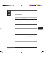
Contents
Preface ............................................................................................ v
Manual and Floppy Disks ................................................................. v
Operating Environments ................................................................. vi
Conventions .................................................................................... vi
Control Panel........................................................................... vii
Chapter 1
Getting Started ........................................................................... 1–1
Getting Acquainted ..................................................................... 1–1
Getting Ready ............................................................................. 1–4
Picking a Suitable Location ................................................... 1–4
Unpacking and Checking Your Printer ................................. 1–5
Setting Up ................................................................................... 1–7
Preparing the Print Unit and Installing the Toner Bottle ...... 1–7
Installing the Cleaner and Cleaner Pad ............................... 1–10
Loading Paper and Installing the Paper Tray ....................... 1–12
Installing the Multi-function Feeder ................................... 1–15
Connecting the Power Cord ............................................... 1–16
Connecting the Printer to Your Computer ................................ 1–17
About Interfacing ................................................................ 1–17
Connecting to the Parallel Port ........................................... 1–18
Printing a Test Page Offline ................................................ 1–19
Selecting an Emulation .............................................................. 1–20
Installing the Printer Driver ....................................................... 1–21
Get to Know Your Printer Driver ....................................... 1–21
Standard Printer Driver for Windows 3.1/3.11 ................... 1–22
FPS Printer Driver for Windows 3.1/3.11........................... 1–22
Standard Printer Driver for Windows 95 ............................ 1–22
Plug and Play Printer Detection ................................... 1–23
Set-up from "Printers" Folder ....................................... 1–23
FPS Printer Driver for Windows 95 .................................... 1–24
Printing Your First Document ................................................... 1–26
Adjusting Print Density ...................................................... 1–27
If Something Goes Wrong .................................................. 1–28
Where To Go From Here .......................................................... 1–29
User’s Manual
02 Contents
i
1
07.08.1997, 11:39 Uhr
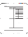
Contents
Chapter 2
Using Printer Software ...............................................................
Remote Setup Utility Program, PPMENU ..................................
Installing PPMENU .............................................................
Factory Defaults ....................................................................
Printer Management Utility Program, Lexmark’s MarkVision .....
Installing MarkVision ...........................................................
Menu Bar Functions .............................................................
Chapter 3
Printing and Paper Handling ...................................................... 3–1
Control Panel Tutorial ................................................................ 3–1
The Control Panel ................................................................ 3–1
Indicators ....................................................................... 3–2
Message Display ............................................................. 3–3
Buttons........................................................................... 3–3
Control Panel Functions .............................................................. 3–5
Changing Message Language ................................................. 3–5
Printing Data Remaining in the Buffer ................................. 3–5
Clearing an Error Condition to Continue Printing ............... 3–5
Clearing the Buffer and Reinitializing the Printer.................. 3–6
Printing a Status Report ........................................................ 3–6
Printing a Font Report .......................................................... 3–8
Selecting Paper Tray, MFF, or Manual Paper Feed ............. 3–10
Setting MFF Paper Size ....................................................... 3–11
Selecting Menu Option and Resetting Menu ...................... 3–12
Menu Functions ........................................................................ 3–12
Menu Structure and How to Use Control Panel Buttons .... 3–12
Submenus, Items, and Options ........................................... 3–13
Menu Items ............................................................................... 3–16
Handling Paper ......................................................................... 3–20
Paper Types and Sizes ......................................................... 3–20
General Tips ................................................................. 3–22
Preprinted Sheets .......................................................... 3–23
Transparencies .............................................................. 3–23
Envelopes ..................................................................... 3–24
Labels ........................................................................... 3–25
Changing the Paper Tray Size ............................................. 3–25
Using the Multi-function Feeder ......................................... 3–27
Feeding Paper Manually ...................................................... 3–29
Setting Up the Rear Stacker ................................................ 3–30
Printing on Nonstandard Size Paper and on Envelopes ....... 3–31
Considerations on Paper Size ........................................ 3–31
Page Orientation .......................................................... 3–32
ii
02 Contents
2–1
2–1
2–2
2–4
2–6
2–6
2–7
User’s Manual
2
07.08.1997, 11:39 Uhr
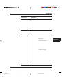
Contents
Chapter 4
Enhancing and Customizing the Printer ..................................... 4–1
Adding RAM ............................................................................... 4–1
Installing an Interface Expansion Board ....................................... 4–4
Installing an Interface Board ................................................. 4–4
Connecting to the Serial Port ................................................ 4–5
Connecting the Serial Interface Cable ............................. 4–5
Selecting the Serial Interface ........................................... 4–6
Verifying Serial Parameter Settings ................................. 4–6
Connecting to the LocalTalk Port ......................................... 4–7
Connecting the LocalTalk Interface Cable ...................... 4–8
Selecting the LocalTalk Interface .................................... 4–8
LocalTalk Specifications ................................................. 4–8
Connecting to the Ethernet Port ........................................... 4–9
Connecting the Ethernet Interface Cable ........................ 4–9
Selecting the Ethernet Interface .................................... 4–10
Ethernet Specifications ................................................. 4–10
Adding Paper Sources ................................................................ 4–10
Paper Feeder ....................................................................... 4–10
Changing the Paper Tray Size ............................................. 4–12
Different Paper Tray Sizes ................................................... 4–15
Adding Duplex Unit .................................................................. 4–15
Chapter 5
Maintenance .............................................................................. 5–1
Preventive Maintenance ............................................................... 5–1
Periodic Routine Maintenance .................................................... 5–2
Replacing the Toner Bottle and Cleaner Pad ......................... 5–2
Replacing the Print Unit and Internal Cleaning .................... 5–7
Removing the Print Unit ................................................ 5–8
Cleaning the Paper Path ............................................... 5–10
Cleaning the Corona Wire ........................................... 5–10
Cleaning the Paper Guide before the Corona Wire....... 5–11
Installing the New Print Unit ....................................... 5–12
Resetting the Print Unit Counter ................................. 5–15
Cleaning the Precharger Wire ............................................. 5–17
Repacking the Printer ................................................................ 5–18
User’s Manual
02 Contents
iii
3
07.08.1997, 11:39 Uhr
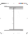
Contents
Chapter 6
Solving Problems ....................................................................... 6–1
Clearing Paper Jams .................................................................... 6–1
Operational Problems ................................................................ 6–10
Print Quality Problems .............................................................. 6–11
Error Indications ....................................................................... 6–13
Action-required Status Indications ............................................. 6–16
Printer Status Indications .......................................................... 6–17
Warning Messages ..................................................................... 6–18
Appendix A
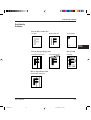
Font Samples .............................................................................. A–1
PCL Mode .................................................................................. A–1
FPS Mode ................................................................................... A–2
Appendix B
Supplies and Accessories .......................................................... B–1
Supplies ....................................................................................... B–1
Accessories ................................................................................... B–1
Appendix C
Specifications ............................................................................ C–1
Glossary ................................................................................... GL–1
Index ......................................................................................... IN–1
Fujitsu Offices......................................................... Inside back cover
iv
02 Contents
User’s Manual
4
07.08.1997, 11:39 Uhr
Preface
Thank you for purchasing the Fujitsu PrintPartner 14ADV Page Printer.
The PrintPartner 14ADV is a 14-ppm, 600-dpi, laser printer. It is
compatible with the HP LaserJet 4 printers or PostScript level 2 printers
which are main printers of the industry-standard page printers.
Available options are:
• 1-, 2-, 4-, 8-, 16-, and 32-megabyte memory expansion cards
• Interface expansion boards: serial interface, LocalTalk, and Ethernet C
• Paper trays (trays 1 and 2): A4, A5, letter, legal, and executive sizes
• Paper feeder: Base mechanism plus paper tray (tray 2)
• Duplex unit: Two-sided printing mechanism
Manual and
Floppy Disks
The PrintPartner 14ADV has a single user’s manual. This user’s manual
provides a summary of everything for from non-technical users unfamiliar
with page printers to highly experienced technical users.
The PrintPartner 14ADV comes with seven floppy disks.
• Windows Printer Drivers (two disks) which provide the computer’s
operating system with the programs that control this printer.
• MarkVision (three disks), printer management utility program,
which allows you to easily understand the printer (status, statistics,
or features) and displays the printer control panel on your
computer display to remotely operate the printer.
• Network Printer Utility (one disk), which allows you to remotely
change or confirm settings of Ethernet C board of the printer or
locally check the printer.
• PPMENU (one disk), the printer remote setup utility program,
which allows you to easily customize and program your printer to
your computer and software environments, using your computer
keyboard and display.
User’s Manual
03 Preface
v
5
07.08.1997, 11:39 Uhr
Operating Environments
Operating
Environments
To run the Printer Driver, you need an IBM PC/AT or PS/2
computer or compatible running MS-Windows 3.1/3.11 or MSWindows 95.
To run MarkVision, you need an IBM PC/AT or PS/2 computer or
compatible running MS-Windows 95 (not MS-Windows 3.1/3.11),
with at least 5MB of memory available on a hard disk, a 3.5" doublesided high density (2HD) floppy disk drive, and a VGA (640 × 480
dots) or higher resolution display.
To run the Network Printer Utility, you need an IBM PC/AT or PS/
2 computer or compatible running MS-Windows 3.1/3.11 (not MSWindows 95), with at least 5MB of memory available on a hard disk,
a 3.5" double-sided high density (2HD) floppy disk drive, and a
VGA (640 × 480 dots) or higher resolution display.
To run PPMENU, you need an IBM PC/AT or PS/2 computer or
compatible running MS-DOS, with at least 1MB of memory
available on a hard disk, a 3.5" double-sided high density (2HD)
floppy disk drive, and a VGA (640 × 480 dots) display. You must
also be using PC-DOS version 5.02, MS-DOS version 3.3, or higher
version.
Conventions
!
Caution:
☞
Icons draw your attention to advisory messages, as illustrated below.
A line precedes and follows the message to show where the message
begins and ends.
Notice:
✍
Important:
Ignoring this information could result in personal injury.
Ignoring this information could result in loss of data or harm to your
equipment.
These notes contain remarks, tips, and other useful supplementary
information.
vi
03 Preface
User’s Manual
6
07.08.1997, 11:39 Uhr
Operating Environments
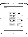
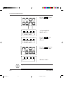
Control Panel
The printer’s control panel incorporates two rows of buttons, with each
button having one or two labels (see below). The physical button is
beneath the rectangular section of no-labeled space. The top label
represents the basic function, which is activated by a touch of the
button. The bottom label represents the second function, which is
activated when you release the button after holding it down more than
five seconds.
READY
FORM
FEED
MENU
+
Basic functions
Physical buttons
RESET
MENU
CONT.
TRAY
SELECT
ENTER
Second functions
Basic functions
–
Physical buttons
RESET
MFF
PAPER SIZE
SELF
TEST
PRINT
FONT
Second functions
The control panel has a character display of 16 columns × 2 lines.
In text, the names of the control panel buttons appear as all capital
letters inside a box like
and control panel display messages
appear in a fixed-spacing font like READY. Button names or messages
occupying two lines are expressed in a single line shown below.
Buttons:
FORM
FEED
Display messages: READY
TONER LOW
FORM FEED
READY
TONER LOW
The asterisk in the display column indicates that the displayed
option is currently selected in the selected menu.
User’s Manual
03 Preface
vii
7
07.08.1997, 11:39 Uhr
Operating Environments
Changing Message Language (
)
You can select a language used for control panel messages. Selectable
languages are English, French, German, Italian, Spanish, and Swedish.
To select a language, follow these steps:
.
1. Turning the printer on while pressing
The message C.P.LANGUAGE ENGLISH appears after printer
initialization.
2. Press the or button until the desired language appears. Press
the
button.
The asterisk appears after the language, indicating the language is
selected.
3. Save the selection.
Pressing the
button saves the new setting and returns the
printer to the ready state. The printer will display the selected
language for messages.
viii
03 Preface
User’s Manual
8
07.08.1997, 11:39 Uhr
CHAPTER
1
GETTING
STARTED
Getting Started
This chapter provides complete setup instructions in the following
sections:
•Getting Acquainted. Learning the printer’s main parts and its paper
paths.
•Getting Ready. Choosing a suitable location and unpacking the printer.
•Setting Up. Assembling the printer.
•Connecting the Printer. Selecting an interface and connecting to the
computer.
•Installing the Printer Driver.
•Printing Your First Document.
•Where to Go from Here.
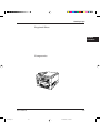
Getting
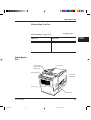
Acquainted
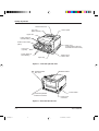
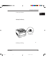
The illustrations on the following pages identify the main parts of the
printer and two routes of paper feeding. These parts are referred to
throughout the manual, so take some time to become familiar with
them.
User’s Manual
04 Chapter 1
1-1
1
07.08.1997, 11:39 Uhr
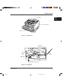
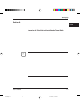
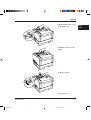
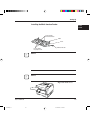
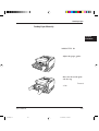
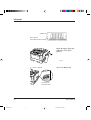
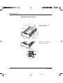
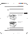
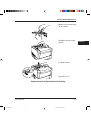
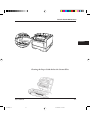
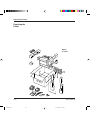
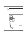
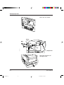
Getting Acquainted
Stacker-full sensor
Top cover
(Paper stacker)
Control panel
Upper door
Paper guides for
manual feeding
Multi-function feeder
(MFF)
Slide cover
(Font/emulation card slot
and RAM card slots inside)
Front cover
(opened)
Paper guides for
stack feeding
Multi-function
feeder cable
Paper tray
Figure 1–1 Front and right side view
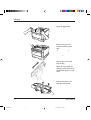
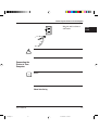
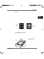
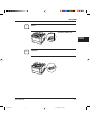
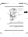
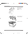
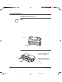
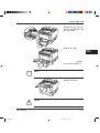
Interface board
slot cover
Rear stacker
Power switch
Centronics parallel
interface connector
Power cord
connector
Figure 1–2 Rear and left side view
1-2
04 Chapter 1
User’s Manual
2
07.08.1997, 11:39 Uhr
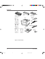
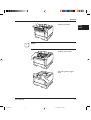
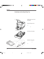
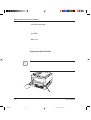
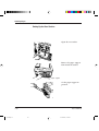
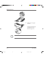
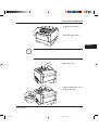
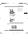
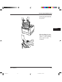
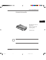
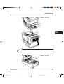
Getting Acquainted
Toner bottle
GETTING
STARTED
Print density dial
Print unit
Figure 1–3 Interior view
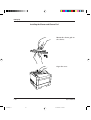
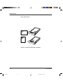
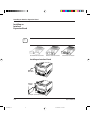
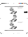
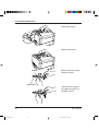
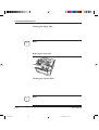
The path from the paper tray to the top cover is for ordinary paper.
The straight path from the manual feed slot or optional multifunction feeder to the rear stacker is for transparencies and envelopes.
Top cover
(main stacker)
Manual
feed
slot
Rear
stacker
Paper tray
From optional paper tray
Figure 1–4 Paper paths
User’s Manual
04 Chapter 1
1-3
3
07.08.1997, 11:39 Uhr
Getting Ready
Getting Ready
This section will help you:
• Choose a suitable location for the printer
• Inventory the parts of the printer as you unpack it
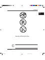
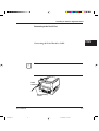
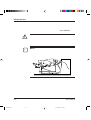
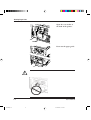
Picking a Suitable Location
The first step is to pick a suitable location for your printer. For peak
performance and usability, follow these guidelines:
• Place the printer on a
sturdy, level surface.
• Choose a room that is well
ventilated and free of
excessive dust. Leave space
on either side of the printer
for proper ventilation.
below
above
+10
+35
°C
°C
• To avoid exposing the
printer to extremes of
temperature, do not put the
printer in direct sunlight or
near a heater. Ideal room
temperature is from 10°C
to 35°C (50°F to 95°F).
Humidity should be
between 20% and 80% RH
(no condensation).
• Use a grounded AC power
outlet. Do not use a threepronged adapter in an
ungrounded outlet.
1-4
04 Chapter 1
User’s Manual
4
07.08.1997, 11:39 Uhr
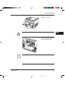
Getting Ready
• Use only the power cord
furnished with the printer.
Do not use an extension
cord.
• Do not touch any
connector contacts and
corona wires to avoid
possible electrostatic
damage to the printer.
• Do not use a circuit shared
with equipment that causes
electrical noise, such as
motors.
• Do not use a circuit shared
with equipment that uses a
lot of power, such as a
copier or a coffee maker.
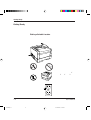
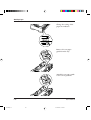
Unpacking and Checking Your Printer
As you unpack the printer, check each item carefully for damage. If
you find damage, notify your dealer. Check also that you have
received all the items shown below.
This printer comes with everything you need except an interface
cable. If you do not yet have a cable, you must purchase one before
you can connect the printer to your computer.
✍
Important:
Save the original carton and packing materials in case you need to
store or transport your printer.
User’s Manual
04 Chapter 1
1-5
5
07.08.1997, 11:39 Uhr
GETTING
STARTED
Getting Ready
Print unit
(placed in printer)
Toner
bottle
Printer driver
disks
Printer
Multi-function
feeder (MFF)
Paper size
label
Power
cord
MarkVision disks
Cleaner and
cleaner pad
Network printer
PPMENU disk
utility disk
User’s
manual
Cleaning
brush
• An interface cable is not a standard accessory. Please purchase
an appropriate cable according to the interface you intend to
use.
• The power cord may differ slightly from this figure depending
on the country where you purchased the printer.
• The multi-function feeder (MFF) is separately packaged.
Figure 1-5 Printer inventory
1-6
04 Chapter 1
User’s Manual
6
07.08.1997, 11:39 Uhr
Setting Up
This section describes how to assemble the printer and connect the
power cord after choosing a suitable location for the printer and
checking that you received all the parts.
Setting Up
Preparing the Print Unit and Installing the Toner Bottle
This printer is shipped with the print unit mounted and protective
materials attached. Be sure to remove the two protective materials
from the print unit. This operation is possible with the print unit
mounted. First prepare and install the following two components:
• Print unit (photoconductor drum, developing unit, etc.)
• Toner bottle
☞
The toner bottle first installed after you purchase the printer will last
about 2500 printed pages under the condition of 5% coverage on A4
paper. The succeeding toner bottles last about 5000 printed pages
each.
Notice:
Do not touch any connector contacts and corona wires to avoid
possible electrostatic damage to the printer.
Be careful with the print unit’s drum (the green surface). The drum
is easily damaged by contamination or by exposure to light for more
than three minutes. Follow these guidelines:
• Never touch or scratch the drum surface.
• When the print unit is not in the printer, store it in a dark place or
cover it with a clean sheet of paper.
• When the print unit is in the printer, keep the printer top cover
closed. If you must work inside the printer for more than three
minutes, remove the print unit with the toner bottle mounted and
store it in a dark place.
User’s Manual
04 Chapter 1
1-7
7
07.08.1997, 11:39 Uhr
GETTING
STARTED
Setting Up
To prepare the print unit and install the toner bottle, follow these steps:
1. Open the upper door. Lift
the milled portions at the
front left and right of the
upper door to open it.
e
w
2. Remove the protective
materials from the print
unit. Remove protective sheet
q. Pull clear tape w until its
blue end is visible and remove
it. Remove two restraint
cushions e.
q
3. Remove the toner bottle
from its bag.
4. Shake the toner bottle by
moving it back and forth in
a horizontal motion several
times.
5. Remove the plastic seal
from the toner bottle.
Gently pull off the seal being
careful not to spill toner.
Handle to seal carefully to
avoid staining your hands or
clothes.
Projecting guide
1-8
04 Chapter 1
User’s Manual
8
07.08.1997, 11:39 Uhr
Setting Up
☞
6. Install toner bottle. Slide
both projecting guides of the
toner bottle into the grooves
of the print unit.
Notice:
If you have installed the toner bottle, do not remove it from the print
unit until it is empty. This could causes toner to spill into the printer.
7. Lock the toner bottle. Push
the toner bottle forward until
it clicks into place. (The
bottle stands nearly upright
when installed correctly.)
8. Close the printer’s upper
door. Press down firmly on
the front portion of the upper
door and make sure the upper
door is locked completely.
User’s Manual
04 Chapter 1
1-9
9
07.08.1997, 11:39 Uhr
GETTING
STARTED
Setting Up
Installing the Cleaner and Cleaner Pad
This printer is shipped without installing the cleaner and cleaner pad
which removes dirt from the pressure roller in the fuser unit. Be sure
install the cleaner and cleaner pad before printing.
To install the cleaner and cleaner pad, follow these steps:
1. Mount the cleaner pad on
the cleaner. Put the cleaner
pad on the cleaner and slide
the cleaner pad into the
locked position.
2. Open the cover. Push the
engraved portion on the
stacker to unlock the cover.
1-10
04 Chapter 1
User’s Manual
10
07.08.1997, 11:39 Uhr
Setting Up
3. Lift the front of the cover
to open the cover.
4. Install the cleaner in the
printer. Grasp the handle
of the cleaner and put the
left end of the cleaner into
the opening, and then the
right end.
5. Lock the cleaner. Push
down the top of the handle
and pull it towards you to
lock the cleaner.
6. Close the cover.
User’s Manual
04 Chapter 1
1-11
11
07.08.1997, 11:39 Uhr
GETTING
STARTED
Setting Up
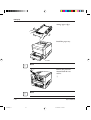
Loading Paper and Installing the Paper Tray
This printer has a single paper tray that is preset for letter size (8.5 x 11.0
inches) paper for U.S. customers and to A4 size (210 x 297 mm) paper
for European customers. (You can adjust the paper tray to a different size
paper. See Chapter 3. You can purchase an optional paper tray. See
Chapter 4 and Appendix B.) You should load about 50 sheets of copier
paper to test the printer.
q
*
1. Pull the paper tray out of
the printer.
2. Prepare the paper tray.
Remove restraint card board
q and tapes securing the rear
paper guide. Check green
indicator w is positioned
according to the tray size
label (*).
w
3. Lock the pressure plate. If
the front of the pressure plate
is raised, push it down until
the pressure plate clicks into
place.
4. Widen the side guides.
While bending both side
guides inward q, push their
inner PUSH marks outward
w.
1-12
04 Chapter 1
User’s Manual
12
07.08.1997, 11:39 Uhr
Setting Up
☞
5. Prepare a paper stack.
Prepare paper of the size
indicated by the size label (*).
Fan the paper stack both ways
to prevent sheets from
sticking together.
Notice:
Put the paper stack in the paper tray with the printing side faced down.
If paper is curled, remove the curl.
Limit mark
6. Load the paper. Place the
front portion of the paper
stack on the tray and slide it
backwards so that the stack is
placed under the two
stoppers. Gather the edges of
the stack together to ensure
correct positioning of paper
in the tray.
Make sure the stack does not
exceed the limit mark.
7. Adjust the side guides. Push
the outer PUSH mark of
either side guide to the width
of paper. Align the rear edges
of the paper stack.
Bad placement
Good placement
User’s Manual
04 Chapter 1
1-13
13
07.08.1997, 11:39 Uhr
GETTING
STARTED
Setting Up
8. Arrange paper edges. Rock
the paper tray to gather the
edges of the stack together to
ensure correct positioning of
paper in the tray.
9. Install the paper tray. Align
the sides of the tray with the
guide grooves of the tray slot
(the left groove is engraved
with a arrow) and firmly slide
the tray all the way into the
slot.
☞
Guide
Notice:
You cannot install the paper tray with the pressure plate raised.
☞
q
10.Remove the protective
material from the rear
stacker. Open the rear stacker
and remove restraint cushion
q. Make sure the paper
guide is pushed down in the
locked position. Close the
rear stacker.
Notice:
If the paper guide is not in the locked position, the printer will not work.
1-14
04 Chapter 1
User’s Manual
14
07.08.1997, 11:39 Uhr
Setting Up
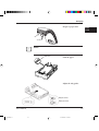
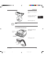
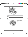
Installing the Multi-function Feeder
The multi-function feeder (MFF) is useful to print a lot of envelopes
or transparencies. The MFF can hold and deliver 100 sheets of 0.09
mm thick paper or 30 envelopes. Note that the printer works if the
MFF is not installed.
Paper guides
for manual feed
Hook
Lever
☞
Paper guides
for paper stack
MFF connector
Notice:
When using paper, do not leave the paper in the multi-function
feeder for long time. It may cause waving of paper and dropouts in
printing.
Because the MFF does not have a mechanism that detects the
physical size of paper in use, you must inform the printer of the
paper size. Use the MFF paper size menu to select a paper size which
equals the size of paper loaded in the MFF.
☞
To install the multi-function feeder, follow these steps:
Notice:
Be sure that the printer is turned off before installing or removing
the multi-function feeder.
1. Open the front cover.
User’s Manual
04 Chapter 1
1-15
15
07.08.1997, 11:39 Uhr
GETTING
STARTED
Setting Up
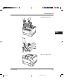
2. Fasten the feeder to the
printer. Insert the left and
right supports and hooks of
the multi-function feeder
into the corresponding
openings at the front of the
printer so that the hooks
catch the pins firmly.
☞
Arrow
mark
3. Connect the feeder cable.
Connect the feeder cable to
the connector at the right
side of the printer. Orient
the arrow mark of the
cable’s connector right.
Notice:
To avoid paper jams or other feeding errors, make sure that each of
the left and right hooks securely hangs on the pin.
Connecting the Power Cord
This printer comes equipped with one of the two voltage ratings:
• 120 VAC (such as for the USA)
• 220 to 240 VAC (such as for Europe)
The manufacturer’s nameplate on the back of the printer indicates this
rating. Confirm that the rated voltage of your printer matches the voltage
of your power outlet.
1. Check that the printer is
turned off. The “O”-marked
side of the switch should be
depressed.
2. Plug the female end of the
power cord into the
connector on the left back
of the printer.
1-16
04 Chapter 1
User’s Manual
16
07.08.1997, 11:39 Uhr
Connecting the Printer to Your Computer
3. Plug the male end into a
wall outlet.
!
☞
Connecting the
Printer to Your
Computer
Caution:
For your safety, use only a properly grounded outlet. To avoid possible
electromagnetic interference or power supply problems, do not use an
extension cord.
This section explains how to connect the printer to your computer via
the parallel interface. For information about the serial interface (option),
see Chapter 4.
Notice:
The following restrictions apply to interface cables:
• To comply with regulations for radio frequency emissions, use only
shielded cable for computer-to-printer communications.
• The length of the parallel interface cable must be 3 meters (10 feet) or
less.
About Interfacing
You can connect the printer to your computer using a standard parallel
interface. Many computers have a parallel interface port. However, if
your computer does not have the parallel interface port, or for printers
used in a network, the following optional interfaces are available.
User’s Manual
04 Chapter 1
1-17
17
07.08.1997, 11:39 Uhr
GETTING
STARTED
Connecting the Printer to Your Computer
• Serial (RS-232C/422A)
Use a serial interface if the printer is not near the computer. Many
computers have both parallel and serial interface ports. Serial
communication can operate up to 15 meters (50 feet). Parallel
communication is normally limited to 3 meters (10 feet).
• LocalTalk
Use the LocalTalk interface if the printer is connected to a Macintosh
network.
• Ethernet C
Use Ethernet C if the printer is used in a NetWare or UNIX
environment.
For any of these options refer to Chapter 3.
Connecting to the Parallel Port
☞
This printer does not come with a parallel interface cable. You can use a
standard Centronics interface cable (sold separately) for this purpose.
Your dealer can advise you on the cable you require.
Notice:
Be sure the printer is turned off before connecting the interface.
Do not touch any connector contacts or corona wires to avoid possible
electrostatic damage to the printer.
To make the connection, plug
the cable connector into the
parallel interface port on the
back of the printer. Secure the
connector with the wire clips.
Plug the other connector into
your computer’s parallel port.
Consult your computer
documentation if you need
help.
1-18
04 Chapter 1
User’s Manual
18
07.08.1997, 11:39 Uhr
Connecting the Printer to Your Computer
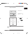
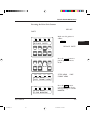
Printing a Test Page Offline
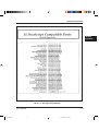
The printer has a status report function which prints a page
summarizing printer option settings and showing samples of resident
fonts. Use this function to check the printer performance offline.
POWER
ONLINE
DATA
ERROR
READY
READY
FORM
FEED
CONT.
TRAY
SELECT
ENTER
–
RESET
MFF
PAPER SIZE
SELF
TEST
PRINT
FONT
MENU
+
1. Turn the printer on. The
printer initializes the
mechanism and then enters
the ready state. The message
display indicates
<<<INITIALIZE>>>,
WARMING UP, then READY.
RESET
MENU
☞
2. Print a test page offline.
button to
Press the
put the printer offline (the
ONLINE indicator turns
off). Press the
button for more than five
seconds. The message
display indicates SELF
TEST and the DATA
indicator flashes. A status
report page is printed.
Check that the printing is
successful.
Notice:
The status report is for either the PCL emulation or the FPS emulation
depending on the emulation you used for printing the last document;
however, the status report is for the FPS emulation if it is printed
immediately after the printer is turned on. To clearly select the report,
use the test menu in setup mode.
User’s Manual
04 Chapter 1
1-19
19
07.08.1997, 11:39 Uhr
GETTING
STARTED
Selecting an Emulation
Selecting an
Emulation
This printer has two emulations (PCL and FPS) as a standard
feature. You can use these emulations to connect your printer to
different computers. PCL emulates HP LaserJet 4 printers and FPS
emulates PostScript Level 2 compatible printers.
With default settings, the printer automatically selects the active
emulation. To specify an emulation, select the emulation using the
control panel. Use the Personality menu of the Config menu as
shown below.
POWER
ONLINE
ERROR
DATA
READY
READY
FORM
FEED
CONT.
TRAY
SELECT
ENTER
–
RESET
MFF
PAPER SIZE
SELF
TEST
PRINT
FONT
ONLINE
DATA
MENU
+
RESET
MENU
POWER
ERROR
SETUP MENU
CONFIG MENU
POWER
ONLINE
ERROR
DATA
PERSONALITY
AUTO*
1. Enter setup mode. Press
the
button to put
the printer offline (the
ONLINE indicator turns
off). Then, press the
button briefly six times.
The message display
indicates SETUP MENU
CONFIG MENU.
2. Select the Personality
menu. Press the
button briefly. The message
display indicates
PERSONALITY AUTO*.
3. Select emulation. Press the
button briefly. The
option AUTO changes to
PCL, PS, then back to
AUTO. Press the
button when the desired
option is displayed.
The selected emulation is selected (an asterisk is followed). Once you
change the emulation, the other menus automatically change to
reflect the options and functions of the new emulation. For details of
the setup menu, see Chapter 3.
1-20
04 Chapter 1
User’s Manual
20
07.08.1997, 11:39 Uhr
Installing the Printer Driver
Installing the
Printer Driver
Now that you connected your printer to the parallel port of the
computer, you are ready to install the Windows Printer Driver which
controls the printer. There are two printer driver disks which contain
Standard Driver for Windows 3.1/3.11, Standard Driver for
Windows 95, and FPS Driver for Windows 95. Note that the
installation procedure differs.
When you are using Windows 95, it is recommended that you
should install the printer driver using MarkVision because the
printer driver is reinforced with MarkVision’s features such as
remotely changing settings of a network printer and checking status
of a network printer. For MarkVision, see Chapter 2.
To install a printer driver in Windows 95, note the following:
• When you install the printer driver, the original OS (CD-ROM or
floppy disks) is required during installation.
• When MarkVision may be already installed, select a printer name
followed by (MV) in the Printers window. When MarkVision is
not installed, select a printer name not followed by (MV).
Get to Know Your Printer Driver
The Printer Driver has two functions:
1. it automatically translates formatting choices, such as tab settings or
boldface type, into commands the printer understands.
2. it allows you to set up the printer according to your needs (printer
settings).
If you encounter problems with this installation, confirm that your
configuration corresponds to the minimum requirements listed on page
vi at the start of this manual. If the configuration corresponds to these
requirements and troubles persist, contact your dealer for assistance.
When running application programs under Windows, you select the
printer type in the application program itself before you print a
document.
User’s Manual
04 Chapter 1
1-21
21
07.08.1997, 11:39 Uhr
GETTING
STARTED
☞
Installing the Printer Driver
Notice:
If you encounter conflicts with other already installed external drivers
that use bidirectional communication on the Centronics port or with
drivers of other dedicated Windows printers used in parallel with this
printer (conflicts like the failure to establish communication between the
Printer Driver and the printer), remove these from Windows and
reinstall the PrintPartner 14ADV Printer Driver.
Standard Printer Driver for Windows 3.1/3.11
To install the Windows 3.1/3.11 Printer Standard Driver, follow these
steps:
1. Start Windows.
2. Insert the PrintPartner 14ADV Printer Driver disk into the 3.5 inch
floppy disk drive of your computer.
3. From the Windows Program Manager, select the "File" menu and
choose the "Run" command.
4. Type “A:\inst_xxx” or “B:\inst_xxx” and press the "Enter" key.
FPS Printer Driver for Windows 3.1/3.11
This printer driver is not contained in the attached floppy disks. Select a
printer driver corresponding to LaserWriter II NTX.
Standard Printer Driver for Windows 95
The Windows printer driver can be installed by either of the following
two methods. The first one applies when Windows 95 is started with the
printer ready and the second one applies when the printer is on after
Windows 95 has been started.
1-22
04 Chapter 1
User’s Manual
22
07.08.1997, 11:39 Uhr
Installing the Printer Driver
Plug and Play Printer Detection
1. Windows 95 automatically detects the printer at installation time or
during the boot process.
2. Plug and Play detection code will prompt the user for the appropriate
files, if they are not already resident in the Windows directory, by
displaying the “New Hardware Found” dialog box.
3. From the “New Hardware Found” dialog box, select “Driver from
disk provided by hardware manufacturer” and click “OK”.
4. The “Install from disk” dialog box will be displayed and you will be
prompted to select the drive and directory containing the installation
disk.
5. Insert the Printer driver installation disk into the A: or B: drive. Type
“A:\” or “B:\” and click “OK”.
6. The “Select Device” dialog box appears displaying the model-name
“Fujitsu PrintPartner 14ADV”. Click “OK” to continue.
7. Follow steps 8 to 11.
Set-up from "Printers" Folder
1. Click the "Start" button, point to "Settings", and then click "Printers".
2. Double-click "Add Printer".
3. The "Add Printer Wizard" will appear. Click “Next>”.
4. Click “Have Disk” from the next dialog box. The “Install from disk”
dialog box will be displayed and you will be prompted to select the
drive and directory containing the installation disk.
5. Insert the Printer driver installation disk into the A: or B: drive. Type
“A:\” or “B:\” and click “OK”.
6. A dialog box will display the model-names. Select “Fujitsu
PrintPartner 14ADV” and click “Next>” to continue.
7. A list of available Ports appears. Select an appropriate Port and click
“Next>”.
User’s Manual
04 Chapter 1
1-23
23
07.08.1997, 11:39 Uhr
GETTING
STARTED
Installing the Printer Driver
8. You will be prompted to type the Printer name. Type an appropriate
name or use the one supplied and click “Next>”.
9. The next dialog will prompt you to print a test page. Select “Yes” or
“No” and click “Finish”.
10.Driver files should now be automatically copied from the installation
disk.
11.When all files have been copied and the driver is installed, a dialog will
appear querying the result of test page printout. Depending on
whether the test page was printed correctly or not click “Yes” or “No”.
The Fujitsu PrintPartner 14ADV Windows 95 Standard Printer Driver is
now installed.
For further details, see the appropriate country version of the driver’s
Readme file.
FPS Printer Driver for Windows® 95
1. Start Windows.
2. Click the Start button, point to Settings, and then click Printers.
The Printers appears.
3. Double-click Add Printer. The Add Printer Wizard appears.
Click “Next>”.
4. Select “Local printer” or “Netwark printer”.
5. Printer manufacturers and names are listed. Click “Have Disk...”.
The “Install from disk” dialog is displayed.
6. Insert the Printer Driver disk into the A: drive and click the
“OK”. After the floppy disk files are copied, the dialog box
displays the model-name “Fujitsu CA0404x FPS2”.
7. Select “Fujitsu CA0404x FPS2” and click “Next>”. A list of
available Ports appears.
8. Select an appropriate Port (usually “LPT1”) and click “Next>”.
1-24
04 Chapter 1
User’s Manual
24
07.08.1997, 11:39 Uhr
Installing the Printer Driver
9. A dialog appears prompting the user to type the Printer name.
Type an appropriate name or use the one supplied and click
“Next>”. The next dialog prompts the user to print a test page.
10.Select “Yes” or “No” and click “Finish”. The self test printing
should be done to check for correct connection and settings of the
printer.
11.When all files have been copied and the driver is installed, the
selected printer’s icon is added in the Printers (the screen used in
step 1).
The Fujitsu PrintPartner 14ADV Windows 95 FPS Printer Driver is
now installed.
☞
For further details, see the appropriate country version of the driver’s
Readme file.
Notice:
To avoid possible printer errors, perform the following settings.
• Change the parameter of “Data Compression” in the PostScript tab of
the FPS2 driver Properties window to “Medium” to avoid a PS error.
• Change the parameters of “Halftone” in the Graphics tab of the FPS2
driver Properties window to “Use Settings Below”, “80.0” (Frequency),
and “45.0” (Angle) to avoid too dark printingor less.
You can also install the driver from MarkVision.
1. Click “Add Printer” of the Printer Installation.
2. Printer manufacturers and names are listed. Click “Have Disk...”.
The “Install from disk” dialog is displayed.
3. Follow the procedures from step 6 in the preceding procedures.
User’s Manual
04 Chapter 1
1-25
25
07.08.1997, 11:39 Uhr
GETTING
STARTED
Printing Your First Document
Printing Your First
Document
Your printer should be set up and connected to your computer. This
section explains how to test your installation setup by printing a trial
document from an application program under Windows. To test the
printer alone, without your computer, you can use the status report
printing which does not require the use of a computer. See Printing a
Status Report in Chapter 3.
Turn on your printer and observe the initialization sequence. If no RAM
(extra memory) cards have been installed, the sequence lasts about one
minute, during which the following events occur:
• The printer conducts a number of self-checks.
• The main motor rotates to check mechanical functions and clean the
drum.
• The message display indicates READY, indicating the printer is ready for
printing.
The following procedures show you how to print your trial document.
To print a trial document, follow these steps:
1. Start Windows and a Windows application.
2. Open your trial document.
Select an existing or start a new document. Choose a small document
for the first trial.
3. Select PP14ADV as the document printer.
In most programs, you make the selection in a print menu. Consult
your program documentation for the exact procedure.
4. If desired, change the font(s) in the document to one of the fonts
offered by your application.
5. Check the printer.
Look in the main window of the Print Manager to make sure the
printer is activated.
1-26
04 Chapter 1
User’s Manual
26
07.08.1997, 11:39 Uhr
Printing Your First Document
6. Print your document.
Start the program. The default paper size is fixed to A4 (for Europe)
or Letter (for the USA). However, you can print a document on a
different size of paper using the manual feed slot which you can
choose in the Printer Driver’s main window.
Adjusting Print Density
If you feel that the printout is too light or too dark, adjust the print
density by turning the print density dial. It is located inside the top cover
above the control panel. Turning the dial clockwise darkens the print. A
counterclockwise adjustment lightens the print. After making the
adjustment, close the top cover, print your trial document again, and
check the results.
Darken Lighten
Print density dial
If you see a problem with the printed pages other than print density, see
Chapter 6 for possible causes and solutions.
If your document printed successfully, skip the next subsection If
Something Goes Wrong.
User’s Manual
04 Chapter 1
1-27
27
07.08.1997, 11:39 Uhr
GETTING
STARTED
Printing Your First Document
If Something Goes Wrong
This section briefly discusses the most common problems you might
encounter. For more complete troubleshooting information, see Chapter
6. Chapter 6 also describes all printer error and status indicators.
Problem
Remedy
No response by printer
Ensure that:
• The printer is turned on and online. The
ONLINE indicator should be lit.
• The cable from the computer to the printer
is properly connected at both ends.
• Your software program has sent the print
data to the printer. Many programs have a
printer control function that shows print
No printout; DATA
indicator on
The printer has received data from the
computer but has not printed the page. To
print the page, put the printer offline by
briefly then press
pressing
.
Unreadable printout
Possible causes and solutions are:
• A wrong printer driver is selected. Select
the PrintPartner 14ADV printer driver as
the document printer.
• The document contains unknown printer
commands. Remove any setup strings or
embedded commands, or print the
document with a Text only or ASCII text
print option.
1-28
04 Chapter 1
User’s Manual
28
07.08.1997, 11:39 Uhr
Where To Go From Here
Where To Go
From Here
To help you enhance or customize the printer, the user’s manual
contains the following additional information:
• To get information on how to use the control panel and on
handling various types of paper, see Chapter 3.
• To customize printer defaults, see Chapter 3.
• To install additional memory, see Chapter 4.
• To load additional fonts, see Chapter 4.
• To install an alternate emulation, see Chapter 4.
• To add an additional paper tray, see Chapter 4.
• To install an additional duplex unit, see Chapter 4.
User’s Manual
04 Chapter 1
GETTING
STARTED
1-29
29
07.08.1997, 11:39 Uhr
Where To Go From Here
1-30
04 Chapter 1
User’s Manual
30
07.08.1997, 11:39 Uhr
CHAPTER
2
Using Printer Software
PRINTER
SOFTWARE
This chapter provides information about the two kinds of printer
management software stored in the floppy disks supplied with this
printer. The topics are:
• PPMENU. Explains PPMENU which enables you to remotely
control or configure your printer’s features from your computer’s
screen.
• MarkVision. Explains MarkVision which monitors printer status
(status is displayed with text and graphics), displays optional
printer’s features, spools print data, and cooperates with printer
drivers. It also describes the printer control panel function by
which MarkVision allows you to remotely operate your printer
from the printer control panel displayed on your computer’s screen.
Note that PPMENU is available in Windows 3.1/3.11 or Windows
95 environments and MarkVision is available in Windows 95
environments.
Remote Setup
Utility Program,
PPMENU
Generally, the printer driver controls the printer. You can also
control the printer using the remote setup utility program called
PPMENU, stored in the floppy disk labelled “PPMENU” which is
packaged with this manual.
This section focuses on PPMENU, which allows you to easily change
your printer’s features directly from your computer. You use it to
configure your printer to suit the requirements of your computer,
software, and documents to be printed.
The parameters you can change using PPMENU affect page layout,
font, and printer control. If your software programs have printer
drivers, those printer drivers control the parameters for you.
Therefore, it may not be necessary to change the settings using
PPMENU.
For more details and the latest modifications, refer to the
“ReadMe.txt” file in the PPMENU disk.
User’s Manual
04 Chapter 2
2-1
1
07.08.1997, 11:39 Uhr
Remote Setup Utility Program, PPMENU
Installing PPMENU
PPMENU needs to be installed only if you will print from DOS or
DOS based applications.
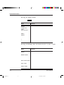
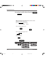
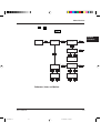
PPMENU first displays the opening screen then the main menu.
The main menu offers functions to select print options for your
documents. It also offers an operation guide of some keys and a help
message line. If the printer is not ready or has an error, a status
message is displayed. The top menu bar offers pull-down menus
about functions for setup data library, emulation and interface
setting, and maintenance. You can select options or perform a
function by using the main menu and top menu bar accessed
through your mouse or keyboard. One of the six languages (the
same one used in your user’s manual) is selectable for message display
when installing PPMENU.
To use PPMENU, your computer and its operating environments
must be as follows:
• IBM PC/AT or compatible or PS/2
• PC DOS 5.02, MS-DOS 3.3, or higher
• VGA (640 x 400) or higher display
• Hard disk drive installed (1 MB essential for PPMENU)
• 3.5-inch double-sided high density (2HD) floppy disk drive
(1.44 MB)
PPMENU is supplied with a 3.5 inch double-sided high density
(2HD) floppy disk (1.44 MB, 512 bytes/sector). Consult your
dealer when your computer does not have the corresponding floppy
disk drive.
To install PPMENU files and start PPMENU, follow these steps:
1. Insert the PPMENU disk in the floppy disk drive (suppose A).
2. Type A: then press ENTER.
3. Type \PPMENU2\INSTALL then press ENTER.
4. To run PPMENU, type PPMENU2 then press ENTER.
The following main menu is displayed if the printer has no error
after the opening screen is displayed.
2-2
04 Chapter 2
User’s Manual
2
07.08.1997, 11:40 Uhr
Remote Setup Utility Program, PPMENU
Library Special Options
Page Format
Copies
== Paper ============
Orientation
Formlines
Paper Source
Page Protect
Duplex Mode
Binding
Help
1
LETTER ===
PORTRAIT
60
TRAY 1
AUTO
OFF
LONG EDGE
Selectable options window)
LETTER
*
== A4 ==========
Executive
B5
COM10
DL
Font Settings
SEND
Print Quality
Smoothing (FEIT)
Resolution
Economy Mode
Thick Paper
ON
600
OFF
OFF
EXIT
(Operation guide window)
ALT+( ):
Enter:
TAB
:
ESC :
Cursor :
(Help window: describes item indicated by cursor)
Figure 2-1 PPMENU main menu (concept)
5. You can either use your keyboard or your mouse and left mouse
button to perform operations in the main menu. Follow these
steps if you will be using a keyboard:
• Select a pull-down menu: Alt key + L, S, or O key
• Select (highlight) a feature or option: TAB and cursor keys
• Confirm or execute: Enter key
• Cancel: ESC key
To apply new options to the printer, press the Tab key to select
the SEND button and press the Enter key. To save the settings,
select the "Save current settings" function from the top menu bar.
User’s Manual
04 Chapter 2
2-3
3
07.08.1997, 11:40 Uhr
PRINTER
SOFTWARE
Remote Setup Utility Program, PPMENU
6. To end PPMENU and exit to DOS or your application, choose
the item "Exit" in the "Library" menu or select the EXIT button
in the main menu. (PPMENU displays a message asking if the
options are to be saved.)
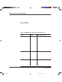
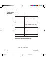
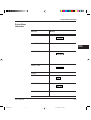
Factory Defaults
PPMENU initially shows the factory defaults of each item in the main
menu and the pull-down menus of the top menu bar. Table 2-1
shows the factory defaults and other options. The first three blocks
are for the main menu when the PCL emulation is selected as printer
personality and the others are for the pull-down menus.
Table 2-1 PPMENU factory defaults when emulation is PCL
Feature
Default
Other options or range
Copies
Paper
Orientation
Form lines
Paper source
1
Letter (*1)
Portrait
60 (*2)
Tray 1
Page protect
Duplex mode (*4)
Binding (*4)
Auto
Off
Long edge
1 to 99 pages
A4, A5, Legal, Executive, etc.
Landscape
5 to 128 lines
Manual feed, Tray 2, MFF,
AUTO (Tray 1 not used),
AUTO (Tray 2 not used),
AUTO (MFF not used),
AUTO (All Select) (*3)
On
On
Short edge
Typeface name
Font source (*5)
Pitch
Point size
Symbol set (*6)
Compatible mode
Courier
Internal
10.00
12.00
Roman8
On
CG Times, Univers, and so on
Soft font, SIMM font
0.44 to 99.99 cpi
4.00 to 999.75 point
PC-8, ISO6, ISO11, and so on
Off
Smoothing (FEIT)
(*7)
Resolution
Economy mode
Thick paper
1200 dpi class
On
600
Off
Off
Off (Resolution is 600 dpi)
Off (Resolution is 300 dpi)
300 dpi
On
On
2-4
04 Chapter 2
User’s Manual
4
07.08.1997, 11:40 Uhr
Remote Setup Utility Program, PPMENU
Feature
Default
Other options or range
Personality (*8)
Auto
PCL, PS
Jam recovery (*9)
PS error report (*9)
Off
Off
On
On
Auto continue
Off
On
Acknowledge (*10)
I/O timeout (*11)
Inside
15
Outside
15 to 300 seconds
Parallel interface
Serial interface
LPT1
COM1
LPT2, LPT3
COM2
Top offset (*12)
0.0
Left offset (*12)
0.0
-25.0 to +25.0 mm
(0.1 mm steps)
-25.0 to +25.0 mm
(0.1 mm steps)
PRINTER
SOFTWARE
*1 Letter for USA and A4 for Europe
*2 This is for letter and portrait. It automatically changes depending on
paper size and page orientation.
*3 Tray 2 is displayed when the optional paper feeder is installed. MFF
is displayed when the optional multi-function feeder (MFF) is
installed. AUTO (Tray 1 not used), AUTO (Tray 2 not used),
AUTO (MFF not used), and AUTO (All Select) are displayed
collectively as AUTO when above options are not installed.
*4 Duplex mode and binding are valid when the duplex unit is installed.
*5 Font source is subordinate to the typeface and cannot be selected.
*6 The screen format changes depending on font information (except
for resident fonts) and compatible mode setting.
*7 FEIT is the acronym for Fujitsu Enhanced Image Technology that
makes the contours of objects appear smoother than with this
printer’s resolution normally possible.
*8 The screen format changes depending on personality setting.
*9 Jam recovery and PS error report are valid when the optional FPS
card (PostScript level 2 compatible emulation card) is installed.
*10 This is for the Centronics parallel interface.
*11 This is essential for sharing the printer among multiple computers.
*12 Effective when PCL is selected for the personality. These values are
used as defaults of top and left offset specifications in PCL mode.
User’s Manual
04 Chapter 2
2-5
5
07.08.1997, 11:40 Uhr
Printer Management Utility Program, MarkVision
Printer Management Utility
Program,
Lexmark’s
MarkVision
MarkVision by Lexmark is an integrated software for managing
printers, stored in the floppy disk labelled “MarkVision” which is
packaged with this manual. It has the following main functions:
• Monitoring the printer
• Displaying the printer status and features (including options) and
statistics
• Providing the printer control panel on the computer’s screen
(Remote control panel)
These functions are most effective and valuable for remote printers in
network environments.
MarkVision is automatically activated when an abnormal condition
occurs in the printer. It operates in Windows 95 environments only.
The remote control panel is quite a nice function that enables you to
easily and remotely operate the printer even if your printer is set up
remotely. MarkVision displays the printer control panel on the
computer’s screen and gives you the exactly same functions as
available with the control panel of the printer. You can perform a
function by clicking a button on the computer’s screen without
pushing a button of the printer’s control panel.
Installing MarkVision
To use MarkVision, your computer and its operating environments
must be as follows:
• IBM PC/AT or compatible or PS/2
• Microsoft Windows 95 (not Windows 3.1/3.11)
• VGA (640 x 400) or higher display
• Hard disk drive installed (5 MB essential for MarkVision)
• 3.5-inch double-sided high density (2HD) floppy disk drive
(1.44 MB)
MarkVision is supplied with three 3.5 inch double-sided high
density (2HD) floppy disks (1.44 MB, 512 bytes/sector). Consult
your dealer when your computer does not have the corresponding
floppy disk drive.
To install MarkVision files and start MarkVision, follow these steps:
2-6
04 Chapter 2
User’s Manual
6
07.08.1997, 11:40 Uhr
Printer Management Utility Program, MarkVision
1. Insert the Disk 1 of “MarkVision” disk in the floppy disk drive
(A or B drive).
2. On the Start menu, click Run.
PRINTER
SOFTWARE
3. Type A:SETUP, then press ENTER.
4. Follow the instructions on the screen. If you want to install the
printer driver, click the Custom box from the Printer Installation
dialog.
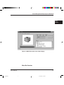
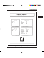
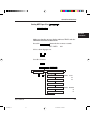
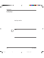
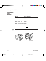
The following screen is displayed if the printer has no error.
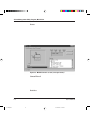
Figure 2-2 MarkVision main screen (status display)
The top menu bar offers three functions. The screen displays
information and a graphic of the printer corresponding to the
function selected. The bottom line displays printer status.
Help is available from each screen. Highlight the item you want to
know more about; then press the F1 key on your computer keyboard.
Press the ESC key on your keyboard to exit the online Help.
Menu Bar Functions
The three functions of the top menu bar are as follows:
User’s Manual
04 Chapter 2
2-7
7
07.08.1997, 11:40 Uhr
Printer Management Utility Program, MarkVision
Status:
Shows a printer status message which is identical to the message
appearing on the printer control panel. The status is also indicated
graphically. You can determine what the printer is doing and what
the printer needs to complete the task. It also includes information
about the printer’s features including options which are installed on
the printer.
With an optional setting, the MarkVision icon flashes to let you
know there is a problem with the printer even if the icon is
minimized on your monitor.
Figure 2-3 MarkVision main screen (cover open status)
Control Panel:
Allows you to remotely operate your printer. It displays an exact
replica of the physical control panel on the printer, on your monitor.
Click the appropriate button on the screen by the mouse as if you are
pressing the real button on the printer control panel by a finger.
Both panels have exactly the same functions.
Statistics:
Summarizes details about jobs such as the total number of jobs
printed, total pages, and average print time.
2-8
04 Chapter 2
User’s Manual
8
07.08.1997, 11:40 Uhr
CHAPTER
3
Printing and Paper Handling
This chapter provides information you may need for day-to-day
printing. The topics are:
• Control panel tutorial
The tutorial describes the indicators, message display, and buttons.
It includes an example of how to use the control panel.
• Control panel functions
This section describes the functions by buttons.
• Menu functions
This section describes how to use the control panel for customizing
printer defaults.
• Handling paper
This section describes how to print on various types of paper.
Control Panel
Tutorial
This section introduces the printer’s control panel, beginning with a
description of the indicators, message display, and buttons. The
tutorial describes the use of the buttons in some detail and follows
with an example.
The Control Panel
The control panel consists of four indicators, a message display, and
eight buttons. The physical buttons are beneath the LCD display.
The top row of labels represents basic functions. The bottom row of
labels represents secondary functions. See later in this section for a
list of functions.
User’s Manual
05 Chapter 3
3-1
1
07.08.1997, 11:40 Uhr
PRINTING AND
PAPER HANDLING
Control Panel Tutorial
POWER
READY
ONLINE
DATA
FORM
FEED
MENU
ERROR
+
RESET
MENU
CONT.
TRAY
SELECT
ENTER
–
RESET
MFF
PAPER SIZE
SELF
TEST
PRINT
FONT
Figure 3–1 Control panel
Indicators
The control panel has four labeled LED indicators across the top.
Indicator
Meaning
POWER
Indicates printer power is on.
ONLINE
Indicates the printer is online and ready to print.
DATA
Flashes when data is being sent from your computer.
Lights steadily to indicate the printer’s buffer contains
unprocessed data.
ERROR
Indicates a printer error has occurred. Details are
indicated by the message display.
3-2
05 Chapter 3
User’s Manual
2
07.08.1997, 11:40 Uhr
Control Panel Tutorial
Message Display (LCD)
The message display uses a liquid-crystal display representing status
and errors by two lines of sixteen characters. In operating mode, it
may show:
• What the printer is doing
• Whether the printer is ready to print
• When paper should be added
• When paper should be manually inserted
• When the toner bottle needs to be replaced
• When the print unit needs to be replaced
• An error message condition such as paper jam
✍
Important:
A "Ready" message means the printer has no data to print without
any errors and the
button is not pressed. "Not Ready"
means the printer detected an error or the
button was
pressed in the Ready state.
Error messages inform you of conditions requiring your attention,
such as TRAYn PAPER OUT, COVER OPEN n, or PAPER JAMn.
They also warn you of hardware problems, such as FUSER FAILURE
or BD CYCLE ERROR. The TONER LOW message informs you that
the toner bottle needs replacement. See Chapter 6 for a complete list
of messages and explanations.
In tray select mode or MFF paper size mode, the message display
shows the selected tray or the selected paper size respectively. In
menu mode, the message display shows menu items and option
selections. These modes are explained later in this chapter.
Buttons
One or two functions are assigned to a button. To use the functions
represented by the top labels, simply press the button. To use the
functions represented by the bottom labels, press and hold down the
button for five or more seconds. The following tables summarizes the
functions.
User’s Manual
05 Chapter 3
3-3
3
07.08.1997, 11:40 Uhr
PRINTING AND
PAPER HANDLING
Control Panel Tutorial
Pressing the button briefly
button, the following buttons are also valid when
Except for the
the printer is offline.
Button
Function
READY
FORM FEED
CONT.
TRAY SELECT
Switches the printer between online and offline.
Performs a form feed to print the remaining data.
Clears a recoverable error and continues printing.
Puts the printer in tray select mode which allows
you to select the paper tray to be used.
Puts the printer in setup mode.
Selects the displayed option as the printer default.
This button and the two buttons below are valid
in setup, tray select, or MFF paper size mode.
Displays the next option.
Displays the previous option.
MENU
ENTER
+
–
Pressing and holding down the button for five or more seconds
The following buttons are also valid when the printer is offline.
Button
Function
RESET
Clears the buffer of any print data and puts the
printer through its initialization sequence.
Besides the above reset function, resets all printer
operation options to their factory default values
except interface settings (parallel menu, serial
menu, and network menu).
Puts the printer in MFF paper size mode, which
allows you to select the paper size to be used.
Prints a status report, which lists printer
operation options currently selected.
Prints a font report, which lists the fonts
currently available.
RESET MENU
MFF PAPER SIZE
SELF TEST
PRINT FONT
3-4
05 Chapter 3
User’s Manual
4
07.08.1997, 11:40 Uhr
Control Panel Functions
Control Panel
Functions
Changing Message Language (
)
You can select a language used for control panel messages. Selectable
languages are English, French, German, Italian, Spanish, and Swedish.
To select a language, follow these steps:
1. Turning the printer on while pressing .
The message C.P.LANGUAGE ENGLISH appears after printer
initialization.
button until the desired language appears.
2. Press the or
Press the
button.
The asterisk appears after the language, indicating the language is
selected.
3. Save the selection.
Pressing the
button saves the new setting and returns the
printer to the ready state. The printer will display the selected
language for messages.
Printing Data Remaining in the Buffer (
)
Pressing
tells the printer to advance to the next page.
The practical effect is to print any data remaining in the buffer. For
example, the buffer might contain data from an interrupted print
job. When the buffer contains residual data, the control panel DATA
indicator is steadily lit.
Clearing an Error Condition to Continue Printing (
)
When a recoverable error occurred, pressing
clears the error
condition and continues printing. For example, you can resume
printing after adding paper in response to a TRAY1 PAPER OUT
message. You can use
to ignore a message such as Load
TRAY1 A4. For example, you might want to print a page with A4also allows you to override
size format on a letter-size sheet.
the INSERT A4 prompt when feeding paper manually. By pressing
, the printer prints from tray1 (MFF) instead.
User’s Manual
05 Chapter 3
3-5
5
07.08.1997, 11:40 Uhr
PRINTING AND
PAPER HANDLING
Control Panel Functions
Clearing the Buffer and Reinitializing the Printer (
)
Pressing and holding down
for five or more seconds clears the
print buffer and tells the printer to initialize itself. You might use
this function if you cancel a print job in the middle and want to clear
the printer and start over. In this case, permanently downloaded
fonts are removed by the initialization process. You must download
the fonts again.
Printing a Status Report (
)
The status report function prints a page that summarizes printer
option settings and shows samples of resident fonts.
To print a status report, follow these steps:
1. Make sure that the message display indicates
READY with the
ONLINE and DATA indicators off.
☞
2. Press the
button for five or more seconds.
The message changes to SELF TEST with the DATA indicator
flashing and the status report begins printing. After printing, the
printer returns to the original state. See Figure 3-2.
Notice:
The status report is for either the PCL emulation or the FPS
emulation depending on the emulation you used for printing the last
document; however, the status report is for the FPS emulation if it is
printed immediately after the printer is turned on. To clearly select
the report, use the test menu in setup mode. See Chapter 3.
3-6
05 Chapter 3
User’s Manual
6
07.08.1997, 11:40 Uhr
Control Panel Functions
PRINTING AND
PAPER HANDLING
Figure 3–2 Status report (FPS emulation)
User’s Manual
05 Chapter 3
3-7
7
07.08.1997, 11:40 Uhr
Control Panel Functions
Printing a Font Report (
)
The font report summarizes attribute information on resident and
optional fonts currently available and shows samples of these fonts.
To print a font report, follow these steps:
1. Make sure that the message display indicates
READY with the
ONLINE and DATA indicators off.
☞
2. Press the
button for five or more seconds.
The message changes to PRINT FONT with the DATA indicator
flashing, and the status report begins printing. After printing, the
printer returns to the original state. See Figure 3-3.
Notice:
The font report is for either the PCL emulation or the FPS
emulation depending on the emulation you used for printing the last
document; however, the font report is for the FPS emulation if it is
printed immediately after the printer is turned on. To clearly select
the report, use the test menu in setup mode. See Chapter 3.
3-8
05 Chapter 3
User’s Manual
8
07.08.1997, 11:40 Uhr
Control Panel Functions
PRINTING AND
PAPER HANDLING
Figure 3–3 Font report (FPS emulation)
User’s Manual
05 Chapter 3
3-9
9
07.08.1997, 11:40 Uhr
Control Panel Functions
Selecting Paper Tray, MFF, or Manual Paper Feed (
)
Pressing
puts the printer in tray select mode which allows
you to select paper sources to be used. The paper sources are tray 1, tray 2
(if installed), MFF (if installed), and manual feed slot. When a paper
source runs out of paper, the printer switches it for another one. When
the manual feed slot is selected, other paper sources are made invalid.
To select a paper source, follow these steps:
1. Make sure that the message display indicates READY with the
ONLINE and DATA indicators off.
button briefly.
2. Press the
The message changes to TRAY
TRAY1*. The asterisk means that
tray 1 is selected.
3. Select or deselect a paper source.
This step is valid when tray 2 (option) or MFF (standard) is installed.
Pressing the
button in this condition makes the asterisk
button again
disappear. Tray 1 is deselected. Pressing the
makes the asterisk reappear. Tray 1 is selected.
4. Select or deselect other paper sources.
Press the or buttons briefly to display another paper source. Use
the
button in the same way as described above.
5. Save the selections.
Press
ready state.
READY
or
button to save the new settings and return to the
TRAY
TRAY1*
MANUALFEED OFF*
TRAY
TRAY2
MANUALFEED
TRAY
MFF
3-10
05 Chapter 3
ON
User’s Manual
10
07.08.1997, 11:40 Uhr
Control Panel Functions
Setting MFF Paper Size (
)
Pressing
puts the printer in MFF paper size mode
which allows you to inform the controller of the physical paper size
used in the MFF. You must select the size of paper currently loaded
in the MFF. This menu is available when the MFF is installed.
To select a paper size, follow these steps:
1. Make sure that the message display indicates READY with the
ONLINE and DATA indicators off.
button for five or more seconds.
2. Press the
A4*. The asterisk
The message changes to MFF PAPER
means that A4 size is selected for the MFF.
3. Select a desired paper size.
Press the
Press the
is selected.
or
buttons until the desired paper size appears.
button. The asterisk appears and the paper size
4. Save the selection.
Press the
ready state.
button to save the new setting and return to the
(
READY
or
)
MFF PAPER
LETTER*
MFF PAPER
XXXXX
MFF PAPER
XXXXX: LEGAL
A4
A5
EXECUTIVE
MFF ENVELOPE
COM10
MFF ENVELOPE
XXXXX
XXXXX: MONARCH
C5
MFF ENVELOPE
B5
User’s Manual
05 Chapter 3
DL
3-11
11
07.08.1997, 11:40 Uhr
PRINTING AND
PAPER HANDLING
Menu Functions
Selecting Menu Option (
(
)
) and Resetting Menu
Pressing
briefly puts the printer in menu mode which allows
you to set up the printer, for example, selecting a paper size,
changing a font, and adjusting serial interface parameters. You can
select options from the menu by using the four buttons,
, ,
, and
.
for five or more seconds in menu mode resets
Pressing
all parameters to the factory default values except interface settings
(parallel menu, serial menu, and network menu).
The following section briefly explains the menu mode and its
operation.
Menu Functions
The menu mode allows you to change your printer’s defaults using
the four buttons on the control panel. You can use the control
panel's menu mode to configure your printer to suit the
requirements of your computer, software, and documents.
Menu Structure and How to Use Control Panel Buttons
The menu mode is structured as a tree consisting of submenus,
items, and options. The following example shows a small portion of
the tree and illustrates how the four buttons work. (Fig. 2-6)
In the example:
Submenus are PAGE FORMAT MENU and QUALITY MENU. Items
are COPIES, PAPER, and SMOOTHING. Options are 001, 002,
LETTER, LEGAL, ON, and OFF.
selects menu mode when the printer is ready and offline.
selects the first submenu
Once the printer is in menu mode,
and moves you right to the next submenu. If you are on the last
returns you to the first submenu.
submenu, pressing
selects the first item of the
When a submenu is selected,
submenu. Once the first item is selected,
moves you right to
the next item, regardless of an option selected. If you are on the last
item, pressing
returns you to the first item.
3-12
05 Chapter 3
User’s Manual
12
07.08.1997, 11:40 Uhr
Menu Functions
Use
and
to move up and down the options list.
When an item is displayed,
selects that option (adds an
asterisk after the option indicating that the option is stored in RAM).
PRINTING AND
PAPER HANDLING
READY
SETUP MENU
MENU
MENU
PAGE FORMAT MENU
SETUP MENU
MENU
QUALITY MENU
ENTER
SMOOTHING
ON*
ENTER
–
+
SMOOTHING
OFF
COPIES
001*
+
–
COPIES
002
+
–
PAPER
MENU
LETTER*
+
–
PAPER
LEGAL
+
–
MENU
MENU
Submenus, Items, and Options
The following table shows all of submenus and items and summary
of options displayed on the message display in menu mode. The
display initially shows the factory default option followed by an
asterisk (underlined in the table).
User’s Manual
05 Chapter 3
3-13
13
07.08.1997, 11:40 Uhr
Menu Functions
Submenu (bold)/Item Options
Page format menu
Copies
Paper/Envelope
Orientation
Form lines
Page protect
Duplex mode
Bind
001, 002, 003, ..., 999 (pages)
A4, A5, Letter, Legal, Executive (*1)
COM10, Monarch, C5, DL, B5
Portrait, Landscape
005, 006, 007, ..., 060, ..., 128 (lines/page) (*2)
Auto, On
Off, On (*3)
Long edge, Short edge (*3)
Quality menu
Smoothing (*4)
Resolution
Economy mode
Thick paper
On, Off
600, 300 (dpi)
Off, On
Off, On
PCL font menu
Font source
Font number
Pitch size (*6)
Point size (*7)
Symbol set
Compatible mode
Internal, Soft, SIMM (*5)
000, 001, 002, 003, ..., N (depending on the font
source, max. 999)
0.44, 0.45, 0.46, ..., 99.99 (characters/inch)
4.00, 4.25, 4.50, 4.75, 5.00, ..., 999.75 (point)
Roman8, ISOL1, ISOL2, ISOL3, PC8, PC8-DN,
PC850, PC852, PC8TK, ..., WingDings
On, Off
PCL menu (*8)
Top offset
Left offset
A4 print width
-25.0, -24.9, -24.8, ..., 00.0, ..., +24.9, +25.0 (mm)
-25.0, -24.9, -24.8, ..., 00.0, ..., +24.9, +25.0 (mm)
Normal, 80 columns/line
FPS menu (*9)
Jam recovery
Print FPS errors
Job timeout
Wait timeout
Manual timeout
Banding mode
Off, On
On, Off
0, 10, 11, 12, ..., 298, 299, 300 (0: no check)
0, 10, 11, 12, ..., 298, 299, 300 (0: no check)
0, 10, 11, 12, ..., 40, ..., 298, 299, 300 (0: no check)
Auto, Off, On (*10)
3-14
05 Chapter 3
User’s Manual
14
07.08.1997, 11:40 Uhr
Menu Functions
Submenu (bold)/Item Options
Config menu
Personality
Auto continue
I/O timeout (*11)
I/O buffers
NPAP area size
Power save
Auto, PCL, PS
Off, On
5, 6, 7, ..., 15, ..., 298, 299, 300 (seconds)
Auto, 4K, 16K, 32K, 64K (bytes)
Auto, Large, Medium., Small
Off, On after 15 min, On after 30 min, On after
60 min, On after 120 min
Parallel menu
Acknowledge (*12)
Bi-direction
NPAP mode
Inside, Outside
On, Off
Auto, On, Off
Serial menu (*13)
Baud rate
Format
Flow control
1200, 2400, 4800, 9600, 19200, 38400, 57600
8Non1, 7Even1, 7Odd1, 8Even1, 8Odd1
DTR Hi, DTR Low, XOn/Off, ROBUST XOn/Off
Network menu (*14)
NPAP mode
Bootp
IP address
IP netmask
IP gateway
Test menu
PCL config page
PCL font list
FPS config page
FPS font list
Clear warning
<Clear warning>
Auto, On
No, Yes
###. ###. ###. ### (### = 0, 1, 2, ..., 255) (*15)
###. ###. ###. ### (### = 0, 1, 2, ..., 255) (*15)
###. ###. ###. ### (### = 0, 1, 2, ..., 255) (*15)
No option. Pages are printed when an item is selected.
Start
Start
Start
Start
Shows the printing component to be replaced.
Print unit
*1 Letter for U.S. customers and A4 for European customers
*2 This is for Letter and portrait. It automatically changes depending
on paper size and page orientation.
*3 Valid when a duplex unit is installed
*4 Also called FEIT (Fujitsu Enhanced Image Technology) which
makes the contours of objects appear smoother than normally
possible with the printers standard resolution.
User’s Manual
05 Chapter 3
3-15
15
07.08.1997, 11:40 Uhr
PRINTING AND
PAPER HANDLING
Menu Items
*5 Displayed when soft fonts are downloaded or a font SIMM card is
installed
*6 Displayed when the selected font is a scalable and fixed-spacing one
*7 Displayed when the selected font is a scalable and proportionalspacing one
*8 Effective when PCL jobs are being executed. These values are used
as defaults of top and left offset specifications in PCL mode.
*9 Displayed when the FPS is selected for personality
*10 If the total capacity of memory is 3M to 9M bytes with banding
mode off, the resolution is automatically set to 300 dpi. When
intending to print at 600 dpi, select “banding mode on” or install
additional memory cards of 6M bytes or more.
*11 This is essential for sharing the printer among multiple computers.
*12 This is for the parallel interface.
*13 Displayed when a serial interface board is installed
*14 Displayed when a network interface board is installed
*15 Consists of four parameters. The one followed by < can be changed.
The following briefly explains each item of the menu mode.
Page format menu
Copies
Menu Items
Paper/Envelope
Orientation
Form lines
Page protect
Duplex mode
Binding
The number of copies the printer prints from
each page
A paper size or envelope size to be used by the
printer
A printing direction
The number of lines printed per page
Whether a block of printer memory is reserved
exclusively for text and graphics data,
especially for printing dense text or complex
graphics, to prevent memory overflow errors.
However, it reduces the amount of printer
memory available for downloadable fonts.
Two-sided printing mode
Where an extra area for fastening pages is
located, short or long edge of a page
3-16
05 Chapter 3
User’s Manual
16
07.08.1997, 11:40 Uhr
Menu Items
Quality menu
Smoothing
Resolution
Economy mode
Thick paper
PCL font menu
Font source
Font number
Pitch size
Point size
Symbol set
Compatible mode
PCL menu
Top offset
Left offset
A4 print width
Normal
80 columns/line
FPS menu
Jam recovery
Print FPS errors
Job timeout
Wait timeout
Whether the edge smoothness technology is
applied (improves resolution to 1200 dpi class)
The number of dots printed per inch
Toner saving mode
Mode for printing thick paper. Be sure to turn
this off whenever you are using paper of
ordinary thickness.
Where the printer finds the font
The internal number of a font to be selected
Character width (characters per inch)
Character height (multiple of 1/72 inch)
A set of characters used in a font, consisting of
the standard letters, numbers, and punctuation.
It differs in the accented characters, line drawing
characters, and special symbols by languages.
PCL5e compatible font mode
Distance by which the page is virtually shifted
from the top edge of physical paper in PCL
emulation
Distance by which the page is virtually shifted
from the left edge of physical paper in PCL
emulation
Setting the width of the printable area for A4
paper size
PCL5e compatible
Expands the width of the printable area so that
80 characters of a 10-pitch font can be printed
within a line. This setting is available only for
A4 paper size in portrait orientation.
Whether the jammed page is reprinted
Whether an error report is printed out
Time interval to be allotted between jobs
Time interval to be allotted for waiting a job end
User’s Manual
05 Chapter 3
3-17
17
07.08.1997, 11:40 Uhr
PRINTING AND
PAPER HANDLING
Menu Items
Manual timeout
Banding mode
Auto
Off
On
Config menu
Personality
Auto continue
I/O timeout
I/O buffers
NPAP area size
Power save
On after 15 min
On after 30 min
On after 60 min
On after 120 min
Off
Time interval to be allotted for manual insertion
Switching printing control (band/full page)
Auto mode (standard setting). Switches the
following two modes depending on the total
RAM capacity: virtual memory mode for
10MB or less (equivalent to banding mode on)
and speed mode for more than 10MB
(equivalent to banding mode off)
Speed mode. Attaches importance to speedup
of printing control, thus processing all pages
per job. Print density is set to 300 dpi when
total RAM capacity is 3M to 9M bytes. To
print on legal-size paper, set banding mode on,
or the total RAM capacity must be 10M bytes
or more.
(Virtual) memory mode. Attaches importance
to reliable printing rather than speedup, thus
processing data per page.
Selecting an emulation (personality) without a
PJL command which clearly specifies the
emulation
Automatic control of continuing recoverable
errors
Time interval allowed for switching the
interface
Size of interface buffer
Size of work area for NPAP (network printer
alliance protocol)
Setting the time interval during which the
printer remains idle state before sleep mode
after printing last
Power save mode on. The printer enters sleep
mode after remaining idle state for ## minutes
after printing last.
Power save mode off. (Even in this mode, the
printer enters sleep mode after remaining idle
state for 180 minutes.)
3-18
05 Chapter 3
User’s Manual
18
07.08.1997, 11:40 Uhr
Menu Items
Parallel menu
Acknowledge
Bi-direction
NPAP mode
Serial menu
Baud rate
Format
Flow control
Network menu
NPAP mode
BootP
IP address
IP netmask
IP gateway
The timing of the ACK signal against the
BUSY signal
Bi-directional Centronics interface mode
Whether the NPAP commands are used. When
using MarkVision, the NPAP mode must be
Auto or On.
Data transfer speed on the serial interface
Data format for the serial interface. The first
digit indicates the number of data bits. Then
comes the parity and the last digit indicates the
number of stop bits.
Interface protocol
Whether the NPAP commands are used. When
using MarkVision, the NPAP mode must be
Auto or On.
Whether the TCP/IP protocol that enables a
workstation to find its IP address is enabled or
disabled for the network adapter
A unique address of the printer in the TCP/IP
network environment
Bit mask that logically subdivides the network,
specifying a local network portion of the IP
address
A unique address of the equipment for the
gateway to outside of the enclosed environment
Test menu
PCL config page
Print a self-test report using PCL emulation
PCL font list
Print a list of fonts available in PCL emulation
FPS config page
Print a self-test report using FPS emulation
FPS font list
Print a list of fonts available in FPS emulation
Clear warning
<Clear warning> print unit
Clearing the print unit counter
User’s Manual
05 Chapter 3
3-19
19
07.08.1997, 11:40 Uhr
PRINTING AND
PAPER HANDLING
Handling Paper
Handling Paper
Discusses paper selection and paper handling:
• Types and sizes of paper you can use with this printer, including
envelopes and transparencies
• Ensuring that both the software program and the printer have
compatible paper size settings
• Tips on handling print media
• Adjusting the paper tray to fit a different paper size
• Feeding paper manually
Paper Types and Sizes
This printer can print on a variety of common office papers in
addition to standard photocopier bond. Bond paper can range in
basic weight from 60 to 90 g/m2 (16 to 24 pound) for the paper tray
and from 60 to 105 g/m2 (16 to 28 pound) for the manual feed slot.
Smooth paper produces the best print quality, but textured papers
usually provide satisfactory results.
☞
The following descriptions also apply to an optional paper tray.
Notice:
When you use thick paper, follow these guidelines:
• When you are using thick paper or special paper and find improper
adhering of toner to the paper, turn the thick paper mode on using
the control panel. This mode is invalid for envelopes,
transparencies, and labels.
• Turn the mode off when you print on regular paper. Printing
regular paper with this mode on may cause a decrease in print
quality or reliability of the printer.
3-20
05 Chapter 3
User’s Manual
20
07.08.1997, 11:40 Uhr
Handling Paper
This printer can print on a wide range of paper sizes, but the size is
limited when using paper trays.
• When using a paper tray, the size is:
Paper size (physical)
A4 (European letter size)
A5
Letter (US letter size)
Legal (US legal size)
Executive
Dimensions
PRINTING AND
PAPER HANDLING
210 × 297 mm
148 × 210 mm
8.5 × 11 in
8.5 × 14 in
7.25 × 10.5 in
• When using the manual feed slot, the size is:
Minimum:
100 mm wide × 148 mm long (3.94 × 5.81 inches)
Maximum:
216 mm wide × 360 mm long (8.5 × 14.13 inches)
☞
• When using the MFF (option), the size is:
Paper size (physical)
Dimensions
A4
A5
Letter
Legal
Executive
Envelope COM-10
Envelope Monarch
Envelope C5
Envelope DL
Envelope B5
210 × 297 mm
148 × 210 mm
8.5 × 11 inches
8.5 × 14 inches
7.25 × 10.5 inches
4 1/8 × 9.5 inches
3 7/8 × 7.5 inches
162 × 229 mm
110 × 220 mm
176 × 250 mm
Notice:
When printing on legal-size paper in the FPS emulation, add RAM
extension cards of 8M bytes or more (11M bytes or more in total) or
select “banding mode on” (memory mode) in the FPS menu.
If a print job stops because of a certain error and the control panel
LCD displays MEMORY SHORTAGE, take the same measures.
User’s Manual
05 Chapter 3
3-21
21
07.08.1997, 11:40 Uhr
Handling Paper
Although this printer can print on any sheet within the limits stated
above, printing area and margin calculations are based on several
paper sizes as shown in the table below. Use the control panel to
change the supported paper size.
Paper size (logical)
Dimensions
A4
A5
Letter
Legal
Executive
Envelope COM-10
Envelope Monarch
Envelope C5
Envelope DL
Envelope B5
210 × 297 mm
148 × 210 mm
8.5 × 11 inches
8.5 × 14 inches
7.25 × 10.5 inches
4 1/8 × 9.5 inches
3 7/8 × 7.5 inches
162 × 229 mm
110 × 220 mm
176 × 250 mm
When the PCL emulation is used and if the physical paper size (tray
size or MFF paper size) is different from the logical paper size (value
specified by setup menu of paper size), a paper mismatch error
occurs.
General Tips
Observe the following tips when handling print media.
• Do not use paper that is wrinkled or curled.
• Do not use paper with staples or metal parts.
• When printing both sides of sheets, we recommend you to use an
optional duplex unit. If your printer has no duplex unit, use the
manual feed slot and remove curls after first printing. Use paper in
105 g/m2 (28 pound) weight. Paper thinner than this weight may
be wrinkled thus causing decrease in print quality.
• Two-sided printing is not allowed for transparencies, envelopes,
and labels even if your printer has the duplex unit.
3-22
05 Chapter 3
User’s Manual
22
07.08.1997, 11:40 Uhr
Handling Paper
Preprinted Sheets
In general, you can safely print on preprinted sheets such as letter-head.
However, letterhead with thermographic (raised) printing, embossing,
or foil stamping may not work well. The forces used to create these
effects (heat and/or pressure) are also used in the printer’s fuser unit.
For this reason, the fuser unit may damage the preprinted image.
Load preprinted paper with the printed side facing down in the paper
tray. When using the manual feed slot, place paper with the printed
side facing up. For printing in portrait orientation, the letterhead
should be at the front of the tray. For landscape orientation, it should
be at the right of the tray. For more information on printing in
different orientations, see the later section of this chapter.
Transparencies
This printer can print on overhead transparency material.
• We recommend you to set up the rear stacker (or that of the duplex
unit when your printer has the duplex unit) so that transparencies
are ejected straight out the back to minimize curl.
The capacity of the rear stacker is about 20 sheets.
• Use materials specially designed for laser printers or photocopiers.
• Always feed transparency material from the multi-function feeder
(MFF). Use the manual feed slot of the printer if the MFF is
removed.
• To remove curls from printed transparency materials, use correct
frames or put a weight on them until they lay flat.
• Be sure to fan the transparency stack to prevent sheets from
sticking together.
User’s Manual
05 Chapter 3
3-23
23
07.08.1997, 11:40 Uhr
PRINTING AND
PAPER HANDLING
Handling Paper
Envelopes
This printer prints well on envelopes if you carefully follow these
guidelines:
• Use envelopes made of paper in 75 to 105 g/m2 (20 to 28 pound)
weight. Printing with envelopes made of paper thinner than this
weight may produce wrinkles thus causing decrease in print quality.
• Be sure to set up the rear stacker (or that of the duplex unit when
your printer has the duplex unit) so that envelopes are ejected
straight out the back to minimize curl.
The capacity of the rear stacker is about 20 sheets.
• Use the envelope sizes shown in the preceding table.
• To avoid damage to the printer, never use envelopes with clasps,
snaps, windows, or synthetic materials.
• Feed from the multi-function feeder (MFF). Use the manual feed
slot of the printer if the MFF is removed.
• Feed the envelopes with the gummed side of the flaps facing
downward.
• Do not use “encapsulated” adhesives, which seal by pressure alone.
• To avoid jamming, restrict the minimum paper weight to 64 g/m2
(17 pound).
• To avoid creasing along the edges, use high-quality envelopes with
stiff edges.
• To avoid uneven printing, do not attempt to print on the gummed
overlap areas.
• Be sure to feed or load the envelopes with the envelope centered
against the manual feed slot. Use the guide of the paper sizes.
• Before attempting large-scale printing on envelopes, consult with
your stationery dealer. Also, test the envelopes carefully for
consistent, trouble-free printing.
3-24
05 Chapter 3
User’s Manual
24
07.08.1997, 11:40 Uhr
Handling Paper
Labels
This printer prints well on labels if you carefully follow these
guidelines:
• Be careful to use labels under normal operating conditions. Labels
are sensitive to temperature and humidity.
• Use the rear stacker (or that of the duplex unit when your printer
has the duplex unit) so that labels are ejected straight out the back
to minimize curl.
• Use only labels without backing sheets exposed in the printable
area. Labels mounted separately on a backing sheet tend to slip,
resulting in crocked print.
Backing
sheet is
exposed.
Backing sheet
is not
exposed.
Not acceptable
Acceptable
• Test-print labels before using them. If jamming problems occur and
continue, try a different type of label.
Changing the Paper Tray Size
The paper tray can be adjusted to one of the three paper sizes: A4,
A5, LTR (Letter), and EXE (Executive). If the paper tray is preset
for one of these paper sizes at purchase, however, you cannot adjust
it to the Legal size. To change the size, follow these steps:
1. Remove the paper tray
from the printer.
Rear guide
Left guide
Refer to the illustration for
the parts you adjust when
changing the size of the
tray.
Right guide
Label
Paper size
indicator
User’s Manual
05 Chapter 3
3-25
25
07.08.1997, 11:40 Uhr
PRINTING AND
PAPER HANDLING
Handling Paper
2. Change the setting of the
paper size indicator. Lift
the right end of the
indicator and slide it to the
desired position, that is,
adjust the triangle mark to
A4, A5, LTR, or EXE
engraved on the tray.
3. Remove the rear paper
guide from the tray. Push
the two catches inward to
release the pins from the
holes and remove the rear
paper guide from the tray.
4. Attach the rear paper guide
to the correct position.
Refer to the label or
engraving on the tray to
locate the holes of the
desired paper size.
Push the two catches
inward to put the three
projections into the bottom
holes then the two pins into
the side holes.
3-26
05 Chapter 3
User’s Manual
26
07.08.1997, 11:40 Uhr
Handling Paper
5. Adhere the correct paper size
label.
6. Load paper and check that
the paper fits the tray. Adjust
the both side guides to the
width of paper.
☞
7. Return the paper tray. Slide
the tray back into the printer.
Notice:
Select the correct paper size on the print menu of your application
program, or a paper mismatch error will occur.
Using the Multi-function Feeder
For manual
feeding
1. Adjust the left and right
paper guides. The guides are
separately provided for the
manual feed path and the
paper stack path.
For paper
stack feeding
2. Fan the paper stack. When
loading paper, be sure to fan
the paper stack to prevent
sheets from sticking together.
User’s Manual
05 Chapter 3
3-27
27
07.08.1997, 11:40 Uhr
PRINTING AND
PAPER HANDLING
Handling Paper
RESET
3-28
MFF
PAPER SIZE
SELF
TEST
PRINT
FONT
User’s Manual
Handling Paper
Feeding Paper Manually
The multi-function of this printer has a slot that allows you to feed
sheets manually one by one. Use the manual feed slot to print a
document on a different type of paper without unloading your regular
paper from the paper tray. You also use manual feed for printing
envelopes, overhead transparencies, and labels.
You can also use the manual feed slot built in the printer. The
procedure is the same. In this case, remove the multi-function feeder
from the printer as shown in the preceding page.
To use the manual feed slot, first select MANUALFEED ON using the
tray select mode of the control panel. Next, start your software
program to print a file. Then follow these steps:
1. Adjust the paper guides.
Position the left and right
upper guides to the width of
the sheet. (Lower two guides
are for paper stack.)
2. Place the sheet with print
side face up. When the
printer is ready to print, it
displays the message Insert
size to prompt you to
prepare a sheet of paper.
Insert the sheet until it is
stopped by the feed rollers.
Insufficient insertion
prevents paper from being
fed or causes skewed feeding.
Release the paper once it begins to feed automatically. If your file has
additional pages, the printer prompts you for another sheet.
User’s Manual
05 Chapter 3
3-29
29
07.08.1997, 11:40 Uhr
PRINTING AND
PAPER HANDLING
Handling Paper
Setting Up the Rear Stacker
This printer has a rear stacker that allows you to eject sheets straight
out the back to minimize curl. Use the rear stacker to print
envelopes, overhead transparencies, and labels. For the rear stacker of
an optional duplex unit, refer to its manual.
To use the rear stacker, follow these steps:
1. Open the rear stacker. Pull
the projections at the top of
the stacker.
2. Remove the paper support
from inside the stacker.
Paper support
3. Set the paper support in
position. Insert the two
ends of the paper support
into the mounting grooves
of the rear stacker.
3-30
05 Chapter 3
User’s Manual
30
07.08.1997, 11:40 Uhr
Handling Paper
Printing on Nonstandard Size Paper and on Envelopes
Most of the control over printing on nonstandard size paper must
come from your software program. Programs handle page size
specifications in many different ways.
This section provides tips on feeding and using non standard paper
with your Fujitsu printer.
Considerations on Paper Size
The following considerations apply:
• For envelopes and other nonstandard paper sizes, use the manual
feed slot.
• Using the control panel, select a paper size that is equal to or larger
than the physical size of the nonstandard size paper. Otherwise,
part of the printed image may be cut off.
Selecting a paper size larger than the physical paper may result in
data running off the edges of the paper. This can affect print quality
and shorten the life of the print unit. To avoid this problem, adjust
the page setup in your program so the print data falls within the
limits of the physical page and center the paper in the manual feed
slot.
User’s Manual
05 Chapter 3
3-31
31
07.08.1997, 11:40 Uhr
PRINTING AND
PAPER HANDLING
Handling Paper
Page Orientation
Figure 3-4 illustrates the two orientations and shows the relationship
between the loaded paper and the resulting printout. This
relationship is important if you want to print on letterhead. In
portrait orientation, place the letterhead toward you and face down
in the paper tray. In landscape orientation, place the letterhead
against the right frame of the tray and face down.
Figure 3–4 Portrait and landscape orientation
When using the manual feed slot, place the paper with its letterhead
facing up. In portrait orientation, insert the paper with its letterhead
away from you. In landscape orientation, insert the paper with its
letterhead on the right hand side.
Some software programs allow you to print both portrait and
landscape information on a single page. The function that allows you
to do this is usually called something like “text rotation.” Consult
your software documentation for information.
3-32
05 Chapter 3
User’s Manual
32
07.08.1997, 11:40 Uhr
CHAPTER
4
Enhancing and Customizing the Printer
This chapter explains the following ways to enhance or customize
your printer:
• Add RAM up to a total of 64 megabytes except the resident RAM.
• Expand the fonts available from the printer.
• Add an additional interface to the Centronics parallel interface.
• Add a different size of paper tray.
• Add a paper feeder as the second paper source.
• Add a duplex unit as the two-sided printing mechanism.
You can order these options separately. See Appendix B for ordering
information. Contact your dealer for information on other new
options that may be available.
☞
The following gives you brief information and installation
instructions for each option.
Notice:
Be sure that the printer is turned off before installing an option.
Do not touch any connector contacts to avoid possible electrostatic
damage to the printer.
You may need to expand RAM to process more data for either of the
following reasons:
• You commonly download several fonts when printing a job
• You print files with complex graphics
Adding RAM
User’s Manual
06 Chapter 4
4-1
1
07.08.1997, 11:40 Uhr
ENHANCING &
CUSTOMIZING
Adding RAM
You can install two memory expansion cards. The expansion card
can have 1, 2, 4, 8, 16, or 32 megabytes of RAM. Together with the
printer’s resident memory of 3 megabytes, these expansion options
offer a range of RAM from 3 to 67 megabytes.
(8MB card)
Insert with cut
facing down and to the left
To install the RAM card, first make sure the printer is turned off and
follow these steps:
1. Open the upper door and
right side cover of the
printer. You will see a small
cover on the metal plate.
Remove the fastening screw
and the cover. You can now
see three connectors (upper
two ivory ones for RAM
cards).
* Cover, removed
2. Orient the RAM card.
Hold the card with the cut
corner down and facing left
and insert the card aslant
into connector.
Use upper two
ivory connectors
4-2
06 Chapter 4
User’s Manual
2
07.08.1997, 11:40 Uhr
☞
Adding RAM
Notice:
Do not touch any connector contacts to avoid possible electrostatic
damage to the printer.
3. Install the RAM card.
Push its top edge
downwards so that holes of
the card align with locating
pins of the connector and
the card is secured by
retaining clips.
✍
Important:
When installing two RAM cards, first install the lower one, and then
the upper one.
Turn power on. If necessary, change buffer memory assignment
(page protect or jam recovery) using the control panel.
To remove an unsealed
RAM card push out the
retaining clips. When, the
card slants outwards pull
the card to remove.
User’s Manual
06 Chapter 4
4-3
3
07.08.1997, 11:40 Uhr
ENHANCING &
CUSTOMIZING
Installing an Interface Expansion Board
☞
Installing an
Interface
Expansion Board
The printer’s standard interface is parallel. The available optional
interfaces are serial, LocalTalk, and Ethernet. If your computer
cannot use a parallel port for your printer or the location of your
printer is distant from the computer, you can use the serial port,
LocalTalk port, or Ethernet port of the computer to connect your
printer. Fujitsu offers the optional serial interface (RS-232C/422A)
board, LocalTalk board, and Ethernet board C for these purposes.
Notice:
When sharing the printer among multiple computers, setting the I/O
time-out short may cause a printing problem.
LocalTalk interface board
Ethernet interface board
Serial interface board
Installing an Interface Board
Remove
the cover
Secure
screws
1. To install an interface
board, first make sure the
printer is turned off.
Remove the interface board
slot cover from the back
right of the printer.
2. Hold the board with the
parts mounting side left.
Slide the board into the
empty interface slot using
the guides, and push it until
it stops. Secure the board by
the two screws supplied
with it.
(Example: serial interface)
4-4
06 Chapter 4
User’s Manual
4
07.08.1997, 11:41 Uhr
Installing an Interface Expansion Board
Connecting to the Serial Port
Connecting to the serial port involves the following tasks:
• Connect the interface cable to the printer and your computer.
• Print out the status report to check the serial parameter default
settings.
ENHANCING &
CUSTOMIZING
Connecting the Serial Interface Cable
To connect to the serial interface port, you need a cable correctly
wired for this printer and your computer. The cable must also have
the proper connectors. Your dealer or technical support person can
supply you with the proper cable.
☞
The serial interface of this printer requires a null-modem cable with a
male DB25 connector at the printer side. Refer to your computer
documentation for the type of connector required by its serial port.
Notice:
Be sure that the printer is turned off before connecting the interface
cable.
Do not touch any connector contacts to avoid possible electrostatic
damage to the printer.
Insert
connector
Secure holding
screws
To make the connection,
plug the cable connector
into the serial interface port
at the back right of the
printer. Secure the
connector by tightening the
screws in the connector
hood. Plug the other
connector into your
computer’s serial port.
Consult your computer
documentation if you need
help.
User’s Manual
06 Chapter 4
4-5
5
07.08.1997, 11:41 Uhr
Installing an Interface Expansion Board
Selecting the Serial Interface
The printer’s standard interface is parallel. When the serial interface
board is installed, the printer automatically detects that the computer
is using the serial interface.
Verifying Serial Parameter Settings
Next, you must make sure the serial parameter settings are the same
between the computer and the printer. The reference manual
explains the parameters. Consult your computer and software
documentation to determine the settings your computer uses. Then
compare these to the printer’s settings in the following table.
Item
Parameter setting (default)
Baud rate
Data bits
Stop bits
Parity
Flow control
Printer port
9600
8
1
None
DTR HI
COM1
4-6
06 Chapter 4
User’s Manual
6
07.08.1997, 11:41 Uhr
Installing an Interface Expansion Board
If the settings match, the installation is complete. If the interface
parameters of the printer and the computer do not match, the
message display indicates COMM.ERROR. The printer may not
respond at all or it may print wrong characters. Change the settings
in one of the two ways:
• Change options of the serial menu in setup mode.
• Set permanent defaults in your computer to match the printer’s
defaults.
On an IBM PC or compatible computer running MS-DOS, you
can set permanent defaults by placing the following commands in
your AUTOEXEC.BAT file:
MODE COM1:9600,N,8,1,P
MODE LPT1:=COM1:
Also make sure that the file MODE.COM is in your boot
directory. Then whenever you boot your computer, the computer
will print through the serial port using the printer’s settings.
✍
Important:
For information on DOS files and commands, consult your DOS
manual or the manual supplied with your computer.
Note that you may also be able to specify serial parameters through
your software programs. Some software programs allow you to
specify the printer port and serial settings from within the program.
Consult the documentation supplied with the software.
Connecting to the LocalTalk Port
To connect to the LocalTalk port, simply connect the interface cable
between the printer and your computer.
User’s Manual
06 Chapter 4
4-7
7
07.08.1997, 11:41 Uhr
ENHANCING &
CUSTOMIZING
Installing an Interface Expansion Board
Connecting the LocalTalk Interface Cable
To connect to the LocalTalk interface port, you need a cable
correctly wired for this printer and your computer. The cable must
also have the proper connectors. Your dealer or technical support
person can supply you with the proper cable.
☞
For example, the LocalTalk Locking Connector Kit—DIN-8 (Apple
product) is available. Also refer to your computer documentation for
the type of connector required by its LocalTalk port.
Notice:
Be sure that the printer is turned off before connecting the interface
cable.
Do not touch any connector contacts to avoid possible electrostatic
damage to the printer.
To make the connection, firmly plug the cable connector into the
LocalTalk interface port on the back right of the printer. Plug the
other connector into your computer’s LocalTalk port. Consult your
computer documentation if you need help.
Selecting the LocalTalk Interface
The printer’s standard interface is parallel. While the LocalTalk
interface board is installed, the printer automatically detects that the
computer is using the LocalTalk interface.
LocalTalk Specifications
The table below shows the physical specifications of the LocalTalk
interface.
Specification
Description
The span of a single LocalTalk network
Number of devices on a single
LocalTalk network
Speed of data transmission
Protocol
Max. 300 meters
Max. 32 devices
230. 4K bits/second
8 bit packet
4-8
06 Chapter 4
User’s Manual
8
07.08.1997, 11:41 Uhr
Installing an Interface Expansion Board
Connecting to the Ethernet Port
The Ehternet interface board has two connectors, 10BASE-2 and
10BASE-T. The 10BASE-2 connector is for a coaxial cable, bus
connection. The 10BASE-T connector is for a twisted-pair cable, star
connection. Either will do.
Connecting to the Ethernet port involves the following three tasks:
• Check the type of cables your network uses.
• Select the 10BASE-2 or 10BASE-T connector of the interface
board according to the connector type of your cable.
• Connect the interface cable to the printer and a network port.
Connecting the Ethernet Interface Cable
To connect to the Ethernet interface port, you need a cable correctly
wired for your network. The cable must also have the proper
connectors. Your dealer or technical support person can supply you
with the proper cable.
☞
For example, C66L-2810-0111 and C66L-1240-0002 (Fujitsu
products) are available for 10BASE-T and 10BASE-2 ports
respectively. Also refer to your network documentation for the type
of connector required by its Ethernet port.
Notice:
Be sure that the printer is turned off before connecting the interface
cable.
Do not touch any connector contacts to avoid possible electrostatic
damage to the printer. For the same reason, do not remove the
protective cover from the 10BASE-2 port which is not in use because
you use the 10BASE-T port.
The procedure below applies to the 10BASE-2 port.
To make the connection, firmly plug the cable connector into the
Ethernet interface port on the back right of the printer. Secure the
connector by turning the connector hood. Plug the other connector
into a network’s Ethernet port. Consult your computer
documentation if you need help.
User’s Manual
06 Chapter 4
4-9
9
07.08.1997, 11:41 Uhr
ENHANCING &
CUSTOMIZING
Adding Paper Sources
Selecting the Ethernet Interface
The printer’s standard interface is parallel. While the Ethernet
interface board is installed, the printer automatically detects that the
computer is using the Ethernet interface.
Ethernet Specifications
The table below shows the physical specifications of the Ethernet
interface.
Specification
Description
The span of 10BASE-2
Max. 185 meters
(coaxial, bus connection)
Max. 100 meters
(twisted-pair, star connection)
10M bits/second
The span of 10BASE-T
Speed of data transmission
Paper Feeder
Adding Paper
Sources
If you switch paper sizes frequently, you may want to add a second
paper source. Or you may simply wait to increase the paper capacity
of your printer. You can easily do this by installing an optional paper
feeder which consists of a base frame and a paper tray. The paper tray
in the paper feeder is identified as tray 2 and the one in the basic
configuration is identified as tray 1.
The paper types and sizes used by tray 2 are the same as those for the
standard paper tray. The capacity is 500 sheets of 0.09 mm thick
paper, twice that of the standard paper tray.
4-10
06 Chapter 4
User’s Manual
10
07.08.1997, 11:41 Uhr
Adding Paper Sources
To install the paper feeder, follow these steps:
1. Turn off the printer and
disconnect the power cord.
2. Make sure the lock lever is
set to the open side. Push
down the lever at the left
side of the paper feeder.
Hold here (opposite
side as well)
Guide pins
Paper
feeder
Lock
lever
3. Mount the printer on the
paper feeder. Grip the
bottom left and right sides
of the printer to lift the
printer and place it on the
paper feeder. When placing
the printer on the paper
feeder, be sure you insert
the two guide pins of the
paper feeder into the two
positioning holes at the
bottom of the printer.
☞
4. Set the lock lever to the
lock side. Pull up the lever.
Notice:
Be careful not to drop the printer on the paper feeder.
Do not touch any connector contacts to avoid possible electrostatic
damage to the printer and paper feeder.
For paper loading, refer to Loading Paper and Installing the Paper
Tray in Chapter 1. For paper sizes and types as well as tips on
handling paper, refer to Handing Paper in Chapter 3.
User’s Manual
06 Chapter 4
4-11
11
07.08.1997, 11:41 Uhr
ENHANCING &
CUSTOMIZING
Adding Paper Sources
Changing the Paper Tray Size
The paper tray can be adjusted to one of the four paper sizes: A4, A5,
LTR (Letter), and EXE (Executive). If the paper tray is preset for
one of these paper sizes at purchase, however, you cannot adjust it to
the Legal size. To change the size, follow these steps:
Left frame
Left guide
1. Remove the paper tray
from the printer.
Rear
guide
Refer to the illustration for
the parts you adjust when
changing the size of the
Right tray.
frame
Right guide
Label
Paper size
indicator
2. Change the setting of the
paper size indicator. Lift
the right end of the
indicator and slide it to the
desired position, that is,
adjust the triangle mark to
A4, A5, LTR, or EXE
engraved on the tray.
4-12
06 Chapter 4
User’s Manual
12
07.08.1997, 11:41 Uhr
Adding Paper Sources
3. Remove the three paper
guides from the tray.
Unlock the guides as
follows:
Left and right guides:
Press the two catches
inward.
ENHANCING &
CUSTOMIZING
Rear guide:
Push the end of the left or
right frame outward and
release the pin of the guide
from the hole, then release
the other pin.
4. Attach the paper guides to
the correct positions.
Locate the mounting holes
of the desired paper size by
referring to the label or
engraving on the tray.
Left and right guides:
Put the two catches into the
holes.
User’s Manual
06 Chapter 4
4-13
13
07.08.1997, 11:41 Uhr
Adding Paper Sources
Rear guide:
Mount the guides in reverse
order of the removal.
5. Adhere the correct paper
size label.
6. Load paper and check that
the paper fits the tray.
☞
7. Return the paper tray.
Slide the tray back into the
printer.
Notice:
Select the correct paper size on the print menu of your application
program, or a paper mismatch error occurs.
4-14
06 Chapter 4
User’s Manual
14
07.08.1997, 11:41 Uhr
Adding Duplex Unit
Different Paper Tray Sizes
The printer or paper feeder is shipped with a fixed size of paper tray.
For example, it is the letter size for the USA and the A4 size for
Europe. You can add different sizes of paper trays as shown in the
following table. To install the paper tray, refer to Loading Paper
and Installing the Paper Tray in Chapter 1.
Adding Duplex
Unit
Paper size
Dimensions
Letter (US letter size)
Legal (US legal size)
Executive
A4 (European letter size)
A5
8.5 × 11 inches
8.5 × 14 inches
7.25 × 10.5 inches
210 × 297 mm
148 × 210 mm
ENHANCING &
CUSTOMIZING
The duplex unit allows the printer to print data both sides of a sheet
of paper. It can provide an extra margin for binding as specified by
software.
Rear stacker
(opened when
being used)
Lock lever
Rear opening
Paper path
select lever
Rear unit
Base unit
User’s Manual
06 Chapter 4
4-15
15
07.08.1997, 11:41 Uhr
Adding Duplex Unit
To print data using the duplex unit with the printer in the FPS
emulation, the total capacity of printer’s RAMs must be 10M bytes
or more. Insufficient capacity restricts some functions.
!
Caution:
To avoid possible personal injury or harm to your equipment,
cooperate with another person in assembling or disassembling the
printer, duplex unit, multi-function feeder, and paper feeder (if
installed). Do not lift or move the printer as equipped with other
units.
☞
To install and use the duplex unit, refer to its User’s Manual.
Notice:
Be sure to keep the rear opening of the duplex unit away from a wall
or another equipment so as to open the rear unit for clearing paper
jam or not to block the reverse operation of paper that comes out
and in the opening during two-sided printing.
4-16
06 Chapter 4
User’s Manual
16
07.08.1997, 11:41 Uhr
CHAPTER
5
Maintenance
☞
This chapter covers preventive maintenance, periodic routine
maintenance, and repacking the printer for shipment or storage.
Notice:
MAINTENANCE
Before performing any maintenance, be sure that the printer is
turned off.
During maintenance procedures, do not touch any connector
contacts to avoid possible electrostatic damage to the printer.
When performing maintenance, do not disassemble or remove any
components unless specifically directed in the procedures.
Preventive
Maintenance
The following guidelines can help to ensure trouble-free operation:
• Follow the guidelines in Chapter␣ 1 when selecting a location for
your printer.
• To minimize paper jams, store paper under favorable conditions.
Do not expose paper to high humidity or moisture, which can
cause wavy edges. Do not store paper in direct sunlight or allow it
to become very dry, which can impart an electrostatic charge. Store
paper flat, not on edge.
• If you must open the printer’s upper door for more than three
minutes, remove the print unit with the toner bottle mounted and
store it in a dark place. Exposure of the photoconductor drum to
light for more than three minutes can cause damage.
• Make sure small objects such as paper clips do not drop into the
printer.
• When the message display indicates REPLACE PARTS, print a
status report or display a <CLEAR WARNING> message in menu
mode to confirm the cause of the message. For the procedures, see
Chapter 3.
• Replace the toner bottle as soon as possible to prevent any dust
from entering the print unit from the opening.
• Shake the toner bottle before installation.
User’s Manual
07 Chapter 5
5-1
1
07.08.1997, 11:41 Uhr
Periodic Routine Maintenance
Periodic Routine
Maintenance
Table 5-1 lists the printer’s periodic routine maintenance and
indicates when this maintenance should be performed.
Table 5–1 Periodic Routine Maintenance
Maintenance
When to perform
Replace toner bottle and
cleaner pad
TONER LOW or TONER EMPTY,
When the message display indicates
or␣ when printing is too light
Replace print unit
When print quality is bad, even after
replacing or cleaning other parts
When the message display indicates
<CLEAR WARNING> PRINT UNIT
(Replace the print unit at the next
replacement of the toner bottle)
Clean corona wire
When replacing the print unit or toner
bottle, when printout shows vertical
white lines, or when printing is too light
Clean paper path
When replacing the print unit or toner
bottle, after clearing a paper jam, or
when printouts show toner smudging
Clean precharger wire
When print density is uneven or when
printing shows black vertical lines
Replacing the Toner Bottle and Cleaner Pad
The toner bottle and cleaner pad are packaged together as a toner kit
and must be replaced at the same time. The cleaner pad is also available
in a cleaner kit.
The toner bottle is designed to last approximately 5000 printed pages
under the condition of 5% coverage on A4 paper or last about one year
after unpacking. The first toner bottle may print slightly fewer pages.
Replace the toner bottle and the cleaner pad when the message display
indicates TONER LOW or TONER EMPTY or when printing becomes
lighter than you find satisfactory. After the toner low condition occurs,
5-2
07 Chapter 5
User’s Manual
2
07.08.1997, 11:41 Uhr
Periodic Routine Maintenance
you can only print about 20 more pages. Under the toner empty
condition (no toner), the printer will not work.
✍
Important:
Whenever you replace the toner bottle, clean the corona wire and the
precharger wire to prevent a degradation in print quality.
You can continue to print after the toner low status if the print
quality is still satisfactory. However, you must at least prepare a new
toner bottle.
MAINTENANCE
To replace the toner bottle, follow these steps:
1. Open the upper door.
2. Tap the toner bottle. Tap
the toner case to drop any
remaining toner from toner
bottle into print unit. This
avoids the remaining toner
from being spilt inside the
printer during replacement.
☞
3. Unlock and remove the
old toner bottle. Pull the
top of the toner bottle
toward you to swing bottle
from the upright position to
the removable position.
Gently remove the bottle. If
necessary, clean toner
around the toner hopper
entry of the print unit.
Notice:
Be careful not to allow dust or foreign matter into the toner hopper.
User’s Manual
07 Chapter 5
5-3
3
07.08.1997, 11:41 Uhr
Periodic Routine Maintenance
4. Remove the toner bottle
from its envelope.
5. Fully shake the toner
bottle.
Projecting guides
6. Remove the plastic seal
from the toner bottle. Pull
off the seal as gently as
possible to avoid spilling
toner. Handle the seal
carefully to prevent staining
your handles or clothes.
7. Install the toner bottle.
Slide both projecting guides
of the toner bottle along the
grooves of the print unit.
5-4
07 Chapter 5
User’s Manual
4
07.08.1997, 11:41 Uhr
Periodic Routine Maintenance
8. Lock the toner bottle.
Push the toner bottle
backward until it clicks into
place.
9. Close the upper door.
☞
MAINTENANCE
Notice:
Do not remove the toner bottle from the print unit until all the
toner has been used in order to avoid scattering toner inside the
printer.
To replace the cleaner pad, follow these steps:
1. Open the cover. Push the
engraved portion on the
stacker to unlock the cover.
2. Lift the front of the cover
to open the cover.
User’s Manual
07 Chapter 5
5-5
5
07.08.1997, 11:41 Uhr
Periodic Routine Maintenance
3. Unlock the cleaner. Push
down the handle of the
cleaner and push forward it
to unlock the cleaner.
4. Remove the cleaner. Slide
the cleaner to the left and
take its right end out of the
opening, and then the left
end.
Cleaner
5. Remove the cleaner pad
from the cleaner. Push the
lock lever to unlock the
cleaner pad.
Cleaner pad
6. Slide the cleaner pad to
the right and separate it
from the cleaner.
5-6
07 Chapter 5
User’s Manual
6
07.08.1997, 11:41 Uhr
Periodic Routine Maintenance
7. Mount a new cleaner pad
on the cleaner. Put the
new cleaner pad on the
cleaner and slide the
cleaner pad into the locked
position.
8. Install the cleaner in the
printer. Grasp the handle
of the cleaner and put the
left end of the cleaner into
the opening, and then the
right end.
9. Lock the cleaner. Push
down the top of the handle
and pull it towards you to
lock the cleaner.
10. Close the cover.
Replacing the Print Unit and Internal Cleaning
The print unit life is designed to last about 30,000 pages of 5%
coverage continuous printing on A4 paper or about one year after
unpacking, whichever comes first. The print unit life depends on
print coverage, paper type, and operating and/or storage conditions.
The print unit life ends when background smudge, ghosting, or
dropouts occurs. Avoid unnecessary high coverage printing to
maintain the print unit performance.
User’s Manual
07 Chapter 5
5-7
7
07.08.1997, 11:41 Uhr
MAINTENANCE
Periodic Routine Maintenance
For the print unit life, this printer indicates the near end of life only.
The printer message display begins indicating REPLACE PARTS
when the print unit can print 3000 to 5000 more pages left. Prepare
a new print unit if you notice this indication.
Even if the print unit reaches its near-end-of-life, use the print unit
until its toner runs out (the message display indicates TONER
EMPTY) for economy. After replacing the print unit, be sure to reset
the print unit counter by using the control panel. For control panel
operations, see the end of this section.
Replacing the print unit involves replacing the toner bottle. It is
better to perform the following set of procedures when replacing the
print unit:
• Remove the old print unit. (You cannot remove it from the printer
after detaching the toner bottle from it.)
• Clean the paper path.
• Clean the corona wire.
• Install the new print unit, then the new toner bottle.
The following sections describe these procedures in the order listed.
Removing the Print Unit
Perform this procedure in the following cases:
• To replace the print unit
• To store the print unit in a clean, dark place when working inside
the printer for more than three minutes
Caution:
!
For safety, turn off the printer and disconnect the power cord before
beginning.
5-8
07 Chapter 5
User’s Manual
8
07.08.1997, 11:41 Uhr
Periodic Routine Maintenance
To remove the print unit, follow these steps:
1. Open the upper door.
2. Raise the green handles of
the print unit.
3. Remove the print unit.
Pull the green handles at a
45° angle toward the front
of the printer. This will
disengage the print unit,
allowing easy removal.
When the print unit begins
to move, gently lift it up
and out.
☞
If you want to re-use the
print unit, be careful not to
scratch the green surface of
the drum against the printer
or its parts.
Notice:
If you want to re-use the print unit, do not touch or scratch the
green drum surface after removing the print unit.
Print unit
To avoid spilling toner, be
sure to keep the print unit
upright and keep the toner
bottle mounted on the print
unit.
Green drum
User’s Manual
07 Chapter 5
5-9
9
07.08.1997, 11:41 Uhr
MAINTENANCE
Periodic Routine Maintenance
Cleaning the Paper Path
☞
Clean the paper path:
• When replacing the print unit
• After clearing a paper jam
• When printouts show toner smudging
Notice:
If the print unit is still installed, complete this procedure quickly.
You should avoid exposing the photoconductor drum to light for
more than three minutes.
If you think you need more time, remove the print unit and store it
in a clean, dark place. To remove the unit, see the preceding section
Removing the Print Unit.
Open the upper door and
remove the print unit. Be
careful not to damage the
green drum surface. Look
for spilled toner on the
inside of the printer. Use a
damp cloth to remove any
toner stains.
Cleaning the Corona Wire
The corona wire is located in the metallic housing (chrome frame)
on the base frame inside the printer.
☞
Perform this procedure:
• When replacing the print unit
• When the printout shows vertical white lines or printing is too light
Notice:
You should avoid exposing the photoconductor drum to light for
more than three minutes.
Be careful not to break the corona wire.
5-10
07 Chapter 5
User’s Manual
10
07.08.1997, 11:41 Uhr
Periodic Routine Maintenance
Use the cleaning brush supplied with the printer. This L-shaped tool
has two cleaning pads: one for the corona wire and the other for the
precharger wire inside the print unit. Use the pad on the shorter
branch.
Remove the print unit and
store it in a dark, level,
steady place. Be careful not
to damage the green drum
surface. Using the tool as
shown in this figure, clean
the corona wire. Fit the
positioning cut onto the
wire housing frame and
gently move the tool left
and right two or three times
along the length of the wire
to remove any dirt or other
substance. Be careful not to
break or otherwise damage
the wire.
After you have cleaned the printer, install the print unit and close the
upper door.
Cleaning the Paper Guide before the Corona Wire
Perform this procedure when printouts show small spots of toner
smudging especially near the top edge of paper.
Open the upper door and
remove the print unit. Be
careful not to damage the
green drum surface. Look
for dust on the paper guide
before the corona wire. Use
a clean, lint free cloth to
gently remove any dust
from the entire surface of
the paper guide.
User’s Manual
07 Chapter 5
5-11
11
07.08.1997, 11:41 Uhr
MAINTENANCE
Periodic Routine Maintenance
Installing the New Print Unit
☞
Notice:
To avoid exposing the photoconductor drum to light or
contamination, follow these guidelines:
• Do not remove the print unit from its envelope until you are ready
to install it.
• Complete the procedure as quickly as possible to avoid exposing
the drum to light for more than three minutes.
To avoid damaging the drum:
• Be sure to remove the plastic sheets after installing the print unit.
Operating the printer without removing the sheets will make the
print unit unusable.
• Never touch or scratch the green drum surface.
Print unit
Green drum
• Be careful not to allow dust or foreign matters into the toner
hopper.
To install the new print unit, follow these steps:
Clear tape
w
q
1. Remove the print unit
from its envelope. Place
the unit on a level, steady
place.
2. Remove the protective
materials from the print
unit. Remove protective
sheet q. Pull narrow clear
tape w until its blue end is
visible and remove it.
5-12
07 Chapter 5
User’s Manual
12
07.08.1997, 11:41 Uhr
Periodic Routine Maintenance
3. Lower the print unit into
the printer. Grasp the print
unit by its green handles
with the green drum surface
facing you.
First, slide the print unit
straight down the ends of
the drum shaft along the
grooves on the sides of the
printer. Then, slide the
print unit at a 45 degree
angle toward back of the
printer.
When handling the print
unit, never allow its green
surface to touch anything,
since it can be easily
scratched.
User’s Manual
07 Chapter 5
5-13
13
07.08.1997, 11:41 Uhr
MAINTENANCE
Periodic Routine Maintenance
Guide pin
Print unit
4. Seat the print unit in
place. Press down gently on
the left and right portions
marked PUSH until the
guide pins at both sides of
the print unit are positioned
at the round marks (labeled
in the grooves).
Arrow mark
Guide pin
Round mark
☞
Groove,
enlarged
Notice:
If you do not proceed to the next step immediately, close the
printer’s top cover to protect the photoconductor drum from light.
After you have installed the print unit, install the toner bottle. See
Replacing the Toner Bottle described previously in this chapter.
Close the printer’s upper door. Press down the top cover until it
clicks shut. Reconnect the power cord and turn on the printer.
5-14
07 Chapter 5
User’s Manual
14
07.08.1997, 11:41 Uhr
Periodic Routine Maintenance
Resetting the Print Unit Counter
Perform this operation whenever you have replaced the print unit, or
the printer continues displaying the warning message REPLACE
PARTS.
To reset the print unit counter, follow these steps:
POWER
ONLINE
DATA
ERROR
READY
REPLACE PARTS
READY
FORM
FEED
CONT.
TRAY
SELECT
ENTER
–
RESET
MFF
PAPER SIZE
SELF
TEST
PRINT
FONT
READY
FORM
FEED
CONT.
TRAY
SELECT
ENTER
–
RESET
MFF
PAPER SIZE
SELF
TEST
PRINT
FONT
ONLINE
DATA
+
MENU
RESET
MENU
+
MENU
1. Make sure the printer is
offline. If necessary, press
button to put
the
the printer offline. The
ONLINE indicator is off
with the REPLACE PARTS
massage displayed.
button to
2. Press the
put the printer in menu
mode.
RESET
MENU
The message changes to
POWER
ERROR
SETUP MENU
PAGE FORMAT MENU
POWER
ONLINE
DATA
ERROR
SETUP MENU
CLEAR WARNING
SETUP MENU
PAGE
FORMAT MENU.
button
3. Press the
repeatedly until the lower
message changes to CLEAR
WARNING.
User’s Manual
07 Chapter 5
5-15
15
07.08.1997, 11:41 Uhr
MAINTENANCE
Periodic Routine Maintenance
READY
FORM
FEED
CONT.
TRAY
SELECT
ENTER
–
RESET
MFF
PAPER SIZE
SELF
TEST
PRINT
FONT
ONLINE
DATA
MENU
+
4. Press the
button to
select this function.
RESET
MENU
POWER
ERROR
<CLEAR WARNING>
PRINT UNIT
*
POWER
ONLINE
DATA
ERROR
<CLEAR WARNING>
PRINT UNIT
READY
FORM
FEED
CONT.
TRAY
SELECT
ENTER
–
RESET
MFF
PAPER SIZE
SELF
TEST
PRINT
FONT
ONLINE
DATA
MENU
+
RESET
MENU
POWER
READY
✍
ERROR
The message changes to
<CLEAR WARNING>
PRINT UNIT *. The
asterisk means that the print
unit is expired.
5. Press the
button
again to perform the
function. The asterisk
disappears from the
message, indicating the
counter is reset.
button to
6. Press the
return the printer online.
The ONLINE indicator
lights up without the
REPLACE PARTS massage.
Important:
After the reset operation, check the status report to make sure that
the Warning Message is cleared.
5-16
07 Chapter 5
User’s Manual
16
07.08.1997, 11:41 Uhr
Periodic Routine Maintenance
Cleaning the Precharger Wire
The precharger wire is on the print unit. Normally you should not
need to clean this wire. However, the following conditions may
indicate that the wire needs cleaning:
• Your printed pages have dark vertical lines, or the print density is
uneven.
• Cleaning the corona wire does not solve the problem.
Use the cleaning brush supplied with the printer. This L-shaped tool
has two cleaning pads: one for the precharger wire and the other for
the corona wire inside the printer. Use the pad on the longer
branch. To clean the precharger wire, follow these steps:
1. Open the upper door of
the printer.
2. Remove the print unit
from the printer. Place the
unit on a level, steady place.
☞
3. Clean the wire. To clean
the wire, position the tool
as shown in the figure, then
gently slide it left and right
two or three times along the
length of the wire to remove
any toner or other particles.
Be careful not to break or
otherwise damage the wire.
Notice:
• Avoid exposing the drum to light for more than three minutes.
• Do not touch or scratch the drum surface.
User’s Manual
07 Chapter 5
5-17
17
07.08.1997, 11:41 Uhr
MAINTENANCE
Repacking the Printer
Repacking the
Printer
If you need to ship your printer or store it for an extended time,
protect it by packing it in its original carton.
Store the print unit separately from the printer. Do not remove the
toner bottle from the print unit. Cover the photoconductive drum
to avoid exposing the drum to light, wrap the print unit and toner
bottle with a protective material, and store it in a safe place.
To protect the printer from moisture, place it in the plastic bag it
was shipped in. Seal the bag with tape.
Place the printer in its carton using the original packing materials to
brace and protect the printer. The illustration shows the position of
the printer components within the carton.
Repack
as shown
5-18
07 Chapter 5
User’s Manual
18
07.08.1997, 11:41 Uhr
CHAPTER
6
Solving Problems
Although this printer is designed to be highly reliable, you may
occasionally experience problems. The most common problems are
paper jamming and poor print quality. This chapter helps you to
identify the cause of the problem and suggests solutions. For detailed
procedures, see Chapter 5, Maintenance.
☞
This chapter is divided into five sections:
• Clearing Paper Jams. This section explains how to locate and clear
paper jams.
• Operational Problems. Start here if the printer doesn’t function
properly. You may save yourself a service call.
• Print Quality Problems. Check here if the printed pages don’t look
as they should.
• Error Indications. The printer has self-diagnostic tests for a variety
of hardware and interface problems. If a test indicates a problem,
the printer displays it on the control panel. This section explains
these error conditions.
• Printer Status Indications. These statuses are not error conditions.
Most of them require no action by you. However, explanations are
included here for your information.
Clearing Paper
Jams
Notice:
During solution of a problem, do not touch any connector contacts
to avoid possible electrostatic damage to the printer.
The printer has sensors to detect paper jams. If a jam occurs, the
printer displays it on the message display. The message is PAPER
JAMn (n: 0 to 4 indicating the jam location). Because the paper path
is short and simple, you should have no problem locating the jam.
User’s Manual
08 Chapter 6
6-1
1
07.08.1997, 11:41 Uhr
SOLVING
PROBLEMS
☞
To clear a paper jam, follow these steps:
Notice:
Clear paper jams quickly to avoid problems with the fuser unit.
Do not touch or scratch the green drum surface when clearing the
paper jam.
Be careful not to expose the drum to light for more than three
minutes.
Take special care when removing a jam from the transfer corona unit
to avoid damage to the corona wire.
1. Check the error message
PAPER JAMn. n indicates
the position where the sheet
has jammed. Follow the
instructions shown below
after step 3.
• n = 0 or 1, go to step 4a.
• n = 2, go to step 4b.
• n = 3, go to step 4c.
• n = 4, go to step 4d.
n = 4 appears when your
printer is equipped with an
optional duplex unit.
2. Open the upper door.
3. Remove the print unit.
For detailed procedures and
advisory notes, see the
section Removing the
Print Unit in Chapter 5.
6-2
User’s Manual
Clearing Paper Jams
4a.Pull out the tray and raise
the left and right levers of
the feed roller.
Remove the sheet. Pull the
jammed sheet gently not so
as to remain pieces of paper
in the printer.
☞
After removing the sheet,
return the two levers to their
original positions (pull the
levers down toward you).
Notice:
Leaving the two levers raised causes damage to the levers when the
print unit is installed and pressed down.
4b. Remove the sheet.
!
Caution:
Do not touch the heat roller. This hot area may burn your hand. See
the label attached to the upper door.
User’s Manual
08 Chapter 6
6-3
3
07.08.1997, 11:41 Uhr
SOLVING
PROBLEMS
Clearing Paper Jams
4c.Open the rear stacker at
the back of the printer.
Draw out the paper guide.
First push up the top edge
of the paper guide and then
pull out the paper guide.
Caution:
!
Do not use the lever to pull out the paper guide. The lever or the
paper guide may be damaged.
6-4
08 Chapter 6
User’s Manual
4
07.08.1997, 11:41 Uhr
Clearing Paper Jams
Remove the sheet. Pull the
jammed sheet gently not so
as to remain pieces of paper
in the printer.
!
Caution:
Do not touch the heat roller. This hot area may burn your hand. See
the label attached to the upper door.
☞
Return the paper guide to
the original position. Raise
the top edge of the paper
guide and push down it to
lock the paper guide in
position.
Notice:
If the paper guide is not in the locked position, the printer will not
work.
When your printer is equipped with an optional duplex unit, do not
close the rear unit of the duplex unit with the paper guide of the
printer drawn out. It may break the paper guide.
User’s Manual
08 Chapter 6
6-5
5
07.08.1997, 11:41 Uhr
SOLVING
PROBLEMS
Clearing Paper Jams
Close the rear stacker.
The following procedure is when your printer is equipped with an
optional duplex unit. Be familiar with the paper paths in duplex
printing.
Printer
w
MFF
w
q
®
q, w
w
q
Paper tray
q: First printing
w: Second printing
®: Reverse feeding
Duplex unit
®
4d.Open the front door of
the duplex unit. Pull out
tray 1 and grasp center of
the front door to unlock the
door.
Pull the door towards you
to open it.
6-6
08 Chapter 6
User’s Manual
6
07.08.1997, 11:41 Uhr
Clearing Paper Jams
Remove the sheet. Pull the
jammed sheet gently not so
as to remain pieces of paper
in the printer.
After removing the sheet,
close the front door..
☞
Open the rear unit of the
duplex unit. Push down the
lock lever of the rear unit
and pull the door gently
towards you.
Notice:
Do not open the rear unit forcibly to avoid damage to the hinge of
the duplex unit.
Remove the sheet. Pull the
jammed sheet gently not so
as to remain pieces of paper
in the printer or duplex
unit.
If necessary, draw out the
paper guide of the printer.
User’s Manual
08 Chapter 6
6-7
7
07.08.1997, 11:41 Uhr
SOLVING
PROBLEMS
Clearing Paper Jams
☞
Close the rear unit. After
removing the sheet, close
the rear unit until its lock
latches. Be sure to return
the paper guide to the
original position if it is
drawn out.
!
Notice:
Do not close the rear unit of the duplex unit with the paper guide of
the printer drawn out. It may break the paper guide.
Caution:
Be careful that your fingers or hair is not caught between the printer
and the duplex unit when closing the rear unit.
5. Clean the inside of the
printer. Look for spilled
toner inside the printer.
Clean away any toner with
a damp cloth.
6-8
08 Chapter 6
User’s Manual
8
07.08.1997, 11:41 Uhr
Clearing Paper Jams
6. Install the print unit.
Grasp the print unit by its
green handles with the
green drum surface facing
you.
First, slide straight down
the ends of the drum shaft
along the grooves on the
sides of the printer. Then,
slide the print unit at a 45
degree angle towards the
back of the printer.
Press down gently on the
left and right portions
marked PUSH until the
print unit snaps into
position.
7. Close the upper door.
Before closing the door,
make sure the print unit is
seated properly. Press down
the door until it clicks into
place.
User’s Manual
08 Chapter 6
6-9
9
07.08.1997, 11:41 Uhr
SOLVING
PROBLEMS
Operational Problems
The table below contains advice on dealing with repeated paper feed
problems.
Operational
Problems
Problem
Causes and solutions
Paper does not feed cleanly
from paper tray
Top edge of paper stack may be
deformed (wavy or bent sheets). Try
turning the paper stack around.
Paper stack may not be aligned
properly. Pull out the tray,
straighten the paper stack against the
paper guides, and re-insert the tray.
Too many sheets in the paper stack.
Make sure the stack is level with or
below the limit mark on the left
paper guide.
The paper pressure plate may not be
released. Pull out the tray and insert
the tray again until it clicks up.
Problem
Solutions
No power when you turn on
the printer
Check that the power cord is
plugged in at both ends and that
the power outlet has power.
Printer does not initialize
Close the upper door completely.
Push down (lock) the paper guide
(inside the rear stacker) in position.
Printer initializes, but does not
online
Install a print unit.
Insert the paper tray all the way.
Printer initializes, but the
settings are wrong
Use the control panel to select the
desired settings.
6-10
08 Chapter 6
User’s Manual
10
07.08.1997, 11:41 Uhr
Print Quality Problems
Print Quality
Problems
The most common cause of poor print quality is the dirty corona
wire or precharger wire. A rare cause is the expired fuser unit. The
figures below show the typical appearances.
Due
Due to
to dirty
dirtycorona
coronawire
wire
Too
light
WhiteWhite
vertical
line
Too light
vertical
line Ghost printing
Ghost printing
SOLVING
PROBLEMS
Due
Due to
to dirty
dirtyprecharger
prechargerwire
wire
Black
vertical
line
Toner
stains (back)
Clear black vertical line
Toner stains (back)
Due to both
Smudging
Due
Dueto
toexpired
both fuser unit
Smudging
Blurred
black vertical line
User’s Manual
08 Chapter 6
6-11
11
07.08.1997, 11:41 Uhr
Print Quality Problems
Problem
Solutions
Printing is too light
Turn the print density dial
clockwise.
Check to see if your paper is wet.
Remove the print unit and rock it
to distribute the toner evenly.
Clean the corona wire.
Printing is too dark
Turn the print density dial
counter-clockwise.
Page is black
Clean the precharger wire.
Replace the print unit.
Page is blank
Clean the corona wire.
Replace the print unit.
Vertical density is uneven
Clean the corona wire.
Clean the precharger wire.
Vertical white lines appear
Remove the print unit and rock it
to distribute the toner evenly, or
replace the print unit.
Clean the corona wire.
Vertical clear black lines appear Clean the precharger wire.
Vertical blurred black lines
appear
Clean the precharger wire.
Contact your dealer if the fuser
unit is damaged.
Ghost printing
Print several pages if this problem
occurs after a paper jam.
Clean the corona wire.
Check to see if your paper is wet.
Contact your dealer if the fuser
unit is damaged.
6-12
08 Chapter 6
User’s Manual
12
07.08.1997, 11:41 Uhr
Error Indications
Error Indications
Problem
Solutions
Pages have toner stains or
smudging
If this problem occurs after a paper
jam, print several pages.
Clean the paper path.
Clean the paper guide before the
corona wire.
Clean the corona wire.
Replace the cleaner pad.
If the fuser unit is damaged, contact
your dealer.
Toner insufficiently adheres
to or easily comes off paper
when you are printing thick
or special paper.
Turn the thick paper mode on
using the control panel .
Vertical lines appear in solid
black printing, stains appear
in the back of a page, or
paper is wrinkled or curled.
Check if the thick paper mode is
on by using the control panel; if
the mode is on, turn it off.
Errors refer to a problem or condition which requires you to take
action. The printer shows errors by using the ERROR indicator and
the message display of the control panel. The following table lists the
error indications, explains causes, and suggests solutions.
Message
Causes and solutions
BD CYCLE ERROR
Cause: Malfunction in the laser unit
Solution: If the error recurs, consult
your dealer for service.
COMM.ERROR
Cause: Communication error
button and
Solution: Press the
select the correct settings of the serial
interface using the control panel setup
mode.
User’s Manual
08 Chapter 6
SOLVING
PROBLEMS
6-13
13
07.08.1997, 11:41 Uhr
Error Indications
Message
Causes and solutions
COVER OPEN 1
Cause: Incomplete closing of upper door
Solution: Close the upper door.
Note: See caution following in this table.
COVER OPEN 2
Cause: Incomplete locking of paper guide
inside the rear stacker
Solution: Lock the paper guide.
Note: See caution following in this table.
COVER OPEN 3
Cause: Incomplete closing of rear unit of
the optional duplex unit.
Solution: Close the rear unit of the
duplex unit.
FUSER FAILURE
Cause: Malfunction in the fuser unit
Solution: If the error recurs, consult your
dealer for service.
INVALID SIMM
Cause: Incorrect SIMM card (optional
emulation or font) installed
Solution: Press the
button.
JOB TIMEOUT
Cause: FPS job timeout (This error
occurs when the FPS card is installed.)
Solution: Press the
button.
LOAD MFF size
LOAD TRAYn size
Cause: Paper mismatch occurred.
Solution: Set the specified tray to the
correct paper size specified.
MANUAL TIMEOUT
Cause: Paper was not inserted into the
manual feed slot in the prescribed time.
(This error occurs when the FPS card is
installed.)
Solution: Press the
button.
MEMORY OVER FLOW
Cause: Memory overflow error
Solution: Press the
button.
MEMORY SHORTAGE
Cause: Insufficient memory
Solution: Add RAM board.
MFF NOT INSTALL
Cause: No MFF installed
Solution: Install the MFF.
6-14
08 Chapter 6
User’s Manual
14
07.08.1997, 11:41 Uhr
Error Indications
Message
Causes and solutions
MOTOR FAILURE n
Cause: Malfunction in the feed motor,
etc.
Solution: If the error recurs, consult
your dealer for service.
NO PROCESS UNIT
Cause: No print unit is installed.
Solution: Install the print unit.
OVERRUN ERROR
Cause: Incomplete in extracting
compressed data
button.
Solution: Press the
PAPER JAMn
Cause: Paper jam in the specified
position
Solution: Clear the jammed paper from
the following area:
0: Pick roller, 1: Entry to paper path
2: Paper path, 3: Ejection from paper
path
4: Duplex unit
PS ERROR mn
Cause: A PostScript error
Solution: If the error recurs, consult
your dealer for service.
Source PAPER OUT
Cause: Paper out in the specified paper
source
Solution: Supply paper.
STACKER FULL
Cause: Paper stacker full
Solution: Remove paper from the paper
stacker.
SYSTEM ERROR n
Cause: A system error on the controller
board
Solution: If the error recurs, consult
your dealer for service.
TRAYn MISS SET
Cause: Paper tray installed incorrectly
Solution: Install the paper tray.
TONER EMPTY
Cause: Toner runs out.
Solution: Replace toner bottle and heat
roller cleaner.
User’s Manual
08 Chapter 6
6-15
15
07.08.1997, 11:41 Uhr
SOLVING
PROBLEMS
Action-required Status Indications
Action-required
Status
Indications
These conditions, not errors, require you to take action. The
following table lists the message indications, explains causes, and
suggests solutions.
Message
Causes and solutions
INSERT size
Cause: Printer is ready for paper.
Solution: Put paper into manual feed
slot.
READY TONER LOW
Cause: Toner runs short.
Solution: Prepare new toner bottle.
READY REPLACE PARTS Cause: Print unit is near end.
Solutions: Replace print unit.
Note: Enter menu mode and select Clear
Warning. After replacement, be sure to
to perform Clear Warning.
press
✍
Important:
If the upper door is not firmly closed or the paper guide is not in the
locked position, the printer does not work.
Upper door
Rear stacker
Paper guide
6-16
08 Chapter 6
User’s Manual
16
07.08.1997, 11:41 Uhr
Printer Status Indications
Printer Status
Indications
Printer statuses refer to conditions which generally require no action
by you. The following table lists the printer statuses and explains
their meaning. It does not include messages in menu mode.
Message
Meaning
FORM FEED
The printer displays this message when
you press
with the DATA
indicator off. The printer is printing data
remaining in buffer.
<<<INITIALIZE>>>
The printer is initializing. This message
appears whenever you turn on the
printer, close the upper door, or lock the
paper guide.
MENU RESET
The printer displays this message when
you press
for five or more
seconds. This reset returns parameter
settings in the menu to their factory
defaults except for interface settings as
well as clears error latches, buffered data,
and temporary soft fonts.
PRINT FONT
The printer displays this message when
for five or more
you press
seconds. The printer is printing the font
report.
READY
The printer is ready to print.
RESET
The printer displays this message when
for five or more
you press
seconds. This reset clears error latches,
buffered data, and temporary soft fonts.
SELF TEST
The printer displays this message when
for five or more
you press
seconds. The printer is printing the
status report.
WARMING UP
The printer is warming up to its
operating temperature.
User’s Manual
08 Chapter 6
6-17
17
07.08.1997, 11:41 Uhr
SOLVING
PROBLEMS
Warning Messages
Warning
Messages
This printer counts the number of the printed sheets to estimate the
life of the consumables (print unit). The printer indicates the
following warning message when and after the count reaches a
predetermined value.
READY
REPLACE PARTS
When the warning message is indicated, press the
button to
button to enter menu
put the printer offline and press the
mode. The Clear Warning message appears, indicating the expired
unit by an asterisk. When the print unit is expired, the message is:
<CLEAR WARNING>
PRINT UNIT*
However, depending on the print quality, you may not have to
replace print unit because you may suit be satisfied with the print
quality.
6-18
08 Chapter 6
User’s Manual
18
07.08.1997, 11:41 Uhr
APPENDIX
A
Font Samples
This appendix provides scanned print samples of the fonts resident in this
printer. Resident fonts are provided separately for two emulation modes:
• PCL mode
• FPS mode
PCL Mode
Bitmapped Font
FONT SAMPLES
Scalable Intellifonts
User’s Manual
A-1
Scalable TrueType Fonts
Scalable TrueType Fonts
FPS Mode
A-2
09 Appendix A
User’s Manual
2
07.08.1997, 11:42 Uhr
APPENDIX
B
Supplies and Accessories
This appendix provides ordering information on supplies required
for periodic maintenance as well as optional accessories.
Contact your dealer to order or obtain additional information about
the supplies and accessories listed here.
Supplies
Part name (order number) Description
Toner kit
(CA04040-C730)
The toner kit contains two toner bottles and
two cleaner pads.
Print unit
(CA02758-C400)
The print unit consists of a photoconductor
drum, a developing unit, and a drum
cleaner in a single module.
Accessories
Part name (order number)
Description
Memory expansion cards (*1)
Allows RAM expansion by one
of the following:
1 megabyte
2 megabytes
4 megabytes
8 megabytes
16 megabytes
32 megabytes
(CA02417-C851)
(CA02417-C852)
(CA02417-C854)
(CA02417-C858)
(CA02758-C856)
(CA04040-C853)
User’s Manual
10 Appendix B
B-1
1
07.08.1997, 11:42 Uhr
SUPPLIES AND
ACCESSORIES
Accessories
Part name (order number)
Description
Serial interface board
(CA04040-C801)
LocalTalk board 2
(CA04040-C826)
Ethernet board C
RS-232C/422A
(CA04040-C832)
(CA04040-C833)
Paper trays
(CA04040-C70x)
(CA02758-C73x)
AppleTalk compatible
NetWare & TCP/IP
corresponding
For USA and UK
For Europe
Adjustable for a different size
550 sheets (for tray 1)
1: A4, 2: Letter, 3: Legal
500 sheets (for tray 2)
1: A4, 2: Letter, 3: Legal
4: Executive, 6: A5
Paper feeders
(CA02758-C75x)
European/Asian spec
USA spec
Canadian spec
Feeder unit with/without a paper
tray adjustable for a different size
0: No tray, 5: A4 size tray
1: No tray, 6: Letter size tray
2: No tray, 7: Letter size tray
Duplex unit
(CA04040-C750)
(CA04040-C751)
(CA04040-C751)
Two-sided printing mechanism
For Europe
For USA
For Canada
*1 When printing on Legal size paper at 600 dpi or printing large
image data, we recommend the installation of additional memory
cards of 10MB or more. (If you cannot get memory cards, select
On for the banding mode in the FPS menu in menu mode using
the control panel.)
B-2
10 Appendix B
User’s Manual
2
07.08.1997, 11:42 Uhr
APPENDIX
C
Specifications
Specification
Description
Printing technology
Semiconductor laser + electrophotography
Emulations
Standard: Hewlett-Packard LaserJet 4 (PCL5e)
PostScript level-2 compatible
Switching: Automatic or by the control panel
Dimensions
Width:
Depth:
Height:
Weight:
376.5 mm (14.8 inches)
640 mm (25.2 inches) with MFF
289 mm (11.4 inches)
18 kg (39.7 pounds) with MFF
* MFF includes paper support wire.
Power requirements
120 VAC , 50 or 60 Hz (USA)
220 to 240 VAC , 50 or 60 Hz (Europe)
Consumption:Maximum 600 W
(full option) Average during operating
450 W or less
30 W or less during sleep mode
Environmental
requirements
Temperature: 10° to 35°C (50° to 95°F) during
operating
0° to 40°C (32° to 104°F) during
storage
Humidity: 20% to 80% relative humidity
(non-condensing) during
operating and storage
Maximum wet bulb 29°C (84°F)
Acoustic noise
Sound pressure level (front, bystander position)
Printing:
48 dBA without duplex unit
51 dBA with duplex unit
Sleep mode: Background noise level
Declared noise emissions in accordance
with ISO9296 and ISO7779
User’s Manual
11 Appendix C
C-1
1
07.08.1997, 11:42 Uhr
SPECIFICATIONS
Specifications
Specification
Description
Safety and EMC
certification or
compliance
Safety: Models
Meets or complies with
M3878SA14AV UL 1950
CSA C22.2 No. 950
21 CFR 1040.10, Class I
M3878SB14AV EN 60950
EN 60825, Class 1
EMC: Models
Meets or complies with
M3878SA14AV FCC Part 15B, Class B
(Class A for Ethernet)
DOC, Class B
(Class A for Ethernet)
M3878SB14AV EN 55022, Class B
(Class A for Ethernet)
EN 50082-1
Performance
Print resolution: 600 dots per inch
Smoothing:
Fujitsu advanced enhanced
Imaging technology (FEIT)
Equivalent to 1200 dpi
Printing speed: For character printing on A4
size paper from first tray
10 or 14 pages per minute
Warm-up time: At 25°C (77°F)
60 seconds or less
Recommended 5000 pages per month (up to
duty cycle:
35,000 pages per month)
Toner bottle
5000 pages at 5% coverage
life:
continuous printing
Print unit life: 30,000 pages at 5% coverage
continuous printing
C-2
11 Appendix C
User’s Manual
2
07.08.1997, 11:42 Uhr
Specifications
Specification
Description
Computer interface
Standard: Parallel (Centronics), conforming to
IEEE 1284 (Compatible and Nibble
modes)
Optional: Serial (RS-232C/422A)
LocalTalk (AppleTalk compatible)
Ethernet C (NetWare & TCP/IP
corresponding)
Switching: Automatic sensing
Controller
Processor: Fujitsu MB86936, 40 MHz
RAM:
3 MB
SIMM: 1, 2, 4, 8, 16, or 32␣ MB, 2 slots
provided
Fonts
Resident:
PCL mode
46 fonts available
Bitmapped
Line Printer
Scalable Intellifonts
CG Times, Univers,
Univers Condensed,
Courier, Letter Gothic,
Albertus, Antique Olive,
Clarendon Condensed,
Coronet, Garamond,
Marigold, CG Omega
Scalable TrueType
Arial, Times New Roman,
Symbol, Wingdings
FPS mode
35 fonts available
Courier, Helvetica,
Helvetica Narrow, Times,
Symbol, Palatino,
New Century Schoolbook,
Avant Garde, Bookman,
Zapf Chancery,
Zapf Dingbats
Soft fonts: Available from independent
vendors
User’s Manual
11 Appendix C
C-3
3
07.08.1997, 11:42 Uhr
SPECIFICATIONS
Specifications
Specification
Paper
Description
Type Single sheet photocopy paper (equivalent to
Xerox 4024), bond paper, overhead
transparencies (equivalent to 3M 731), and
envelopes. See Chapter␣ 3 for more information.
Size Tray:
A4 (210 × 297 mm)
A5 (148 × 210 mm)
Letter (8.5 × 11 inches)
Legal (8.5 × 14 inches)
Executive (7.25 × 10.5 inches)
Manual
Minimum:
feed slot
100 mm wide × 148 mm long
and MFF: (3.94 × 5.81 inches)
Maximum:
216 mm wide × 360 mm long
(8.5 × 14.13 inches)
Weight 60 to 90 g/m2 (16 to 24 pound bond) in tray
60 to 105 g/m2 (16 to 28 pound bond) in
manual feed slot
Input Tray 1:
550 sheets of 0.09 mm thick paper
Manual feed slot: 1 sheet
Tray 2:
500 sheets of 0.09 mm thick
paper (option)
MFF:
100 sheets of 0.09 mm thick
paper or 30 envelopes
Output Stacker:
Face down
(top cover) 250 sheets of 0.09 mm thick paper
(possible to decrease depending on
paper types and paper curl
conditions)
Rear stacker:Face up
20 sheets of 0.09 mm thick paper
Rear stacker:Face up
(duplex
20 sheets of 0.09 mm thick paper
unit)
C-4
11 Appendix C
User’s Manual
4
07.08.1997, 11:42 Uhr
Glossary
Application software
A program that performs a particular task on a computer. Examples
are word processing, spreadsheet, and database programs.
Baud
The speed of data transmission measured in bits per second. Baud
rates apply to data transmission through the printer’s serial interface.
Baud is also called baud rate.
For example, 1200 baud is approximately equal to 120 characters per
second.
Bit
A binary digit, or bit, is the smallest unit of information in a
computer’s memory. A bit can have the value 0 or 1, which
represents the OFF and ON state in a computer’s memory. Eight
bits equals one byte.
Bit map
An image representation in which each point in the image is
separately defined. For monochrome images, each point is defined by
a single unit of information. For color images, each point is defined
by several units of information, representing the different color
elements.
The characters produced by a dot matrix printer are a kind of bit
map. Each character image is created by defining the points in the
dot matrix as either on or off.
Example:
User’s Manual
12 Glossary
GL-1
1
07.08.1997, 11:42 Uhr
GLOSSARY
Glossary
Bitmapped font
A font in which the character images are defined by bit maps. With
bitmapped fonts, a separate set of definitions is required for each
point size. For example, Times 10 point and Times 12 point are
considered separate fonts. See also Scalable font.
Configuration
A combination of settings that allows your computer and printer to
work together. Some of the necessary settings are in the computer or
application software, while other settings are in the printer. For
example, the interface setting must be set the same in both the
computer and the printer.
Corona wire
A fine wire in the printer that gives a positive charge to the paper.
This charge causes the toner on the drum to transfer to the paper.
Default
A setting automatically used when you or your application software
do not make a selection. The settings in effect when you turn on or
reset the printer are called power-on defaults. See also Factory default.
Density
The darkness of the image as it appears on the page. If the density is
too dark, the small white areas inside letters and numbers will be
filled in. If the density is too light, pinholes appear in black areas.
Print density can be adjusted with the print density dial.
Downloadable font
A font that is transferred (downloaded) to the printer’s memory
when or before it is needed. Before they are transferred,
downloadable fonts are stored on font cards, floppy disks, or the
computer’s hard disk. Downloadable fonts are also called soft fonts.
Emulation
The ability of one printer to understand the command set of another
printer. Emulations may be built into a printer’s memory or may be
supplied on optional plug-in emulation cards or cartridges.
GL-2
12 Glossary
User’s Manual
2
07.08.1997, 11:42 Uhr
Glossary
Ethernet
A communication hardware for a high-speed network: developed by
Xerox Corporation.
Factory default
The settings that are programmed into a printer at the factory. The
printer uses these settings unless they are replaced by user selected
settings entered from the control panel or through application
software.
Flow control
See Serial protocol.
Font
A complete set of characters and symbols in one size, typeface, and
style. Size refers to the character height, and is usually measured in
points (1/72 inch). Typeface refers to the character design, such as
Courier, Times, or Helvetica. Style refers to the character
appearance, such as Italic or Bold. Typical examples of fonts are 12point Courier Bold, and 10-point Times Italic.
Fuser unit
One of the internal parts of a page printer. The fuser unit bonds the
toner to the paper. It consists of a heat roller and a pressure roller
that the paper passes under after toner has been applied.
Hex dump
A special printout used for troubleshooting. A hex dump shows all
data sent by the computer to the printer, including control
characters. The data in a hex dump is expressed in hexadecimal
format.
Initialization
Resets the printer to its power-on defaults. Initialization clears the
print buffer of any data and places the printer online. See also Reset.
User’s Manual
12 Glossary
GL-3
3
07.08.1997, 11:42 Uhr
GLOSSARY
Glossary
Interface
The means by which information is transferred from one part of a
system to another. For example, the cable between the printer and
the computer is an interface.
ISO symbol set
ISO stands for “International Organization for Stanardization”. An
ISO symbol set contains special international characters that replace
the following twelve ASCII characters: #, $, @, [, \, ], ^, 9, {, |. }, and
~. ISO symbols sets are available for most European languages,
Chinese, and Japanese.
LocalTalk
A protocol for an easy AppleTalk that connects devices and
computers in a Macintosh system, developed by Apple Computer.
Margin
The space at the edges of a page in which no printing occurs. There
are four margins: left, right, top, and bottom. In application
software, margins are usually expressed in inches, centimeters, or
points. In printer commands, left and right margins are specified as
columns, while top and bottom margins are specified as lines.
Page printers have a minimum margin, typically of about .2 inch (5
mm), on all four sides, called the nonprint margin. No printing
occurs in this margin. If the application software specifies a margin
of 0, actual printing begins at the edge of the nonprint margin. See
also Printable area.
MarkVision
A printer management integrated software which monitors printer
status, displays optional printer’s features, spools print data, and
cooperates with printer drivers. It also displays the virtual printer
control panel to allow remote operation of printers.
GL-4
12 Glossary
User’s Manual
4
07.08.1997, 11:42 Uhr
Glossary
Orientation
The direction of print on a page. Printing such that the shorter edges
of the paper are at the top and bottom is called portrait orientation.
Printing such that the longer edges of the paper are at the top and
bottom is called landscape orientation.
Example:
Portrait
Landscape
Page description language
A set of codes that describe the placement of text and graphics on a
page. Page Control Language (PCL), the language used by HP
LaserJet printers, and Postscript are examples of page description
languages.
Page protect
A printer feature that reserves a block of printer memory exclusively
for text and graphics data. Page protect prevents memory overflow
errors when printing very dense text or complex graphics. However,
page protect also reduces the amount of printer memory available for
downloadable fonts.
Parallel interface
A connection between the computer and printer in which data is
transferred simultaneously through multiple wires. A parallel
interface is faster than a serial interface, but the distance over which
it can send data is limited. The Centronics interface is a type of
parallel interface. See also Serial interface.
Photoconductive drum
The part inside a page printer on which the image is created before it
is transferred to the paper.
User’s Manual
12 Glossary
GL-5
5
07.08.1997, 11:42 Uhr
GLOSSARY
Glossary
Postscript
See Page description language.
Precharger wire
A fine wire in the printer’s process cartridge that imparts an electrical
charge to the photoconductive drum. The charge makes the drum
sensitive to light.
Printable area
The area of the physical page in which the printer is able to print.
Page printers have a nonprint margin, typically about .2 inch (5 mm)
wide, at each edge of the paper. The printable area is the space
within these margins. See also Margin.
Example:
Printable
area
↓
Nonprint margins
→ ←↑
Printer driver
A set of instructions in application software that translates formatting
choices into printer commands. When installing the application, the
user identifies the type of printer being used so the application knows
which printer driver to use.
Print unit
A maintenance package consisting of the photoconductive drum,
developing unit, toner, and drum cleaner.
Reset
Clears the print buffer and places the printer online. Unlike
initialization, reset leaves the currently selected settings in effect.
That is, reset does not restore the power-on defaults. See also
Initialization.
GL-6
12 Glossary
User’s Manual
6
07.08.1997, 11:42 Uhr
Glossary
Resolution
The fineness of the printing. Resolution depends on the number of
dots per inch. High resolution (with more dots) is finer and more
precise than low resolution, which is coarser with rougher edges.
Scalable font
A font capable of printing in any point size. Scalable fonts are stored
on the computer’s hard disk. Each font consists of character
templates that are used by the accompanying font utility software to
create the characters in the desired point size.
Some font utilities create a complete set of characters in the desired
size and send the complete set to the printer. Other utilities create
and send only the individual characters as they are needed, which
conserves printer memory.
Serial interface
A connection between the computer and printer in which data is
transmitted sequentially over a single wire. A serial interface is slower
than a parallel interface, but it can send data over a much greater
distance. The RS-232C interface is a type of serial interface. See also
Parallel interface.
Serial protocol
A set of rules used by the computer and the printer to regulate the
flow of data between them.
Symbol set
The set of characters used in a font. Most symbol sets contain
standard letters, numbers, and punctuation. Symbol sets differ in the
accented characters, line drawing characters, and special symbols they
contain. ASCII, Roman-8 and PC-8 and examples of symbol sets.
Symbol sets are also called character sets, which is the term usually
used with dot matrix printer fonts. See also ASCII character set; ISO
symbol set.
User’s Manual
12 Glossary
GL-7
7
07.08.1997, 11:42 Uhr
GLOSSARY
Glossary
Toner
Electrically charged carbon particles that adhere to charged areas on
the photoconductive drum to produce an image pattern. The carbon
pattern is transferred to the paper and melted by the fuser unit to
form a permanent image on the paper.
Transfer unit
The part inside a page printer that transfers the image from the
photoconductive drum to the paper.
GL-8
12 Glossary
User’s Manual
8
07.08.1997, 11:42 Uhr
Index
A
AC power conditions 1–4 to 1–5
Accessories, ordering information B–1
Adjusting print density 1–27
AUTOEXEC.BAT file 4–7
B
Bitmapped fonts, resident
available fonts C–3
samples of A–1
Button functions 3–3 to 3–4
C
Cable, interface 1–17, 4–5, 4–8, 4–9
Cautionary notes
electrostatic damage 1–5, 1–7, 1–18, 4–1,
4–3, 4–5, 4–8, 4–9, 4–11, 5–1, 6–1
paper jams 6–2
printing off the physical page 3–31
print unit
exposing to light 1–7, 5–1
removing protective sheets 1–7, 5–12
touching drum 1–7, 5–12, 5–17
turning upside down 5–9
status report, interrupting printout of 3–6
Centronics interface
See Parallel interface
Changing the paper tray size
optional tray 4–12
standard tray 3–25
Cleaner and cleaner pad 1–10, 5–5
Connecting power cord 1–16
Connecting printer to computer 1–17 to 1–19
CONT. button 3-4, 3–5
Control panel
buttons 3–3 to 3–4
indicators 3–2
Controller specifications C–2
Conventions used in this manual vi
Corona wire
cleaning procedure 5–10
when to clean 5–2, 6–10
D
Dark printout
See Print density adjustment
DATA indicator 3–2
Density
See Print density dial; Print quality problems
Double-side printing 3–32
Duplex unit 4–15
E
Emulation, selecting 1–20
ENTER button 3–4, 3–10, 3–11, 3–12, 3–13
Envelopes 3–24
Error indications 6–11 to 6–13
ERROR indicator 3–2
Ethernet interface 4–9
F
Factory defaults of PPMENU 2–4 to 2–5
Floppy disks, attached v
Font report 3–8 to 3–9
Font samples, resident A–1 to A–2
User’s Manual
13 Index
IN-1
1
07.08.1997, 11:42 Uhr
INDEX
Index
Font specifications C–3
FORM FEED button 3–4, 3–5
Front panel
See Control panel
Fuser unit
error condition 6–10
when to replace 6–12
Letterhead 3–23, 3–32
Light printout
See Print density adjustment
LocalTalk interface 4–7
Location of printer 1–4
Loading paper 1–12
M
H
HP LaserJet 4 v
Humidity limitations
1–4, C–1
I
Indicators 3–2
Installation
cleaner and cleaner pad 1–10
interface boards 4–4 to 4–10
multi-function feeder 1–15 to 1–16
paper feeder 4–10
print unit 1–7
printer driver 1–21
RAM card 4–1 to 4–3
toner bottle 1–7
Interface
Ethernet 4–9 to 4–10
LocalTalk 4–7 to 4–8
parallel 1–18
serial 4–5 to 4–7
types and merits 1–17, 1–18
Inventory of printer 1–6
L
Labels 3–25
Landscape orientation
See Orientation: page
Language of message display
LaserJet 4
See HP LaserJet 4
3–5
Maintenance
periodic routine 5–2 to 5–17
cleaning corona wire 5–10
cleaning paper path 5–10
cleaning precharger wire 5–17
replacing cleaner pad
5–5
replacing print unit 5–7 to 5–16
replacing toner bottle 5–2 to 5–5
when to perform 5–2
preventive 5–1
Manual feed
selecting 3-10
using 3–29 to 3–30
MarkVision
installation 2–6
operating environments vi
Memory expansion cards
installation procedure 4–1 to 4–3
ordering information B–1
MENU button 3–4, 3–5, 3–12
Menu mode
functions 3–12 to 3–16
items 3–16
structure and how to use buttons 3–12
submenus, items, options 3–13
Menu screen
MarkVision 2–7
PPMENU 2–3
Message display 3–3
Message language 3–5
MFF PAPER SIZE button 3–4, 3–11
Minus (–) button 3–4, 3–10, 3–11, 3–12, 3–13
IN-2
13 Index
User’s Manual
2
07.08.1997, 11:42 Uhr
Index
MODE.COM file 4–7
Multi-function feeder (MFF)
installing 1–15 to 1–16
selecting 3–10
setting paper size 3–11
different size of 4–15
loading paper 1–12 to 1–13
ordering information B–2
maximum number of sheets C–4
selecting 3–10
Parallel interface 1–17 to 1–18
Parts of printer 1–1
O
Periodic routine maintenance 5–2 to 5–17
ONLINE indicator 3–2
Plus (+) button 3–4, 3–10, 3–11, 3–12, 3–13
Operating environments vi
Portrait orientation
Operational problems 6–8
See Orientation: page
Options v
Power cord connection procedure 1–16 to 1–17
Ordering information B–1 to B–2
POWER indicator 3–2
Orientation, page 3–32
PPMENU
factory defaults 2–4 to 2–5
P
installation 2–2
operating environments vi
Page orientation 3–32
Precharger wire
Paper
cleaning procedure 5–17
feeding manually 3–29 to 3–30
when to clean 5–2, 6–10
loading in tray 1–12 to 1–13
Preprinted sheets 3–23
maximum and minimum sizes 3–21
Preventive maintenance 5–1
printing on nonstandard sizes 3–31 to 3–32
Print density adjustment 1–27
sizes and types 3–20 to 3–25
Print density dial, when to adjust 6–10
specifications C–4
PRINT FONT button 3–4, 3–8
Paper feeder 4–10
Print parameter factory default settings
Paper guide before corona wire, cleaning 5–11
(PPMENU)
Paper jams
2–4 to 2–5
avoiding 6–8
Print quality problems 6–9 to 6–11
clearing 6–1 to 6–7
Print unit
Paper margin 3–22
cautionary notes
Paper path
exposing to light 1–7, 5–1
cleaning procedure 5–10
removing protective sheets 5–12
ordinary and straight 1–3
touching drum 1–7, 5–9, 5–12, 5–17
when to clean 5–2, 6–10
turning upside down 5–9
Paper size of MFF, setting 3–11
counter resetting 5–15
Paper source, selecting 3–10
installation procedure 1–7 to 1–9,
Paper trays
5–12 to 5–14
changing the paper tray size
ordering information B–1
optional tray 4–12
procedure to remove 5–8 to 5–9
standard tray 3–25
when to replace 5–2, 6–10
User’s Manual
13 Index
IN-3
3
07.08.1997, 11:42 Uhr
INDEX
Index
Printer
connecting to computer 1–17 to 1–18
nomenclature 1–1 to 1–3
operational problems 6–8
repacking 5–18
resetting 3–4, 3–6
Printer drivers
control of print parameters by 2–1
installation 1–21 to 1–25
Printer status indications 6–15
Printing
a test page offline 1–19
feeding sheets manually 3–29 to 3–30
on letterhead 3–23, 3–32
on nonstandard size papers and envelopes
3–31
on transparency material 3–23 to 3–24
supported paper types and sizes
3–20 to 3–24, C–4
Printing a trial document with a printer driver
1–26
Printing area 3–22
Printing performance C–2
Problems
error indications 6–11 to 6–13
operational 6–8
paper jams 6–1 to 6–7
print quality 6–9
when printing a trial document 1–28
R
Ready, definition of 3–3
Rear stacker setting up 3–30
Repacking the printer 5–18
RESET button 3–4, 3–6
RESET MENU button 3–4, 3–12
Resetting
the print unit counter 5–15
the printer
3–6
Resident fonts, samples of
RS-232C serial interface
See Serial interface
A–1 to A–2
S
Scalable fonts, resident
available fonts C–3
samples of A–2
SELF TEST button 3–4, 3–6
Serial interface
how to connect 4–5 to 4–6
parameter setting 4–6 to 4–7
Setting up
printer in menu mode 3–12
rear stacker 3–30
Specifications C–1 to C–4
Status indication 6–14, 6–15
Status report
Action required 6–15
No action required 6–13
Supplies, ordering information B–1
T
Temperature limitations 1–4, C–1
Toner bottle
installation procedure 1–7 to 1–9
ordering information B–1
replacement procedure 5–2 to 5–5
Transparencies 3–23
TRAY SELECT button 3–4, 3–10
Two-sided printing 3–32
W
Warning messages
6–16
IN-4
13 Index
User’s Manual
4
07.08.1997, 11:42 Uhr
Fujitsu Offices
Please send your comments on this manual or on Fujitsu products to
the following addresses:
FUJITSU COMPUTER PRODUCTS OF
AMERICA, INC.
2904 Orchard Parkway, San Jose
CA 95134-2022, U.S.A.
TEL: (1-408) 432-6333
FAX: (1-408) 894-1709
FUJITSU CANADA INC.
2800 Matheson Boulevard East
Mississauga, Ontario L4W 4X5, CANADA
TEL: (1-905) 602-5454
FAX: (1-905) 602-5457
FUJITSU KOREA LTD.
9th Floor, Korean Reinsurance Bldg.
80, Susong-Dong, Chongro-Gu
Seoul Special City, Republic of KOREA
TEL: (82-2) 739-3281
FAX: (82-2) 739-3294
FUJITSU AUSTRALIA LIMITED
475 Victoria Avenue, Chatswood
N.S.W., 2067, AUSTRALIA
TEL: (61-2) 410-4555
FAX: (61-2) 411-8603
FUJITSU NORDIC AB
Kung Hans Väg 12
S-191 76 Sollentuna, SWEDEN
TEL: (46-8) 626-6000
FAX: (46-8) 626-6711
FUJITSU DEUTSCHLAND GmbH.
Frankfurter Ring 211
80807, München, F.R. GERMANY
TEL: (49-89) 32378-0
FAX: (49-89) 32378-100
FUJITSU (SINGAPORE) PTE. LTD.
75 Science Park Drive
#02-06 CINTECH II, SINGAPORE 0511
TEL: (65) 777-6577
FAX: (65) 777-8794
FUJITSU ESPAÑA, S.A.
Almagro 40, 28009 Madrid, SPAIN
TEL: (34-1) 581-8400
FAX: (34-1) 581-8125
FUJITSU SYSTEMS BUSINESS
(MALAYSIA) SDN. BHD.
Fujitsu Plaza, 1A, Jalan Tandang 204
P.O. Box 636 Pejabat Pos Jalan Sultan
46770 Petaling Jaya
Selangor Darul Ehsan, MALAYSIA
TEL: (60-3) 793-3888
FAX: (60-3) 793-0888
FUJITSU EUROPE LTD.
2 Longwalk Road, Stockly Park, Uxbridge
Middlesex UB11 1AB, ENGLAND
TEL: (44-81) 573-4444
FAX: (44-81) 573-2643
14 Inside back cover
1
FUJITSU ITALIA S.p.A.
Via Nazario Sauro, 38
20099 Sesto S, Giovanni (MI), ITALY
TEL: (39-2) 26294-1
FAX: (39-2) 26294-201
FUJITSU FRANCE S.A.
1, place des Etats-Unis Silic 310
94588 RUNGIS Cedex, FRANCE
TEL: (33-1) 41-80-38-80
FAX: (33-1) 41-80-38-66
FUJITSU SYSTEMS BUSINESS
(THAILAND) LTD.
12th Floor, Olympia Thai Tower
444 Rachadapisek Road, Samsennok
Huaykwang, Bangkok 10310, THAILAND
TEL: (662) 512-6066
FAX: (662) 512-6068
FUJITSU HONG KONG LIMITED
Room 2521, Sun Hung Kai Centre
30 Harbour Road, HONG KONG
TEL: (852) 827-5780
FAX: (852) 827-4724
FUJITSU TAIWAN LTD.
8th FL., NO. 170, Hung Tai Center
Tun Hwa N. RD., Taipei, TAIWAN, R.O.C.
TEL: (886-2) 545-7700
FAX: (886-2) 717-4644
FUJITSU ICIM LTD.
Nagar Road, Pune 411 014, INDIA
TEL: (91-212) 681-528
FAX: (91-212) 680-238
FUJITSU LIMITED
Computer Products Business Group
Kamikodanaka 4-1-1, Nakahara-ku
Kawasaki-shi 211, JAPAN
TEL: (81-44) 754-8633
FAX: (81-44) 754-8510
07.08.1997, 11:42 Uhr