1
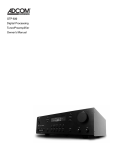
Introduction
The ACE-615 is a very carefully engineered product designed to protect
your audio, video, and computer systems while providing them with clean
AC power. The surge protection is a nonsacrificial patented technology
(U.S. patents 4,870,534 and 4,870,528) that conforms to the strictest
Federal Guidelines for surge protection.
ACE-615
AC enhancer
A C E - 6 1 5
b
fb
fa gb
accessories
amplifiers
unswitched
c
d
e
1@
ga
in
accessories (switched 30 sec delay on turn-off)
unswitched
amplifiers (switched 10 sec delay on turn-on)
in
in
PRE
out
out
UIT BREA
T
in
12v trigger
SE
out
max 300W
KER
Surge Protector and AC Enhancer model ACE-615
voltage: 120V AC/60Hz, internal power consumption: 10w max
max 1500W
coax 2
CIRC
circuit breaker
coax 1
SS T RE
O
15A
GND
phone 1
phone 2
WARNING: For indoor use in dry locations only.
serial #
To reduce the risk of shock, do not expose this unit
to rain or moisture.
hb
i b ia
10 Timber Lane
Marlboro, NJ 07746 USA
Made in the USA
dryers and heaters must not be plugged into these AC receptacles. Never allow total power
consumption of all equipment connected to these outlets to exceed 1800 watts.
ha
power 120v 60Hz
max 1800W
1#
j
AC Enhancer
WARNING: Equipment with high-current requirements, such as hobby arc-welders, hair
1)
1$
1!
owner’s manual
Safety Instructions
Unpacking
• Read all instructions and store them for future reference.
• Plug unit into polarized AC outlets only. Contact an
electrician if there is any doubt that the outlet is
properly polarized.
• Install in a properly ventilated location, away from
heaters, heat ducts and other heat producing devices.
• Do not use with high-current devices such as hobby arc
welders, hair dryers, and space heaters. Total power
consumption of connected equipment must not exceed
1800 watts.
• Do not use a unit if there are any signs of damage.
• No user serviceable parts inside. Do not attempt
servicing of this unit yourself. Refer servicing to
qualified service personnel.
• All Satellite/DSS, Cable, and Antenna cables must be
grounded in accordance with Section 810 of the
National Electrical Code and ANSI/NFPA No. 70-1984.
Failure to comply with these codes will void all
warranties regarding the ACE-615.
Before each ACE-615 left the factory, it was carefully
inspected for physical imperfections as a routine part of
ADCOM’s systematic quality control. This, along with full
operational and mechanical testing, should insure a
product flawless in both appearance and performance.
After you have unpacked the ACE-615, inspect it for
physical damage. Save the shipping carton and all
packing materials, as they are intended to minimize the
possibility of transportation damage, should the product
ever need to be shipped again. In the unlikely event
damage has occurred, notify your dealer immediately and
request the name of the carrier so that a written claim to
cover the damage can be initiated.
The right to any claim against a public carrier can be
forfeited if the carrier is not notified promptly in writing and
if the shipping carton and packing materials are not
available for inspection. Save all packing materials until
the claim has been settled.
Symbol explanations
For maximum performance and extended product life,
install the ACE-615 in a well ventilated area away from
external heat sources like radiators and heat vents.
For professional installations, the ACE-615 may be
mounted in a standard 19-inch rack using the optional
RM-3 rack-mount adapters available through ADCOM
dealers.
Installation
Connections
This “lightning flash with arrowhead” symbol is
intended to alert the user of the presence of
uninsulated “dangerous voltage” within the products
enclosure that may be of sufficient magnitude to
constitute a risk of electric shock to persons.
This exclamation point symbol is intended to alert the
user to the presence of important operating and
maintenance (servicing) instructions in the literature
accompanying the appliance.
Optional: Attach the supplied color-coded AC cord
labels to each AC cord to be installed. Place a label at
each end of the AC cord to easily identify which cord is
connected to each product.
System AC Connections
Begin by connecting products which require full-time
AC power to the rear panel jacks labeled “unswitched” 1).
Connect the amplifiers’ power cord to the rear AC jacks
labeled “amplifiers” 1!. Connect the AC power cords of all
other products to the switched jacks on the rear panel
labeled “accessories” j.
Grounding Screw
The grounding screw 1# provides a convenient system
grounding point where one or more of the components is
not equipped with a three prong AC cord. The entire
system can be grounded by simply connecting a wire
between the chassis of any system component and the
ACE-615 grounding screw 1#. (The remaining components will be grounded to the ACE-615 through the
various audio and video coax connections.)
Remote Triggering
The ACE-615 may be remotely activated and deactivated using a low voltage trigger signal available from
most contemporary preamps and receivers. Connect the
trigger out jack of the preamp with the ACE-615’s 12v
trigger in jack 1@.
Sat/DSS and Cable Connection
Connect the incoming coax cable to the coax 1 input
jack fa. Connect the corresponding coax 1 output jack
fb to the appropriate input jack of a cable box, SAT/DSS
receiver, or TV/Monitor. For a second device follow the
same procedure using the coax 2 input ga and the coax
2 output gb.
NOTE: All outdoor cables must be properly grounded
prior to entering a building. See the Safety
Instructions section for further details.
Phone Line
Connect the phone line from the wall outlet to the
phone 1 input jack ha. Connect the corresponding phone
1 output jack hb to the line input of a modem, DVD/TiVo,
DSS receiver, or pay-per-view cable box. For a second
device follow the same procedure using the phone 2
input ia and phone 2 output ib.
AC Power Connection
Once the installation and all necessary connections are
made, insure all connected equipment is off, and that the
ACE-615 power button b is in the Off (out) position. Now
plug the AC power cord 1$ into a grounded AC wall outlet.
The unit is ready for operation.
Operation
Front Panel Control
The unswitched front panel LED e indicates that AC
current is passing through the ACE-615 and into the
components connected to the unswitched AC rear
panel outlets 1). The unswitched LED e is always on
provided the unit is plugged into an active AC source.
To prevent turn-on thump, the jacks for the accessories
and amplifiers have seperate relays. When the ACE-615 is
turned on, the accessories power up before the amplifiers.
When powering down, the relay works in reverse. These
delays are in effect both with the 12V trigger source, and
without, and the duration may be adjusted by your authorized ADCOM dealer.
Press the ACE-615 power button b to activate the unit.
The power LED b, accessories LED c, and amplifiers
LED d will glow red. AC power is being supplied to all
connected components.
Remote 12v Trigger Control
* Note: This section only applies when an external trigger is
connected to the 12v trigger in jack 1@.
* Note: The unit only responds to an external trigger when the
power button b is pressed in. The power button b can
be used to override the 12v trigger input and turn the
ACE-615 off.
indicating it is waiting for an external 12v trigger to power
on. Turn on the component supplying the 12v trigger. The
ACE-615 power button LED b and switched LED c and
amplifiers LED d will glow red indicating AC power is
being supplied to all connected components. Turn off
the 12v trigger supply to return the ACE-615 to
standby mode.
Press the ACE-615 power button b to put the unit
into standby mode. The power LED b will glow amber
Typical Connections
to preamp
to device
from wall
in
accessories (switched 30 sec delay on turn-off)
unswitched
amplifiers (switched 10 sec delay on turn-on)
in
in
PRE
out
out
UIT BREA
T
in
12v trigger
SE
out
max 300W
KER
Surge Protector and AC Enhancer model ACE-615
voltage: 120V AC/60Hz, internal power consumption: 10w max
max 1500W
coax 2
CIRC
circuit breaker
coax 1
SS T RE
O
15A
GND
phone 1
phone 2
WARNING: For indoor use in dry locations only.
To reduce the risk of shock, do not expose this unit
to rain or moisture.
serial #
WARNING: Equipment with high-current requirements, such as hobby arc-welders, hair
dryers and heaters must not be plugged into these AC receptacles. Never allow total power
consumption of all equipment connected to these outlets to exceed 1800 watts.
10 Timber Lane
Marlboro, NJ 07746 USA
Made in the USA
power 120v 60Hz
max 1800W
to AC outlet
amplifier one
amplifier two
vcr
preamp
DVD player
compact disc player
laser disc player
television
from wall
to device
Trouble shooting
Symptom
Possible Causes
-Unswitched LED does not come on when the ACE-615 AC power cord is
plugged into an outlet
-Outlet may be shut off at the main breaker box
-Power button pushed in, but switched outlets are off and power LED glows
amber
-Unit may be in standby mode
-Remove any plug in the 12v trigger jack
-ACE-615 does not respond to 12v input
-Power button must be pressed in for remote activation
-The trigger voltage maybe outside the allowable +
- (5-12) volts
-No delay between accessories and amplifiers outlets
-Delay settings are incorrect. Return to authorized dealer for adjustment.
Factory settings are approximately ten seconds for amplifier turn-on and
thirty seconds for accessories turn-off.
Technical Specifications
Servicing
Electrical
Input power..........................................120VAC, +/-10%, 5-/60Hz
Protection.......................................................15A Circuit Breaker
Internal Power Consumption.........................Less than 5 watts
Control Input..................................................+/-5V to 24V AC/DC
Total Output................................................................................15A
Environmental: Operating Temperature...............0 to +50 C
Storage Temperature...............-40 to +80 C
Filter
Noise: Normal Mode................-5dB at 5kHz; -38 dB at 300kHz
Common Mode........-3dB at 300kHz; -40 dB at 1 MHz
Surge Protection
Endurance................................................1,000 surges 6 kV; 3 kA
Clamping.............................................................................172 volts
Response Time........................................................................0 sec.
(Passive protection / always on)
Maximum Applied Pulse (Combination Wave):
• Voltage: 6,000 volts
• Current: Unlimited due to current limiting
• Joules: Unlimited due to current limiting
Mechanical
Dimensions....17”(430mm) x 12” (305mm) x 3.5”(89mm)
Weight..........................................................................10 lbs. (2.7 kg)
AC Cord............................................................................6 ft. (1.8m)
ADCOM has a technical service department to answer
questions pertaining to the installation and operation of your
unit. In the event of difficulty, please contact us for prompt
advice. If your problem can not be resolved through our
combined efforts, we may refer you to an authorized repair
agency, or authorize return of the unit to the factory. To aid us
in directing you to a convenient service station, please
indicate which major city is accessible to your home.
Phone or Fax inquiries to:
Phone (732) 683-2356
Fax (732) 683-9790
Mon - Fri 9AM - 5PM EST
Please direct inquiries to:
ADCOM Service Department
Please include a return phone or fax number for the reply.
email and website info:
www.adcom.com
[email protected]
Please include a return e-mail address for the reply.
Please address all mail inquires to:
ADCOM Service Corporation
10 Timber Lane
Marlboro, NJ 07746 USA
Please include a return address for the reply.