1
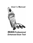
User’s Manual
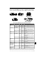
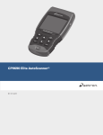
9640 Professional
Enhanced Scan Tool
Scan Tool Information
Complete the following list using the
function “Tool Information”. Provide
this information when contacting
customer support.
Serial No:
SW ID:
HW Ver:
Boot Ver:
Prod ID:
Board ID:
Burn Date:
Burn Loc:
Copyright Information
Copyright © 2005 SPX Corporation.
All rights reserved.
The information, specifications and illustrations in this
manual are based on the latest information available at the
time of printing. SPX Corporation reserves the right to
make changes at any time without notice.
Safety Precautions
For your safety, read this manual thoroughly before operating your Professional
Enhanced Scan Tool. Always refer to and follow safety messages and test
procedures provided by the manufacturer of the vehicle or equipment being
tested.
Your scan tool is intended for use by properly trained, skilled professional
automotive technicians. The safety messages presented below and throughout
this user’s manual are reminders to the operator to exercise extreme care when
using this test instrument.
Read All Instructions
Read, understand and follow all safety messages and instructions in this
manual and on the test equipment. Safety messages in this section of the
manual contain a signal word with a three-part message and, in some
instances, an icon. The signal word indicates the level of the hazard in a
situation.
Safety Messages
Safety messages are provided to help prevent personal injury and equipment
damage. All safety messages are introduced by a signal word indicating the
hazard level. The types of safety messages are:
! DANGER
Indicates an imminently hazardous situation which, if not
avoided, will result in death or serious injury to the operator
or to bystanders.
! WARNING
Indicates a potentially hazardous situation which, if not
avoided, could result in death or serious injury to the
operator or to bystanders.
! CAUTION
Indicates a potentially hazardous situation which, if not
avoided, may result in moderate or minor injury to the
operator or to bystanders.
IMPORTANT
Indicates a situation which, if not avoided, may result in
damage to the test equipment or vehicle.
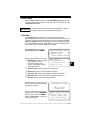
Safety messages contain three different type styles.
• Normal type states the hazard.
• Bold type states how to avoid the hazard.
• Italic type states the possible consequences of not avoiding the hazard.
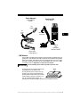
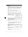
An icon, when present, gives a graphical description of the potential hazard.
Example:
Engine systems can malfunction expelling fuel, oil vapors, hot
steam, hot toxic exhaust gases, acid, refrigerant and other
debris.
Wear safety goggles and protective gloves, user and
bystander. Everyday eyeglasses only have impact resistant
lenses, they are NOT safety glasses.
Engine systems that malfunction can cause injury.
• • • • • • • • • • • • • • • • • • • • • • • • • • • • • • • • • • • • • • • • • • • • • • • • • • • • • • Safety – i
!
Safety Precautions
! Important Safety Instructions
Risk of electric shock.
• Do not exceed voltage limits between inputs as indicated
in the “Specifications”.
• Use extreme caution when working with circuits that have
greater than 60 volts DC or 24 volts AC.
Electric shock can cause injury.
! WARNING
! WARNING
! WARNING
Risk of explosion.
• Wear safety goggles and protective clothing, user and
bystander. Everyday eyeglasses only have impact
resistant lenses, they are NOT safety glasses.
• Do not use this system in environments where explosive
vapor may collect, such as in below-ground pits, confined
areas, or areas that are less than 18 inches above the floor.
• Use this equipment in locations with mechanical
ventilation providing at least four air changes per hour.
• Flammable fuel and vapors can ignite.
• Do not smoke, strike a match, or cause a spark in the
vicinity of the battery. Battery gases can ignite.
• Avoid making accidental connection between battery
terminals. Do not place uninsulated metal tools on the
battery.
• When removing battery cables, remove ground cable first.
• Avoid sparks when connecting or disconnecting power
leads to battery.
• Be sure ignition is OFF, headlights and other accessories
are OFF and vehicle doors are closed before
disconnecting battery cables. This also helps prevent
damage to on-board computer systems.
• Always disconnect battery ground connections before
servicing electrical system components.
Explosion can cause injury.
Risk of poisoning.
• Use this equipment in locations with mechanical
ventilation providing at least four air changes per hour.
Engine exhaust contains odorless lethal gas.
• Route exhaust outside while testing with engine running.
Poisoning can result in death or serious injury.
Battery acid is a highly corrosive sulfuric acid.
• Wear safety goggles and protective gloves, user and
bystander. Everyday eyeglasses only have impact
resistant lenses, they are NOT safety glasses.
• Make sure someone can hear you or is close enough to
provide aid when working near a battery.
• Have plenty of fresh water and soap nearby. If battery acid
contacts skin, clothing, or eyes, flush exposed area with
soap and water for 10 minutes.
• Seek medical help.
• Do not touch eyes while working near battery.
Battery acid can burn eyes and skin.
Risk of fire.
• Wear safety goggles and protective clothing, user and
bystander. Everyday eyeglasses only have impact
resistant lenses, they are NOT safety glasses.
Safety – ii • • • • • • • • • • • • • • • • • • • • • • • • • • • • • • • • • • • • • • • • • • • • • • • • • • • • •
Safety Precautions
• Do not position head directly over or in front of throttle
body. Do not pour gasoline down throttle body when
cranking or running engine, when working with fuel
delivery systems or any open fuel line. Engine backfire
can occur when air cleaner is out of position.
• Do not use fuel injector cleaning solvents when
performing diagnostic testing.
• Keep cigarettes, sparks, open flame and other sources of
ignition away from vehicle.
• Keep a dry chemical (Class B) fire extinguisher rated for
gasoline, chemical and electrical fires in work area.
Fire can cause death or serious injury.
Risk of flying particles.
Wear safety goggles while using electrical equipment.
Electrical equipment or rotating engine parts can cause
flying particles.
Flying particles can cause eye injury.
Risk of burns.
Batteries can produce a short-circuit current high enough
to weld jewelry to metal. Remove jewelry such as rings,
bracelets and watches before working near batteries.
Short circuits can cause injury.
! WARNING
Risk of burns.
• Do not remove radiator cap unless engine is cold.
Pressurized engine coolant may be hot.
• Do not touch hot exhaust systems, manifolds, engines,
radiators, sample probe, etc.
• Wear insulated gloves when handling hot engine
components.
• Tester leads can become hot after extended testing in
close proximity to manifolds etc.
Hot components can cause injury.
Risk of expelling fuel, oil vapors, hot steam, hot toxic exhaust
gases, acid, refrigerant and other debris.
• Wear safety goggles and protective clothing, user and
bystander. Everyday eyeglasses only have impact
resistant lenses, they are NOT safety glasses.
• Engine systems can malfunction expelling fuel, oil
vapors, hot steam, hot toxic exhaust gases, acid,
refrigerant and other debris.
Fuel, oil vapors, hot steam, hot toxic exhaust gases, acid,
refrigerant and other debris can cause serious injury.
The engine compartment contains electrical connections and
hot or moving parts.
• Keep yourself, test leads, clothing and other objects clear
of electrical connections and hot or moving engine parts.
• Do not wear watches, rings, or loose fitting clothing when
working in an engine compartment.
• Do not place test equipment or tools on fenders or other
places in the engine compartment.
• Barriers are recommended to help identify danger zones
in test area.
• Prevent personnel from walking through immediate test
area.
Contact with electrical connections and hot or moving parts
can cause injury.
• • • • • • • • • • • • • • • • • • • • • • • • • • • • • • • • • • • • • • • • • • • • • • • • • • • • • Safety – iii
!
Safety Precautions
Risk of injury.
• This equipment should be operated by qualified
personnel only.
• Use this equipment only as described in this manual. Use
only the manufacturer’s recommended attachments.
• Do not operate equipment with a damaged cord or if the
equipment has been dropped or damaged, until it has
been examined by a qualified service representative.
Operation of this equipment by anyone other than qualified
personnel may result in injury.
!
! WARNING
PRNDL2
! CAUTION
! CAUTION
! DANGER
Risk of unexpected vehicle movement.
• Block drive wheels before performing a test with engine
running.
• Unless instructed otherwise, set parking brake and put
gear selector in neutral for standard transmissions or park
for automatic transmissions.
• If vehicle has an automatic parking brake release,
disconnect release mechanism for testing and reconnect
when testing is completed.
• Do not leave a running engine unattended.
A moving vehicle can cause injury.
Risk of equipment or circuit damage.
• Unless specifically directed by the manufacturer, make
sure the ignition is OFF before connecting or
disconnecting connectors or any vehicle electrical
terminals.
• Do not create a short between battery terminals with a
jumper wire or tools.
Improper equipment use can cause equipment or circuit
damage.
Misdiagnosis may lead to incorrect or improper repair and/or
adjustment.
Do not rely on erratic, questionable, or obviously erroneous
test information or results. If test information or results are
erratic, questionable, or obviously erroneous, make sure
that all connections and data entry information are correct
and that the test procedure was performed correctly. If test
information or results are still suspicious, do not use them
for diagnosis.
Improper repair and/or adjustment may cause vehicle or
equipment damage or unsafe operation.
Some vehicles are equipped with air bags. You must follow
vehicle service manual’s warnings when working around the
air bag components or wiring. If the service manual’s instructions are not followed, the air bag may open up unexpectedly,
resulting in personal injury. Note that the air bag can still open
up several minutes after the ignition key is off (or even if the
vehicle battery is disconnected) because of a special energy
reserve module.
Safety – iv • • • • • • • • • • • • • • • • • • • • • • • • • • • • • • • • • • • • • • • • • • • • • • • • • • • •
Safety
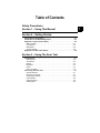
Table of Contents
ToC
!
Section 1 –––––––––– Using this Manual
1
Section 2 –––––––––––– Getting Started
2
Section 3 ––––––––Using The Scan Tool
3
Section 4 ––– Global OBD II Diagnostics
4
Section 5 –––––––––––– GM Diagnostics
5
Section 6 ––––––––––– Ford Diagnostics
6
Section 7 ––––––––Chrysler Diagnostics
7
Section 8 ––––––––– Import Diagnostics
8
Section 9 ––––––– Help & Troubleshooting
9
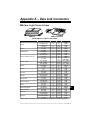
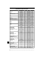
Appendix A ––––– Data Link Connectors
A
Appendix B –––––––––––––––– Glossary
B
Section 1 – Using This Manual
This manual contains instructions for use and setup of your scan tool. A table
of contents and glossary are provided to make this manual easy to use.
Some of the information shown in text or illustrations is obtained using optional
equipment. A Sales Representative can determine option availability.
This section contains a list of conventions used.
1
Safety Messages
Refer to “Safety Precautions” on page i.
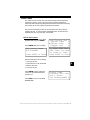
Check Note
A check note provides additional information about the subject in the preceding
paragraph.
Example:
✓
Make sure the printer is turned on, on-line and connected.
Equipment Tips and Lists
Equipment tips and lists provide information that applies to specific equipment.
Each tip is introduced by this icon ❒ for easy identification.
Example:
❒ Observe all vehicle and/or equipment manufacturer’s cautions and
warnings when testing with the scan tool.
Equipment Damage
Situations arise during testing that could damage the vehicle or the test
equipment. The word IMPORTANT signals these situations.
Example:
IMPORTANT
Failure to follow these instructions could damage the scan tool.
••••••••••••••••••••••••••••••••••••••••••••••••••••••••• 1–1
Using This Manual
Functions and Selections
Diagnostic and tool functions performed by the scan tool are highlighted in bold.
Example:
The View Data function allows you to view the vehicle’s Parameter
Identification (PID) data in real time.
1
Menus
The menus on the scan tool display are referenced in the procedures and are
highlighted in bold-italic text.
Example:
When the OBDII Function List menu displays, the scan tool is ready for use.
Questions and Responses
Messages and user responses are CAPITALIZED.
Example:
The Scan Tool displays the Pending DTCs or a message stating SYSTEM
PASS: NO FAULT DETECTED.
Manual References
Used to reference other sections of the manual. References include the “Title”
and page number (section-page).
Example:
For more information on DTCs, refer to “Diagnostic Link Connectors (DLC)”
on page 2-5.
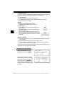
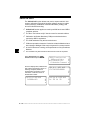
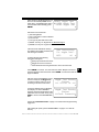
Screens
Certain Help messages, information, and data that are displayed on the scan
tool are also shown in graphical text boxes. The screens are presented as
examples and may change as the software is updated.
Example:
Main Menu
` Vehicle Diagnosis
Tool Setup
Tool Self-Tests
?
[
~
1–2 ••••••••••••••••••••••••••••••••••••••••••••••••••••••••
Safety Precautions
Section 1 – Using This Manual
Section 2 – Getting Started
Vehicle Service Information . . . . . . . . . . . . . . . . . . . . . . . . . . . . . . . . . . . . 2-1
Introduction to On-Board Diagnostics . . . . . . . . . . . . . . . . . . . . . . . . . . . 2-2
Diagnostic Link Connectors (DLC) . . . . . . . . . . . . . . . . . . . . . . . . . . . . . . 2-4
OBD II (J1962) . . . . . . . . . . . . . . . . . . . . . . . . . . . . . . . . . . . . . . . . . . . . 2-4
Ford Historic . . . . . . . . . . . . . . . . . . . . . . . . . . . . . . . . . . . . . . . . . . . . . . 2-5
GM Historic . . . . . . . . . . . . . . . . . . . . . . . . . . . . . . . . . . . . . . . . . . . . . . . 2-8
Chrysler Historic . . . . . . . . . . . . . . . . . . . . . . . . . . . . . . . . . . . . . . . . . . . 2-8
Diagnostic Trouble Codes (DTCs) . . . . . . . . . . . . . . . . . . . . . . . . . . . . . . . 2-9
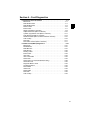
Section 3 – Using The Scan Tool
The Scan Tool . . . . . . . . . . . . . . . . . . . . . . . . . . . . . . . . . . . . . . . . . . . . . . . 3-1
Specifications . . . . . . . . . . . . . . . . . . . . . . . . . . . . . . . . . . . . . . . . . . . . . 3-2
Accessories . . . . . . . . . . . . . . . . . . . . . . . . . . . . . . . . . . . . . . . . . . . . . . 3-2
Display . . . . . . . . . . . . . . . . . . . . . . . . . . . . . . . . . . . . . . . . . . . . . . . . . . 3-2
Keyboard . . . . . . . . . . . . . . . . . . . . . . . . . . . . . . . . . . . . . . . . . . . . . . . . 3-2
Power . . . . . . . . . . . . . . . . . . . . . . . . . . . . . . . . . . . . . . . . . . . . . . . . . . . 3-3
Scan Tool Setup . . . . . . . . . . . . . . . . . . . . . . . . . . . . . . . . . . . . . . . . . . . 3-4
Connecting The Scan Tool . . . . . . . . . . . . . . . . . . . . . . . . . . . . . . . . . . . . . 3-7
Vehicle Selection . . . . . . . . . . . . . . . . . . . . . . . . . . . . . . . . . . . . . . . . . . 3-7
Keep Current Vehicle . . . . . . . . . . . . . . . . . . . . . . . . . . . . . . . . . . . . . . . 3-7
Changing the Vehicle . . . . . . . . . . . . . . . . . . . . . . . . . . . . . . . . . . . . . . . 3-8
User Interface . . . . . . . . . . . . . . . . . . . . . . . . . . . . . . . . . . . . . . . . . . . . . 3-9
User Responses . . . . . . . . . . . . . . . . . . . . . . . . . . . . . . . . . . . . . . . . . . . 3-9
Viewing Data . . . . . . . . . . . . . . . . . . . . . . . . . . . . . . . . . . . . . . . . . . . . . . 3-9
ToC
Table of Contents
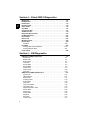
Section 4 – Global OBD II Diagnostics
ToC
Manual Info . . . . . . . . . . . . . . . . . . . . . . . . . . . . . . . . . . . . . . . . . . . . . . . . . . 4-1
I/M Readiness . . . . . . . . . . . . . . . . . . . . . . . . . . . . . . . . . . . . . . . . . . . . . . . . 4-1
Read Codes . . . . . . . . . . . . . . . . . . . . . . . . . . . . . . . . . . . . . . . . . . . . . . . . . 4-3
Pending Codes . . . . . . . . . . . . . . . . . . . . . . . . . . . . . . . . . . . . . . . . . . . . . . . 4-4
Erase Codes . . . . . . . . . . . . . . . . . . . . . . . . . . . . . . . . . . . . . . . . . . . . . . . . . 4-5
View Data . . . . . . . . . . . . . . . . . . . . . . . . . . . . . . . . . . . . . . . . . . . . . . . . . . . 4-6
View Freeze Data . . . . . . . . . . . . . . . . . . . . . . . . . . . . . . . . . . . . . . . . . . . . . 4-7
O2 Monitor Test . . . . . . . . . . . . . . . . . . . . . . . . . . . . . . . . . . . . . . . . . . . . . . 4-8
Diagnostic Monitor Tests . . . . . . . . . . . . . . . . . . . . . . . . . . . . . . . . . . . . . . 4-9
On-Board Systems . . . . . . . . . . . . . . . . . . . . . . . . . . . . . . . . . . . . . . . . . . . 4-11
Record Data . . . . . . . . . . . . . . . . . . . . . . . . . . . . . . . . . . . . . . . . . . . . . . . . 4-12
Vehicle Info . . . . . . . . . . . . . . . . . . . . . . . . . . . . . . . . . . . . . . . . . . . . . . . . . 4-14
Modules Present . . . . . . . . . . . . . . . . . . . . . . . . . . . . . . . . . . . . . . . . . . . . 4-16
Review Data . . . . . . . . . . . . . . . . . . . . . . . . . . . . . . . . . . . . . . . . . . . . . . . . 4-18
Playback . . . . . . . . . . . . . . . . . . . . . . . . . . . . . . . . . . . . . . . . . . . . . . . 4-18
Print Data . . . . . . . . . . . . . . . . . . . . . . . . . . . . . . . . . . . . . . . . . . . . . . . . . . 4-20
Printing Data (except Playback) . . . . . . . . . . . . . . . . . . . . . . . . . . . . . . 4-20
Printing Playback Data . . . . . . . . . . . . . . . . . . . . . . . . . . . . . . . . . . . . . 4-21
Code Lookup . . . . . . . . . . . . . . . . . . . . . . . . . . . . . . . . . . . . . . . . . . . . . . . 4-22
Section 5 – GM Diagnostics
GM Historic (OBD I) Diagnostics . . . . . . . . . . . . . . . . . . . . . . . . . . . . . . . . 5-1
Manual Info . . . . . . . . . . . . . . . . . . . . . . . . . . . . . . . . . . . . . . . . . . . . . . 5-1
Read Codes . . . . . . . . . . . . . . . . . . . . . . . . . . . . . . . . . . . . . . . . . . . . . . 5-1
Erase Codes . . . . . . . . . . . . . . . . . . . . . . . . . . . . . . . . . . . . . . . . . . . . . 5-2
View Data . . . . . . . . . . . . . . . . . . . . . . . . . . . . . . . . . . . . . . . . . . . . . . . . 5-4
Record Data . . . . . . . . . . . . . . . . . . . . . . . . . . . . . . . . . . . . . . . . . . . . . . 5-5
Review Data . . . . . . . . . . . . . . . . . . . . . . . . . . . . . . . . . . . . . . . . . . . . . . 5-6
Field Service . . . . . . . . . . . . . . . . . . . . . . . . . . . . . . . . . . . . . . . . . . . . . 5-8
Code Lookup . . . . . . . . . . . . . . . . . . . . . . . . . . . . . . . . . . . . . . . . . . . . 5-10
Print Data . . . . . . . . . . . . . . . . . . . . . . . . . . . . . . . . . . . . . . . . . . . . . . . 5-10
GM Enhanced (OBD II) Diagnostics . . . . . . . . . . . . . . . . . . . . . . . . . . . . . 5-11
Manual Info . . . . . . . . . . . . . . . . . . . . . . . . . . . . . . . . . . . . . . . . . . . . . 5-11
I/M Readiness . . . . . . . . . . . . . . . . . . . . . . . . . . . . . . . . . . . . . . . . . . . 5-11
Read Codes . . . . . . . . . . . . . . . . . . . . . . . . . . . . . . . . . . . . . . . . . . . . . 5-11
Pending Codes . . . . . . . . . . . . . . . . . . . . . . . . . . . . . . . . . . . . . . . . . . 5-13
Erase Codes . . . . . . . . . . . . . . . . . . . . . . . . . . . . . . . . . . . . . . . . . . . . 5-13
View Data . . . . . . . . . . . . . . . . . . . . . . . . . . . . . . . . . . . . . . . . . . . . . . . 5-13
View Freeze Data . . . . . . . . . . . . . . . . . . . . . . . . . . . . . . . . . . . . . . . . 5-15
O2 Monitor Test . . . . . . . . . . . . . . . . . . . . . . . . . . . . . . . . . . . . . . . . . . 5-15
Diagnostic Monitor Tests . . . . . . . . . . . . . . . . . . . . . . . . . . . . . . . . . . . 5-15
Record Data . . . . . . . . . . . . . . . . . . . . . . . . . . . . . . . . . . . . . . . . . . . . . 5-16
Vehicle Info . . . . . . . . . . . . . . . . . . . . . . . . . . . . . . . . . . . . . . . . . . . . . 5-16
Review Data . . . . . . . . . . . . . . . . . . . . . . . . . . . . . . . . . . . . . . . . . . . . . 5-16
Playback . . . . . . . . . . . . . . . . . . . . . . . . . . . . . . . . . . . . . . . . . . . . . . . 5-16
Print Data . . . . . . . . . . . . . . . . . . . . . . . . . . . . . . . . . . . . . . . . . . . . . . . 5-17
Code Lookup . . . . . . . . . . . . . . . . . . . . . . . . . . . . . . . . . . . . . . . . . . . . 5-17
ii
Ford Historic Self-Test Routines . . . . . . . . . . . . . . . . . . . . . . . . . . . . . . . . 6-1
Manual Info . . . . . . . . . . . . . . . . . . . . . . . . . . . . . . . . . . . . . . . . . . . . . .. 6-1
Read KOEO Codes . . . . . . . . . . . . . . . . . . . . . . . . . . . . . . . . . . . . . . . .. 6-1
Read KOER Codes . . . . . . . . . . . . . . . . . . . . . . . . . . . . . . . . . . . . . . . .. 6-3
Review Codes . . . . . . . . . . . . . . . . . . . . . . . . . . . . . . . . . . . . . . . . . . . .. 6-6
Erase Codes . . . . . . . . . . . . . . . . . . . . . . . . . . . . . . . . . . . . . . . . . . . . .. 6-7
Wiggle Test (EEC-IV Vehicles) . . . . . . . . . . . . . . . . . . . . . . . . . . . . . . .. 6-8
Output Switch Test (EEC-IV Vehicles) . . . . . . . . . . . . . . . . . . . . . . . .. 6-10
Cylinder (Cyl) Balance Test (EEC-IV Vehicles) . . . . . . . . . . . . . . . . . .. 6-11
IVSC-Speed Ctrl (EEC-IV Vehicles) . . . . . . . . . . . . . . . . . . . . . . . . . .. 6-13
STAR Test Mode (EEC-IV, MECS and MCU Vehicles) . . . . . . . . . . .. 6-15
Code Lookup . . . . . . . . . . . . . . . . . . . . . . . . . . . . . . . . . . . . . . . . . . . .. 6-16
Print Data . . . . . . . . . . . . . . . . . . . . . . . . . . . . . . . . . . . . . . . . . . . . . . .. 6-17
DCL Data Functions (EEC-IV Vehicles) . . . . . . . . . . . . . . . . . . . . . . .. 6-17
Ford Enhanced (OBD II) Diagnostics . . . . . . . . . . . . . . . . . . . . . . . . . . . . 6-21
Manual Info . . . . . . . . . . . . . . . . . . . . . . . . . . . . . . . . . . . . . . . . . . . . .. 6-21
I/M Readiness . . . . . . . . . . . . . . . . . . . . . . . . . . . . . . . . . . . . . . . . . . .. 6-21
Read MIL DTC . . . . . . . . . . . . . . . . . . . . . . . . . . . . . . . . . . . . . . . . . . .. 6-21
Read All DTC . . . . . . . . . . . . . . . . . . . . . . . . . . . . . . . . . . . . . . . . . . . .. 6-22
Pending Codes . . . . . . . . . . . . . . . . . . . . . . . . . . . . . . . . . . . . . . . . . .. 6-22
Erase Codes . . . . . . . . . . . . . . . . . . . . . . . . . . . . . . . . . . . . . . . . . . . .. 6-23
View Data . . . . . . . . . . . . . . . . . . . . . . . . . . . . . . . . . . . . . . . . . . . . . .. 6-23
View Freeze Data . . . . . . . . . . . . . . . . . . . . . . . . . . . . . . . . . . . . . . . .. 6-24
Quick Tests . . . . . . . . . . . . . . . . . . . . . . . . . . . . . . . . . . . . . . . . . . . . .. 6-24
Quick Tests (7.3L Powerstroke Diesel Only) . . . . . . . . . . . . . . . . . . . .. 6-28
O2 Monitor Test . . . . . . . . . . . . . . . . . . . . . . . . . . . . . . . . . . . . . . . . . .. 6-32
Diagnostic Monitor Tests . . . . . . . . . . . . . . . . . . . . . . . . . . . . . . . . . . .. 6-32
On-Board Systems . . . . . . . . . . . . . . . . . . . . . . . . . . . . . . . . . . . . . . .. 6-32
Record Data . . . . . . . . . . . . . . . . . . . . . . . . . . . . . . . . . . . . . . . . . . . .. 6-32
Vehicle Info . . . . . . . . . . . . . . . . . . . . . . . . . . . . . . . . . . . . . . . . . . . . .. 6-32
Review Data . . . . . . . . . . . . . . . . . . . . . . . . . . . . . . . . . . . . . . . . . . . .. 6-32
Print Data . . . . . . . . . . . . . . . . . . . . . . . . . . . . . . . . . . . . . . . . . . . . . . .. 6-32
Code Lookup . . . . . . . . . . . . . . . . . . . . . . . . . . . . . . . . . . . . . . . . . . . .. 6-32
ToC
Section 6 – Ford Diagnostics
iii
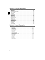
Section 7 – Chrysler Diagnostics
ToC
Manual Info . . . . . . . . . . . . . . . . . . . . . . . . . . . . . . . . . . . . . . . . . . . . . . . . . . 7-1
Read Codes . . . . . . . . . . . . . . . . . . . . . . . . . . . . . . . . . . . . . . . . . . . . . . . . . 7-1
Read Temporary Codes . . . . . . . . . . . . . . . . . . . . . . . . . . . . . . . . . . . . . . . . 7-2
Erase Codes . . . . . . . . . . . . . . . . . . . . . . . . . . . . . . . . . . . . . . . . . . . . . . . . . 7-3
View Data . . . . . . . . . . . . . . . . . . . . . . . . . . . . . . . . . . . . . . . . . . . . . . . . . . . 7-4
Freeze Frame . . . . . . . . . . . . . . . . . . . . . . . . . . . . . . . . . . . . . . . . . . . . . . . . 7-5
Record Data . . . . . . . . . . . . . . . . . . . . . . . . . . . . . . . . . . . . . . . . . . . . . . . . . 7-5
Switch Test . . . . . . . . . . . . . . . . . . . . . . . . . . . . . . . . . . . . . . . . . . . . . . . . . . 7-7
Actuator Test . . . . . . . . . . . . . . . . . . . . . . . . . . . . . . . . . . . . . . . . . . . . . . . . 7-8
Idle Speed Test . . . . . . . . . . . . . . . . . . . . . . . . . . . . . . . . . . . . . . . . . . . . . . . 7-9
Sensor Test . . . . . . . . . . . . . . . . . . . . . . . . . . . . . . . . . . . . . . . . . . . . . . . . . . 7-9
Controller Info . . . . . . . . . . . . . . . . . . . . . . . . . . . . . . . . . . . . . . . . . . . . . .. 710
Reset EMR Lamp . . . . . . . . . . . . . . . . . . . . . . . . . . . . . . . . . . . . . . . . . . . . 7-10
Set Basic Time . . . . . . . . . . . . . . . . . . . . . . . . . . . . . . . . . . . . . . . . . . . . . . 7-11
Review DATA . . . . . . . . . . . . . . . . . . . . . . . . . . . . . . . . . . . . . . . . . . . . . . . 7-12
Print Data . . . . . . . . . . . . . . . . . . . . . . . . . . . . . . . . . . . . . . . . . . . . . . . . . . 7-13
Code Lookup . . . . . . . . . . . . . . . . . . . . . . . . . . . . . . . . . . . . . . . . . . . . . . . 7-13
Section 8 – Import Diagnostics
Import Enhanced (OBD II) Diagnostics . . . . . . . . . . . . . . . . . . . . . . . . . . . 8-1
Manual Info . . . . . . . . . . . . . . . . . . . . . . . . . . . . . . . . . . . . . . . . . . . . . . 8-1
I/M Readiness . . . . . . . . . . . . . . . . . . . . . . . . . . . . . . . . . . . . . . . . . . . . 8-1
Read Codes . . . . . . . . . . . . . . . . . . . . . . . . . . . . . . . . . . . . . . . . . . . . . . 8-1
Pending Codes . . . . . . . . . . . . . . . . . . . . . . . . . . . . . . . . . . . . . . . . . . . 8-3
Erase Codes . . . . . . . . . . . . . . . . . . . . . . . . . . . . . . . . . . . . . . . . . . . . . 8-3
View Data . . . . . . . . . . . . . . . . . . . . . . . . . . . . . . . . . . . . . . . . . . . . . . . . 8-3
View Freeze Data . . . . . . . . . . . . . . . . . . . . . . . . . . . . . . . . . . . . . . . . . 8-3
O2 Monitor Test . . . . . . . . . . . . . . . . . . . . . . . . . . . . . . . . . . . . . . . . . . . 8-3
Diagnostic Monitor Tests . . . . . . . . . . . . . . . . . . . . . . . . . . . . . . . . . . . . 8-3
Record Data . . . . . . . . . . . . . . . . . . . . . . . . . . . . . . . . . . . . . . . . . . . . . . 8-3
Vehicle Info . . . . . . . . . . . . . . . . . . . . . . . . . . . . . . . . . . . . . . . . . . . . . . 8-4
Playback . . . . . . . . . . . . . . . . . . . . . . . . . . . . . . . . . . . . . . . . . . . . . . . . 8-4
Print Data . . . . . . . . . . . . . . . . . . . . . . . . . . . . . . . . . . . . . . . . . . . . . . . . 8-4
Code Lookup . . . . . . . . . . . . . . . . . . . . . . . . . . . . . . . . . . . . . . . . . . . . . 8-4
iv
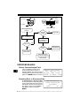
How to Use On-Line Help . . . . . . . . . . . . . . . . . . . . . . . . . . . . . . . . . . . . . . 9-1
Scan Tool Does Not Power Up . . . . . . . . . . . . . . . . . . . . . . . . . . . . . . . . . . 9-1
Using Non-OBD II Adapter Cables . . . . . . . . . . . . . . . . . . . . . . . . . . . .. 9-1
Using J1962 (OBD II) or Chrysler LH Adapter Cable . . . . . . . . . . . . . .. 9-1
Error Messages . . . . . . . . . . . . . . . . . . . . . . . . . . . . . . . . . . . . . . . . . . . . . . 9-2
Vehicle Communication Fault . . . . . . . . . . . . . . . . . . . . . . . . . . . . . . . .. 9-2
Operating Error or Erroneous Data . . . . . . . . . . . . . . . . . . . . . . . . . . . .. 9-2
Battery Replacement . . . . . . . . . . . . . . . . . . . . . . . . . . . . . . . . . . . . . . . . . . 9-3
Tool Self-Tests . . . . . . . . . . . . . . . . . . . . . . . . . . . . . . . . . . . . . . . . . . . . . . . 9-4
Display Test . . . . . . . . . . . . . . . . . . . . . . . . . . . . . . . . . . . . . . . . . . . . . .. 9-4
Keyboard Test . . . . . . . . . . . . . . . . . . . . . . . . . . . . . . . . . . . . . . . . . . . .. 9-4
Memory Test . . . . . . . . . . . . . . . . . . . . . . . . . . . . . . . . . . . . . . . . . . . . .. 9-5
Printer Test . . . . . . . . . . . . . . . . . . . . . . . . . . . . . . . . . . . . . . . . . . . . . .. 9-5
Program Mode . . . . . . . . . . . . . . . . . . . . . . . . . . . . . . . . . . . . . . . . . . . . . . . 9-6
Technical Support . . . . . . . . . . . . . . . . . . . . . . . . . . . . . . . . . . . . . . . . . . . . 9-6
ToC
Section 9 – Help & Troubleshooting
Appendix A – Data Link Connectors
Appendix B – Glossary
v
vi
ToC
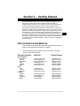
Section 2 – Getting Started
The Professional Enhanced Scan Tool was developed by experts in the
automotive service industry to help diagnose vehicles and assist in
troubleshooting procedures. The tool monitors vehicle events and retrieves
codes from the vehicle computer’s memory to pinpoint problem areas.
All information, illustrations and specifications contained in this manual are
based on the latest information available from industry sources at the time of
publication. No warranty (expressed or implied) can be made for its accuracy
or completeness, nor is any responsibility assumed by the manufacturer or
anyone connected with it for loss or damages suffered through reliance on any
information contained in this manual or misuse of accompanying product. The
manufacturer reserves the right to make changes at any time to this manual or
accompanying product without obligation to notify any person or organization
of such changes.
2
VEHICLE SERVICE INFORMATION
The following is a list of web sites and phone numbers where electronic
engine control diagnostic information is available.
✓
Some manuals may be available at your local dealer, auto parts
stores or local public libraries.
Domestic Vehicles
General Motors
Chevrolet
Pontiac
Oldsmobile
Buick
Cadillac
Saturn
Ford
Ford
Lincoln
Mercury
Chrysler
Chrysler
Dodge
Plymouth
Eagle
Web Site
Phone Number
www.chevrolet.com
www.pontiac.com
www.oldsmobile.com
www.buick.com
www.cadillac.com
www.saturn.com
1-800-551-4123
1-800-551-4123
1-800-551-4123
1-800-551-4123
1-800-333-4CAD
1-800-553-6000
www.ford.com
www.lincoln.com
www.mercury.com
1-800-392-3673
1-800-392-3673
1-800-392-3673
www.chrysler.com
www.dodge.com
Not Available
Not Available
1-800-348-4696
1-800-348-4696
1-800-348-4696
1-800-348-4696
••••••••••••••••••••••••••••••••••••••••••••••••••••••••• 2–1
Getting Started
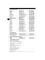
European Vehicles
2
Audi
Volkswagon
BMW
MINI
Jaguar
Volvo
Mercedes
Land Rover
Porsche
Saab
www.audi.com
www.vw.com
www.bmw.com
www.mini.com
www.jaguar.com
www.volvo.com
www.mercedes-benz.com
www.landrover.com
www.porsche.com
www.saab.com
Acura
Honda
Lexus
Scion
Toyota
Hyundai
Infiniti
Nissian
Kia
Mazda
Daewoo
Subaru
Isuzu
Geo
Mitsubishi
Suzuki
www.acura.com
www.honda.com
www.lexus.com
www.scion.com
www.toyota.com
www.hyundai.com
www.infiniti.com
www.nissianusa.com
www.kia.com
www.mazda.com
www.daewoo.com
www.subaru.com
www.isuzu.com
Not Available
www.mitsubishi.com
www.suzukiauto.com
Asian Vehicles
Web Site
1-800-544-8021
1-800-544-8021
1-201-307-4000
1-201-307-4000
1-800-4-JAGUAR
1-800-458-1552
1-800-367-6372
1-800-637-6837
1-800-PORSCHE
1-800-955-9007
Phone Number
1-800-999-1009
1-800-999-1009
1-800-255-3987
1.866.70.SCION
1-800-GO-TOYOTA
1-800-633-5151
1-800-662-6200
1-800-nissian1
1-800-333-4542
1-800-222-5500
1-822-759-2114
1-800-SUBARU3
1-800-255-6727
Not Available
1-888-MITSU2004
1-800-934-0934
Other Manuals
Chilton Book Company
Haynes Publications
Bentley Publishers
‘
www.chiltonsonline.com
1-800-347-7707
www.haynes.com
1-800-242-4637
www.bentleypublishers.com 1-800-423-4595
Repair Information Programs
Mitchell
Alldata
www.mitchell1.com
www.alldata.com
1-888-724-6742
1-800-697-2533
Suitable Manual Titles
“Diagnostic Service Manuals”
“PowerTrain Codes and Oxygen Sensors”
“Automotive Emission Control Manual”
“Fuel Injection”
“Automotive Electrics and Electronics”
“Automotive Sensors”
“Electronic Transmission Control”
“Emission Control Technology
“Engine Management”
or similar titles...
2–2 ••••••••••••••••••••••••••••••••••••••••••••••••••••••••
Getting Started
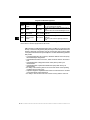
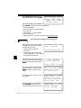
INTRODUCTION TO ON-BOARD DIAGNOSTICS
The original on-board diagnostics (OBD I) lacked consistency in
communication and interface while allowing different interpretations amongst
vehicle manufacturers. Ford and Chrysler used different types of engine control
computers and data link connectors, and GM varied the trouble codes and
communication protocols from year-to-year.
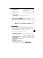
The tables below highlight changes for GM, Ford, and Chrysler. If this seems
confusing; don’t worry. Your tool makes it easy. Based on the VIN information
selected during Scan Tool setup, the processor is automatically recognized. All
you have to do is choose the correct adapter cable and jumper wires (if
necessary). Details on adapter cables and jumper wires may be found in
“Diagnostic Link Connectors (DLC)” on page 2-5
.
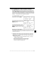
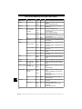
GM On-Board Diagnostics
System
Years
OBD I Control Module
OBD II Control Module
Description
Most vehicles used the 12-pin ALDL (Assembly Line Data Link)
located under the dash on the driver side. Some 94-95 vehicles
1981–1995 used the 16-pin OBD II (J1962) data link connector (DLC), but
use the Historical application software. Refer to the vehicle’s
Vehicle Emission Control Information label.
1994*-Present Complies with OBD II regulations and uses the J1962 DLC.
* OBD II system is used on certain 1994-1995 vehicles equipped with a 2.2L, 2.3L, 3.8L, 4.3L or 5.7L
engines.
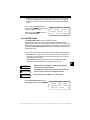
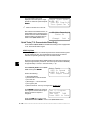
Ford On-Board Diagnostics
System
Long Name
MCU
Microprocessor Control Unit
EEC-IV
MECS
EEC-V
PTEC
Electronic Engine Control,
Fourth generation
Mazda Electronic Control
System
Electronic Engine Control,
Fifth generation
Powertrain Electronic
Controller
Years
Description
Used in police vehicles, containing carbureted
1980 –1991
engines. Uses the MCU DLC.
Most Ford vehicles equipped with North
1984 –1995
American engines. Uses the EEC-IV DLC.
Vehicles equipped with Mazda-sourced engines.
1988 –1995
Uses MECS 6-pin and 17-pin DLCs.
Complies with OBD II regulations and uses the
1994* – present
OBD II J1962 DLC.
Complies with OBD II regulations and uses the
2000 – present
OBD II J1962 DLC.
* EEC-V OBD II system used in 1994-1995 vehicles equipped with a 3.8L or 4.6L engine.
••••••••••••••••••••••••••••••••••••••••••••••••••••••••• 2–3
2
Getting Started
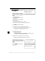
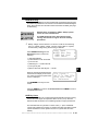
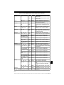
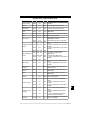
Chrysler On-Board Diagnostics
System
2
Long Name
Years
Description
SMEC
Single Module Engine
1989–1990
Controller
Used a 6-pin Serial Communication Interface (SCI)
DLC and has bidirectional capability.
SBEC
Single Board Engine
Controller
1989*–1995
Used two types of DLCs: a 6-pin SCI and a 6-pin LH
series.
The first to allow a tool to reset the EMR light on trucks.
OBD II
PCM
OBD II Powertrain
Control Module
1995**– present
Complies with OBD II regulations and uses the OBD II
J1962 DLC.
JTEC
Jeep/Truck Engine
Controller
1996– present
Complies with OBD II regulations and uses the OBD II
J1962 DLC.
The JTEC system is used on light-duty trucks and
Jeeps
* In 1989, the SBEC system was installed in selected vehicles with 3.0L V6 engines.
** Some vehicles in 1995 were equipped with the OBD II PCM.
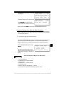
OBD II stands for On-Board Diagnostics version II. OBD II is a system that the
Society of Automotive Engineers (SAE) developed to standardize automotive
electronic diagnosis. Technicians now can use the same tool to test any OBD
II compliant vehicles without special adapters. The SAE established guidelines
that provide:
• a universal diagnostic test connector, called the data link connector (DLC),
with dedicated pin assignments.
• a standardized location for the DLC, visible under the dash on the driver’s
side.
• a standardized list of diagnostic trouble codes (DTCs) used by all
manufacturers.
• a standardized list of parameter identification (PID) data used by all
manufacturers.
• the ability of the vehicle system to record a freeze frame of the operating
conditions when a fault occurs.
• expanded diagnostic capabilities that records a code whenever a condition
occurs that effects vehicle emissions.
• the ability to clear stored codes from vehicle memory with the scan tool.
2–4 ••••••••••••••••••••••••••••••••••••••••••••••••••••••••
Getting Started
In addition, SAE has published hundreds of pages of text defining a standard
communications protocol that establishes the hardware, software, and circuit
parameters of OBD II systems. Unfortunately, vehicle manufacturers have
different interpretations of this standard communications protocol. As a result,
the generic OBD II communications scheme used will vary, depending on the
vehicle.
SAE publishes recommendations, not laws, but the Environmental Protection
Agency (EPA) and California Air Resources Board (CARB) made many of
SAE’s recommendations legal requirements that vehicle manufacturers were
required to phase in over a three-year period. Beginning in 1994, vehicles with
a new engine management computer – about 10% of each manufacturers fleet
– were supposed to comply with OBD II standards. For 1995, OBD II systems
were to appear on about 40% of the new vehicles sold in the USA. Some of the
1994-1995 OBD II systems were not fully compliant, so the Government
granted waivers to give manufacturers time to fine-tune their systems.
Beginning in 1996, most of the new vehicles sold in the USA were fully OBD II
compliant.
DIAGNOSTIC LINK CONNECTORS (DLC)
The Data Link Connector (DLC) allows the scan tool to communicate with the
vehicle’s computer(s). Before OBD II, manufacturers used different data link
connectors to communicate with the vehicle. The proper DLC adapter cable
must be used to connect the tool to the vehicle. Also, the vehicle’s DLC may be
found in several different places and have many different configurations. The
following describes the DLCs used by Ford, GM and Chrysler. The DLC location
and types for domestic vehicles can be looked up in the charts in “Appendix
A - Data Link Connectors".
••••••••••••••••••••••••••••••••••••••••••••••••••••••••• 2–5
2
Getting Started
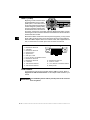
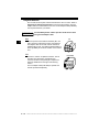
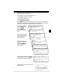
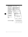
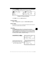
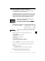
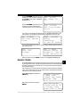
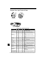
OBD II (J1962)
Beginning in 1996, vehicles sold in
the United States use the J1962
(OBD II) DLC, a term taken from a
physical and electrical specification
number assigned by SAE (J1962).
The DLC should be located under
the dashboard on the driver side of
the vehicle. If the DLC is not located under the dashboard as stated, a decal
describing its location should be attached to the dashboard in the area the DLC
should have been located.
2
Because the OBD II J1962 connector has power and ground, you only need a
single cable connection to the tool for both power and tool communications.
Attach the OBD II adapter cable to the extender cable, both supplied with the
tool, to connect the tool. Certain pins in the connector are reserved
.
1 - Manufacturer Reserved
2 - J1850 Bus+
3 - Manufacturer Reserved
4 - Chassis Ground
5 - Signal Ground
6 - CAN High, J-2284
7 - K Line, ISO 9141-2 & ISO/DIS 14230-4
8 - Manufacturer Reserved
9 - Manufacturer Reserved
10 - J1850 Bus
11 - Manufacturer Reserved
12 - Manufacturer Reserved
1
8
9
16
13 - Manufacturer Reserved
14 - CAN Low, J-2284
15 - L Line, ISO 9141-2 & ISO/DIS 14230-4
16 - Battery Power
Ford Historic
Ford used three types of DLCs with their historic (OBD I) systems. Refer to
“Appendix A - Data Link Connectors" for the adapter cable needed for your
vehicle.
IMPORTANT
Use the Battery Power cable to provide power to the scan tool
for all systems.
2–6 ••••••••••••••••••••••••••••••••••••••••••••••••••••••••
Getting Started
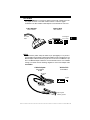
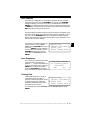
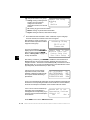
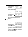
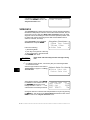
EEC-IV/MCU
The EEC-IV/MCU DLC is a large six-sided connector with a pigtail connector.
The pigtail connector is not used on MCU vehicles – leave the pigtail
unattached. The EEC-IV/MCU cable adapter is included with the scan tool.
Vehicle DLC
Cable Adapter
EEC-IV/MCU
EEC-IV/MCU
To Scan
Tool
STI Pigtail
EEC-IV only
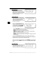
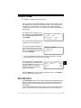
MECS
MECS vehicles (1988 –1995) use either a 6-pin (with pigtail) or a 17-pin DLC.
Use the MECS 6-pin adapter cable kit (P/N 9603) for both configurations. The
MECS adapter cable kit includes jumper wires to connect to the MECS 17-pin
DLC. The MECS adapter cable kit is not included with this tool. It is available
through your dealer. Use the following diagrams to connect the adapter cable.
6-Pin MECS
Cable Adapter
Vehicle DLC
6-Pin MECS
6-Pin MECS
P/N 9603
To Scan
Tool
P igtail
6
4 5
1 2 3
STI Pigtail
Clip to good
Vehicle ground
••••••••••••••••••••••••••••••••••••••••••••••••••••••••• 2–7
2
Getting Started
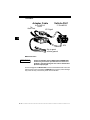
17-Pin MECS
Adapter Cable
6-Pin MECS
To
Scan Tool
P/N 9603
Vehicle DLC
17-Pin MECS
STI Pigtail
2
4
1
5
2
6
3
STO
Clip to good
vehicle ground
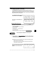
MECS Ford Probe
IMPORTANT
Certain Ford Probes have a WHITE TACH CONNECTOR
located very close to the 6-pin Self-Test connector and
bundled in the same wiring harness. This is NOT the STI
(Self Test Input) Pigtail.
Connect the pigtail to the BLACK STI connector located farther back on the wire
harness. If the tool is connected to the WHITE Tach connector, serious damage
may result and may void warranty. Refer to the illustration.
2–8 ••••••••••••••••••••••••••••••••••••••••••••••••••••••••
Getting Started
Cable Adapter
Vehicle DLC
6-Pin MECS
6-Pin MECS
P/N 9603
STI
Pigtail
To
Scan
Tool
BLACK STI
Connector
4
1
5
2
Windshield
Wiper
Motor
6
3
6-Pin MECS
6-Pin MECS
WHITE
Tach
Connector
DO NOT USE!
Clip to good
vehicle ground
GM Historic
Prior to1996, most GM vehicles used the 12-pin Assembly Line Diagnostic Link
(ALDL) DLC. The GM ALDL cable kit includes the ALDL adapter and cigarette
lighter power cable. This adapter cable is included with the scan tool. In 1994
and 1995, certain GM vehicles use the J1962 (OBD II) DLC, but are not OBD
II compliant. Refer to “Appendix A - Data Link Connectors".
IMPORTANT
Use the Battery Power cable to provide 12V to the tool.
The ALDL DLCs are usually located under
the dashboard on the driver’s side.
ALDL
On Corvettes & Fieros, the DLC may be
located in the center console behind the
F E D C B A
ashtray. Refer to vehicle service manual for
G H J K L M
exact location. It may be in full view, or it
may be recessed behind a panel. An
opening in the panel should allow access to the recessed connector.
••••••••••••••••••••••••••••••••••••••••••••••••••••••••• 2–9
2
Getting Started
Chrysler Historic
Prior to 1996, most Chrysler vehicles used either the SCI or LH DLC. Refer to
“Appendix A - Data Link Connectors" for DLC type and location. The SCI
adapter cable is included with the scan tool. The LH adapter cable (P/N 9605)
can be purchased from your dealer.
IMPORTANT
Use the Battery Power cable to provide 12V to the tool when
using the SCI adapter cable.
SCI
2
SCI
The SCI (serial communications interface) DLC is a
6-pin connector located in the engine compartment.
The adapter cable to be used on these vehicles is
supplied with the tool. This cable is labeled CHRY on
the 15 pin DB style connector and SCI on the vehicle
end.
LH
The DLC is used on LH platform vehicles. The LH
style DLC is a small, blue, rectangular 6-pin
connector located in the passenger compartment
below the dashboard to the right of the steering
column.
LH (P/N 9605)
The LH Adapter Cable (P/N 9605) is optional and
must be purchased separately.
2 – 10 • • • • • • • • • • • • • • • • • • • • • • • • • • • • • • • • • • • • • • • • • • • • • • • • • • • • • • •
Getting Started
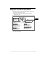
Diagnostic Trouble Codes (DTCs)
✓
Diagnostic Trouble Codes are used to help determine the cause of
a problem or problems with a vehicle.
❒ Diagnostic Trouble Codes (DTCs) consist of a five-digit
alphanumeric code.
The Diagnostic Trouble Codes format and general code types are shown below.
Bx - Body
Cx - Chassis
Px - Powertrain
Ux - Network Comm.
x = 0, 1, 2 or 3
P0 1 0 1
Specific Fault Designation
Vehicle Specific System
Example:
P0101 - Mass or Volume Air Flow Circuit Range/Performance Problem
Powertrain Codes
P0xxx - Generic (SAE)
P1xxx - Manufacturer Specific
P2xxx - Generic (SAE)
P30xx-P33xx - Manufacturer Specific
P34xx-P39xx - Generic (SAE)
Chassis Codes
C0xxx - Generic (SAE)
C1xxx - Manufacturer Specific
C2xxx - Manufacturer Specific
C3xxx - Generic (SAE)
Body Codes
B0xxx - Generic (SAE)
B1xxx - Manufacturer Specific
B2xxx - Manufacturer Specific
B3xxx - Generic (SAE)
Network Communication Codes
U0xxx - Generic (SAE)
U1xxx - Manufacturer Specific
U2xxx - Manufacturer Specific
U3xxx - Generic (SAE)
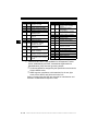
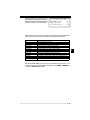
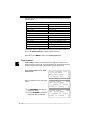
Within each general category, the DTCs are assigned to specific ranges that
cover certain vehicle systems.
• • • • • • • • • • • • • • • • • • • • • • • • • • • • • • • • • • • • • • • • • • • • • • • • • • • • • • • • 2 – 11
2
Getting Started
2
Lower Upper
Assigned DTC System
P0000 P00FF Fuel Air Metering Auxiliary
Emission Controls
P0100 P02FF Fuel Air Metering
P0300 P03FF Ignition System or Misfire
P0400 P04FF Auxiliary Emission Controls
P0500 P05FF Vehicle Speed Idle Control
Auxiliary Inputs
Computer and Auxiliary
P0600 P06FF
Outputs
P0700 P09FF Transmission
P0A00 P0AFF Hybrid Propulsion
Manufacturer Control Fuel &
P1000 P10FF Air Metering, Auxiliary
Emission Controls
P1100 P12FF Manufacturer Control Fuel &
Air Metering
Manufacturer Control Ignition
P1300 P13FF
System or Misfire
Manufacturer Control
P1400 P14FF Auxiliary emission Controls
Manufacturer Cntrl Veh.Spd.
P1500 P15FF Idle Speed Control Auxiliary
Inputs
✓
Lower
Upper
P1600 P16FF
P1700 P19FF
P2000 P22FF
P2300 P23FF
P2400 P24FF
P2500 P25FF
P2600 P26FF
P2700 P27FF
P2900 P32FF
P3300
P3400
U0000
U0100
U0300
U0400
P33FF
P34FF
U00FF
U02FF
U03FF
U04FF
Assigned DTC System
Manufacturer Control
Auxiliary Inputs Auxiliary
Outputs
Manufacturer Control
Transmission
Fuel Air Metering Auxiliary
emission Controls
Ignition System or Misfire
Auxiliary Emission Controls
Auxiliary Inputs
Computer and Auxiliary
Outputs
Transmission
Fuel Air Metering Auxiliary
Emission Controls
Ignition System
Cylinder Deactivation
Network Electrical
Network Communication
Network Software
Network Data
J2012 and ISO 15031-6 are standards for all Diagnostic Trouble
Codes, established by the SAE, International Organization for
Standardization (ISO) and other governing bodies.
❒ Codes and definitions assigned by this specification are known as
Generic OBDII codes.
❒ OBDII requires compliance to this standard, for all cars, light
trucks, APVs, MPVs, and SUVs sold in the U.S.
Codes not reserved by the SAE are reserved for manufacturer and
referred to as Manufacturer Specific Codes.
2 – 12 • • • • • • • • • • • • • • • • • • • • • • • • • • • • • • • • • • • • • • • • • • • • • • • • • • • • • • •
Section 3 – Using The Scan Tool
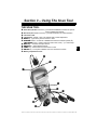
THE SCAN TOOL
B Serial Port (DB9 Male Connector) – provides a serial RS232 connection for a printer
C
D
E
F
G
H
I
J
a
b
and for updating the software.
DLC Port (DB15 Male Connector) – provides connection for vehicle interface.
12V Power Jack
LCD Display – backlit, 4 line x 20 character with contrast adjustment.
BACK key – goes to the previous screen or level.
UP/DOWN arrows – scrolls UP or DOWN and moves the selection pointer (`).
LEFT/RIGHT arrows – selects responses and moves cursor (^) in code lookup.
HELP key – accesses the Help Function.
ENTER key – selects displayed items.
FUNC key – returns back to a function list or menu.
ON/OFF key – turns power ON/OFF when not connected to vehicle.
Battery compartment cover.
C
D
E
B
F
I
G
H
j
a
b
••••••••••••••••••••••••••••••••••••••••••••••••••••••••• 3–1
3
Using The Scan Tool
Specifications
Display: Backlit LCD, 4 line, 20 column, contrast adjust
Operating Temperature: 0 to 50°C (32 to 122°F)
Storage Temperature: -20 to 70°C (-4 to 158°F)
Internal Power: 6-AAA cells
External Power: 7 to 16 Volts
✓
Most vehicle control modules require at least 8.0 V to operate properly.
Power Dissipation: 3.5 Watts maximum
Dimensions:
Height
Width
1.625"
41 mm
Weight: 3.16 lbs (1432 g)
3
5.25"
133 mm
Length
9.75"
248 mm
Accessories
Standard 8 ft Extender Cable
Battery Power Cable (includes cigarette lighter adapter)
– Battery Clip Adapter — Optional
Adapter Cables: Standard OBD II (J1962) cable — Included
GM ALDL cable kit — Included
Ford EEC-IV/MCU cable kit — Included
Chrysler SCI cable kit — Included
9605 Chrysler LH cable kit — Optional
9603 Ford Probe/MECS cable kit — Optional
Optional / Replacement Parts are available from the:
• dealer where you originally purchased your tool.
• manufacturer contact customer service at 1-800-228-7667 (8:00 – 6:00 EST
Monday – Friday) .
3–2 ••••••••••••••••••••••••••••••••••••••••••••••••••••••••
Using The Scan Tool
Display
The scan tool uses a 4 line by 20 character, back-lit Liquid Crystal Display
(LCD). The large viewing area displays messages, instructions, and diagnostic
information. The contrast can be adjusted.
Seven characters help you navigate
and operate the scan tool:
? appears in upper right corner of
display to indicate Help is available.
` identifies the selection.
[ indicates additional information is
]
«
~
Function List
` 2)Read DTC(Codes)
3)Erase DTC(Codes)
4)View Data
?
]
[
~
available on the next screen.
indicates additional information is available on the previous screen.
identifies selected items in data lists.
Bell in lower right corner means the sound alert is on or active.
Low battery symbol will appear in bottom right-hand corner of the screen
at power-up if the internal batteries need replacement or are not installed.
Keyboard
The scan tool’s software is designed for ease in operating and navigating
through menus. Do not use solvents such as alcohol to clean the keypad or
display. Use a mild nonabrasive detergent and a soft cotton cloth. Do not soak
the keypad as water might find its way inside the scan tool.
••••••••••••••••••••••••••••••••••••••••••••••••••••••••• 3–3
3
Using The Scan Tool
Power
✓
Refer to “Scan Tool Does Not Power Up” on page 9-1 if you encounter
problems.
Internal Batteries
When the scan tool is not connected to the vehicle, the ON/OFF key turns ON
the scan tool. Press and hold down the ON/OFF key for at least one second to
turn ON the scan tool.
To conserve battery power, the scan tool disables the display’s back-lighting
and turns OFF after a period of inactivity.
Each time the scan tool is powered up, the voltage of the batteries is checked.
If the voltage is low, the Low Battery Symbol () displays on the screen. Replace
batteries using the instructions provided in “Battery Replacement” on
page 9-3.
✓
3
If the scan tool will not be used for an extended period of time, remove the
batteries to prevent electrolyte leakage from damaging the battery
compartment.
Vehicle Power
When using the OBD II J1962 or Chrysler LH adapter cables, the power to the
tool comes from vehicle Data Link Connector (DLC). All other vehicles will
require power connection to the cigarette lighter, accessory plug, or the vehicle
battery using battery clip adapters. If you are unsure of what DLC adapter to
use, then refer to “Appendix A - Data Link Connectors".
Some vehicle cigarette lighters are not powered when the ignition is in the OFF
position. Therefore, you may wish to use battery clip adapters.
Battery Clip Adapter (optional)
Cigarette Lighter Adapter
AC Power Adapter
An AC power adapter (not included) can be used to power the tool when
reprogramming from a personal computer or off-vehicle reviewing of codes and
printing. 12V AC-DC converters are available at most PC and electronic stores.
The tool is equipped to accept any 110 Vac - 12
Vdc wall adapter with the following specifications:
GND
12 V
• 300 mA minimum current unregulated wall
power adapter.
• Adapter Dimensions: 5.5 mm Outside Diameter
• 2.5 mm Inside Diameter
• The Inside Tip is positive (+).
3–4 ••••••••••••••••••••••••••••••••••••••••••••••••••••••••
Using The Scan Tool
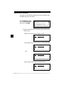
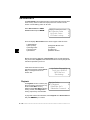
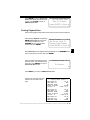
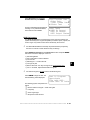
Scan Tool Setup
Tool Setup allows you to change the
measurement units and LCD contrast,
turn beeper On/Off and display tool
information. The settings remain until
the internal batteries become
discharged.
Main Menu
` Vehicle Diagnosis
Tool Setup
Tool Self-Tests
?
[
~
Setup Tool
` 1)English/Metric
2)Display Contrast
3)Beeper
[
~
Measurement Units
To change the measurement units, use
the UP/DOWN arrow keys to select
English/Metric and press ENTER.
In the Measurement Units menu,
select English or Metric and then press
ENTER. English is the default.
Press ENTER again to return to the Setup Tool menu.
Changing Display Contrast
The display contrast can be adjusted
from the Tool Setup menu. Select
Display Contrast and press ENTER.
Use the UP/DOWN arrow keys to
increase and decrease the contrast.
Press ENTER to save the setting and to
return to the Setup Tool menu.
] Increase Contrast
[ Decrease Contrast
Press ENTER To Save ~
Beeper
Beeper selection allows the user to turn Off the tool’s beeper. The bell symbol
~ will not appear in the lower right hand corner of the display when the beeper
is off.
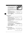
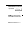
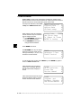
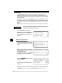
Tool Information
Tool Information:
` Serial No:10000085
SW ID: 945BH
HW Ver: 0
Select Tool Information with the
Boot Ver:
0
UP/DOWN arrow keys and press ENTER.
Prod ID:3
The information shown to the right displays
Board ID:
10
on the screen. Use the UP/DOWN arrow
Burn
Date:03/07/02
keys to view all the lines.
This function allows you to view specific
tool information that may be needed when
contacting customer service.
Press the BACK or ENTER key to return to
the Setup Tool menu.
✓
Write this information in the space provided on the inside of the front cover.
Printer Interface
The scan tool is designed as a Data Terminal Equipment (DTE) device with a
DB9M (9-pin D-shape male) connector to interface with a compatible serial
printer.
••••••••••••••••••••••••••••••••••••••••••••••••••••••••• 3–5
3
Using The Scan Tool
Compatible Printers
The printer must have a serial RS-232 interface circuit and be compatible with
the Epson FX format. The following printers are recommended:
❒
❒
❒
❒
3
Seiko DPU-414
Kodak DICONIX 180si (serial printer model)
Lexmark Model 2480 with optional serial interface (p/n 12T0154)
Panasonic KX-P1131 printer
Cabling
❒ Type: A standard RS-232 type cable.
❒ Scan Tool end: DB9F (female) connector.
❒ Printer end:
• Use a DB9M (male) connector for the Seiko and
DB9
Kodak printers.
• Use a DB25 male connector for the Lexmark and
Panasonic printers.
• If the printer uses a different connector, then an
adapter or different RS-232 cable is required. AdaptDB25
ers are available at most local PC stores or electronics outlets.
Serial Port Settings
❒ Default settings for the scan tool are: 9600 Baud, 8 Data Bits, No Parity
and 1 Stop Bit.
❒ Ensure the settings on the scan tool and printer match.
❒ For the Lexmark and Panasonic printers, ensure the printer’s interface
selection is set to either “auto” or “serial”.
The printer and scan tool must have the same communication settings. You can
change the scan tool’s settings if necessary.
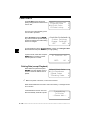
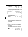
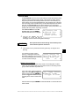
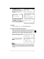
Changing the Printer Settings
Select either Print Codes from the Main
Menu or Print Data from of the
Function List and press ENTER.
Next, the tool will inform you of the
printer settings (Custom or Default),
then ask if you wish to change them.
Select YES and press ENTER.The
default values are designated on the
display with the word (Default) next to
the option.
Main Menu
Vehicle Diagnosis
` Print Codes
Tool Setup
?
[
Tool Set To Default ?
Printer Settings.
Change
Settings?
Yes
<No>
3–6 ••••••••••••••••••••••••••••••••••••••••••••••••••••••••
Using The Scan Tool
Refer to the printer manual for the settings. The changes made reside in the tool
even when the tool is turned off.
Tool settings are as follows. Defaults are in [ . . . ]
❒
❒
❒
❒
Baud Rate: [9,600], 1200, 2400
Stop Bits: [1 Bit], 2 bits
Parity: [None], Odd, Even
Printer Speed: [Fast], Slow
Press ENTER after selecting each setting. Follow the instructions displayed on
the screens. For the printer to work properly, the tool and the printer must be set
to the same configuration. Change the settings accordingly.
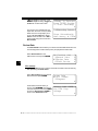
To change the settings,
press the LEFT arrow
and then ENTER.
Use the BACK key to
return to the previous
menu.
The new printer settings
are tested by printing the
ASCII character set.
Press to continue.
Make sure printer is
turned ON, ONLINE and
connected to the tool.
Press the ENTER key to
begin printing.
Select Baud Rate
` 9600(Defalut)
1200
2400
Select Data Bits
` 8 (Default)
[
Select Stop Bits
1 Bit(Default)
` 2 Bits
Select Parity
` None (Default)
Odd
Even
Printer
` Fast (Default)
Slow
The ASCII Character
Set Will Be Printed
Once.
Press
to Itself
Cont.
Test ENTER
Ends By
In Approximately 10
Seconds.
Press ENTER to Cont.
If the printout is not OK, then retry or
change settings. If it is, press ENTER
and the data transmits and prints.
A printout of the test looks similar to the
example shown.
Make Sure Device
Is Turned On, Online
& Connected To Tool.
ENTER To Print
-[ Print Test ]!"#$%&'()*+,-./01234
56789:;<=>?@ABCDEFGH
IJKLMNOPQRSTUVWXYZ[\
]^_`abcdefghijklmnop
qrstuvwxyz{|}~
••••••••••••••••••••••••••••••••••••••••••••••••••••••••• 3–7
3
Using The Scan Tool
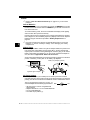
CONNECTING THE SCAN TOOL
To diagnose a vehicle, connect the DLC and
power adapter (if applicable) to the scan tool.
Refer to “Diagnostic Link Connectors (DLC)”
on page 2-5 of Getting Started.
Diagnostic
Connector
If you just want to power up the tool to do its
self-tests, code lookup, review or printing data
from the last vehicle tested, then you do not need
to attach the cable to the Data Link Connector. The internal battery provides
power for this.
3
When the scan tool powers up, a series
of messages display on the screen
beginning with a “Welcome” screen and
ending with a “Key Button Help” screen.
If you wish to review the key button
definitions, push the HELP key;
otherwise, press ENTER to continue.
Welcome To The
Professional
Enhanced Scan Tool
SW ID: XXXX
Vehicle Selection
When the tool powers up, the “Key Button Help” screen is followed by a Main
Menu screen.
Pick Vehicle Diagnosis to begin
Vehicle Selection. If there is a previous
vehicle present, the tool displays that
vehicle. You can choose the last vehicle
selected or setup for a new vehicle. The
tool retains all data retrieved from the
last vehicle selected until any of the
following occurs:
Main Menu
` Vehicle Diagnosis
Tool Setup
Tool Self-Tests
?
[
~
❒
❒
❒
❒
A new vehicle is selected
Internal AAA batteries are depleted or disconnected
Tool is flash programmed to update software
The last vehicle selected is kept but you choose Erase Data
You can either keep the previously
1995 Neon
selected vehicle or change it. If
C=2.0L
SFI SOHC
changing the vehicle, press the RIGHT
arrow key and press ENTER.
Otherwise, press ENTER to keep the
<KEEP>
CHANGE
current one.
Keep Current Vehicle
The next screen asks if you want to
erase the stored data. The default is NO.
After pressing ENTER, the function list
displays.
Erase All Stored
Data For Selected
Vehicle?
YES
<NO>
3–8 ••••••••••••••••••••••••••••••••••••••••••••••••••••••••
Using The Scan Tool
Changing the Vehicle
Changing vehicles erases all data
stored in the tool. The default is YES.
Picking New Vehicle
Erases All Stored
Data. Continue?
<YES>
NO
Press ENTER to continue.
Four Vehicle Options are available: Global OBD II, Domestic Vehicles,
European Vehicles, Asian Vehicles. Global OBD II does not require additional
information and takes you directly to the function list. The other three require
additional information so that the tool can communicate with the vehicle. For
example, select GENERAL MOTORS.
✓
On GM vehicles the tool may require you to look at the VIN to determine the
Series Model, Engine Size, etc.
GM Typical VIN
VIN Position 1 2 3 4 5 6 7 8 9 10 11 12 13 14 15 16 17
Model Year
Engine Type
Chassis Type
Series
Line Chassis
Description of Number
••••••••••••••••••••••••••••••••••••••••••••••••••••••••• 3–9
3
Using The Scan Tool
The menus provide a list
of choices and reference
the vehicle’s VIN where
applicable. The VIN is
visible from outside the
vehicle by looking
through the base of the
front windshield at the top
of the dashboard on the
driver’s side. Because
manufacturers use
different VIN schemes,
the tool will indicate which
digit of the VIN to locate
for information such as
Year, Make and Engine.
3
Use UP/DOWN arrow
keys to move through the
list.
If you make a mistake,
press the BACK key to
return to the previous
menu.
At the last screen, press
ENTER.
Select Vehicle
Global OBDII
` Domestic Vehicle
[
Select Manufacturer
` General Motors
Ford
Select
Vehicle Type [
`Chrysler
Car
Truck
Select Year VIN 10
T=1996
]
` S=1995
[
R=1994
Select Make VIN 3
3=Oldsmobile
]
` 4=Buick
[
6=Cadillac
Select Model
Park Avenue
]
` Regal
[
RevieraEngine VIN 8
Select
` L=3.8L SFI
M=3.1L1995
SFI Regal
4T60E
M=3.1LL=3.8L
SFI AUTO-3S
SFI
<KEEP>
If a message displays, follow the
instructions then press ENTER.
CHANGE
Turn Key Off
For 10 Seconds
Then Turn Key On
Then Press ENTER
3 – 10 • • • • • • • • • • • • • • • • • • • • • • • • • • • • • • • • • • • • • • • • • • • • • • • • • • • • • • •
Using The Scan Tool
User Interface
The scan tool is designed to be as intuitive as possible. All menu and lists
operate the same way. Use the UP/DOWN arrow keys to move UP/DOWN
through the display or move the cursor (`) to a selectable item. Press the
ENTER key to select the function or item. To return to previous screens, press
the BACK key. This information can be viewed on the scan tool by pressing the
HELP key after powering up the scan tool.
If a list or message contains more than four lines, an arrow icon displays on the
last column of the display to indicate the scrolling direction available: up (]) or
down ([). Use the UP/DOWN arrow keys to move line-by-line through the
display. When the bottom of the list is reached, then only the ] displays. At the
top of the list, only the [ displays.
For example: to read DTCs stored in the
vehicle, move the cursor to Read
Codes with the UP/DOWN arrow keys
and press ENTER. To make a different
choice, such as viewing data, use the
UP/DOWN arrow keys to move the
cursor down to View Data and press
ENTER.
Function List
` 3)Erase DTC(Codes)
4)View Data
5)View Freeze Data
?
]
[
~
User Responses
The scan tool may ask a question which
View Instructions
requires a YES or NO response —
For
Creating Custom
brackets (< >) enclose the default one.
Data List?
To accept the default choice, press the
ENTER key. To change the answer,
Yes
<No>
~
press the LEFT/RIGHT arrow keys to
move the brackets to another response and press ENTER.
Viewing Data
Viewing data allows you to observe
sensor data and the operation of
switches, solenoids, and relays. As the
computer monitors the vehicle, the
parameter Identification (PID) data is
transmitted to the scan tool.
Function List
3)Erase DTC(Codes)
` 4)View Data
5)View Freeze Data
?
]
[
~
For viewing options, select View Data from the Function List and press
ENTER.
• • • • • • • • • • • • • • • • • • • • • • • • • • • • • • • • • • • • • • • • • • • • • • • • • • • • • • • • 3 – 11
3
Using The Scan Tool
Entire Data List
The Entire Data List shows all
supported parameter identification
(PID) data for the vehicle being tested.
When the scan tool makes a recording,
the data from all supported PIDs are
stored in the scan tool.
Select Data To View
` Entire Data List
Custom Data List
View Data Setup
~
Custom Data List
The Custom Data List allows you to
select certain PIDs from the Entire Data
List, such as those PIDs that pertain to
a specific driveability symptom or
system. The scan tool asks if you want
to view the instructions.
View Instructions
For Creating Custom
Data List?
YES
<NO>
~
3
Once in the Custom Data List menu,
follow the instructions described below.
A « symbol will be displayed next to all
selected PIDs. Use the UP/DOWN
arrow keys to scroll through the list.
Select Custom List
« MIL STATUS
ABSLT TPS(%)
` ENGINE(RPM)
[
~
Use the UP/DOWN arrow keys to move up and down through the list.
UP arrow: Moves the cursor up the data list.
DOWN arrow: Moves the cursor down the data list.
RIGHT arrow: Selects or deselects a data parameter. All selected data
values are marked with « symbol.
• LEFT arrow: Deselects all marked data parameters.
• ENTER key: Starts playing back data, recording data, or displaying selected
data parameters.
•
•
•
•
Once in the Custom Data List selection screens, follow the instructions
described above to build a Custom Data List. Data parameters or Parameter
Identification Data (PID) will follow in alphabetical order.
When you are done selecting the PIDs, press the ENTER key to view selected
PID values. Press the BACK key twice to return to the Select Data To View
menu.
View Data Setup
View Data Setup changes the number
of lines shown on the screen. Selecting
fewer lines provides faster update
speeds. The default is four-line display.
Select Data To View
Entire Data List
Custom Data List
` View Data Setup
~
3 – 12 • • • • • • • • • • • • • • • • • • • • • • • • • • • • • • • • • • • • • • • • • • • • • • • • • • • • • • •
Section 4 – Global OBDII Diagnostics
The first time scan tool links to the vehicle, communication is automatically
detected, and is used until scan tool is turned OFF or another vehicle is
diagnosed.
✓
If an Error Message displays, make sure OBDII connector is attached,
and ignition key is ON. Cycle ignition key to OFF for 10 seconds, then ON.
This may be required to reset computer. If required, select YES to try
again. If problem still exists, refer to “Error Messages” on page 9-2.
✓
On initial link to vehicle, Scan Tool checks status of I/M Monitors no
matter which function is selected.
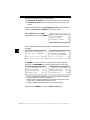
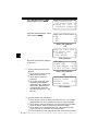
MANUAL INFO
The Manual Info function, tells user what section of manual to use. This section
covers Global OBDII Diagnostics.
I/M READINESS
The I/M Readiness (Inspection and Maintenance) function displays state of
vehicle’s OBD II Monitors. Monitors are tests to verify operation of emission
related systems or components and detect out-of-range values. Vehicle may
have to be operated under certain driving conditions to initiate a monitor. If
vehicle loses electrical power or codes are erased, monitors may be cleared.
This function can be performed with key ON — engine OFF (KOEO) or key ON
— engine Running (KOER).
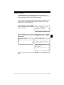
Abbreviations and names for OBDII Monitors supported by Scan Tool are
shown below. They are required by the U.S. Environmental Protection Agency
(EPA). Not all monitors are supported by all vehicles.
Abbreviated Name
Expanded Name
Misfire Monitor ..............................Misfire Monitor
Fuel System Mon .........................Fuel System Monitor
Com Component ..........................Comprehensive Components Monitor
Catalyst Mon ................................Catalyst Monitor
Htd Catalyst..................................Heated Catalyst Monitor
Evap System Mon ........................Evaporative System Monitor
Sec Air System ............................Secondary Air System Monitor
A/C Refrig Mon.............................Air Conditioning Refrigerant Monitor
Oxygen Sens Mon .......................Oxygen Sensor Monitor
Oxygen Sens Htr .........................Oxygen Sensor Heater Monitor
EGR System Mon ........................Exhaust Gas Recirculation System Monitor
••••••••••••••••••••••••••••••••••••••••••••••••••••••••• 4–1
4
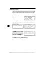
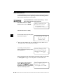
Global OBDII Diagnostics
Vehicles may support two types of I/M Readiness:
❒ SINCE DTCs CLEARED shows monitor status since DTCs were erased.
❒ THIS DRIVING CYCLE shows monitor status since current drive cycle
started.
If monitors are not supported for THIS DRIVING CYCLE, Scan Tool only shows
monitors for SINCE DTCs CLEARED with no header on line 1.
Select I/M Readiness from OBDII
Function List menu and press ENTER.
OBDII Function List ?
1)I/M Readiness
2)Read Codes
[
3)Pending Codes
~
Scan Tool displays message stating whether or not I/M Readiness monitors are
completed.
44
On-Board Readiness ?
Tests Are Complete
Use [ To View Test~
Not All Supported
On-Board Readiness
Tests Are Complete.
Use [ To View
~
Use DOWN arrow key to view monitor statuses. If both monitor types are
supported, use LEFT/RIGHT arrow keys to toggle between monitor types.
THIS DRIVING CYCLE
Misfire Monitor
n/a
Fuel System Mon
ok [
Catalyst Mon
inc ~
SINCE DTCS CLEARED
Misfire Monitor
ok
Fuel System Mon
ok [
Catalyst Mon
inc~
• A status of “OK” means required driving conditions for that monitor have
been met and monitor has ran to completion.
• A status of “Inc” means required driving conditions for that monitor have
not been met or monitor did not complete its cycle.
• A status of “N/A” means vehicle does not support that monitor.
When done, press BACK key to return to OBDII Function List.
4 – 2• • • • • • • • • • • • • • • • • • • • • • • • • • • • • • • • • • • • • • • • • • • • • • • • • • • • • • • • •
Global OBDII Diagnostics
READ CODES
The Read Codes function gets Diagnostic Trouble Codes (DTCs) from
vehicle’s computer module(s). Read Codes function can be done with Key On
Engine Off (KOEO) or Key On Engine Running (KOER).
These codes cause computer to light Malfunction Indicator Lamp (MIL) when
emission-related or driveability fault occurs. MIL is also known as “service
engine soon” or “check engine” lamp.
Select Read Codes and press ENTER.
Scan Tool gets DTCs stored in vehicle’s
computer module(s).
OBDII Function List ?
1)I/M Readiness
` 2)Read Codes
[
3)Pending Codes
~
Scan Tool displays DTCs or a message stating SYSTEM PASS: NO CODES
FOUND. Scroll down to view DTCs or press BACK key to return to OBDII
Function List.
System Pass:
No Faults Detected.
~
DTCs Found: 1
Use [ To View DTCs
Write Down Codes
For Reference
~
P0107 Mod$10 1/1
MAP/BARO
Circuit Low Input
[
~
Write down DTCs for reference and press BACK to return to OBDII Function
List.
••••••••••••••••••••••••••••••••••••••••••••••••••••••••• 4–3
4
Global OBDII Diagnostics
PENDING CODES
Pending Codes are also referred to as “continuous monitor” and “maturing
codes”. An intermittent fault causes computer to store a code in memory. If fault
does not occur within 40 warm-up cycles, code clears from memory. If fault
occurs a specific number of times, code matures into a DTC and MIL lights or
blinks. This function can be done with KOEO or KOER.
Select Pending Codes and press
ENTER key.
OBDII Function List ?
1)I/M Readiness
2)Read Codes
[
` 3)Pending Codes
~
Scan Tool displays Pending DTCs or a message stating SYSTEM PASS: NO
FAULT DETECTED.
44
System Pass:
No Faults Detected.
~
Use DOWN arrow key to view DTCs or
press BACK key to return to OBDII
Function List. If these tests show a
fault, DTCs display in same format as
Read Codes. Use UP/DOWN arrow
keys to view pending DTC(s).
DTCs Found: 2
Use [ To View DTCs
Write Down Codes
For Reference
~
P0115 Mod$10 1/2
Engine Coolant Temp
Circuit Malfunction [
~
Press BACK key to return to OBDII Function List.
4 – 4• • • • • • • • • • • • • • • • • • • • • • • • • • • • • • • • • • • • • • • • • • • • • • • • • • • • • • • • •
Global OBDII Diagnostics
ERASE CODES
The Erase Codes function deletes DTCs from vehicle’s computer memory. It
may also erase Freeze Frame, O2 Sensor Data, System Monitors, and
On-Board Monitor test results. Perform this function only after systems have
been checked completely and DTCs have been documented. This function
should be performed with KOEO — Do not START engine.
After servicing vehicle, erase stored DTCs and verify no codes have been reset.
If DTCs return, problem has not been fixed or other faults are present.
✓
In addition to clearing DTCs, Erase Codes function may also erase
Freeze Frame, O2 Sensor Data, System Monitors, and On-Board Monitor
test results.
Select Erase Codes and press ENTER
key.
Message appears asking if sure. Press
LEFT/RIGHT arrow keys to move
brackets to response and press
ENTER.
4
OBDII Function List
` 4)Erase Codes
5)View Data
6)View Freeze Data
?
]
[
~
Erase Diagnostic
Results and Codes?
Are You Sure?
Yes
<No> ~
Selecting NO displays a COMMAND CANCELLED message prompting to
press ENTER to continue back to OBDII Function List.
Selecting YES displays a screen
prompting to turn ignition KOEO, press
ENTER key to continue.
Command Sent
Press ENTER To Cont~
Scan Tool sends erase command. Press ENTER to continue and return to
OBDII Function List.
••••••••••••••••••••••••••••••••••••••••••••••••••••••••• 4–5
Global OBDII Diagnostics
VIEW DATA
The View Data function allows “real time” viewing of vehicle’s Parameter
Identification (PID) data. As computer monitors vehicle, information is
simultaneously transmitted to scan tool. Apart from Read Codes, View Data is
the most useful diagnostic function for isolating cause of a vehicle operation
problem. Viewing data is also used for observing sensor data and status of
switches, solenoids, and relays.
Select View Data from OBDII Function
List and press ENTER.
Scan tool asks vehicle to provide global
PIDs it supports.
44
OBDII Function List ?
4)Erase Codes
]
` 5)View Data
[
6)View Freeze Data ~
Validating PID Map
PID 23 of 99
Please Wait
After generating PID list, scan tool
displays menu with display options.
Use UP/DOWN to select option and
press ENTER. Refer to “Viewing Data”
on page 3-11 to setup data list.
Select Data To View
` Entire Data List
Custom Data List
View Data Setup
~
After making selection, press ENTER to establish a communication link.
Multiple PIDs may be sent if vehicle is equipped with more than one computer
module — Powertrain Control Module (PCM), Transmission Control Module
(TCM), etc. Scan tool identifies them by their identification names (ID) assigned
by manufacturer (i.e. $40 or $1F).
If Scan Tool receives multiple
responses for a PID, such as MIL
STATUS, Scan Tool displays PID and
with computer module ID blinking in
parentheses.
MIL STATUS($10)
MIL STATUS($1A)
ENGINE($10)
ENGINE($1A)
ON
OFF
256[
261 ~
4 – 6• • • • • • • • • • • • • • • • • • • • • • • • • • • • • • • • • • • • • • • • • • • • • • • • • • • • • • • • •
Global OBDII Diagnostics
If one or more control modules stops
responding, tool displays message that
it is not responding.
Module $1F is not
Responding. Continue
Without it?
Yes
<No> ~
If choosen to continue, dashes will replace data in right-hand column. If NO is
selected, then scan tool attempts to reestablish communication with that
module.
Press FUNC to return to OBDII Function List.
VIEW FREEZE DATA
When an emission-related fault occurs, certain vehicle conditions are recorded
by the on-board computer. This information is referred to as Freeze Frame data.
The information is a “snapshot” of operating conditions at time of fault. This data
can be overwritten by faults with a higher priority.
✓
If codes were erased, then freeze frame data may not be stored in vehicle
memory.
Select View Freeze Data from OBDII
Function List and press ENTER.
Scan tool links to vehicle, and verifies
PIDs and displays data. Use
UP/DOWN arrow keys to move through
list.
If more than one computer module
responds with freeze frame data, then
frame number and module display on
first line of Scan Tool. Press
LEFT/RIGHT key to change modules.
OBDII Function List
?
4)Erase Codes
]
5)View Data
[
` 6)View Freeze Data ~
TROUB CODE
ABSLT TPS(%)
CALC LOAD(%)
COOLANT (oF)
P0443
36.5
95.0[
120~
Frame 1
Mod $1A
TROUB CODE
P044
ABSLT TPS(%)
36.5[
CALC LOAD(%)
95.0~
When done, press BACK key to return to OBDII Function List.
••••••••••••••••••••••••••••••••••••••••••••••••••••••••• 4–7
4
Global OBDII Diagnostics
O2 MONITOR TEST
✓
The O2 Monitor Test is NOT AN ON-DEMAND TEST. O2 sensors are
NOT tested when selected via the menu. O2 sensors are tested when
engine operating conditions are within specified limits.
✓
If vehicle communicates using a Controller Area Network (CAN), O2
Monitor tests are NOT supported by vehicle. A message is displayed.
See Diagnostic Monitor Test to see O2 Monitor data.
OBDII regulations require applicable vehicles monitor and test oxygen (O2)
sensors to determine problems related to fuel and emissions. The O2 Monitor
Test allows retrieval of completed O2 sensors monitor test results.
O2 sensors are located before (upstream) and after (downstream) catalyst(s).
Sensors are named (xy) for their position to both cylinder banks and catalysts.
44
• The O2 sensor for cylinder bank 1 has prefix 1y while O2 sensor for cylinder
bank 2 has prefix 2y.
• The O2 sensor upstream of catalyst (closest to engine) has suffix x1 while
O2 sensor downstream of catalyst has suffix x2. If vehicle contains more
catalysts, O2 sensor downstream of second catalyst has suffix x3 and O2
sensor downstream of next catalyst has suffix x4.
• For example, O2S21 is upstream O2 sensor for cylinder bank 2.
The following O2 sensor tests are available:
1) Rich to Lean sensor threshold voltage
2) Lean to Rich sensor threshold voltage
3) Low sensor voltage for switch time
4) High sensor voltage for switch time
5) Rich to Lean sensor switch time
6) Lean to Rich sensor switch time
7) Minimum sensor voltage test cycle
8) Maximum sensor voltage test cycle
9) Time between sensor transitions
10) Sensor Period
Select O2 Monitor Test from OBDII
Function List and press ENTER.
OBDII Function List
` 7)O2 Monitor Test
8)Diag Mon Test
9)On-Board Systems
?
]
[
~
4 – 8• • • • • • • • • • • • • • • • • • • • • • • • • • • • • • • • • • • • • • • • • • • • • • • • • • • • • • • • •
Global OBDII Diagnostics
Select Oxygen Sensor information to
view.
Select O2 Sensor
` 02 BANK1 Sensor1
~
✓
The O2 sensors located upstream (before catalyst) may perform
differently than ones located downstream (after catalyst).
View test information by using UP and
DOWN arrows.
02 Bank1 Sensor1
RICH-LN Thresh
0.450(V)
MOD$10 [
~
4
Press BACK key to return to O2 Sensor Tests menu or press FUNC to return
to OBDII Function List.
DIAGNOSTIC MONITOR TESTS
The Diagnostic Monitor Test function is useful after servicing or after erasing
vehicle’s memory. Test results do not necessarily indicate a faulty component
or system.
Non-CAN vehicles Diagnostic Monitor Tests receives test results for
emission-related powertrain components and systems not continuously
monitored.
CAN vehicles Diagnostic Monitor Tests receives test results for
emission-related powertrain components and systems that are or are not
continuously monitored.
✓
Vehicle manufacturer is responsible for assigning test and component IDs.
••••••••••••••••••••••••••••••••••••••••••••••••••••••••• 4–9
Global OBDII Diagnostics
Select Diag Mon Test from OBDII
Function List and press ENTER.
Applicable tests are displayed . Select
a test and press ENTER.
OBDII Function List
7)O2 Monitor Test
` 8)Diag Mon Test
9)On-Board Systems
?
]
[
~
Diag Mon Data Avail
` $01
$05
[
$10
~
Non-CAN Vehicles
OR
Diag Mon Data Avail
` O2 Sensor B1S1
Catalyst B1
[
EVAP (0.090)
~
44
CAN Vehicles
Requested test results are displayed
on Scan Tool
✓
On Non-CAN vehicles Scan Tool
displays:
❒ On the 1st line is where the test
❒
❒
✓
data (test ID) came from.
On the 2nd line is the test
performed
On the 3rd and 4th line is the
test measurement (MEAS),
specification value (SPEC) and
status (STS). Measurements
and Specification values are
hexadecimal numbers (i.e., $1A,
$FE, $11.)
TEST $01
ID MEAS SPEC
STS
74 8861 C000min
Low [
76 3876 FFFFmax OK~
Non-CAN Vehicles
OR
O2 Sensor B1S1($00) ?
RICH-LN Thresh
0.5629(V)
OK [
{O.5629, 0.5629}
CAN Vehicles
On CAN vehicles Scan Tool displays:
❒ On the 1st line is where the monitor test data came from. For example
($00)represents the source module id from where the data originated.
❒ On the 2nd line is the test performed. The test performed can be $## if
test is not defined. Refer to vehicle service manual for details.
❒ On the 3rd line are the measured value and units measured in (Volts,
Amps, Seconds, etc.) and status of monitor test data.
❒ On the 4th line the low and high limits are shown for the monitor test data.
4 – 10 • • • • • • • • • • • • • • • • • • • • • • • • • • • • • • • • • • • • • • • • • • • • • • • • • • • • • • • •
Global OBDII Diagnostics
If additional tests are present use UP/DOWN arrow keys to view test results.
Refer to appropriate vehicle service manual for test IDs and definitions.
Press BACK key to return to the Diag Mon Test menu or press FUNC key to
return to OBDII Function List.
ON-BOARD SYSTEMS
The On-Board Systems test allows scan tool to control operation of vehicle
components, tests or systems. Some manufacturers do not allow tools to
control vehicle systems. A vehicle not supporting an on-board system is
identified by a message displayed when selected.
4
✓
Refer to vehicle service manual for on-board systems instructions.
Select On-Board Systems from
OBDII Function List and press
ENTER.
OBDII Function List
` 10)Record Data
11)Vehicle Info
12)Modules Present
?
]
[
~
A list of on-board systems and components available for testing display on
screen.
Select a test and press ENTER to activate test. Manufacturer is responsible for
determining criteria to automatically stop test. Refer to appropriate vehicle
service manual.
• • • • • • • • • • • • • • • • • • • • • • • • • • • • • • • • • • • • • • • • • • • • • • • • • • • • • • • • 4 – 11
Global OBDII Diagnostics
RECORD DATA
The Record Data function records PIDs while vehicle is parked or being driven.
This function is mainly used for diagnosing intermittent driveability problems
that cannot be isolated by any other method.
Two people MUST be in vehicle when driving — one to
drive and the other to operate scan tool.
Select Record Data from OBDII
Function List and press ENTER.
OBDII Function List
` 10)Record Data
11)Vehicle Info
12)Modules Present
?
]
[
~
Follow all instructions on display.
44
Scan tool asks vehicle to provide global
PIDs vehicle supports.
Validating PID Map
PID 23 of 99
Please Wait
✓
Scan tool can maintain only one recording per group. Make sure to
thoroughly review old recording before erasing.
If a recording currently exists in
memory, a message prompting to erase
data is displayed.
Cannot Record. Old
Recording Filled Up
Memory. Erase Old?
YES
<No>
~
After list is generated, scan tool prompts to select type of data to record. Refer
to “Viewing Data” on page 3-11 to setup Entire or Custom Data Lists.
On next screen, select a triggering
method. Manual Trigger allows
technician to use ENTER key. Trigger
On Codes automatically triggers when
a DTC is indicated by vehicle.
Pick Trigger Method
`1)Manual Trigger
2)Trigger On Codes
4 – 12 • • • • • • • • • • • • • • • • • • • • • • • • • • • • • • • • • • • • • • • • • • • • • • • • • • • • • • • •
Global OBDII Diagnostics
Once trigger method is selected, scan tool will begin recording data. When
trigger event (either a DTC or a Press of ENTER key) occurs, time is recorded
and data from last five frames are saved. Data will continue to be saved until
either record memory is full or technician presses ENTER.
** INITIALIZING **
PRETRIG FRAME:-5
BACK To Exit
~
Press BACK key twice to return to
OBDII Function List.
✓
**Ready To Record**
Press ENTER Anytime
To Start Recording.
Stops Automatically~
Waiting For Trouble
Code To Trigger The
Start of Recording
BACK To Exit
~
Scan tool can maintain only one recording at a time. Make sure to
thoroughly review old recording before erasing.
Scan tool recording time varies. A
recording consists of 5 frames of data
prior to trigger and several frames after
trigger. The amount of PIDs recorded
determine number of frames.
After recording, Scan Tool displays a
prompt to playback recording. Answer
NO to return to OBDII Function List.
4
**Recording Data*
FRAME: 14 of 29
Press ENTER to Stop ~
Playback Data?
<YES>
NO
~
Answer YES to display recorded data. Refer to “Playback” on page 4-18 for
description of function.
• • • • • • • • • • • • • • • • • • • • • • • • • • • • • • • • • • • • • • • • • • • • • • • • • • • • • • • • 4 – 13
Global OBDII Diagnostics
VEHICLE INFO
The Vehicle Info function allows scan tool to request vehicle’s VIN
number, calibration ID(s) which identifies software version in vehicle
control module(s), Calibration Verification Numbers (CVN(s)) and
In-Use Performance tracking.
44
✓
Vehicle Info function applies to model year 2000 and newer OBD II
compliant vehicles.
✓
✓
The Scan Tool cannot verify if data is correct for scanned vehicles.
✓
✓
The CVN calculation may take several minutes.
✓
In-Use Performance Tracking, tracks performance of key Readiness
Monitors.
✓
The calculation may take several minutes first time CVNs are requested.
Calibration Verification Numbers (CVNs) are calculated values
required by OBD II regulations.
CVNs are reported to determine if emission-related calibrations have
been changed. Multiple CVNs may be reported for a control module.
Select Vehicle Info from OBDII
Function List and press ENTER.
Scan Tool displays VIN, Calibration ID,
and CVNs if supported by vehicle. In
following examples, Module 10
returned data. Scroll down to view
information. CVNs are shown as
hexadecimal number.
Cal ID # 1 MOD $10
GXAG20w.HEX
?
]
[
~
OBDII Function List
10)Record Data
` 11)Vehicle Info
12)Modules Present
?
]
[
~
VIN # 1 MOD $10
1F1FS11P0S2100001
?
[
~
Cal Ver # 1 MOD $10
D4 5B 01 5D
?
]
~
4 – 14 • • • • • • • • • • • • • • • • • • • • • • • • • • • • • • • • • • • • • • • • • • • • • • • • • • • • • • • •
Global OBDII Diagnostics
Scan Tool displays in-use performance
tracking data, if supported by vehicle. In
following examples, Module 10 returned
data. Scroll down to view information.
IPT Counts MOD $10 ?
OBDCOND(cnts)
2
IGNCNTR(cnts)
22
CATCOMP1(cnts)
35~
Abbreviations and names for In-Use Performance Tracking Data supported by
Scan Tool are shown below. Not all data is supported by all vehicles.
Abbrieviated Name
IPT
OBDCOND
IGNCNTR
CATCOMPx
CATCONDx
O2SCOMPx
O2SCONDx
EGRCOMP
EGRCOND
AIRCOMP
AIRCOND
EVAPCOMP
EVAPCOND
Expanded Name
In-use Performance Tracking
OBD Monitoring Conditions Encountered Counts
Ignition Counter
Catalyst Monitor Completion Counts Bank x
Catalyst Monitor Conditions Encountered Counts Bank x
O2 Sensor Monitor Completion Counts Bank x
O2 Sensor Monitor Conditions Encountered Counts Bank x
EGR Monitor Completion Condition Counts
EGR Monitor Conditions Encountered Counts
AIR Monitor Completion Condition Counts (Secondary Air)
AIR Monitor Conditions Encountered Counts (Secondary Air)
EVAP Monitor Completion Condition Counts
EVAP Monitor Conditions Encountered Counts
If message INVALID displays on screen, then data returned is incorrect, or not
formatted in accordance with OBDII specification. Press BACK or ENTER key
to return to OBDII Function List.
• • • • • • • • • • • • • • • • • • • • • • • • • • • • • • • • • • • • • • • • • • • • • • • • • • • • • • • • 4 – 15
4
Global OBDII Diagnostics
MODULES PRESENT
The Scan Tool identifies the module IDs and communication type
for OBDII modules in the vehicle.
Select Modules Present
from the OBDII Function
List and press ENTER.
OBDII Function List ?
10)Record Data
]
1 1)Vehicle Info
[
` 12)Modules Present
✓ Types of Protocols (communication types) supported by
Scan tool are:
•ISO 9141-2 protocol will be shown as ISO
44
ID
Protocols
$41 ISO*
$40 ISO*
•SAE J1850 protocol will be shown as VPWM OR PWM
ID
$10
Protocols
VPWM*
ID
$10
Protocols
PWM*
OR
•ISO 15765-4 protocol will be shown as CAN.
ID
Protocols
$01 CAN*7e9
$00 CAN*7e8
4 – 16 • • • • • • • • • • • • • • • • • • • • • • • • • • • • • • • • • • • • • • • • • • • • • • • • • • • • • • • •
Global OBDII Diagnostics
NOTE: Since CAN vehicles use module ID’s larger
than 2 digits, the Scan Tool will assign a 2 digit module
ID to be used in place of the actual CAN module ID.
The Module ID assigned for the CAN Module ID will be
used in all functions of Scan Tool.
•ISO 14230-4 protocol will be shown as K2K (Keyword
2000.)
ID
$10
$1A
Protocols
K2K*
K2K*
4
• • • • • • • • • • • • • • • • • • • • • • • • • • • • • • • • • • • • • • • • • • • • • • • • • • • • • • • • 4 – 17
Global OBDII Diagnostics
REVIEW DATA
The Review Data function allows operator to review information stored in Scan
Tool’s memory. Scan tool does not require power from vehicle to do this
function. Internal battery power can be used.
Select Review Data from OBDII
Function List and press ENTER.
OBDII Function List
` 13)Review Data
14)Print Data
15)Code Lookup
?
]
[
~
Scan tool displays Review Data screen with nine types of data to review.
44
1) I/M Readiness
2) DTC (Codes)
3) Pending Codes
4) Freeze Frame
5) O2 Monitor
6) Diagnostic Monitor Test
7) Playback
8) Vehicle Info
9) Modules Present
Most of the functions displayed on Review Data screen are self explanatory.
Only one function, Playback, needs detailed instructions. Follow prompts and
instructions provided by scan tool.
If data does not exist for function
selected to review (for example Vehicle
Info), a message informs to run
function first.
Playback
The Playback function is used to play
back a recording. This function is very
similar to View Data. The only
difference is that View Data is real time
viewing of PIDs, while Playback is a
viewing of previously recorded PIDs.
No Data Stored In
Tool. Use VEHICLE
INFO Before
Reviewing.
~
Review Data
`7)Playback
8)Vehicle Info
9)Modules Present
]
~
To play back vehicle’s recorded PIDs, select Playback from Review Data list
and press ENTER key to continue.
4 – 18 • • • • • • • • • • • • • • • • • • • • • • • • • • • • • • • • • • • • • • • • • • • • • • • • • • • • • • • •
Global OBDII Diagnostics
Scan tool displays a NO RECORDING PRESENT message if recording does
not exist. Otherwise, press ENTER to play back recording. Scan tool plays back
Entire Data List or Custom Data List, depending on how data was recorded.
The Playback has three lines of data
and one line for frame number and
timestamp (in seconds).
MIL STATUS($10)
MIL STATUS($1A)
ABSLT TPS(%)($10)
FRAME: 1 TM: 4.4
ON
ON
35[
~
Negative frames and timestamps indicate data recorded before trigger event.
Positive frames and timestamps indicate data recorded after trigger event.
Use UP/DOWN arrow keys to view recorded PID data of each frame. The end
of list is reached when only ] (up) icon is visible.
Use LEFT/RIGHT arrow keys to scroll back and forth through frames. The
RIGHT arrow key goes to next frame, “wrapping around” to earliest frame when
final frame is reached, LEFT arrow key goes back to previous frame, again
“wrapping around” to final frame.
✓
Different vehicles communicate at different speeds and support a different
number of PIDs. Therefore, maximum number of frames that can be
recorded will vary.
✓
Some vehicles wait a long period of time to store a trouble code after
driveability problem occurs. If operator selected “Trigger On Codes” when
making recording, operator might not see any drastic change in data
parameters before and after trigger point. In cases like this, user can
manually trigger recording when symptoms are observed.
When done, press BACK to return to Review Data or OBDII Function List.
• • • • • • • • • • • • • • • • • • • • • • • • • • • • • • • • • • • • • • • • • • • • • • • • • • • • • • • • 4 – 19
4
Global OBDII Diagnostics
PRINT DATA
The Print Data function allows the
printing of diagnostic information stored
in Scan Tool.
OBDII Function List
13)Review Data
` 14)Print Data
15)Code Lookup
?
]
[
~
The scan tool’s internal battery power
can be used to print data.
Select Print Data and press ENTER
key. Scan tool informs of printer settings
(Custom or Default), then asks if setting
need to be changed.
44
Tool Set To Default ?
Printer Settings.
Change Settings?
YES
<NO>
~
To change settings, refer to “Printer Interface” on page 3-5 of Using The Scan
Tool. Select NO and press ENTER key to begin printing.
If printout is OK, select YES and press
ENTER. Refer to settings in printer
manual if printout is not OK.
Is Printout OK?
<YES>
NO
~
Printing Data (except Playback)
Select data to be printed and press
ENTER. Scan tool displays menu of
functions that store data and can be
printed.
✓
Select Print Data
` 1)I/M Readiness
2)Read Codes
3)Pending Codes
[
~
Make sure printer is turned on, on-line and connected.
When selected data does not exist in scan tool’s memory, a message informs
to run function.
If selected data is stored in scan tool,
data automatically transmits to printer.
Transmitting
To Printer
--Please Wait-~
4 – 20 • • • • • • • • • • • • • • • • • • • • • • • • • • • • • • • • • • • • • • • • • • • • • • • • • • • • • • • •
Global OBDII Diagnostics
Press ENTER to return to Select Print
Data screen. Either select another item
to print or press BACK to return to
OBDII Function List
All Data Has Been
Sent To Printer
Press ENTER To Cont. ~
Printing Playback Data
When printing playback data, Start Frame and End Frame need to be defined.
After selecting Playback and pressing
ENTER, Start Frame screen shows
the earliest possible frame. Use
UP/DOWN arrow to change frame
number and press ENTER.
Start Frame:
-5
Use Arrow Keys To
Change Frame Number
Press ENTER to Cont. ~
Next, End Frame screen displays latest possible frame. Use UP/DOWN arrow
keys to change frame number and press ENTER.
Scan Tool starts transmitting to printer,
frame-by-frame. After all frames have
been sent, press ENTER to return to
Select Print Data screen.
Sending Frame -2
To Printer
~
Press BACK key to return to OBDII Function List.
A printout of recording might look
similar to the one shown on the
right.
---(Recorded Data)--BATTERY(V)
COOLANT(F)
ENGINE RPM
LOOP STATUS
Frame:-1
12.0
80
0
OPEN
Time:-1.1
BATTERY(V)
COOLANT(F)
ENGINE RPM
LOOP STATUS
Frame: 0
16.0
90
1000
CLSD
Time:0.0
BATTERY(V)
COOLANT(F)
ENGINE RPM
16.0
90
1000
• • • • • • • • • • • • • • • • • • • • • • • • • • • • • • • • • • • • • • • • • • • • • • • • • • • • • • • • 4 – 21
4
Global OBDII Diagnostics
CODE LOOKUP
Code Lookup is used to look up definitions of Diagnostic Trouble Codes
(DTCs) stored in Scan Tool. Scan tool does not require power from vehicle to
perform this function, the internal battery power can be used.
To look up DTC definitions, select Code
Lookup from OBDII Function List.
When entering codes, all characters
must be entered. Only one character
can be changed at a time.
❒ Use LEFT/RIGHT arrow keys to
scroll to desired character.
OBDII Function List
13)Review Data
14)Print Data
15)Code Lookup
?
]
[
~
Lookup Code:
P0000
Use Arrow Keys
^
To Select Or Press
ENTER To Lookup
~
❒ Use UP/DOWN arrow keys to
change selected character.
44
Press ENTER when done.
Use UP/DOWN arrow keys to display
previous or next DTC. DTCs for the
code type selected (i.e., P, B, C, or U)
are listed in numerical order.
P0622
Generator F-Term.
Field F Control
]
[
~
To enter another DTC number, press BACK key. Press BACK key again to
return to OBDII Function List.
If DTC definition does not exist for
vehicle, then a message, NO DTC
DEFINITION FOUND, displays on
screen.
If DTC is manufacturer specific, DTC is
assigned to display. Refer to vehicle
service manual for exact definition.
P1C95
No DTC Definition
Found. See
Service Manual
]
[
~
P1605
Computer and
Auxiliary Outputs.
See Service Manual
]
[
~
4 – 22 • • • • • • • • • • • • • • • • • • • • • • • • • • • • • • • • • • • • • • • • • • • • • • • • • • • • • • • •
Section 5 – GM Diagnostics
✓
If the Scan Tool displays an Error Message, make sure the cables and
adapters are securely attached and the ignition key is ON. Cycle the
ignition key to OFF for 10 seconds, then ON. Attempt the test selected
again. If the problem remains, refer to “Error Messages” on page 9-2.
GM HISTORIC (OBD I) DIAGNOSTICS
✓
Some 1994 and 1995 vehicles use the 16-pin OBD II connector, but are not
OBD II compliant. They still use the OBD I application software. Refer to
“Appendix A - Data Link Connectors".
Manual Info
The Manual Info function instructs the user what section of the manual to use.
This section covers GM Historic (OBD I) Diagnostics.
Read Codes
The Read Codes function is used to retrieve all stored Diagnostic Trouble
Codes (DTCs) from the control module(s). This can be performed with key ON
engine OFF (KOEO) or key ON engine RUNNING (KOER). Two types of codes
were used by GM in the Historic System: Current codes and History codes.
Prior to 1986, all codes were referred as Current Codes. From 1986 through
1995, both codes were used as the PCM was able to differentiate them.
The tool automatically displays the type of codes that pertain to the vehicle
under test. The DTC types are defined as follows:
• History Codes — intermittent codes placed in the vehicle’s memory when
the trouble originally occurred, and will remain there even if the trouble has
been corrected. If no trouble after 50 engine warm-up cycles, the DTC
erases.
• Current Codes — codes transmitted through the PCM’s data stream when
a trouble condition is active and cannot be erased. The problem must be
repaired to remove the DTC.
✓
On some vehicles, all codes are Current Codes, because the PCM cannot
distinguish Current Codes from History Codes. The only way to determine
this is to erase the code and then drive the vehicle to see if the code
returns.
Perform the following:
1) Set Parking Brake
2) Turn Key On-Engine Off or Running.
3) Put Transmission In Park Or Neutral.
••••••••••••••••••••••••••••••••••••••••••••••••••••••••• 5–1
5
GM Historic (OBD I) Diagnostics
Select Read Codes from the GM
Function List and press ENTER. The
tool will retrieve the DTCs.
GM Function List
` 1)Read Codes
2)Erase Codes
3)View Data
?
[
~
One of two screens displays: If the diagnostic checks are working correctly and
no DTCs have been stored in vehicle’s memory, a SYSTEM PASS message
displays. If not, the tool displays a screen indicating the number DTCs.
System Pass:
No Faults Detected.
~
Use the UP/DOWN arrow keys to scroll
through the codes. Note the codes and
press FUNC to return to the GM
Function List.
5
Codes Found: 1
Use Q To View Codes
Write Down Codes
For Reference
~
Current Code P0325
Ign System Problem
Elec Spark Control
ESC Failure
~
Erase Codes
The Erase Codes function deletes the DTCs from the vehicle’s computer
memory. Perform this function with KOEO or KOER. This function should be
performed only after the systems have been checked completely and DTCs
have been documented.
After servicing the vehicle, erase the stored DTCs, perform a road test, and then
verify no new codes have been stored. If DTCs return, the problem has not been
corrected or other faults are present.
✓
✓
Some codes can only be removed by repairing the faults that caused
them. Therefore, these codes will remain in the vehicle’s memory until the
condition is repaired.
Not all trouble codes can be automatically erased using the scan tool.
Some vehicles require a manual erasing procedure. If possible, the tool
performs the appropriate Erase Codes procedure for your vehicle.
Select Erase Codes and press the
ENTER key.
GM Function List
1)Read Codes
` 2)Erase Codes
3)View Data
?
[
~
5–2 ••••••••••••••••••••••••••••••••••••••••••••••••••••••••
GM Historic (OBD I) Diagnostics
A message appears asking if you are
sure. Press LEFT/RIGHT to move the
brackets to the desired response and
press ENTER.
Erase Codes?
Are You Sure?
Yes
<No>
Selecting NO and pressing ENTER
returns you to the GM Function List.
Selecting YES displays a screen
prompting you to turn ignition ON. Turn
ignition key ON. Engine can be off or
running. Press ENTER to continue.
A message confirming that the Erase
Codes command was successful
displays. Press ENTER to return to
theGM Function List.
Turn Ign Key On
Engine Can Be Off
Or Running.
Press ENTER To Cont
Erase Codes Command
Sent. Perform READ
CODES Function To
Verify Erase.
Manual Erase Methods
Alternate Method 1:
1) Turn Ignition Key Off.
2) Locate Fuse Box and Remove ECM Fuse.
3) Wait 20 seconds.
4) Replace the Fuse.
Alternate Method 2:
1) Turn Ignition Key Off.
2) Remove Power from Scan Tool.
3) Disconnect Scan Tool from Vehicle.
4) Remove Negative (-) Battery Cable. Wait 30 seconds, then replace the
cable.
✓
The computer has a “learning” ability to compensate for minor variations
in engine operation. Whenever power is removed from the PCM, the
computer must “relearn” various functions. Vehicle performance may be
noticeably different until this is accomplished. This is a temporary situation
and is normal. The “learning” process takes place during warm engine
driving.
••••••••••••••••••••••••••••••••••••••••••••••••••••••••• 5–3
5
GM Historic (OBD I) Diagnostics
View Data
The View Data function allows the user to view the vehicle Parameter
Identification Data (PIDs) in real time. As the PCM monitors PIDs, they are
simultaneously transmitted to the scan tool. The PIDs are continuously updated
at the PCM’s rate.
In addition to reading codes, View Data is the most useful diagnostic function
for isolating the cause of a vehicle operation problem. Viewing data is also used
for observing sensor data and the ON/OFF state of switches, solenoids, and
relays.
View Data can be performed with the ignition key On-Engine Off or Running.
!! WARNING
WARNING
Never operate the tool while driving. Have another person
assist with the operation of the tool.
Select View Data from the GM
Function List and press ENTER. If a
Select Group screen does not appear,
skip the Multiple Group section and
continue.
5
GM Function List
1)Read Codes
2)Erase Codes
` 3)View Data
?
Select Group
Engine Group 1
Engine Group 2
` Engine Group 3
?
[
~
Multiple Group Vehicles
Some vehicles display a Select Group
screen for viewing data. In these cases,
only one group of data can be viewed at
a time.
Select the type of data to view. Refer to
“Viewing Data” on page 3-11 for Entire
or Custom Data Lists.
After making a selection, press ENTER
to establish a communication link.
Use the UP/DOWN arrow keys to scroll
through the PIDs.
A Vehicle Data List header marks the
beginning.
~
Select Data To View?
1)Entire Data List
` 2)Custom Data List
~
Custom Data List
Codes Present
Yes
1ST GEAR SW
ON [
A/F RATIO
18.8~
Change the selection of Custom Data List parameters at any time by pressing
the BACK key. This returns to the Custom Data List selection screen.
5–4 ••••••••••••••••••••••••••••••••••••••••••••••••••••••••
GM Historic (OBD I) Diagnostics
Record Data
The Record Data function records vehicle PIDs (Parameter Identification Data)
while the vehicle is parked or being driven. This function is mainly used for
diagnosing intermittent driveability problems that cannot be isolated by any
other method. The tool records data based on time (5 frames prior to the start
of the recording, and for a duration after). The time after depends on the vehicle
data rate. The Record Data function allows diagnosis of an intermittent
problem by analyzing data leading up to the problem, during the problem, and
possibly after the problem, depending on duration.
Select Record Data from the GM
Function List and press ENTER.
Follow all instructions on the display.
✓
The tool can maintain only one
recording at a time. Be sure to
thoroughly review the old recording before erasing it.
!! WARNING
WARNING
✓
GM Function List
` 4)Record Data
5)Review Data
6)Field Service
?
]
[
~
Never operate the tool while driving. Have another person
assist with the operation of the tool.
This function can be performed with the ignition key On-Engine Off or
Running.
If a recording currently exists in
memory, a message to Erase Old
Recording is displayed. The tool stores
only one recording at a time, so be sure
to review it before erasing it.
Cannot Record. Old
Recording Filled Up
Memory. Erase Old?
<YES>
NO
~
Multiple Group Vehicles
Some vehicles display a Select Group screen for recording data. In these
cases, only one group of data can be recorded at a time. Recording another
group of data overwrites the present one.
In the next screen, select a method to
trigger a recording. Manual Trigger will
begin recording when the ENTER key
pressed. Trigger On Codes will begin
recording when a DTC is stored in the
PCM.
Pick Trigger Method
` 1)Manual Trigger
2)Trigger On Codes
~
Select a method and press ENTER. The tool will establish a communication link
with the PCM.
••••••••••••••••••••••••••••••••••••••••••••••••••••••••• 5–5
5
GM Historic (OBD I) Diagnostics
If Manual Trigger is selected, press
ENTER to begin recording. Trigger On
Codes will not show this screen.
The function runs automatically and
stops when the tool’s memory is filled.
When done, the tool prompts you to
“PLAY THE RECORDING?” Select
YES to review the data now or NO to
review it later using the next function,
Review Data.
**Ready To Record**
Press ENTER Anytime
To Start Recording.
~
**Recording Data**
Stops Automatically
When Memory is Full.~
Review Data
The Review Data function allows you to review recorded data stored in the tool
such as Diagnostic Trouble Codes (DTCs) and playback recorded data.
Select Review Data from the
GM Function List and press ENTER.
5
GM Function List
4)Record Data
` 5)Review Data
6)Field Service
?
]
[
~
DTC (Codes)
The DTC (Codes) function is used to review DTCs stored in the tools memory
after performing the Read Codes.
Select DTC (Codes) from the Review
Data screen and press ENTER.
Review Data
` 1)DTC (Codes)
2)Playback
?
~
Codes will be noted as History or
Current. Use UP/DOWN arrow keys if
more than one DTC exists. Press BACK
to return to Review Data or FUNC to
return to the GM Function List.
History Code P0054
Low Fuel Pump
Voltage
~
5–6 ••••••••••••••••••••••••••••••••••••••••••••••••••••••••
GM Historic (OBD I) Diagnostics
Playback
The Playback function is used to playback a Record Data recording. This
function is very similar to View Data. The only difference is that View Data is
a real time viewing of PIDs, while Playback is a viewing of previously recorded
PIDs.
Select Playback from the Review Data
screen and press ENTER:
Review Data
1)DTC (Codes)
` 2)Playback
?
~
✓
If a recording does not exist in the tool memory, then the tool will display
a “NO RECORDING PRESENT” message. Perform “Record Data” on
page 5-5.
Select which list to playback. Refer to
“Viewing Data” on page 3-11 of Using
The Scan Tool for Entire or Custom
Data Lists.
Playback Data As
?
1)Entire Data List
` 2)Custom Data List
~
The Playback screen has a Vehicle
Data List header to mark the beginning of the data list. The recorded PIDs are
displayed next. Line 4 displays the Frame number and Time in seconds.
• Use the UP/DOWN arrow keys to
Vehicle Data List
?
scroll through the data line by line.
CODES PRESENT
YES
The end of the list is reached when
the DOWN arrow icon is not visible.
CALC LOAD(%)
7.0[
• The LEFT/RIGHT arrow keys are
FRAME:
1
Time:
4.4
~
used to increase or decrease the
Frame/Time index. Time 0.0 is the
trigger point, when the user pressed ENTER. A time interval with a minus
sign (–) occurs before the trigger point.
• The tool recording time varies. A recording consists of 5 frames of data prior
to the trigger and several frames after the trigger. The number of PIDs
recorded will determine the number of frames.
✓
✓
✓
After reaching the last time interval recorded. The Time display will
change from data recorded after trigger to data recorded before. This is
normal. The LEFT/RIGHT arrows may be used to scroll through all time
intervals in either direction.
Some vehicles will wait 3 to 4 minutes after the driveability problem first
occurs before storing a trouble code in the vehicle’s on-board computer.
If you selected Trigger On Codes when you made your recording, you
might not see any drastic change in data parameters before and after the
trigger point. In cases like this, it is better to manually trigger the start of
the recording when the driveability symptom is first observed.
To change the selections of Custom Data List parameters, press the
BACK key. This will return to the Custom Data List selection display
screens. When done, press BACK to return to Review Data or FUNC to
return to the GM Function List.
••••••••••••••••••••••••••••••••••••••••••••••••••••••••• 5–7
5
GM Historic (OBD I) Diagnostics
Field Service
Field Service is a special diagnostic mode to monitor fuel system operation and
read DTCs. Some GM service manuals may refer to this mode as the Field
Service Mode Check. This mode works on vehicles equipped with a 12-pin
ALDL connector with a wire present in Pin-B, Diagnostic or Test Enable. The
scan tool enters this mode by grounding Pin-B: shorting Pin-B to Pin -A
(ground).
Field Service Mode can be operated with the ignition Key On-Engine Off
(KOEO) or with the Key On-Engine Running (KOER).
✓
✓
Vehicles equipped with climate control computers do not use Field Service
Mode.
Some 1994 & 1995 vehicles equipped with a 12-pin ALDL connector with
pins A and B shorted will not cause the CHECK ENGINE light to flash
codes.
Select Field Service from the GM
Function List and press ENTER.
5
Turn ignition Key On, but do not start
engine. The Check Engine light should
flash. Select YES to continue. If the light
does not illuminate, either the vehicle
does not support this test mode, the
lamp is burned-out or circuit problems
exist.
✓
GM Function List
4)Record Data
5)Review Data
` 6)Field Service
?
]
[
~
*Test Availability*
Does Your CHECK
ENGINE Light Flash?
<Yes>
No
~
It is difficult to know exactly which GM vehicles use the Field Service
mode. It is possible to have the Field Service mode function on the
Function List, and it not be applicable.
If Check Engine light operates, the Field
Service screen is displayed. Pressing
ENTER will toggle the short to Pins A &
B On and Off.
Field Service: Off ?
Press ENTER To Turn
Field Service On
~
Continue with either the KOEO
procedure or KOER procedure. When done, press FUNC to return to the GM
Function List.
✓
While in Field Service mode, no new trouble codes are stored in the
vehicle’s memory.
5–8 ••••••••••••••••••••••••••••••••••••••••••••••••••••••••
GM Historic (OBD I) Diagnostics
KOEO Procedure
In the KOEO Procedure, Field Service can check relays, solenoids and the idle
speed motor, and obtain DTCs using the CHECK ENGINE light.
1) Turn ignition Key ON but DO NOT Start Engine.
2) On scan tool, place Field Service On.
3) The Check Engine light will begin to flash codes. Each DTC is displayed
three (3) times. The DTCs are displayed starting with the lowest numbered
one. After all DTCs are displayed, the sequence keeps repeating until the
ignition key or Field Service mode is turned OFF.
— Count CHECK ENGINE Light Flashes to obtain trouble codes. The first
digit is sent first. A short pause separates digits while a long pause
separates each DTC. All codes contain 2 digits.
— DTC 12 (No RPM reference pulse) should display first since the engine
is not running. If not, problems exist in the PCM or Check Engine light
circuitry.
Code 12 will look like:
FLASH-pause-FLASH-FLASH — long pause.
Code 23 will look like:
FLASH-FLASH-pause-FLASH-FLASH-FLASH — long pause.
4) When Field Service Mode is ON, most computer controlled Relays and
Solenoids will be turned ON, except for the fuel pump relay and fuel
injectors. Toggle the Field Service Mode On and Off.
❒ Use a voltmeter to measure Relays and Solenoids input voltage to
verify On/Off conditions. An ohmmeter could be used to check the
continuity between the relay’s switch terminals.
❒ The Idle Air Control (IAC) valve is fully seated to the zero position by
the PCM.
❒ The Exhaust Gas Recirculation (EGR) solenoid is energized for 25
seconds.
••••••••••••••••••••••••••••••••••••••••••••••••••••••••• 5–9
5
GM Historic (OBD I) Diagnostics
KOER Procedure
With the engine running, the Field Service mode can be used to measure base
timing, check open loop/closed loop operation, and determine if the engine is
running rich or lean.
1) Engage parking brake and block drive wheels.
2) Verify engine is cold. If engine is hot or warm, allow it to cool.
3) On scan tool, place Field Service On.
4) Start engine and place transmission in Park or Neutral. The Check Engine
light will flash once.
5) Warm the engine by idling for 2 minutes at 2000 RPM.
6) Observe Check Engine light.
• If Check Engine light flashes 2.5 times a second, the on-board
computer is operating in Open Loop.
• When the engine warms up to normal operating temperature, the
on-board computer is now operating in Closed Loop. The Check
Engine light should flash once a second. The on-board computer
is now operating in Closed Loop.
• If Check Engine light...
— flashes equally ON/OFF, then the fuel system is running normally.
— is mostly ON, then the fuel system is running Rich.
— is mostly OFF, then the fuel system is running Lean.
7) On some engines, the spark advance timing is fixed during Field Service
Mode. This allows the technician to measure the engine base timing.
5
Code Lookup
Refer to “Code Lookup” on page 4-22 of Global OBDII Diagnostics.
✓
✓
Enter only the code numbers. No system designation is used for historic
DTCs, they are either History or Current codes.
A “P” appears at the beginning of the DTC if the vehicle uses OBD II type
codes.
Print Data
Refer to “Print Data” on page 4-20 of Global OBDII Diagnostics.
5 – 10 • • • • • • • • • • • • • • • • • • • • • • • • • • • • • • • • • • • • • • • • • • • • • • • • • • • • • • •
GM Enhanced (OBD II) Diagnostics
GM ENHANCED (OBD II) DIAGNOSTICS
IMPORTANT
This system applies to GM vehicles manufactured from 1996 to
present. Some GM vehicles in 1994 and 1995 were equipped with
this system. Refer to “Appendix A - Data Link Connectors". GM
vehicles manufactured from 2002 to present automatically use
Global OBD II Diagnostics.
✓
If an Error Message displays, make sure the OBD II connector is
securely attached, and the ignition key is ON. Cycle the ignition key to
OFF for 10 seconds, then ON. This may be required to reset the computer.
If required, select YES to try again. If the problem still exists, refer to “Error
Messages” on page 9-2.
✓
Specific GM Enhanced functions are defined in this section. Refer to
“Section 4 - Global OBDII Diagnostics" for other functions.
Manual Info
The Manual Info function, instructs the user what section of the manual to use.
This section covers GM Enhanced (OBD II) Diagnostics.
I/M Readiness
Refer to “” on page 4-1 of Global OBDII Diagnostics.
Read Codes
The Read Codes function retrieves Diagnostic Trouble Codes (DTCs) from the
vehicle’s computer module(s). This function can be performed with the KOEO
or KOER. These codes cause the computer to illuminate the Malfunction
Indicator Lamp (MIL) when an emission-related or driveability fault occurs. The
MIL is also known as the “service engine soon” or “check engine” lamp.
The GM Enhanced reads DTC’s from the engine or powertrain module (ENG),
Transmission Module (Trans), or Transfer Case Module (XFER).
TRANS Hist P1800
TCM Power
Control Relay
Circuit Open
Transmission Module
XFER B2725
Active Trnsfr Case
Mode Switch Malf
Transfer Case Module
• • • • • • • • • • • • • • • • • • • • • • • • • • • • • • • • • • • • • • • • • • • • • • • • • • • • • • • • 5 – 11
5
GM Enhanced (OBD II) Diagnostics
Not all GM vehicles support DTC status. Some only use the Global OBDII Read
Codes command. For a description of these screens, refer to the Global OBDII
section of the manual.
• History Codes — intermittent codes placed in the vehicle’s memory when
the trouble originally occurred, and will remain there even if the trouble has
been corrected. If no trouble after 50 engine warm-up cycles, the DTC will
be erased.
• Current Codes — codes transmitted through the PCM’s data stream when
a trouble condition is active and cannot be erased. The problem must be
repaired to remove the DTC.
• Intermittent Codes — indicates the current code has been set at least
once but possibly not enough to cause a history code to be stored.
• Pending Codes - These are codes that are developing, but are not quite a
Current Code.
In GM Enhanced OBD II, if DTCs are present, then three conditions (or
statuses) may accompany each DTC definition.
GM Code Types:
5
• MIL (Malfunction Indicator Lamp): REQUESTED or NOT REQUESTED
An emissions-related DTC is requesting the MIL (Check Engine/Service
Engine Soon) to be ON.
• Since IGN (ignition): PASS, FAIL, P/F, or NOT RUN
Provides the DTC status during this power-up. P/F (Pass/Fail) indicates the
PCM detected the DTC that passed and failed at least once during this
power-up cycle. NOT RUN means the PCM has not tested for the condition
that set the DTC during this power-up cycle.
• Since Clear: PASS, FAIL, P/F, or NOT RUN
Provides the DTC status since the last time the codes were erased.
P/F indicates the PCM test that detected the DTC passed and failed at least
once since the last Erase Code. NOT RUN means the PCM has not tested
for the condition that set the DTC since the last Erase Code.
Select Read Codes and press ENTER.
GM Function List
1)I/M Readiness
` 2)Read Codes
3)Pending Codes
?
[
~
The Scan Tool displays the DTCs or a message stating SYSTEM PASS: NO
CODES FOUND. Scroll down to view the DTCs or press the BACK key to return
to the GM Function List.
System Pass:
No Faults Detected.
~
DTCs Found: 13
Use [ To View DTCs
Write Down Codes
For Reference
~
5 – 12 • • • • • • • • • • • • • • • • • • • • • • • • • • • • • • • • • • • • • • • • • • • • • • • • • • • • • • •
GM Enhanced (OBD II) Diagnostics
Use the UP/DOWN arrow keys to view the DTCs. Use the LEFT/RIGHT
arrow keys to toggle the DTC definition and status screen.
ENG CURR P0201
Injector Circuit
Open
Cylinder 1
[
ENG CURR P0201
MIL
REQUESTED
Since IGN
FAIL
Since Clear P/F
[
Engine or Powertrain Module
Press FUNC to return to the GM Function List.
Pending Codes
Refer to “Pending Codes” on page 4-4 of Global OBDII Diagnostics.
Erase Codes
The Erase Codes menu has a menu asking what module to erase codes for, if
more than one module exists for this vehicle.
View Data
The View Data function allows you to view the vehicle’s Parameter
Identification (PID) data in real time. As the computer monitors the vehicle, the
information is simultaneously transmitted to the scan tool. Apart from Read
Codes, View Data is the most useful diagnostic function for isolating the cause
of a vehicle operation problem. Viewing data is also used for observing sensor
data and the status of switches, solenoids, and relays.
Select View Data from theGM
Function List and press ENTER.
If vehicle supports more than one
module select the module to view.
✓
The selection menu does not appear
if only one module is present.
GM Function List
?
4)Erase Codes
]
` 5)View Data
[
6)View Freeze Data ~
Select Module
Engine
` Transmission
Transfer Case
• • • • • • • • • • • • • • • • • • • • • • • • • • • • • • • • • • • • • • • • • • • • • • • • • • • • • • • • 5 – 13
5
GM Enhanced (OBD II) Diagnostics
GM arranges the PIDs in four groups:
❒ Analog: viewing of analog sensor
❒
❒
❒
✓
Select Pid Group
` Analog
O2
Misfire
?
signals, such as measured
voltage from O2 sensors,
temperature sensors, and air flow
sensors.
O2: viewing oxygen sensor information.
Misfire: viewing of cylinder misfire information.
Digital: viewing of switches, solenoids and relays.
[
~
Some GM trucks manufactured in 1996 – 1998 have only one PID group.
For these vehicles, the selection menu does not appear.
After selecting a group, the scan tool
asks the vehicle to provide the PIDs it
supports for that group.
Validating PID Map
PID 23 of 99
Please Wait
5
The scan tool displays a menu with
display options. Use the UP/DOWN to
select an option and press ENTER.
Refer to “Viewing Data” on page 3-11
to setup the data list.
Select Data To View
` Entire Data List
Custom Data List
View Data Setup
~
After making a selection, press ENTER to establish a communication link.
Multiple PIDs may be sent if the vehicle is equipped with more than one
computer module — Powertrain Control Module (PCM), Transmission Control
Module (TCM), etc. The scan tool identifies them by their identification names
(ID) assigned by the manufacturer (i.e. $40 or $1F).
If the Scan Tool receives multiple
responses for a PID, such as MIL
STATUS, it displays the PID and with
the computer module ID blinking in
parentheses.
MIL STATUS($10)
MIL STATUS($1A)
ENGINE(RPM)($10)
ENGINE(RPM)($1A)
ON
OFF
256[
261 ~
If one or more modules stops responding, the scan tool displays a message that
the module is not responding and asks to continue without it. If No is selected,
the Scan Tool attempts to reestablish communication with that module.
If one or more control modules stops
responding, the tool will display a
message that it is not responding. If you
choose to continue, dashes will replace
the module ID.
Module $1F is not
Responding. Continue
Without it?
Yes
<No> ~
Press FUNC to return to the GM Function List.
5 – 14 • • • • • • • • • • • • • • • • • • • • • • • • • • • • • • • • • • • • • • • • • • • • • • • • • • • • • • •
GM Enhanced (OBD II) Diagnostics
View Freeze Data
When an emission-related fault occurs, certain vehicle conditions are recorded
by the on-board computer. This information is referred to as a Freeze Frame
data. The information is a “snapshot” of the operating conditions at the time of
a fault. This data can be overwritten by faults with a higher priority.
✓
Only one Freeze Frame can be kept per module. Switching from Engine
to Transmission will overwrite Data. Make sure to print data before
selecting a diffrent module.
✓
If codes were erased, then freeze frame data may not be stored in vehicle
memory.
Select View Freeze Data and press
ENTER. A vehicle can store more than
one Freeze Frames or Failure records.
Use the UP/DOWN arrow keys to select
a DTC.
Freeze Data for:
` P0107(Frz Frame)
P0405(Failure Rec) [
P1604(Failure Rec) ~
DTC Definition(s)
Pressing the RIGHT arrow key displays
the DTC definition. Use the UP/DOWN
arrow keys to view each DTC definition.
P0107 Mod$10 1 of 4
MAP/BARO
Circuit Low Input
[
~
Pressing the BACK or LEFT arrow key
exits to the Freeze Data for: screen.
The cursor is positioned in front of the last DTC definition viewed before exiting.
Fault Data
Select the Freeze Frame/Failure
Record and press the ENTER key to
display the PIDs recorded at the time of
the fault.
FAIL REC DTC
LOOP STATUS
CALC LOAD(%)
ECT( F)
o
PO405
N/A
0.0[
-40.0~
Use the UP/DOWN arrow keys to move
through the list. The LEFT/RIGHT arrow keys page Up/Down through the list.
When done, press the FUNC key to return to the GM Function List.
O2 Monitor Test
Refer to “O2 Monitor Test” on page 4-8 of Global OBDII Diagnostics.
Diagnostic Monitor Test
Refer to Diagnostic Monitor Test of the Global OBDII Diagnostics.
• • • • • • • • • • • • • • • • • • • • • • • • • • • • • • • • • • • • • • • • • • • • • • • • • • • • • • • • 5 – 15
5
GM Enhanced (OBD II) Diagnostics
Record Data
Refer to “Record Data” on page 4-12 of Global OBDII Diagnostics. GM
groups the PIDs into four categories:
❒ Analog: viewing of analog sensor signals, such as measured voltage
❒
❒
❒
❒
✓
✓
from O2 sensors, temperature sensors, and air flow sensors.
O2: viewing oxygen sensor information.
Misfire: viewing of cylinder misfire information.
Digital: viewing of switches, solenoids and relays.
Module: viewing of engine, transmission or transfer case information.
Some GM trucks manufactured in 1996 – 1998 have only one PID group.
For these vehicles, the selection menu does not appear.
Recorded Data from only one module can be kept per module. Switching
from Engine to Transmission will overwrite Group Recorded Data for the
selected group. Make sure to print data before selecting a different group
to record.
Vehicle Info
Refer to “Vehicle Info” on page 4-14 of Global OBDII Diagnostics.
Review Data
5
Refer to “Review Data” on page 4-18 of Global OBDII Diagnostics. The
following stored information can be reviewed for GM vehicles.
5) O2 Monitor Test
1) I/M Readiness
6) Diagnostic Monitor Tests
2) DTC (Codes)
7) Vehicle Info
3) Pending Codes
4) Freeze Frame
Playback
The Playback function s used to play back a recording. Playback is used to view
previously recorded PIDs.
To play back vehicle’s recorded PIDs,
select Playback from the Print Data list
and press ENTER.
Select the recording you with to
Playback. ENG Analog means that you
made an Analog Group recording from
the Engine Module
Print Data:
5}O2 Monitor Test
6)Diag Mon Test
[
` 7)Playback)
~
SELECT Pid Group
ENG Analog
` TRANS Digital
Refer to Global OBDII Diagnostics for
additional information concerning
Playback.
5 – 16 • • • • • • • • • • • • • • • • • • • • • • • • • • • • • • • • • • • • • • • • • • • • • • • • • • • • • • •
GM Enhanced (OBD II) Diagnostics
Print Data
The Print Data function is used to print diagnostic information on Scan Tool.
To Print vehicle’s recorded PIDs, select
Print Data from the Powertrain List and
press ENTER.
Select the recording you wish to print.
TRANS Digital means that you made a
Digital Group recording from the
Transmission Module.
Powertrain List:
11}Vehicle Info
12)Review Data
` 13)Print Data)
[
~
SELECT Pid Group
ENG Analog
` TRANS Digital
Refer to “Print Data” on page 4-20 of
Global OBDII Diagnostics for
additional information concerning Print Data.
Code Lookup
Refer to “Code Lookup” on page 4-22 of Global OBDII Diagnostics.
5
• • • • • • • • • • • • • • • • • • • • • • • • • • • • • • • • • • • • • • • • • • • • • • • • • • • • • • • • 5 – 17
GM Enhanced (OBD II) Diagnostics
5
5 – 18 • • • • • • • • • • • • • • • • • • • • • • • • • • • • • • • • • • • • • • • • • • • • • • • • • • • • • • •
Section 6 – Ford Diagnostics
FORD HISTORIC SELF-TEST ROUTINES
Due to different processor calibrations, the Ford Function List for a particular
vehicle may or may not appear as shown. Based on the vehicle information
entered at the Vehicle Setup menu, the tool automatically recognizes the
computer system installed.
If the function is not supported by the vehicle, than the scan tool
does not display it.
✓
✓
✓
Ford vehicles manufactured from 2002 to present automatically use Global
OBD II Diagnostics.
Most Ford vehicles prior to 1996 use the EEC-IV system. Vehicles with
Mazda-sourced engines use the Mazda Electronic Control System (MECS).
Refer to “Appendix A - Data Link Connectors".
If the Scan Tool displays an Error Message, make sure the adapter cable
is securely attached and the ignition key is ON. Cycle the ignition key to
OFF for 10 seconds, then ON. This may be required because the Ford
system allows only one Self-Test function to be performed for each Key
ON. Attempt the test selected again and if the problem remains, refer to
“Error Messages” on page 9-2.
Manual Info
The Manual Info function instructs the user what section of the manual to use.
This section covers Ford Historic Self-Test Routines
Read KOEO Codes
The Read KOEO Codes function activates the KOEO (Key On Engine Off) and
Continuous Memory self-tests which retrieves KOEO and Continuous Memory
DTCs from the PCM.
• KOEO DTCs are transmitted through the PCM data link when a trouble
condition is active. KOEO codes remain until the trouble condition becomes
inactive – usually when the fault is repaired.
• Continuous Memory DTCs are stored in vehicle’s memory at the time of
occurrence during continuous self-test monitoring. They will remain there
until the problem does not reoccur within 40 warm-up cycles, Fast KOEO
codes have been read, or the Erase Codes function has been run.
Continuous memory codes follow the KOEO codes in the data stream.
The DTCs are transmitted in two formats; both transmit the same information:
• Slow Codes are regular service codes that allow the user to identify the
faults with an analog voltmeter or the check engine light. Slow codes are
transmitted within 3 minutes.
• Fast Codes are transmitted within seconds and must be read with a
diagnostic tool. Retrieving Fast Codes erases Continuous Memory Codes,
Slow Codes does not. Fast Codes do not apply to MECS vehicles.
••••••••••••••••••••••••••••••••••••••••••••••••••••••••• 6–1
6
Ford Historic Self-Test Routines
Select Read KOEO Codes from the
Ford Function List and press ENTER.
Ford Function List ?
` 1)Read KOEO Codes
2)Read KOER Codes [
3)Review Codes
Select Fast Codes or Slow Codes and
press ENTER. Follow the instructions step-by-step.
1) Set Parking Brake.
2) Put Transmission In Park Or Neutral.
3) Turn A/C Off.
4) Start Engine — Let Idle Until Hot.
5) Turn Ign Key Off.
6) Wait 10 Seconds. Turn Key On-Engine Off. Do Not Start Engine.
! CAUTION
Avoid Cooling Fan! It May Turn On During Test.
While waiting for the codes to transmit,
the PCM cycles the following system
components On and Off:
Procedure Runs Less
Than 3 Minutes.
• Electric radiator cooling fan
Time
• Fuel pump
• Check engine light or Malfunction
Indicator Light (MIL) – slow codes only.
• Idle speed control solenoid
6
After performing these steps, wait for
the tool to retrieve DTCs. When the test
is done, turn Ign Key OFF and press
ENTER.
Remaining=1:56
Test Completed
Turn Ign Key Off.
Press ENTER To Cont
The KOEO codes transmit before the
Continuous Memory codes. Use the
DOWN arrow key to begin viewing
codes.
If no problems exist, Code 11 or 111 will
be displayed.
If vehicle problems exist, codes are set.
Use UP/DOWN arrow keys to view
codes. Write down codes for reference.
Use S to view Codes.
Write Down Codes
For Reference.
[
~
KOEO Code
111
System Pass Code
No Faults Detected [
During KOEO Test
~
KOEO Code
628
Excess Converter
]
Clutch Slippage.
[
~
6 – 2• • • • • • • • • • • • • • • • • • • • • • • • • • • • • • • • • • • • • • • • • • • • • • • • • • • • • • • • •
Ford Historic Self-Test Routines
✓
Continuous Memory Codes (codes set previously under normal driving
conditions) are available after reading KOEO Codes. They are indicated
as Memory Codes by the scan tool and are transmitted after KOEO
Codes.
After viewing and noting the KOEO
codes, use the DOWN arrow key to view
Continuous Memory codes.
When done, press FUNC to return to
the Ford Function List.
Memory Code
126
MAP Sensor Signal
]
Voltage Higher or
[
Lower Than Expected~
Read KOER Codes
The Read KOER Codes function activates the KOER
(Key-On-Engine-Running) self-test which retrieves KOER DTCs that are
present when the engine is running.When the trouble condition is inactive, the
KOER Code will no longer be sent through the data stream. This function also
performs a Computed Timing Check for EEC-IV vehicles manufactured from
1984 through 1991.
The DTCs are transmitted in two formats which transmit the same information:
• Slow Codes are regular service codes that allow the user to identify the
faults with an analog voltmeter or the check engine light. Slow codes are
transmitted within 3 minutes.
• Fast Codes are transmitted within seconds and must be read with a
diagnostic tool. MECS vehicles do not support Fast Codes.
6
! WARNING
Exhaust gases are harmful or lethal. Always Operate
vehicle in a well-ventilated area.
! CAUTION
The KOER test is done with the engine running. Do not
over-rev engine. Observe all safety precautions.
! CAUTION
Avoid Cooling Fan! It May Turn On During Test.
Select Read KOEO Codes from the
Ford Function List and press ENTER.
Ford Function List ?
1)Read KOEO Codes
` 2)Read KOER Codes [
3)Review Codes
~
••••••••••••••••••••••••••••••••••••••••••••••••••••••••• 6–3
Ford Historic Self-Test Routines
Fast or Slow Codes
Select Fast Codes or Slow Codes and
press ENTER.
Follow the instructions step-by-step.
Failure to perform these steps may set a
false DTC in the PCM — observe the
display.
Select Code Type
` 1)Fast Codes
2)Slow Codes
3)Computed Timing
1) Set Parking Brake.
2) Transmission In Park Or Neutral.
3) Turn A/C Off.
4) Start Engine — Let Idle Until Hot.
5) Turn Ign Key Off.
6) Wait 10 Seconds. Start Engine — Let Idle.
7) If Vehicle Has A Manual Transmission, Release Clutch.
Press ENTER to activate the self-test.
✓
The following actions do not apply to MECS vehicles.
❒ For a 7.3L Diesel, depress the throttle until test is done.
❒ If Applicable, set Octane Switch To Premium.
The tool will prompt the user to:
6
❒ Work Steering Wheel
❒ Pump Brake Pedal & Cycle OD (overdrive) Cancel Switch. (Cycle
Overdrive only if a pushbutton is available.)
✓
Observe Screen for Prompt to Perform the next action.
❒ Quickly Press And Release Throttle. One Time Only!
After performing these steps, wait for
the tool to retrieve DTCs. When the test
is done, turn Ign Key OFF and press
ENTER.
Test Completed
Turn Ign Key Off.
Press ENTER To Cont
Use the DOWN arrow key to begin
viewing codes.
Use S to view Codes.
Write Down Codes
For Reference.
[
~
6 – 4• • • • • • • • • • • • • • • • • • • • • • • • • • • • • • • • • • • • • • • • • • • • • • • • • • • • • • • • •
Ford Historic Self-Test Routines
If no problems exist, Code 11 or 111 will
be displayed.
KOER Code
111
System Pass Code
No Faults Detected [
During KOER Test
~
If vehicle problems exist, codes are set.
KOER Code
326
PFE/DPFE EGR Sensor]
Below Min. Voltage
[
Use UP/DOWN arrow keys to view
codes. Write down codes for reference.
~
When done, press FUNC to return to the Ford Function List screen.
Computed Timing Check (1984-1991 EEC-IV Vehicles)
This option of the KOER Read Codes function allows you to check both the
“Base” engine timing (no computer adjustment) and the ability of the computer
to control spark advance.
✓
This does not apply to 7.3L diesel vehicles.
Connect a Timing Light to the vehicle in accordance with the manufacturer’s
instructions. (For 2.3L dual plug engines, use exhaust side plug. Refer to
ignition system section in vehicle service manual for specific instructions.)
Select Computed Timing and press
ENTER.
Follow the instructions step-by-step.
Failure to perform these steps may set
a false DTC in the PCM — observe the
display.
! CAUTION
Select Code Type
1)Fast Codes
2)Slow Codes
` 3)Computed Timing
Avoid Cooling Fan! It May Turn On During Test.
1) Set Parking Brake.
2) Transmission In Park Or Neutral.
3) Turn A/C Off.
4) Start Engine — Let Idle Until Hot.
5) Turn Ign Key Off.
6) Wait 10 Seconds. Start Engine — Let Idle.
7) If Vehicle Has A Manual Transmission, Release Clutch.
••••••••••••••••••••••••••••••••••••••••••••••••••••••••• 6–5
6
Ford Historic Self-Test Routines
If a KOER code of 98 or 998 is detected,
then the fault must be fixed before
performing this function. Press the
BACK key to return to the Ford
Function List.
Otherwise, the timing remains fixed for
90 seconds to allow you to measure it
with the Timing Light.
Can't Run Timing
Check. Code 98/998
Detected. Fix Fault
& Redo Timing Check~
Timing Is Now Fixed
At Base Timing Plus
20 Deg. (+/- 3 deg).
Time Remaining=1:30 ~
Computed timing is equal to the base
timing plus 20 degrees BTDC (Before
Top Dead Center) with 3 degrees tolerance. The base timing value is printed on
the Vehicle Emission Control Information (VECI) decal.
Press ENTER when done.
Review Codes
After reading DTCs, reviewing the codes is possible, even after returning to the
Ford Function List. The codes acquired during the KOEO and KOER tests are
stored in the Scan Tool’s memory. This is a safeguard to make sure that all
codes have been viewed.
6
Select Review Codes from the Ford
Function List and press ENTER to
display the Review Codes screen.
Select the codes to be viewed and press
ENTER. Use the UP/DOWN arrow keys
to scroll through the lists.
If data does not exist, then a message
displays instructing you to perform a
function.
Press FUNC to return to the Ford
Function List or BACK to the Review
Codes screen.
Ford Function List ?
1)Read KOEO Codes
2)Read KOER Codes [
` 3)Review Codes
~
Review Codes
` 1)KOEO Codes
2)KOER Codes
[
3)IVSC KOEO Codes ~
No Data Stored in
Tool. Use Desired
Function from Menu
Before Reviewing.
~
6 – 6• • • • • • • • • • • • • • • • • • • • • • • • • • • • • • • • • • • • • • • • • • • • • • • • • • • • • • • • •
Ford Historic Self-Test Routines
Erase Codes
The vehicle service manual may recommend erasing Continuous Memory
Codes from vehicle’s memory, and then driving vehicle to duplicate the
malfunction before beginning a diagnostic test. If KOEO codes were read using
Fast Codes, the memory codes have already been erased.
Only Continuous Memory Codes can be erased from the vehicle without
repairing the fault. To remove KOEO and KOER Codes, the fault must be
repaired since they only exist when a fault exists.
EEC-IV Erase Codes
Select Erase Codes from the Ford
Function List and press ENTER.
Press ENTER after each message.
Only Memory Codes
Are Erasable!
Press ENTER to Cont~
Ford Function List
3)Review Codes
` 4)Erase Codes
5)Wiggle test
?
]
[
~
To Erase KOEO And
KOER Codes, You Must
Fix Cause of Code.
Press ENTER to Cont~
Follow all instructions on the display.
1) Turn Ign Key Off.
2) Transmission In Park Or Neutral.
3) Wait 10 Seconds.
4) Turn Ign Key On.
Press ENTER to begin erasing the
codes. The procedure takes less 1
minute to run.
Press FUNC to return to the Ford
Function List.
6
Erasing Codes
Procedure Runs Less
Than 1 Minute.
Time Remaining=0:53 ~
••••••••••••••••••••••••••••••••••••••••••••••••••••••••• 6–7
Ford Historic Self-Test Routines
MECS Erase Codes
Select Erase Codes from the Ford
Function List and press ENTER.
Press ENTER after each message.
Only Memory Codes
Are Erasable!
Press ENTER to Cont~
! CAUTION
Ford Function List
3)Review Codes
` 4)Erase Codes
5)Wiggle test
?
]
[
~
To Erase KOEO And
KOER Codes, You Must
Fix Cause of Code.
Press ENTER to Cont~
Never Lay Tools On Vehicle Battery. Tools May Create
Shorts And Cause Harm To User And Damage To Tools,
Battery And Electrical System.
Follow all instructions on the display.
1) Turn Ign Key Off.
2) Remove Negative (–) Battery Cable.
3) Hold Down Break Pedal for 10 Seconds.
4) Reattach Negative (–) Battery Cable.
All continuous memory codes should be erased. Press FUNC to return to the
Ford Function List.
6
Wiggle Test (EEC-IV Vehicles)
The Wiggle Test, often referred to as the Continuous Monitor Test, is used to
locate intermittent electrical faults on EEC-IV vehicles. When the test is
activated, the tool will beep and display a message when a fault is present. If
the problem is fixed or goes away, the tone and message goes away. Refer to
the applicable vehicle service manual for circuits that can be tested.
✓
If the Alert was turned off in the tool Setup menu, it will be automatically
activated for the Wiggle Test. Once the Wiggle Test is complete, the alert
returns to its previous setting.
Select Wiggle Test from the Ford
Function List and press ENTER.
Ford Function List
3)Review Codes
4)Erase Codes
` 5)Wiggle Test
?
]
[
~
6 – 8• • • • • • • • • • • • • • • • • • • • • • • • • • • • • • • • • • • • • • • • • • • • • • • • • • • • • • • • •
Ford Historic Self-Test Routines
Either a KOEO or KOER Wiggle Test can
be run. If the vehicle problem occurs
while driving, the KOER Wiggle Test is
recommended. After selecting, press
ENTER.
Select Wiggle Test
` 1)KOEO Wiggle Test
2)KOER Wiggle Test
~
Follow the tool’s instructions.
1) Set Parking Brake.
2) Put Transmission In Park Or Neutral.
3) Turn A/C Off.
4) Turn Ign Key Off. Wait 10 Seconds.
5) KOEO: Turn Key On. Engine Off. Do Not Start Engine.
6) KOER: Turn Key On. Engine On and let Idle.
Instructions are available for viewing.
The default is YES. If NO is selected, the
test will begin to initialize.
If YES is selected, the following
instructions will appear.
View Instructions
For Wiggle Test?
<YES>
NO
~
❒ Gently tap and shake the sensor.
❒ Wiggle the sensor connectors.
❒ Twist and shake the wiring between the sensor and the PCM.
Press ENTER to continue. The next instruction states: Beeper sounds and
message displayed while fault exists. Press ENTER to Test and the test will
begin to initialize.
After the 10-second initialization period,
the tool is ready for the Wiggle Test.
Locate the suspect sensor or circuit
according to the above instructions.
If a fault is detected, the tool will beep
and displays a FAULT PRESENT
message. A DTC(s) will be stored in the
PCM and in the tool. When done, press
FUNC to return to the Ford Function
List.
Wiggle Test Running
Status:
*** Circuit OK ***
~
Wiggle Test Running
Status:
***Fault Present***
~
Perform the “Read KOEO Codes” on page 6-1 to retrieve the DTC(s) set during
wiggle test.
After making all repairs, perform “Erase Codes” on page 6-7 to clear the
memory.
••••••••••••••••••••••••••••••••••••••••••••••••••••••••• 6–9
6
Ford Historic Self-Test Routines
Output Switch Test (EEC-IV Vehicles)
The Output Sw (Switch) Test, also known as the Output State Check, is used
to check the operation of the computer-controlled relays and solenoids on
EEC-IV vehicles. The user can troubleshoot circuits using a voltmeter to
measure voltage at the relays and solenoids in both energized and
non-energized conditions. All measurements should be recorded for reference.
✓
✓
Fuel injectors are NOT energized during this test.
On vehicles equipped with Integrated Vehicle Speed Control (IVSC),
failure to disconnect the vacuum supply hose from the Speed Control
Servo energizes the Speed Control Solenoids.
Select Output Sw Test from the Ford
Function List and press ENTER.
Observe the screens and follow the
instructions.
Ford Function List
5)Wiggle test
` 6)Output Sw Test
7)DCL Data
?
]
[
~
1) Set Parking Brake.
2) Put Transmission In Park Or Neutral.
3) Turn A/C Off.
4) Start Engine — Let Idle Until Hot.
5) Turn Ign Key Off.
6) Wait 10 Seconds. Turn Key On-Engine Off. Do not Start Engine.
6
! CAUTION
Avoid Cooling Fan! It May Turn On During Test.
The test screen indicates the time
remaining. Do not touch vehicle or tools
during this time until the next screen
appears.
Procedure Runs Less
Than 3 Minutes.
Time Remaining=1:56
Depress the accelerator pedal fully to
turn ON relays and solenoids. Do the
same to turn them OFF. This can be
repeated as many times as required to
locate the fault.
Relays & Solenoids ?
Are *Off*. Depress &]
Release Throttle
[
Fully To turn On.
~
Turn the ignition key Off and press FUNC to return to the Ford Function List.
6 – 10 • • • • • • • • • • • • • • • • • • • • • • • • • • • • • • • • • • • • • • • • • • • • • • • • • • • • • • • •
Ford Historic Self-Test Routines
Cylinder (Cyl) Balance Test (EEC-IV Vehicles)
✓
The Cyl Balance Test is only applicable to engines equipped with EEC-IV
Sequential Electronic Fuel Injection (SEFI or SFI) .
The Cyl Balance Test identifies a weak cylinder(s) on EEC-IV vehicles. A weak
cylinder may be caused by low compression, poor valve seating, fouled spark
plugs, damaged fuel injectors, and other cylinder faults. The PCM shuts off the
fuel supply to each cylinder and measures the RPM drop. The PCM then
calculates variations between cylinders thus identifying the weak ones.
! WARNING
Exhaust gases are harmful or lethal. Always operate
vehicle in a well-ventilated area.
! CAUTION
The Cyl Balance Test is done with the engine running. Do
not over-rev engine. Observe all safety precautions.
Select Cyl Balance Test from the Ford
Function List and press ENTER.
! CAUTION
Ford Function List ?
6)Output Sw Test ]
7)DCL Data
[
` 8)Cyl Balance Test ~
Keep hands and tools away from fan and engine during
test.
Follow the instructions on the tool screen that prompt the user to:
1) Set Parking Brake.
2) Put Transmission In Park Or Neutral.
3) Turn A/C Off.
4) Start Engine — Let Idle Until Hot.
5) Turn Ign Key Off.
6) Wait 10 Seconds. Start Engine — Let Idle.
7) If Vehicle Has A Manual Trans., Release Clutch.
After pressing ENTER to continue, the scan tool waits for the Cylinder ID.
Once the ID is received, a Read KOER Self-Test begins. Follow all user
prompts:
❒ Work Steering Wheel
❒ Pump Brake Pedal & Cycle OD (overdrive) Cancel Switch.
✓
Observe Screen for Prompt to Perform the next action.
❒ Quickly Press And Release Throttle. One Time Only!
• • • • • • • • • • • • • • • • • • • • • • • • • • • • • • • • • • • • • • • • • • • • • • • • • • • • • • • • 6 – 11
6
Ford Historic Self-Test Routines
If no DTC is present, continue with the
paragraph following the note below. If
any DTC(s) are present, the Cyl
Balance Test stops and the tool displays
the screen to the right.
Correct All Faults
Rerun Test
View Fault Codes?
<YES>
NO
~
Select YES to review the DTC(s), then turn engine off. Record them and make
repairs before repeating the Cyl Balance Test.
In the next step, Do Not touch any
vehicle or tool keys while the test is
running. Allow engine to idle. Engine
speed may drop or become uneven —
this is normal.
Running Test.
Don`t Move Throttle
Test Under 5 Min.
Time Remaining=4:45 ~
With no DTCs present, the tool prompts
the user to Depress and release the
Throttle Halfway within the next 1.5
minutes. Press ENTER to continue. Do
not move the throttle.
Fully Depress And.
Release Throttle
Once In Next 1.5 Min.
Press ENTER to Cont.~
If throttle is moved, after depressing and releasing the throttle the tool will
display an error message indicating that the test failed due to throttle
movement. It prompts the user to retest the vehicle or return to the Ford
Function List.
6
✓
Noise from the Throttle Position Sensor may cause the test to abort even
though the throttle was not moved.
If the engine operates properly, the
screen to the right displays. Press
ENTER to continue.
If a problem exists with one or more
cylinders, the tool displays a list of failed
cylinder(s). Press ENTER to continue.
Stage 1 Completed.
Code 90: Cylinder
Balance Test Passed.
Press ENTER To Cont
Stage 1 Completed.
Failed Cylinders:
1
Press ENTER To Cont~
Refer to the applicable vehicle service
manual for cylinder numbering
sequence. Cylinder failure may be caused by faulty injectors, sparks plugs, or
wiring.
Turn the ignition key Off and press ENTER to continue — the tool prompts the
user to retest (up to three times). If required, rerun the test to double check the
results, or to check for weaker or dead cylinders.
When done, press FUNC to return to the Ford Function List.
6 – 12 • • • • • • • • • • • • • • • • • • • • • • • • • • • • • • • • • • • • • • • • • • • • • • • • • • • • • • • •
Ford Historic Self-Test Routines
IVSC-Speed Ctrl (EEC-IV Vehicles)
The IVSC-Speed Ctrl (Integrated Vehicle Speed Control) is Ford’s
computerized cruise control system on EEC-IV vehicles. It is controlled by the
PCM and contains a dedicated network of sensors, switches, and actuators.
Both KOEO and KOER Codes exist for this test. The tool provides the ability to
diagnose problems by reading DTCs.
Select IVSC-Speed Ctrl from the Ford
Function List and press ENTER.
The sub-menu Select IVSC Test is
displayed.
Ford Function List ?
8)Cyl Balance Test ]
` 9)IVSC-Speed Ctrl [
10 )STAR Test Mode ~
Select IVSC Test
?
` 1)Read KOEO Codes
2)Read KOER Codes
~
Reading IVSC KOEO Codes
Select Read KOEO Codes from the sub-menu and press ENTER. Follow the
instructions on the tool screen. These instructions will prompt the user to:
1) Set Parking Brake.
2) Put Transmission In Park Or Neutral.
3) Turn A/C Off.
4) Start Engine — Let Idle Until Hot.
5) Turn Ign Key Off.
6) Wait 10 Seconds. Turn Key On-Engine Off. Do Not Start Engine.
! CAUTION
✓
Avoid Cooling Fan! It May Turn On During Test.
During testing, it is VERY IMPORTANT that each required step be
performed when prompted by the scan tool. Failure to perform these steps
may set DTC(s) in the PCM.
During this test, the tool prompts the user to perform the following steps:
❒ Press speed control ON button.
❒ Press speed control OFF, RESUME, COAST, & ACCEL buttons.
❒ Tap brake and clutch pedals.
Once the codes have been read by the
scan tool, turn the ignition key off. Press
ENTER to view the KOEO failures.
IVSC KOEO Code Read
Turn Ign Key Off.
Press ENTER To Cont~
• • • • • • • • • • • • • • • • • • • • • • • • • • • • • • • • • • • • • • • • • • • • • • • • • • • • • • • • 6 – 13
6
Ford Historic Self-Test Routines
Use the UP/DOWN arrow keys to scroll
through the KOEO Code listing. Be sure
to write down any codes for reference.
IVSC KOEO Code 568
SCVAC Failure: Speed
Control Vacuum
Circuit Failure
~
Reading IVSC KOER Codes
Select Read KOER Codes from the sub-menu and press ENTER. To retrieve
codes, follow the instructions on the tool screen as follows:
1) Set Parking Brake.
2) Put Transmission In Park Or Neutral.
3) Turn A/C Off.
4) Start Engine — Let Idle Until Hot.
5) Turn Ign Key Off.
6) Wait 10 Seconds. Start Engine — Let Idle.
During testing, the tool will prompt the user to press the vehicle’s Speed Control
ON Button.
6
! WARNING
Exhaust gases are harmful or lethal. Always operate
vehicle in a well-ventilated area.
! CAUTION
The Read KOER test is done with the engine running. Do
not over-rev engine. Observe all safety precautions.
✓
During testing, it is VERY IMPORTANT that each required step be
performed when prompted by the scan tool. Failure to perform these steps
may set DTCs in the PCM. Be sure to observe the tool display for
indications to perform these steps.
✓
Do not touch the throttle pedal during testing. The user will be reminded
of this by the scan tool.
Once the codes have been read by the scan tool, it will instruct the user to turn
the ignition key off:
Use the UP/DOWN arrow keys to
scroll through the KOER Codes. Be
sure to write down any codes for
reference.
IVSC KOER Code
37
Low RPM Decrease
Insufficient RPM
[
Decrease.
~
When done, press FUNC to return to the
Ford Function List.
6 – 14 • • • • • • • • • • • • • • • • • • • • • • • • • • • • • • • • • • • • • • • • • • • • • • • • • • • • • • • •
Ford Historic Self-Test Routines
STAR Test Mode (EEC-IV, MECS and MCU Vehicles)
The STAR Test Mode can be used to retrieve DTCs from the PCM or other
STAR (Self-Test Automatic Readout) compatible controllers installed in the
vehicle. STAR Test Mode functions largely the same way and serves the same
purpose as running KOEO and KOER tests. It is generally used as a last resort
to check for DTCs in systems which may not be covered by KOEO and KOER
testing (i.e. - Computer Ride Control suspension systems).
Select STAR Test Mode from the Ford
Function List and press ENTER
Follow the instructions on the tool screen
to access DTCs from the PCM. Pressing
ENTER begins test.
The TEST/HOLD parameter indicates
the state of the STI (Self-Test Input). The
ENTER key toggles this state from TEST
to HOLD.
Ford Function List
` 9)STAR Test Mode
10)Code Lookup
11)Print Data
?
]
[
~
STAR Mode.
STO:
Test/Hold On: Hold
ENTER To Test.
STAR Mode
STO:LOW
Test/Hold On: Test
ENTER To Hold.
With the STI in the TEST state, the
self-test begins. The STO (Self-Test Output) parameter flashes either a HIGH
or LOW. A beep will accompany each LOW flash. Write down the 2– digit or 3
– digit code for reference.
✓
Disregard the blink which may occur when ignition key is turned ON.
Depending on the vehicle being tested, determines if a three digit or two
digit code used. If required, refer to the vehicle service manual for
applicable code structure.
❒ A digit consists of consecutive LOW flashes or beep — count the
number of LOWs for the digit
❒ A short HIGH (short pause) occurs between digits.
❒ A long HIGH (long pause) occurs between codes.
❒ There is no flash for the digit 0 (zero).
• • • • • • • • • • • • • • • • • • • • • • • • • • • • • • • • • • • • • • • • • • • • • • • • • • • • • • • • 6 – 15
6
Ford Historic Self-Test Routines
After all codes are sent, the series will repeat once and then stop. An example
is shown below.
A Three-Digit DTC (214) will Flash as follows:
STO : L O W-L O W
= 2XX (H un dr ed s Pla c e = 2)
S TO : H I G H
Sh ort Pau s e
STO: L O W
= 2 1X ( Tens Place =1 )
S TO : H I G H
Sh ort Pau s e
STO : L O W-L O W-L O W- L O W
= 2 14 ( O ne s Pla c e =4 )
Two-Digit DTCs (12, 42) will Flash as follows:
STO: L O W
= 1X ( Te ns P la c e = 1)
STO : H I G H
Short Pause
STO : L O W-L O W
= 1 2 (O n e’s Pl a c e = 2)
STO : H IG H
L on g P aus e ( Be twe en D TC s )
STO : L O W-L O W-L O W- L O W
= 4X ( Te ns P la c e = 4)
STO : H I G H
Short Pause
STO : L O W-L O W
= 4 2 (O n es Pl ac e = 2)
If necessary, refer to an appropriate vehicle service manual for procedure on
how to use STAR Test Mode for specific vehicle under test.
When done, press BACK to return to the Ford Function List.
Code Lookup
6
Code Lookup is used to look up definitions of Diagnostic Trouble Codes
(DTCs) stored in the scan tool. The scan tool does not require power from the
vehicle to perform this function. Internal battery power can be used.
Select Code Lookup from the Ford
Function List .
Only one character can be changed at
a time.
❒ Use LEFT/RIGHT arrow keys to
position the cursor.
❒ Use the UP/DOWN arrow keys to
change the selected character.
Ford Function List
11)Print Data
` 12)Code Lookup
13)Manual Info
?
]
[
~
Lookup Code:
000
Use Arrow Keys
^
To Select Or Press
ENTER To Lookup
~
Lookup Code:
058
Use Arrow Keys
^
To Select Or Press
ENTER To Lookup
~
6 – 16 • • • • • • • • • • • • • • • • • • • • • • • • • • • • • • • • • • • • • • • • • • • • • • • • • • • • • • • •
Ford Historic Self-Test Routines
Press ENTER to display the
definition(s) for that number. More than
one definition may be available for the
DTC number entered. Use the
UP/DOWN arrow keys to view them.
KOER Code:
Idle Switch
CKT Grounded
058
]
[
~
If the definition does not exist for the
vehicle, then a message displays.
Press ENTER to return to the Lookup
Code screen or press the FUNC key to
return to the Ford Function List menu.
KOEO Code:
058
VAT Sensor
Above Max Voltage [
-40 F Indicated
~
Memory Code:
058
VVAT Sensor
Above Max Voltage [
-40 F Indicated
~
Undefined Code
ENTER To Try Again~
Print Data
Refer to “Print Data” on page 4-20 of Global OBDII Diagnostics.
DCL Data Functions (EEC-IV Vehicles)
DCL (Data Communication Link) Data functions are used to view and record
engine data transmitted from the vehicle on EEC-IV vehicles beginning in 1990.
These functions allow viewing of data parameters in real time to pinpoint
problems when they occur. The tool also has the ability to record these data
parameters as the vehicle is operated to locate intermittent problems.
To view DCL Data Functions, select DCL
Data from the Ford Function List.
The tool displays the DCL Function
List. Select View Data and press
ENTER.
Ford Function List ?
6)Output Sw Test ]
` 7)DCL Data
[
8)Cyl Balance Test ~
DCL Function List
` 1)View Data
2)Record Data
3)Playback Data
?
~
View Data
The View Data function allows the mechanic to view a Personal Identification
Number (PIDs) in real time. Simply stated, as the PCM monitors the vehicles
PIDs, they are simultaneously transmitted to the scan tool. Viewing data is also
used for observing sensor data and the ON/OFF state of switches, solenoids,
and relays.
• • • • • • • • • • • • • • • • • • • • • • • • • • • • • • • • • • • • • • • • • • • • • • • • • • • • • • • • 6 – 17
6
Ford Historic Self-Test Routines
After selecting View Data, a Select Data
to View screen will allow you to
customize the function. See “Viewing
Data” on page 3-11 of Using The Scan
Tool for Entire or Custom Data Lists.
Select Data To View
` 1)Entire Data List
2)Custom Data List
~
After selecting the Entire Data List or Custom Data List, press ENTER.
Once the communication link has been established, start the engine and let idle.
The tool displays either the Entire or Custom Data List, depending on the
previous selections. A Vehicle Data List header marks the beginning of the data
list. Use the UP/DOWN arrow keys to scroll through the PIDs.
If the Custom Data List parameters need to be changed, press the BACK key
at any time. This returns the tool to the Custom Data List display.
When done, press BACK twice to return to the DCL Function List or press
FUNC to return to the Ford Function List.
Record Data
6
The Record Data function is used to record vehicle data parameters over time.
The Record Data function allows diagnosis of an intermittent problem by
analyzing data leading up to the problem, during the problem, and possibly after
the problem, depending on duration. This function is used if no other diagnostic
method works.
The tool records data based on time (5 frames prior to the trigger point, and for
a duration after). The time after depends on the vehicle data rate.
Select Record Data from the DCL
Function List and press ENTER.
If a recording currently exists in memory,
a message to ERASE OLD
RECORDING displays.
DCL Function List
1)View Data
` 2)Record Data
3)Playback Data
~
Cannot Record. Old
Recording Filled Up
Memory. Erase Old?
Yes
<No>
~
The tool maintains only one recording at
a time, so be sure to thoroughly review
an old recording before erasing it. Power to store recordings is provided by the
scan tool’s internal battery, thus, recordings are stored in memory only for the
life of the battery.
6 – 18 • • • • • • • • • • • • • • • • • • • • • • • • • • • • • • • • • • • • • • • • • • • • • • • • • • • • • • • •
Ford Historic Self-Test Routines
Once the communication link has been established, you are ready to record
data.
! CAUTION
Never operate the tool while driving. Have another person
assist with the operation of the tool.
Recording starts when the ENTER key is
pressed.
**Ready To Record**
Press ENTER Anytime
To Start Recording.
Stops Automatically ~
The tool records for a varying time
duration. The recording will consist of 5
frames of data prior to the trigger point,
and approximately 20 seconds after the recording. All applicable data
parameters will be recorded for the vehicle.
When the recording is in progress, the
screen to the right is displayed.
***Recording Data***
Stops Automatically
When the recording is complete, the tool When Memory Is Full. ~
will prompt the user to play back the
recording. Answering NO returns to the
Ford Function List. Answering YES goes to the Select Data to View screen.
Playback Data
The Playback Data function is used to view a recording stored in memory. This
function is similar to View Data except the data displayed has been
previously-recorded.
Select Playback Data from the DCL
Function List and press ENTER. If a
recording does not exist in the Scan
Tool’s memory, then a “No data
recorded” message appears. Data must
be recorded first before it can be played
back.
If data is recorded, the tool will prompt
the user to playback data as an Entire
Data List or a Custom Data List. Refer to
“Viewing Data” on page 3-11 of Using
The Scan Tool for help on Data Lists.
DCL Function List
1)View Data
2)Record Data
` 3)Playback Data
~
Playback Data As:
` 1)Entire Data List
2)Custom Data List
~
• • • • • • • • • • • • • • • • • • • • • • • • • • • • • • • • • • • • • • • • • • • • • • • • • • • • • • • • 6 – 19
6
Ford Historic Self-Test Routines
After selecting the data List type, press
the ENTER key to start playing back the
recorded data.
BOO-Brake Sw
Canst Purge
ECT Sensor(v)
Frame:16 Time:
ON ?
ON ]
3.3 [
24.7~
The Playback Data screen has a
Vehicle Data List header that marks the
beginning of the data list. On the Playback Data screen, lines 1-3 are used to
display vehicle data parameters. The fourth line displays the Frame number and
Time in seconds.
Negative frames and timestamps indicate data recorded before the trigger
event. Positive frames and timestamps indicate data recorded after the trigger
event.
Use the UP/DOWN arrow keys to view the recorded PID data of each frame. The
end of the list is reached when only the ] (up) icon is visible.
Use the LEFT/RIGHT arrow keys to scroll back and forth through the frames.
The RIGHT arrow key advances to the next frame, “wrapping around” to the
earliest frame when the final frame is reached. The LEFT arrow key goes back
to the previous frame, again “wrapping around” to the final frame.
✓
6
After reaching the last time interval recorded. The Time display will
change from data recorded after trigger to data recorded before. This is
normal. The LEFT/RIGHT arrows may be used to scroll through all time
intervals in either direction.
The Frame index is very similar to the Time index. A Frame is a “snapshot” of
engine operating conditions at that moment. The Frame number increases
every time the vehicle’s PCM transmits data across the communication link.
Remember, not all Ford vehicles use the same number of PIDs. For this reason,
not all vehicles will start and end with the same Frame number. The vehicles
with less PIDs will have the greater Frame number range. Like the Time index,
Frame 0 is the trigger point. Thus, negative Frame numbers contain data prior
to the trigger point, and positive Frame numbers contain data after.
If you wish to change the Custom Data List parameters, press the BACK key
to return to the Playback Data As: menu. When you have finished playing back
a recording, press the FUNC key to return to the Ford Function List.
6 – 20 • • • • • • • • • • • • • • • • • • • • • • • • • • • • • • • • • • • • • • • • • • • • • • • • • • • • • • • •
Ford Enhanced (OBD II) Diagnostics
FORD ENHANCED (OBD II) DIAGNOSTICS
IMPORTANT
This system applies to Ford vehicles manufactured from 1996 to
present. Some vehicles in 1994 and 1995 were equipped with the
EEC-V system. Refer to “Appendix A - Data Link Connectors".
Ford vehicles manufactured from 2002 to present automatically
use Global OBD II Diagnostics.
The first time the scan tool communicates with the vehicle, the communication
type is automatically detected, and is used until the scan tool is turned OFF or
another vehicle is diagnosed.
✓
If an Error Message displays, make sure the OBD II connector is
securely attached, and the ignition key is ON. Cycle the ignition key to
OFF for 10 seconds, then ON. This may be required to reset the computer.
If required, select YES to try again. If the problem still exists, refer to “Error
Messages” on page 9-2.
Manual Info
The Manual Info function instructs the user what section of the manual to use.
This section covers Ford Enhanced (OBD II) Diagnostics.
I/M Readiness
Refer to “” on page 4-1 of Global OBDII Diagnostics.
6
Read MIL DTC
The Read MIL DTC function retrieves Diagnostic Trouble Codes (DTCs) from
the vehicle’s computer module(s). This function can be performed with the
KOEO or KOER. These codes cause the computer to illuminate the Malfunction
Indicator Lamp (MIL) when an emission-related or driveability fault occurs.
Select Read MIL DTC and press
ENTER. The Scan Tool retrieves the
DTCs stored in the vehicle’s computer
module(s).
If a message displays stating SYSTEM
PASS: NO DTCS FOUND, press the
FUNC key to return to the Ford
Function List.
Ford Function List ?
1)I/M Readiness
` 2)Read MIL DTC
[
3)Read All DTC
~
System Pass:
No DTCs Founded.
~
• • • • • • • • • • • • • • • • • • • • • • • • • • • • • • • • • • • • • • • • • • • • • • • • • • • • • • • • 6 – 21
Ford Enhanced (OBD II) Diagnostics
If DTCs are found, use the DOWN arrow
key to view them.
Write down the DTCs for reference and
then press BACK to return to the Ford
Function List.
DTCs Found: 3
Use [ To View DTCs
Write Down Codes
For Reference
~
DTC P0107
MAP/BARO
Circuit Low Input
Read All DTC
[
~
The Read All DTC function retrieves all DTCs (MIL, non-MIL, Pending and
Memory) stored in the vehicle’s computer module(s). This function can be
performed with the KOEO or KOER.
Select Read All DTC and press
ENTER. The Scan Tool retrieves the
DTCs stored in the vehicle’s computer
module(s).
If a message displays stating SYSTEM
PASS: NO DTCS FOUND, press the
FUNC key to return to the Ford
Function List.
Ford Function List ?
1)I/M Readiness
2)Read MIL DTC
[
` 3)Read All DTC
~
System Pass:
No DTCs Found
~
6
If DTCs are found, use the DOWN arrow
key to view them.
Write down the DTCs for reference. Use
the UP/DOWN arrow keys to review the
DTCs.
Press FUNC to return to the Ford
Function List.
DTCs Found: 2
Use [ To View DTCs
Write Down Codes
For Reference
~
DTC P0110
Intake Air Temp
Circuit Malfunction [
~
Pending Codes
Refer to “Pending Codes” on page 4-4 of Global OBDII Diagnostics.
6 – 22 • • • • • • • • • • • • • • • • • • • • • • • • • • • • • • • • • • • • • • • • • • • • • • • • • • • • • • • •
Ford Enhanced (OBD II) Diagnostics
Erase Codes
Refer to “Erase Codes” on page 4-5 of Global OBDII Diagnostics. Perform
this KOEO. After erasing the DTCs, verify new ones have not been set using
the Read All DTC function.
IMPORTANT
Until all monitors have ran the absence of a Diagnostic Trouble
Code (DTC) does not mean the fault has been fixed.
View Data
The View Data function allows you to view the vehicle’s Parameter
Identification (PID) data in real time. As the computer monitors the vehicle, the
information is simultaneously transmitted to the scan tool. Apart from Read
Codes, View Data is the most useful diagnostic function for isolating the cause
of a vehicle driveability problem. View data is also used for observing sensor
data and the status of switches, solenoids, and relays.
Select View Data from the Ford
Function List and press ENTER.
Ford arranges the PIDs in six groups:
❒ Standard Info: viewing of analog
sensor signals, such as
measured voltage from O2
sensors, temperature sensors,
and air flow sensors.
❒
❒
❒
❒
❒
Ford Function List ?
5)Erase Codes
]
` 6)View Data
[
7)View Freeze Data ~
Data Group
` Standard Info
O2 Sensor Info
Misfire Info
?
[
~
O2 Sensor Info: viewing oxygen sensor information.
Misfire Info: viewing of cylinder misfire information.
Auto Trans Info: viewing of automatic transmission information.
Man Trans Info: viewing of manual transmission information.
A/C Info: viewing of air conditioning information.
After selecting a group, the scan tool
asks the vehicle to provide the PIDs it
supports for that group.
Validating PID Map
PID 23 of 99
Please Wait
The scan tool displays a menu with
display options. Use the UP/DOWN to
select an option and press ENTER.
Refer to “Viewing Data” on page 3-11
to setup the data list.
Select Data To View
` Entire Data List
Custom Data List
View Data Setup
~
• • • • • • • • • • • • • • • • • • • • • • • • • • • • • • • • • • • • • • • • • • • • • • • • • • • • • • • • 6 – 23
6
Ford Enhanced (OBD II) Diagnostics
After making a selection, press ENTER to establish a communication link.
Multiple PIDs may be sent if the vehicle is equipped with more than one
computer module — Powertrain Control Module (PCM), Transmission Control
Module (TCM), etc. The scan tool identifies them by their identification names
(ID) assigned by the manufacturer (i.e. $40 or $1F).
If the Scan Tool receives multiple
responses for a PID, such as MIL
STATUS, it displays the PID and with
the computer module ID blinking in
parentheses.
MIL STATUS($10)
MIL STATUS($1A)
ENGINE(RPM)($10)
ENGINE(RPM)($1A)
If one or more control modules stops
responding, the tool will display a
message that it is not responding. If you
choose to continue, dashes will replace
the module ID.
Module $1F is not
Responding. Continue
Without it?
Yes
<No> ~
ON
OFF
256[
261 ~
Press FUNC to return to the Ford Function List.
View Freeze Data
Refer to “View Freeze Data” on page 4-7 of Global OBDII Diagnostics.
6
Quick Tests
The Quick Tests checks the integrity and performance of the EEC-V and PTEC
system. It is performed first in most diagnostic procedures and after servicing
to verify the repair.
Three Quick Tests are performed on all Ford vehicles.
❒ KOEO On Demand: Key On-Engine Off (KOEO) Self-Test.
❒ KOER On Demand: Key On-Engine Running (KOER) Self-Test.
❒ KOEO Output State.
Additional Quick Tests for OBD II 7.3L Powerstroke Diesel vehicles.
❒
❒
❒
❒
KOEO Injector Buzz Test
KOER Glow Plug Test
KOER Cylinder Contribution Test
KOER Switch Test.
6 – 24 • • • • • • • • • • • • • • • • • • • • • • • • • • • • • • • • • • • • • • • • • • • • • • • • • • • • • • • •
Ford Enhanced (OBD II) Diagnostics
Select Quick Test from the Ford
Function List and press ENTER.
The list of available tests are displayed.
If testing a 7.3L powerstroke diesel,
more tests become available.
Ford Function List ?
6)View Data
]
7)View Freeze Data[
` 8)Quick Test
~
Quick
` KOEO
KOER
KOEO
Tests
On Demand
On Demand
Output State ~
KOEO On Demand
The KOEO On Demand is a functional test of the computer modules and
system with the Key ON – Engine OFF (KOEO). It tests the inputs, outputs, and
sensor ranges. Any faults or DTCs will be retrieved by the scan tool.
✓
It is VERY IMPORTANT that each step be performed when prompted by
the scan tool. Failure to follow directions may set DTC(s).
Select KOEO On Demand from the Quick Tests screen and press ENTER.
Follow the instructions displayed on the tool.
1) Set Parking Brake.
2) Put Transmission In Park Or Neutral.
3) Turn A/C Off.
4) Start Engine — Let Idle Until Hot.
5) Turn Ign Key Off.
6) Wait 10 Seconds. Turn Key On-Engine Off. Do Not Start Engine.
7) For a 7.3L Diesel, depress/hold throttle during test.
✓
For Gasoline engines, Do Not touch the throttle during test.
Press ENTER to begin the test. The
Time Remaining will be displayed.
Test In Progress
?
Approximate
Time Left 0:29
Press BACK to Quit ~
The following system components are
tested:
❒
❒
❒
❒
Electric radiator cooling fan - Avoid cooling fan!
Fuel pump
Check engine light
Idle speed control solenoid
• • • • • • • • • • • • • • • • • • • • • • • • • • • • • • • • • • • • • • • • • • • • • • • • • • • • • • • • 6 – 25
6
Ford Enhanced (OBD II) Diagnostics
If no Codes are read, the System Pass
screen displays.
System Pass:
No DTCs Found
~
If problems exist, the screen indicates
that codes have been read. Use
UP/DOWN arrow keys to view them.
Press the FUNC key to return to the
Ford Function List.
DTCs Found: 2
Use [ To View DTCs
Write Down Codes
For Reference.
~
KOER On Demand
The KOER On Demand is a functional test with the Key ON – Engine
RUNNING (KOER) that checks the computer module’s inputs, outputs, sensor
ranges, and operation. Any faults or DTCs will be retrieved by the scan tool.
Select KOER On Demand from the
Quick Tests screen and press ENTER.
Quick
KOEO
` KOER
KOEO
Tests
On Demand
On Demand
[
Output State ~
Exhaust gases are harmful or FATAL. Always operate
vehicle in a well-ventilated area.
Keep Hands and tools away from fan and engine during
test.
6
IMPORTANT
Perform each step when prompted by the scan tool. Failure to
follow directions may set DTC(s) in the PCM.
Follow the instructions displayed on the
tool. If the steps are not followed
correctly, a message displays asking
you to RETRY.
Unable to Run Test ?
Verify Key ON,
Engine RUNNING
<RETRY>
QUIT ~
1) Set Parking Brake.
2) Transmission In Park Or Neutral.
3) Turn A/C Off.
4) Start Engine — Let Idle Until Hot.
5) Turn Ign Key Off.
6) Wait 10 Seconds. Start Engine — Let Idle.
7) If Vehicle Has A Manual Trans., Release Clutch.
6 – 26 • • • • • • • • • • • • • • • • • • • • • • • • • • • • • • • • • • • • • • • • • • • • • • • • • • • • • • • •
Ford Enhanced (OBD II) Diagnostics
After pressing ENTER to continue, the
KOER self-tests begins.
The tool prompts you to:
Test In Progress
Approximate
Time Left
4:00
Press BACK to Quit ~
❒ Work Steering Wheel
❒ Pump Brake Pedal
❒ Cycle OD (overdrive) Cancel Switch (on some Automatic
Transmissions.)
When the test is done, the DTCs found
display on the screen. Use UP/DOWN
arrow keys to view Codes. If no codes
are read, the System Pass screen is
displayed.
DTCs Found: 2
Use [ To View DTCs
Write Down Codes
For Reference.
~
Press the FUNC key to return to the Ford Function List or BACK to return to
the Quick Tests screen.
KOEO Output State
The Output State tests the output devices (actuators, relays, etc.) controlled by
the PCM by powering them on and off. The voltage and outputs on suspect
devices can be measured and recorded using a voltmeter. Compare voltages
measured with the power turned on and off to verify operation.
✓
6
Fuel injectors are NOT energized by this test.
Select KOEO Output State from the
Quick Tests screen and press ENTER.
Follow the scan tool’s instructions.
Quick
KOEO
KOER
` KOEO
Tests
On Demand
On Demand
[
Output State ~
1) Set Parking Brake.
2) Put Transmission In Park Or Neutral.
3) Turn A/C Off.
4) Start Engine — Let Idle Until Hot.
5) Turn Ign Key Off.
6) Wait 10 Seconds. Turn Key On-Engine Off. Do Not Start Engine.
7) For a 7.3L Diesel, depress/hold throttle during test.
• • • • • • • • • • • • • • • • • • • • • • • • • • • • • • • • • • • • • • • • • • • • • • • • • • • • • • • • 6 – 27
Ford Enhanced (OBD II) Diagnostics
The Output State Options are
displayed. The fourth option is “High
Speed Fan.” Select an option and press
ENTER.
✓
Output
` 1)All
2)All
3)Low
State Option
Off
But Fans/Inj [
Speed Fan
~
Listen for devices turn on and off.
After a brief Command Sent screen, an
Output State screen is displayed for the
duration of the test. Select CHANGE to
toggle the state to On/Off or QUIT to
return to the Quick Tests screen.
All But Fans/Inj ?
State: ON
<Change>
Quit
~
Quick Tests (7.3L Powerstroke Diesel Only)
These additional Quick Tests are available when testing a truck equipped with
a 7.3L Powerstroke Diesel engine.
KOEO Inj. Buzz
The KOEO Inj. Buzz is a functional test performed on demand with the ignition
key ON and Engine OFF. The test determines if the injector circuits and
solenoids are operating electrically correct and without faults.
6
All injectors are buzzed initially (audible feedback of solenoids energizing the
valves) for approximately 2 seconds. Then each injector will buzz individually
for approximately 1 second, in numerical order (1 – 8).
Select KOEO Inj. Buzz from the Quick
Tests screen, press ENTER.
Perform the following:
Quick
KOEO
` KOEO
KOEO
Tests
?
On Demand
]
Inj. Buzz
[
Output State ~
1) Set Parking Brake.
2) Transmission In Park Or Neutral.
3) Turn A/C Off.
4) Start Engine — Let Idle Until Hot.
5) Turn Ign Key Off.
6) Wait 10 Seconds. Turn Key On-Engine Off. (Do Not Start).
Press ENTER to start the test. Listen for
one long buzz and then 8 short equal
buzzes as each fuel injector is
energized.
Test In Progress
Approximate
Time Left
3:00
Press BACK to Quit ~
Press the FUNC key to return to the
Ford Function List or BACK to return to the Quick Tests screen.
6 – 28 • • • • • • • • • • • • • • • • • • • • • • • • • • • • • • • • • • • • • • • • • • • • • • • • • • • • • • • •
Ford Enhanced (OBD II) Diagnostics
KOER Glow Plug
The KOER Glow Plug is an on-demand test which activates the glow plug relay
and detects any difference in the amount of current between both banks of glow
plugs. DTCs returned from the test indicate which bank has failed glow plugs
or failed wiring.
Exhaust gases are harmful or FATAL. Always operate
vehicle in a well-ventilated area.
The KOER glow plug test is done with the engine
running. Do not over-rev engine. Observe all safety
precautions.
✓
Battery Voltage must be between 11.8 and 14.0 volts for the Glow Plug
Test. To maintain battery voltage, increase engine RPM. If required,
monitor battery voltage during the test using a voltmeter.
Select KOER Glow Plug from the
Quick Tests screen. Perform the
following:
Quick
` KOER
KOER
KOER
1) Set Parking Brake.
2) Transmission In Park Or Neutral.
3) Turn A/C Off.
4) Start Engine — Let Idle Until Hot.
5) Turn Ign Key Off.
6) Wait 10 Seconds. Start Engine — Let Idle.
When the vehicle has finished the test,
the DTCs found display on the screen.
If no codes are read, the System Pass
screen is displayed.
Tests
Glow Plug
Cyl. Cont.
Switch
?
]
~
DTCs Found: 2
Use [ To View DTCs
Write Down Codes
For Reference.
~
Use UP/DOWN arrow keys to view
Codes.
Press the FUNC key to return to the Ford Function List or BACK to return to
the Quick Tests screen.
KOER Cyl. Cont.
The KOER Cyl. Cont. is an on-demand test performed with the engine running,
the A/C OFF and engine oil temperature above 76.6C (170°F). This test
determines that all cylinders are contributing equally to engine performance.
The PCM first tests the cylinders in numeric order (1 – 8) for a bad/weak
cylinder. If all cylinders check good, a 4 cylinder test is then executed (if a weak
cylinder is detected in the 8 cylinder test, the four cylinder test will not be
started).
• • • • • • • • • • • • • • • • • • • • • • • • • • • • • • • • • • • • • • • • • • • • • • • • • • • • • • • • 6 – 29
6
Ford Enhanced (OBD II) Diagnostics
During the test, the engine will emit smoke, and the RPM varies with each check
(there is no audible difference in RPM if a bad/weak cylinder is detected).
Exhaust gases are harmful or FATAL. Always operate
vehicle in a well-ventilated area.
The KOER cylinder contribution test is done with the
engine running. Set the parking brake and place the
transmission in DRIVE (Automatic Transmissions only).
Do not over-rev engine. Observe all safety precautions.
Select KOER Cyl. Cont. from the Quick
Tests screen.
Perform the following:
Quick
KOER
KOER
` Cyl.
Tests
On Demand
Glow Plug
Cont.
?
]
~
1) Set Parking Brake.
2) Transmission In Park Or Neutral.
3) Turn A/C Off.
4) Start Engine — Let Idle Until Hot.
5) Turn Ign Key Off.
6) Wait 10 Seconds. Start Engine — Let Idle.
When the vehicle has finished the test, the DTCs found display on the screen.
6
Use UP/DOWN arrow keys to view
Codes.
If no Codes are read, the System Pass
screen is displayed.
Test In Progress
Approximate
Time Left
4:00
Press BACK to Quit ~
Press the FUNC key to return to the Ford Function List or BACK to return to
the Quick Tests screen.
KOER Switch
The KOER Switch is a functional test performed On-Demand with the engine
running. The test is designed to set DTCs if one or more switches fail to
transition from one state to another (i.e. - cycle ON/OFF). Upon initiating the
test, wait 5 seconds before beginning the driver-operated controls. This
eliminates the possibility of setting false DTCs with the cruise/speed control
switches.
6 – 30 • • • • • • • • • • • • • • • • • • • • • • • • • • • • • • • • • • • • • • • • • • • • • • • • • • • • • • • •
Ford Enhanced (OBD II) Diagnostics
Select KOER Switch from the Quick
Tests screen. Press ENTER to begin
the test.
Quick
KOER
KOER
` KOER
Tests
Glow Plug
Cyl. Cont.
Switch
?
]
~
Exhaust gases are harmful or FATAL. Always operate
vehicle in a well-ventilated area.
The KOER switch test is done with the engine running.
Do not over-rev engine. Observe all safety precautions.
Follow all user interaction required to run the KOER Switch Self-Test. The tool
will display a prompt when action is required.
Perform the following as displayed on the tool screen:
1) Set Parking Brake.
2) Transmission In Park Or Neutral.
3) Turn A/C Off.
4) Start Engine — Let Idle Until Hot.
5) Turn Ign Key Off.
6) Wait 10 Seconds. Start Engine — Let Idle.
Press ENTER to start the test.
Do the following as instructed by the
scan tool.
Test In Progress
Approximate
Time Left
3:00
Press BACK to Quit ~
1) Release parking brake, set and
release again.
2) Press speed control ON, OFF,
SET, COAST, & RESUME buttons.
3) Press Transmission Control (Overdrive switch) or Clutch.
4) Depress and release brake pedal.
When the vehicle has finished the test, the DTCs found display on the screen.
If no codes are read, the System Pass screen is displayed.
Use UP/DOWN arrow keys to view
Codes.
Press the FUNC key to return to the
Ford Function List or BACK to return
to the Quick Tests screen.
DTCs Found: 3
Use [ To View DTCs
Write Down Codes
For Reference.
~
• • • • • • • • • • • • • • • • • • • • • • • • • • • • • • • • • • • • • • • • • • • • • • • • • • • • • • • • 6 – 31
6
Ford Enhanced (OBD II) Diagnostics
O2 Monitor Test
Refer to “O2 Monitor Test” on page 4-8 of Global OBDII Diagnostics.
Diagnostic Monitor Tests
Refer to “DIAGNOSTIC MONITOR Tests” on page 4-9 of Global OBDII
Diagnostics.
On-Board Systems
Refer to “On-Board Systems” on page 4-11 of Global OBDII Diagnostics.
Record Data
Refer to “Record Data” on page 4-12 of Global OBDII Diagnostics. Ford
groups the PIDs into six categories:
• Standard Info: viewing of analog sensor signals, such as measured
voltage from O2 sensors, temperature sensors, and air flow sensors.
• O2 Sensor Info: viewing oxygen sensor information.
• Misfire Info: viewing of cylinder misfire information.
• Auto Trans Info: viewing of automatic transmission information.
• Man Trans Info: viewing of manual transmission information.
• A/C Info: viewing of air conditioning information.
Vehicle Info
6
Refer to “Vehicle Info” on page 4-14 of Global OBDII Diagnostics.
Review Data
Refer to “Review Data” on page 4-18 of Global OBDII Diagnostics. The
following stored information can be reviewed for Ford vehicles.
1) I/M Readiness
2) MIL DTC (Codes)
3) All DTC (Codes)
4) Pending Codes
5) Freeze Frame
6) Quick Test
7) O2 Monitor Test
8) Diagnostic Monitor Test
9) Playback
10) Vehicle Info
Print Data
Refer to “Print Data” on page 4-20 of Global OBDII Diagnostics.
Code Lookup
Refer to “Code Lookup” on page 4-22 of Global OBDII Diagnostics.
6 – 32 • • • • • • • • • • • • • • • • • • • • • • • • • • • • • • • • • • • • • • • • • • • • • • • • • • • • • • • •
Section 7 – Chrysler Diagnostics
✓
✓
✓
✓
Due to different processor calibrations used, the function list for a
particular vehicle may or may not appear as shown. Based on the vehicle
information entered at the Vehicle Setup menu, the tool recognizes the
computer system installed.
If an Error Message displays, make sure the adapter cable is securely
attached, and the ignition key is ON. Cycle the ignition key to OFF for 10
seconds, then ON. This may be required to reset the computer. If required,
select YES to try again. If the problem still exists, refer to “Error
Messages” on page 9-2.
This section covers Chrysler vehicles manufactured from 1989 to 2001.
Chrysler vehicles manufactured from 2002 to present automatically use
Global OBD II Diagnostics.
Screens and functions may differ slightly for vehicle make and year.
MANUAL INFO
Instructs the user what section of the manual to use. This section covers
Chrysler Diagnostics.
READ CODES
The Read Codes function enables the tool to retrieve and display any specific
emission-related Diagnostic Trouble Codes (DTC) stored in vehicle’s memory.
This function can be performed KOEO or KOER.
Select Read Codes from the Chrysler
Functions list and press ENTER.
Perform the following.
Chrysler Functions ?
` 1)Read Codes
2)Read Temp Codes [
3)Erase Codes
~
1) Set Parking Brake
2) Turn Key On-Engine Off or Running.
3) Put Transmission In Park Or Neutral.
! CAUTION
7
Keep hands and Tools away from fan and engine during
test.
If no DTCs have been stored in vehicle’s
memory, a System Pass screen displays.
System Pass:
No Faults Detected.
~
If not, press the DOWN arrow to view the
DTCs.
Use S To View Code.
Write Down Codes
For Reference
~
••••••••••••••••••••••••••••••••••••••••••••••••••••••••• 7–1
Chrysler Diagnostics
Use the UP/DOWN arrow keys to scroll
through the codes. Write down the
codes for reference or print them later.
ENG:
31/P0443
EVAP Purge Solenoid
Circuit
~
The DTCs are categorized by ENG (engine) or TRANS (transmission). The
Chrysler MIL code (3-digit) and SAE code (5-digit) follow on the first line.
ENG:
31/P0443
EVAP Purge Solenoid
Circuit
TRANS:
18/P1792
Battery
]
Disconnected
[
(In Last 50 Cycles) ~
~
There may be times where only one or both display. Dashes display if the DTC
type does not exist.
ENG:
7/---Boost Limit
Exceeded
ENG: ---/P0010
Camshaft Position
]
Actuator A - Bank 1[
Circuit Malfunction ~
~
Note the codes and press BACK to return to the Chrysler Functions list.
READ TEMPORARY CODES
✓
7
For JTEC and SBEC III Equipped Vehicles Only.
The Read Temp Codes (Read Temporary Codes) function is used on vehicles
equipped with Jeep and Truck Engine Controllers (JTEC) and SBEC version III
modules. The function enables the tool to retrieve and display all DTCs that
failed one trip but did not turn on the MIL light. If the vehicle does not support
this function, then the tool will not display it.
Select Read Temp Codes from the
Chrysler Functions list and press
ENTER.
! CAUTION
Chrysler Functions ?
1)Read Codes
` 2)Read Temp Codes [
3)Erase Codes
~
Keep hands and Tools away from fan and engine during
test.
Next, turn the ignition key On-Engine can be Off or Running.
Once the tool has completed reading the temporary DTC s, one of two screens
display:
System Pass:
No Faults Detected.
~
Use S To View Code.
Write Down Codes
For Reference
~
7–2 ••••••••••••••••••••••••••••••••••••••••••••••••••••••••
Chrysler Diagnostics
Use the UP/DOWN arrow keys to scroll
through the codes. Note the codes and
press FUNC to return to the Chrysler
Functions list.
ENG:
14/P0107
MAP Voltage Too
Low
~
Use the UP/DOWN arrow keys to scroll
through the codes. Write down the
codes for reference or print them later.
ENG:
31/P0443
EVAP Purge Solenoid
Circuit
~
The DTCs are categorized by ENG (engine) or TRANS (transmission). The
Chrysler MIL code (3-digit) and SAE code (5-digit) follow on the first line.
ENG:
31/P0443
EVAP Purge Solenoid
Circuit
~
TRANS:
18/P1792
Battery
]
Disconnected
[
(In Last 50 Cycles) ~
There may be times where only one or both display. Dashes display if the DTC
type does not exist.
ENG:
7/---Boost Limit
Exceeded
~
ENG: ---/P0010
Camshaft Position
]
Actuator A - Bank 1[
Circuit Malfunction ~
Note the codes and press BACK to return to the Chrysler Functions list.
ERASE CODES
The Erase Codes function deletes the DTCs from the vehicle’s computer memory. Perform this function only after the systems have been checked completely
and DTCs have been documented. This function should be performed KOEO.
Do not START engine.
After servicing the vehicle, erase the stored DTCs, perform a road test, and then
verify no new codes have been stored. If DTCs return, the problem has not been
corrected or other faults are present.
Select Erase Codes and press the
ENTER key.
Follow the instructions and press
ENTER.
Chrysler Functions
1)Read Codes
2)Read Temp Codes [
` 3)Erase Codes
~
Turn Ign Key On.
Engine Must Be Off
To Erase Codes.
Press ENTER To Cont~
••••••••••••••••••••••••••••••••••••••••••••••••••••••••• 7–3
7
Chrysler Diagnostics
A message confirms the codes are
erased. Press ENTER to return to the
Chrysler Functions menu.
Codes Erased.
VIEW DATA
The View Data function allows the mechanic to view the vehicle’s parameter
identification data (PIDs) in real time. As the PCM monitors the PIDs, they are
sent to the scan tool. Apart from Read Codes, View Data is the most useful
diagnostic function for isolating the cause of a vehicle operation problem. Viewing data is also used for observing sensor data and the ON/OFF state of
switches, solenoids, and relays.
Select View Data from the Chrysler
Functions list and press ENTER.
Perform the following.
Chrysler Functions
2)Read Temp Codes ]
3)Erase Codes
[
` 4)View Data
~
1) Set Parking Brake
2) Turn Key On-Engine Off or Running.
3) Put Transmission In Park Or Neutral.
Press ENTER when done.
! CAUTION
✓
7
Keep hands and Tools away from fan and engine during
test.
On 1999 and newer vehicles, a screen may ask you to select Engine Data
or Transmission Data.
Select the type of data to view. Refer to
“Viewing Data” on page 3-11 of Using
The Scan Tool.
After making a selection, press ENTER
to establish a communication link. Use
the UP/DOWN arrow keys to scroll
through the PIDs. A “n/a” or “- - -” indicates the PID is not used by the vehicle.
Select Data To View ?
` Entire Data List
Custom Data List
~
Vehicle Data List
ADPT FUEL(%)
n/a]
BARO (Hg)
29.2 [
BATT TEMP( F)
78~
o
Change the selection of Custom Data List parameters at any time by pressing
the BACK key. This returns to the Custom Data List selection screen. Press
FUNC to return to the Chrysler Functions menu.
7–4 ••••••••••••••••••••••••••••••••••••••••••••••••••••••••
Chrysler Diagnostics
FREEZE FRAME
✓
Available for 1999 and newer vehicles only.
When an emission-related fault is detected, certain vehicle conditions at the
time fault(s) were set and are recorded by the PCM. This is referred to as a
Freeze Frame. The information is a “snapshot” of the engine operating
conditions at the time of a fault. This data can be overwritten by faults with a
higher priority.
Turn ignition key On - Engine can be
OFF or Running. Select Freeze Frame
from the Chrysler Functions list and
press ENTER.
Chrysler Functions
4)View Data
` 5)Freeze Frame
6)Record Data
?
]
[
~
If no information for Freeze Frame(s) is
available, the scan tool will tell you.
If a Freeze Frame(s) is available, the
tool presents a menu of one or more
DTC’s. Select a DTC to see the data
frame recorded at the time the DTC was
set and press ENTER.
✓
SELECT FRAME
P0505/25
` P0123/27
~
The menu of Diagnostic Trouble Codes can be a combination of an SAE
code (5-digit) and/or a Chrysler MIL code (3-digit)
The tool displays the complete Freeze
Frame Data List for the selected DTC.
Use the UP/DOWN arrow keys to scroll
through the PIDs. The DTC that
triggered the freeze frame event is
shown on the first line.
Frame For P0123/27
CALC LOAD(%)
15.0]
TPS(V)
0.0[
RPM
750~
Press the BACK key to return to the DTC Selection screen. Press FUNC to
return to the Chrysler Functions List.
RECORD DATA
The Record Data function records vehicle PID (Parameter Identification) data
while the vehicle is parked or being driven. This function is mainly used for
diagnosing intermittent driveability problems that cannot be isolated by any
other method.
The tool records data based on time (5 frames prior to the start of the recording,
and for a duration after). The time after depends on the vehicle data rate.
••••••••••••••••••••••••••••••••••••••••••••••••••••••••• 7–5
7
Chrysler Diagnostics
The Record Data function allows diagnosis of an intermittent problem by
analyzing data leading up to the problem, during the problem, and possibly after
the problem, depending on duration.
Select Record Data from the Chrysler
Functions list and press ENTER.
Follow all instructions on the display.
✓
?
]
[
~
The tool can maintain only one recording at a time. Be sure to thoroughly
review the old recording before erasing it.
If a recording currently exists in memory,
a message to Erase Old Recording is
displayed. The tool stores only one
recording at a time, so be sure to review
it before erasing it.
✓
Chrysler Functions
4)View Data
` 5)Record Data
6)Switch Test
Cannot Record. Old
Recording Filled Up
Memory. Erase Old?
~
On 1999 and newer vehicles, a screen may ask you to select Engine Data
or Transmission Data.
Next, turn the ignition key On. Engine can be Off or Running.
! CAUTION
Never operate the tool while driving. Have another person
assist with the operation of the tool.
Refer to “Viewing Data” on page 3-11
of Using The Scan Tool for Entire and
Custom Data Lists.
7
On the next screen, select a triggering
method. Manual Trigger allows the
technician to use the ENTER key.
Trigger On Codes automatically
triggers when a DTC is indicated by the
vehicle.
Press ENTER and the scan tool
establishes a communication link with
the vehicle.
If Manual Trigger is selected, the scan
tool initializes by recording the first five
frames. When done, press ENTER.
Select Record Data: ?
` Entire Data List
Custom Data List
~
Pick Trigger Method
`1)Manual Trigger
2)Trigger On Codes
** INITIALIZING **
PRETRIG FRAME:-5
BACK To Exit
~
**Ready To Record**
Press ENTER Anytime
To Start Recording.
Stops Automatically ~
7–6 ••••••••••••••••••••••••••••••••••••••••••••••••••••••••
Chrysler Diagnostics
If Trigger On Codes was selected, then
the scan tool triggers when a DTC is
stored in the vehicle.
Press the BACK key twice to return to
the Chrysler Functions menu.
The scan tool recording time varies. A
recording consists of 5 frames of data
prior to the trigger and several frames
after the trigger. The amount of PIDs
recorded determine the number of
frames.
After a recording, the Scan Tool
displays a prompt to playback the
recording. Answer NO to return to the
Chrysler Functions menu.
Waiting For Trouble
Code To Trigger The
Start of Recording
BACK To Exit
~
**Recording Data*
FRAME: 14 of 29
Press ENTER to Stop ~
Playback Data?
<YES>
NO
~
Answer YES to display recorded data.
SWITCH TEST
The Switch Test is used to test the operation of switches on various Chrysler
vehicle systems. These systems may include cruise control, A/C, braking, and
the shift lever position.
✓
Because of differences in vehicle designs, the Switch Test may not test
the same switches in every car.
Select Switch Test and press ENTER.
✓
Chrysler Functions
` 6)Switch Test
7)Actuator Test
8)Idle Speed Test
?
]
[
~
Switches for the Engine and Transmission are combined into one list when
applicable.
Select a switch to be tested from the list
and press ENTER.
To test a switch, press the switch and
check the tool display. If the switch is
available for testing, the tool displays
the current status of the switch.
Select SW To Test
` A/C CLCH REL
ASD RELAY
ASD VOLTS SENS
?
[
~
Testing Switch:
A/C CLUTCH REL
SWITCH IS HIGH
~
••••••••••••••••••••••••••••••••••••••••••••••••••••••••• 7–7
7
Chrysler Diagnostics
To finish testing switch, press the switch again. The switch status on the bottom
should change if the switch is working.
To test another switch, press the BACK key to return to the Select SW to Test
screen. To return to the Chrysler Functions list, press the FUNC key.
ACTUATOR TEST
The Actuator Test is used to check the operation of many of the
computer-controlled relays and solenoids. This is also helpful for checking
voltages and output signals. Use a voltmeter to check the output signals at each
relay and solenoid to verify their operation. To do this, take voltage readings at
relays and solenoids before beginning this test. Then activate the test to
energize the relays and solenoids. Check voltages again to determine if they are
functioning properly. Remember to write down readings for reference.
✓
Not all vehicles have the same actuators. The tool will not allow the test
of actuators not present on the vehicle.
! CAUTION
! WARNING
Some Actuator Tests may activate the fuel pump. Do not
disconnect any fuel lines or remove fuel injectors unless
it is required by the vehicle service manual. Be sure to
reconnect all lines when testing is complete.
Gasoline leaking onto hot engine and exhaust parts can
cause fire or other hazardous conditions.
Select Actuator Test and press
ENTER.
Follow all instructions on the tool
screen. It will prompt the user when to
turn the ignition key ON, do not start the
engine.
7
✓
Chrysler Functions
6)Switch Test
` 7)Actuator Test
8)Idle Speed Test
?
]
[
~
Actuators for the Engine and Transmission are combined into one list
when applicable.
Select an actuator to be tested from the
list and press ENTER.
If the actuator selected is not available
for the vehicle under test, the tool will
indicate so. If the actuator is available,
the tool will energize that actuator
Use a voltmeter to test the actuator for
correct operation. To test another
actuator on the list, press the BACK
key.
Pick
` A/C
ALL
AIS
Actuator Test ?
CLCH REL
SOLS/RELS
[
SW SOL
~
Testing Actuator:
A/C CLCH REL
BACK To Select
Different Actuator~
To return to the Chrysler Functions list, press the FUNC key.
7–8 ••••••••••••••••••••••••••••••••••••••••••••••••••••••••
Chrysler Diagnostics
IDLE SPEED TEST
The Idle Speed Test is used to test the functionality of the vehicle idle speed
control system. The test allows the user to enter the desired engine speed. The
test vehicle should respond by matching the speed commanded. If the vehicle
matches the demanded engine speed, the idle speed control system is
functioning properly.
Select Idle Speed Test from the
Chrysler Functions list and press
ENTER.
The tool instructions may vary
depending on the vehicle information
entered. However, in all cases it will
instruct the user to perform the following:
Chrysler Functions
6)Switch Test
7)Actuator Test
` 8)Idle Speed Test
?
]
[
~
1) Set the Parking Brake.
2) Turn A/C off.
3) Start engine and let idle.
! WARNING
Keep hands and Tools away from fan and engine during
test.
! WARNING
Carbon monoxide (CO) and other vehicle emissions are
harmful or fatal to personnel. Always operate vehicle in a
well ventilated area.
Use the UP/DOWN arrow keys to
change the Ideal RPM (engine speed).
The vehicle should respond by
matching the Ideal RPM.
Press the BACK or FUNC key to end
the test and return to the Chrysler
Functions list.
Idle Speed Test
Actual RPM
750
Ideal RPM
755
][ To Change RPM ~
SENSOR TEST
7
The Sensor Test is used to view the sensor outputs of some monitored vehicle
systems. The Sensor Test is similar to View Data, as it allows the user to read
the current output of various sensors throughout the vehicle.
Select Sensor Test from the Chrysler
Functions list and press ENTER.
Chrysler Functions
` 9)Sensor Test
10)Controller Info
11)Reset EMR Lamp
?
]
[
~
Turn ignition key On — Engine can be Off or Running. Press ENTER and the
scan tool will build a list of sensors and display them.
••••••••••••••••••••••••••••••••••••••••••••••••••••••••• 7–9
Chrysler Diagnostics
One sensor will be displayed per
screen. Use the UP/DOWN arrow keys
to scroll through the supported sensors.
The tool displays the status of the
sensor.
Viewing Sensor:
ADPT FUEL(%)
5.00[
~
Press the BACK or FUNC key to end the test and return to the Chrysler
Functions list.
CONTROLLER INFO
Controller Information provides additional specifications on the PCM and
vehicle under test, such as:
✓
•
•
•
•
•
•
•
•
•
•
Internal PCM ID number
Emission Type (Federal, California, Canadian, etc.)
Fuel type
Model year of car (controller)
Turbo or non-turbo engine
Engine Controller type
Engine size
Car or truck application
Transmission type
Drivetrain layout (front or rear drive)
Controller Information varies from vehicle to vehicle.
Select Controller Info from the
Chrysler Functions list and press
ENTER.
Turn ignition key On-Engine can be Off
or Running. Press ENTER and the
scan tool will build the Controller Info
list.
7
After retrieving the Controller Information, the tool displays the information. Scroll through the list using the
UP/DOWN arrow keys.
Chrysler Functions
9)Sensor Test
` 10)Controller Info
11)Reset EMR Lamp
?
]
[
~
Controller Info:
1995
3.5L
[
ID# 135278289309847 ~
Press the BACK or FUNC key to end the test and return to the Chrysler
Functions list.
RESET EMR LAMP
✓
(Trucks and Vans Only)
The Reset EMR Lamp function should be performed after servicing the
vehicle’s emissions control systems. Some Chrysler vehicles are equipped with
an Emission Maintenance Reminder (EMR) lamp. The EMR is illuminated after
the vehicle is driven a pre-programmed number of miles. The tool can do this
by resetting the EMR odometer inside the vehicle PCM.
7 – 10 • • • • • • • • • • • • • • • • • • • • • • • • • • • • • • • • • • • • • • • • • • • • • • • • • • • • • • •
Chrysler Diagnostics
Select Reset EMR Lamp from the
Chrysler Functions list and press
ENTER.
Turn ignition key On, but do not start
engine.
Press ENTER to reset the EMR lamp.
Chrysler Functions
9)Sensor Test
10)Controller Info
` 11)Reset EMR Lamp
?
]
[
~
EMR Lamp Is Reset.
~
Press the FUNC or BACK key to return
to the Chrysler Functions list.
SET BASIC TIME
The Set Basic Time function is used when checking basic timing. This feature
suspends spark scatter at idle. Other tests, such as Sensor Test, can be
performed concurrently with this mode.
Select Set Basic Time from the
Chrysler Functions list and press
ENTER.
! CAUTION
Chrysler Functions ?
` 12)Set Basic Time ]
13)Review Data
[
14)Print Data
~
Keep hands and Tools away from fan and engine during
test.
Connect a strobe timing light and perform ALL steps as prompted by the tool
screens as follows:
1) Set the Parking Brake.
2) Transmission in park (P) or neutral (N).
3) Turn A/C Off.
4) Start engine and let idle until hot.
5) Turn ignition key Off.
6) Wait 10 seconds. Start engine and let idle.
7) If vehicle has a manual transmission, release clutch.
Press ENTER and then select a request
mode. Depending on the vehicle, some
Request Modes may not be available.
Select Request Mode
1)Abolish Request
2)Initiate Timing
[
` 3)Set Sync Mode
~
• • • • • • • • • • • • • • • • • • • • • • • • • • • • • • • • • • • • • • • • • • • • • • • • • • • • • • • • 7 – 11
7
Chrysler Diagnostics
✓
Set Sync Mode is available on 3.9L, 5.2L and 5.9L engines only.
When returning to the Chrysler Functions list, timing will remain fixed. This
allows the mechanic to use the Sensor Test function and read sensor data. To
restore timing, the Abolish Request mode must be selected from the Select
Request Mode menu.
Depending on the Request Mode sent to the PCM, the tool will display the
following messages:
• Basic Timing Has Been Abolished.
• Basic Timing Has Been Initiated. Spark Is Being Fired At Predetermined Set
Point Without Spark Scatter.
• Basic Timing or Set Sync Is Rejected Due To Open Throttle.
• Basic Timing Is Rejected Due To Automatic Transmission In DRIVE.
• Set Sync Has Been Initiated.
REVIEW DATA
The Review Data function allows you to review data stored in the scan tool.
Select Review Data and press
ENTER.
The types of stored data are listed.
Select an option and press ENTER.
7
Codes, Temp Codes Freeze Frame
and Controller Info display the
information stored when those functions
were ran.
Chrysler Functions ?
12)Set Basic Time ]
` 13)Review Data
[
14)Print Data
~
Review Data
1)Codes
` 2)Temp Codes
3)Playback Data
?
[
~
The Playback function is used to play back a recording. This function is very
similar to View Data. The only difference is that View Data is a real time viewing
of PIDs, while Playback is a viewing of previously recorded PIDs.
To play back your vehicle’s recorded PIDs, select Playback from the Review
Data list. Press the ENTER key to continue.
✓
On 1999 and newer vehicles, a screen may ask you to select Engine Data
or Transmission Data.
The scan tool displays a NO RECORDING PRESENT message if a recording
does not exist. Otherwise, press ENTER to play back the recording. The scan
tool plays back the Entire Data List or the Custom Data List, depending on
how the data was recorded.
The Playback is composed of three
lines of data and one line for the frame
number and timestamp (in seconds).
Negative frames and timestamps
indicate data recorded before the
trigger event. Positive frames and
timestamps indicate data recorded after
the trigger event.
COOLANT(V)
5.00
COOLANT( F)
114
ENGINE(RPM)
0[
FRAME: -5 TM: -6.6
~
O
7 – 12 • • • • • • • • • • • • • • • • • • • • • • • • • • • • • • • • • • • • • • • • • • • • • • • • • • • • • • •
Chrysler Diagnostics
Use the UP/DOWN arrow keys to view the recorded PID data of each frame. The
end of the list is reached when only the ] (up) icon is visible.
Use the LEFT/RIGHT arrow keys to scroll back and forth through the frames.
The RIGHT arrow key advances to the next frame, “wrapping around” to the
earliest frame when the final frame is reached. The LEFT arrow key goes back
to the previous frame, again “wrapping around” to the final frame.
✓
✓
Different vehicles communicate at different speeds and support a different
number of PIDs. Therefore, the maximum number of frames that can be
recorded will vary.
Some vehicles wait a long period of time to store a trouble code after the
driveability problem occurs. If you selected “Trigger On Codes” when you
made your recording, you might not see any drastic change in data
parameters before and after the trigger point. In cases like this, the user
can manually trigger the recording when the symptom is observed.
When done, press BACK to return to Review Data or press FUNC to return to
the Chrysler Functions menu.
PRINT DATA
This function allows you to print recorded data stored in the tool, such as:
Codes, Temp Codes, Playback Data, Freeze Frame and Controller Info. See
“Print Data” on page 4-20 of Global OBDII Diagnostics.
CODE LOOKUP
Code Lookup is used to look up definitions of Diagnostic Trouble Codes
(DTCs) stored in the scan tool. The scan tool does not require power from the
vehicle to perform this function. Internal battery power can be used.
Select Code Lookup from the
Chrysler Functions menu.
Codes can be entered in the
Chrysler-specific format (MIL codes –
flashed through the MIL) or in the SAE
format. The scan tool automatically
detects the type. Only one character
can be changed at a time.
❒ Use LEFT/RIGHT arrow keys to
❒
position the cursor.
Use the UP/DOWN arrow keys to
change the selected character.
Chrysler Functions
14)Print Data
` 15)Code Lookup
16)Manual Info
?
]
[
~
Lookup Code:
00000
Use Arrow Keys
^
To Select Or Press
ENTER To Lookup
~
Lookup Code:
00046
Use Arrow Keys
^
To Select Or Press
ENTER To Lookup
~
• • • • • • • • • • • • • • • • • • • • • • • • • • • • • • • • • • • • • • • • • • • • • • • • • • • • • • • • 7 – 13
7
Chrysler Diagnostics
Press ENTER to display the definition.
Both the MIL code and SAE code display with the definition when applicable.
Eng:
46/P0401
EGR System
Performance
~
The Chrysler MIL code (3-digit) and
SAE code (5-digit) appear on the first
line.
There may be times where only one or
both code types display. Dashes display if the DTC type does not exist.
Eng: ---/P0400
EGR System
Performance
~
Certain MIL codes may have more than
one definition for the same vehicle. The
down arrow icon indicates more definitions are available.
Eng:
21/P0131
O2 1/1 Voltage Low
If the DTC definition does not exist for
the vehicle, then a message displays.
Press ENTER to return to the Lookup
Code screen
Undefined Code
[
~
ENTER To Try Again~
7
If the SAE code was entered, then you can use the UP/DOWN arrow keys to
display the previous or next DTC. The DTCs for the code type selected (i.e., P,
B, C, or U) are listed in numerical order. To enter another DTC number, press
the BACK key.
Lookup Code:
P0113
Use Arrow Keys
^
To Select Or Press
ENTER To Lookup
~
Eng:
58/P0113
IAT Sensor
Voltage
High
]
[
~
If the Chrysler-specific code was entered, then you must press the BACK key
and enter the code. Note that the UP/DOWN arrow icons are missing.
Lookup Code:
00058
Use Arrow Keys
^
To Select Or Press
ENTER To Lookup
~
Eng:
58/P0113
IAT Sensor
Voltage
High
~
Press the FUNC key to return to the Chrysler Functions menu.
7 – 14 • • • • • • • • • • • • • • • • • • • • • • • • • • • • • • • • • • • • • • • • • • • • • • • • • • • • • • •
Section 8 – Import Diagnostics
IMPORT ENHANCED (OBD II) DIAGNOSTICS
IMPORTANT
This system applies to import vehicles manufactured from 1996 to
present. Some import vehicles in 1994 and 1995 were equipped
with this system.
✓
If an Error Message displays, make sure the OBD II connector is
securely attached, and the ignition key is ON. Cycle the ignition key to
OFF for 10 seconds, then ON. This may be required to reset the computer.
If required, select YES to try again. If the problem still exists, refer to “Error
Messages” on page 9-2.
✓
Specific Import Enhanced functions are defined in this section. Refer to
“Section 4 - Global OBDII Diagnostics" for other functions.
Manual Info
The Manual Info function, instructs the user what section of the manual to use.
This section covers Import Enhanced (OBD II) Diagnostics.
I/M Readiness
Refer to “I/M Readiness” on page 4-1 of Global OBDII Diagnostics.
8
••••••••••••••••••••••••••••••••••••••••••••••••••••••••• 8–1
Import Enhanced (OBD II) Diagnostics
Read Codes
The Read Codes function retrieves Diagnostic Trouble Codes (DTCs) from the
vehicle’s computer module(s). This function can be performed with the KOEO
or KOER. These codes cause the computer to illuminate the Malfunction
Indicator Lamp (MIL) when an emission-related or driveability fault occurs. The
MIL is also known as the “service engine soon” or “check engine” lamp.
Import Enhanced Read Codes reads DTC’s from modules.
P1800 Mod$12
TCM Power
Control Relay
Circuit Open
1/18
B2725
Mod$10
Active Trnsfr Case
Mode Switch Malf
Not all Import vehicles support DTC status. For a description of these screens,
refer to the Global OBDII section of the manual.
• History Codes — codes placed in the vehicle’s memory when the trouble
originally occurred, and will remain there even if the trouble has been corrected. If no trouble after 50 engine warm-up cycles, the DTC will be erased.
• Current Codes — codes transmitted through the PCM’s data stream when
a trouble condition is active and cannot be erased. The problem must be
repaired to remove the DTC.
Select Read Codes and press ENTER.
Import Function List?
1)I/M Readiness
` 2)Read Codes
[
3)Pending Codes
~
The Scan Tool displays the DTCs or a message stating SYSTEM PASS: NO
CODES FOUND. Scroll down to view the DTCs or press the BACK key to return
to the Import Function List.
8
System Pass:
No Faults Detected.
~
DTCs Found: 13
Use [ To View DTCs
Write Down Codes
For Reference
~
Use the UP/DOWN arrow keys to view the DTCs. Use the LEFT/RIGHT
arrow keys to toggle the DTC definition and status screen (if available.)
Press FUNC to return to the Import Function List.
8–2 ••••••••••••••••••••••••••••••••••••••••••••••••••••••••
Import Enhanced (OBD II) Diagnostics
Pending Codes
Refer to “Pending Codes” on page 4-4 of Global OBDII Diagnostics.
Erase Codes
The Erase Codes menu has a menu asking what module to erase codes for, if
more than one module exists for this vehicle.
View Data
Refer to “View Data” on page 4-6 of Global OBDII Diagnostics
View Freeze Data
Refer to “View Freeze Data” on page 4-7 of Global OBDII Diagnostics
O2 Monitor Test
Refer to “O2 Monitor Test” on page 4-8 of Global OBDII Diagnostics.
Diagnostic Monitor Test
Refer to “DIAGNOSTIC MONITOR Tests” on page 4-9 of Global OBDII
Diagnostics.
Record Data
Refer to “Record Data” on page 4-12 of Global OBDII Diagnostics.
Vehicle Info
Refer to “Vehicle Info” on page 4-14 of Global OBDII Diagnostics.
Review Data
8
Refer to “Review Data” on page 4-18 of Global OBDII Diagnostics.
••••••••••••••••••••••••••••••••••••••••••••••••••••••••• 8–3
Import Enhanced (OBD II) Diagnostics
Print Data
Refer to “Print Data” on page 4-20 of Global OBDII Diagnostics.
Code Lookup
Refer to “Code Lookup” on page 4-22 of Global OBDII Diagnostics.
8
8–4 ••••••••••••••••••••••••••••••••••••••••••••••••••••••••
Section 9 – Help & Troubleshooting
HOW TO USE ON-LINE HELP
The software contains On-Line Help for
specific tool screens, functions, and
error messages. When the icon (?)
appears in the upper right-hand corner
of the display, On-Line Help is available.
To enter On-Line Help, press the HELP
key. For the screen above, the help
message would look like this
The text in On-Line Help screens are in
CAPITAL LETTERS. This is an
indication that you are viewing On-Line
Help screens and not screens
associated with a function of the
Function List.
Operating Error. ?
Check Connections!
Try Again?
<Yes>
No
RECHECK FOLLOWING:
1.IGNITION KEY ON?
2.HOOKUP TO VEHICLE [
TEST CONNECTOR OK?
5.TEST CONNECTOR TO
COMPUTER WIRING OK? ]
6.COMPUTER POWER/
GROUND CIRCUITS OK?
Some messages are longer than one screen. Use the UP/DOWN arrow keys
to scroll through the screens.
To exit On-Line Help and return to the original screen, press the BACK key.
SCAN TOOL DOES NOT POWER UP
✓
Review the “Safety Precautions” before troubleshooting.
If the tool will not power up, communicate with your vehicle’s PCM, pass Tool
Self-Tests, or functions incorrectly in any other way, then try these
Troubleshooting Tips below before consulting Actron.
Though the tool requires at least 6.5V to power up, the vehicle’s control
modules require a minimum of 8 volts to power up and operate.
Check the following:
Using Non-OBD II Adapter Cables
❒ The cigarette lighter adapter is hooked up. Make sure the cigarette
lighter end is firmly held in the cigarette lighter socket.
❒ Verify that the vehicle’s cigarette lighter fuse is OK. Some vehicles must
have the key on for the cigarette lighter socket to be on.
Using J1962 (OBD II) or Chrysler LH Adapter Cable
❒ Make sure the scan tool’s DLC is connected correctly to the vehicle’s
DLC. Verify the pins are clean and fully seated in the DLC.
❒ At least 8.0 volts (V) must be present between the power and ground
pins to power the computer module(s) and communicate.
❒ Use the following flowchart to troubleshoot the problem.
••••••••••••••••••••••••••••••••••••••••••••••••••••••••• 9–1
9
Help & Troubleshooting
PIN 4 (GND)
PIN 2 (BAT+)
PIN 6 (GND)
PIN 16 (BAT+)
LH DLC
J1962 (OBD II) DLC
Scan Tool does not
power up.
Is
battery fully
charged?
Measure Voltage between
BAT + and GND pins.
NO
Charge battery.
NO
Repair Ground
circuit. Refer to a
service manual.
YES
Measure resistance
between GND pin and
frame ground.
Above 8V?
NO
less than
5 ohms?
YES
Contact Customer
Service Center.
YES
Open exists in power
circuit. Check for a blown fuse
or an open wire. Refer to a
service manual.
ERROR MESSAGES
Vehicle Communication Fault
9
If the tool exhibits a problem when
communicating with the vehicle, a
message displays. The vehicle’s control
module(s) enters into an unrecoverable
state. Press ENTER and the tool resets.
Vehicle Comm Fault. ?
Turn Key Off For
10 Sec, Then Press
ENTER To Reset Tool~
Operating Error or Erroneous Data
An Operating Error or Erroneous Data
occurs if the vehicle’s computer(s) stops
communicating with the scan tool. When
this happens, the scan tool prompts you
to try again or return to the Function
List. Make a selection and press
ENTER.
Operating Error
Check Connections!
Try Again?
<YES>
NO
~
9 – 2• • • • • • • • • • • • • • • • • • • • • • • • • • • • • • • • • • • • • • • • • • • • • • • • • • • • • • • • •
Help & Troubleshooting
Check the following if an error message displays:
❒ Verify ignition key is ON — not in the
ACCESSORIES position.
❒ Make sure the Scan Tool cable is securely
connected to the vehicle’s DLC.
❒ Examine the DLC closely and check for
❒
❒
❒
❒
❒
❒
cracked or recessed pins, or for any
substance that could prevent a good
electrical connection.
9640 works on some vehicles with J1962 that are not OBDII.
Test for continuity between the DLC wiring and the computer. In an
extreme case, there may be a broken wire.
With the KOEO, check for blown fuses. The computer and DLC usually
use separate fuses. If the fuse for the computer is blown, data cannot be
transmitted. The fuses may be located on the fuse block in the passenger
compartment.
Make sure the computer has a good ground. If the computer case is
grounded, then clean the connection and apply a conductive (dielectric)
grease to the mating surfaces.
With the KOEO, verify the battery voltage is at least 8.0V; the minimum
voltage to power the computer.
As a last resort, the computer may be defective. Refer to the vehicle
service manual to diagnose the computer.
BATTERY REPLACEMENT
The Scan Tool requires six (6) size-AAA alkaline batteries to operate without
vehicle power. When the batteries need to be replaced, the low-battery icon ()
displays.
• Rechargeable batteries do not last as long alkaline types and are not
recommended.
• Non-rechargeable Lithium (Li) batteries can be used. Though Lithium types
last longer than the alkaline types, they are more expensive.
Follow these steps to replace the batteries:
1) Place the Scan Tool with the
display facing down on a
non-abrasive surface.
2) Remove the battery cover
screw.
3) Slide the battery cover off.
4) Remove discharged batteries
and properly discard.
5) Install new batteries — note
polarity.
6) Slide battery cover on.
7) Install screw — do not overtighten.
SCREW
9
COVER
••••••••••••••••••••••••••••••••••••••••••••••••••••••••• 9–3
Help & Troubleshooting
TOOL SELF-TESTS
If you experience problems when performing the Tool Self-Tests, contact
technical support at 1-800-228-7667 (8:00 – 6:00 EST Monday – Friday)
Tool Self-Tests check the display, keypad, internal memory, and RS-232
interface.
After powering up the Scan Tool, the
Main Menu displays four choices.
Select Tool Self-Test with the
UP/DOWN arrow keys and press
ENTER.
Main Menu
Vehicle Diagnosis
Tool Setup
` Tool Self-Test
?
[
~
From the Tool Self-Test menu, choose
from Display Test, Keyboard Test, Memory Test or Printer Test.
Display Test
The Display Test is used to check the
Tool Self-Test
LCD. The test fills every pixel of the LCD
` 1)Display Test
display with a solid black character.
2)Keyboard Test
Select Display Test and press ENTER.
3)Memory Test
?
[
~
Press ENTER again to start the test. Look for pixels that are not black. In other
words, look for missing spots in the solid black characters. When done, press
the BACK key.
ENTER To Test. Look
For Missing Spots
In Display. Press
BACK When Done
Keyboard Test
The Keyboard Test is used to verify the keys are functioning properly.
9
Select Keyboard Test from the Tool Self-Test menu to display the Keyboard
Test screen.
When you press a KEY, the key name or
Push Button To Test
scroll direction should appear on the
Key And Display Name
display.
Key:
BACK When Done
For example, if you press the ENTER
key, then Key: ENTER displays on the
third line of the screen. If the name does
not display, then the key is not working.
The only exception is the BACK key.
When the BACK key is pressed, the
Tool Self-Test menu returns.
Push Button To Test
Key And Display Name
Key: ENTER
BACK When Done
If the Tool Self-Test menu does not return, then the BACK key is not working.
9 – 4• • • • • • • • • • • • • • • • • • • • • • • • • • • • • • • • • • • • • • • • • • • • • • • • • • • • • • • • •
Help & Troubleshooting
Memory Test
If the Scan Tool has trouble playing back recorded data, displaying trouble code
definitions, or doing any other function that uses internal memory, then it is a
good idea to run the Memory Test.
From the Tool Self-Test menu, select Memory Test and press ENTER.
A MEMORY TEST message displays
and the screen fills with dots as the
internal memory is tested.
✓
Memory Test . . . . . .
. . . . . . . . . .
The Memory Test may take several
minutes to complete.
If no problems were detected, then a
MEMORY TEST PASSED! message
displays on the screen. If a problem was
detected, then a MEMORY TEST
FAILED! message and the software
identification (SW ID) display on the
screen.
Memory Test Failed
SW ID = 50AD
Press ENTER To Cont
Press the ENTER key to return to the Tool Self-Test menu.
Printer Test
The Printer Test is used to check the printer connection, interface circuits, and
settings between the Scan Tool and compatible printer. The Printer Test sends
an ASCII character set to the printer one time for the test.
In the Tool Self-Test menu, select Printer Test with the UP/DOWN arrow keys
and press ENTER.
The scan tool informs you of the printer
settings (Custom or Default), then asks if
you wish to change them.
Tool Set To Custom
?
Printer Settings.
Change Settings?
YES
<NO>
Select YES to change or NO to continue.
Press the HELP key or refer to “Printer
Interface” on page 3-5 of Using The
Scan Tool if you wish to change the settings.
✓
The Scan Tool and the printer must be set to the same configuration in
order to print.
The scan tool instructs you that THE
ASCII CHARACTER SET WILL BE
PRINTED. Press the ENTER key to
continue. Follow the instructions.
The ASCII Character
Set Will Be Printed
Once.
Press ENTER To Cont.
❒ Make sure the printer is turned on, on-line and connected to the scan
tool.
❒ Test ends by itself in approximately 10 seconds.
The scan tool sends the information to the printer and asks you if the
PRINTOUT IS OK. The printout should look like the example below. If your
printout does not, then select NO. Select YES to return to the Tool Self-Test
menu.
••••••••••••••••••••••••••••••••••••••••••••••••••••••••• 9–5
9
Help & Troubleshooting
---[Print Test]--!"#$%'()*+,-./
0123456789:;<=>?@ABCDEFGHIJKLMNO
PQRSTUVWXYZ[\]^_'abcdefghijklmno
pqrstuvwxyz{|}~
If the scan tool experienced a problem in transmitting, check connections and
try again.
TRYING PRINT AGAIN sends print test information to the printer. Use this
selection if you find the cable is not properly installed, or the printer is not on or
on-Line. If any of the mentioned conditions were found, correct them and select
Print Again. A garbled or no print may be caused by the interface settings. You
can change the Scan Tool’s settings if necessary. See section “Printer
Interface” on page 3-5 of Using The Scan Tool.
PROGRAM MODE
The Program Mode is accessed from
the Main Menu. This mode is used for
updating the Scan Tool software.
Instructions are provided with the new
software.
Main Menu
Tool Setup
Tool Self-Test
` Program Mode
?
]
~
TECHNICAL SUPPORT
• Toll-Free Number: 1-800-228-7667
9
9 – 6• • • • • • • • • • • • • • • • • • • • • • • • • • • • • • • • • • • • • • • • • • • • • • • • • • • • • • • • •
Appendix A – Data Link Connectors
GM Cars, Light Trucks & Vans
F E D C B A
G H J K L M
ALDL DLC
OBD II (J1962) DLC
94-95 GM Cars, Light Trucks & Vans
Model
Engine
Year
DLC Adapter
94
ALDL
95
OBD II
Achieva
2.3L SOHC PFI
94
ALDL
3.1L SFI
94-95
ALDL
Aurora
4.0L SFI
95
OBD II
2.2L TBI
94-95
ALDL
Beretta/Corsica
2.3L DOHC
94
ALDL
3.1L PFI
94-95
ALDL
3.4L PFI OHV
94-95
ALDL
3.8L SFI
95
OBD II
Camaro, Firebird, Trans Am
94
ALDL
5.7L PFI
P
95
ALDL/OBD II
5.7L TBI, MFI
P
94, 95
ALDL, OBD II
Caprice / Impala
4.3L V-8 MFI
W
94-95
ALDL
2.2L TBI, SFI
4
94, 95
ALDL, OBD II
Cavalier
2.3L DOHC
D
95
OBD II
3.1L SFI
T
95
ALDL
2.2L
4
95
ALDL
Century
3.1L
M
94-95
ALDL
4.6L OHC
Y, 9
94-95
ALDL
Concours
4.9L SFI
B
94
ALDL
5.7L OHC (ZR-1)
J
94-95
OBD II
Corvette
5.7L PFI, SFI
P
94-95
OBD II
2.2L PFI
4
94-95
ALDL
Cutlass Ciera
3.1L SFI
M
94-95
ALDL
3.1L MFI, SFI
M
94-95
ALDL
Cutlass Supreme
3.4L OHC SFI
X
94-95
ALDL
4.6L OHC
Y, 9
94-95
ALDL
DeVille
4.9L PFI
B
94-95
ALDL
Eighty-Eight, Ninety-Eight, Park
3.8L SFI
L, K
94-95
OBD II
Avenue, Bonneville
3.8L SFI SC
1
95
OBD II
Eldorado, Seville
4.6L OHC
Y, 9
94-95
ALDL
4.6L OHC
Y, 9
94-95
ALDL
Fleetwood
5.7L TBI, SFI
P
94-95
ALDL
2.3L PFI DOHC
A, D
94-95
ALDL
Grand Am
2.3L PFI SOHC
3
94
ALDL
3.1L SFI
M
94-95
ALDL
Note: Data Link connectors (DLC) are located under the dash, near the steering wheel.
2.3L DOHC PFI
VIN
A, D
D
3
M
C
4
A
M
S
K
A
••••••••••••••••••••••••••••••••••••••••••••••••••••••••• A–1
Data Link Connectors
94-95 GM Cars, Light Trucks & Vans
Model
Grand Prix
LeSabre
Lumina, Monte Carlo
Regal
Riviera
Roadmaster
Saturn SC1, SL, SL1, SW1
Saturn SC2, SL, SL2, SW2
Skylark
Sunbird
Sunfire
C Series 4x2 &
K series 4x4
Conventional Cab
Pickup, Sierra, Blazer, Suburban,
Yukon & Tahoe
G series 4x2
Van (full size)
Chevy van, Sport van, GMC
Vandura and Rally
M series 4x2 &
L series 4x4, Small Van,
Astro, Safari
P series 4x2
Forward Control
VIN
D
M
X
L
M, T
X
M
L
K
1
P
8
7
D
3
M, T
K
T
H
4
D
Z
Year
94-95
94-95
94-95
94-95
94-95
94-95
94-95
94-95
95
95
94-95
94-95
94-95
95
94
94-95
95
94
94
95
95
94-95
DLC Adapter
OBD II
ALDL
ALDL
OBD II
ALDL
ALDL
ALDL
ALDL
OBD II
OBD II
ALDL
ALDL
ALDL
ALDL
ALDL
ALDL
OBD II
ALDL
ALDL
OBD II
OBD II
ALDL
5.0L TBI
H
94-95
ALDL
5.7L TBI
K
94-95
ALDL
6.5L Diesel
P
94-95
ALDL
6.5L Turbo diesel
F
94-95
ALDL
7.4L TBI
N
94-95
ALDL
4.3L TBI
Z
94-95
ALDL
5.0L TBI
H
94-95
ALDL
5.7L TBI
K
94-95
ALDL
6.5L Diesel
P, Y
94-95
ALDL
7.4L TBI
N
94-95
ALDL
4.3L CPI
W
94-95
ALDL
ALDL
4.3L TBI
Z
94
4.3L TBI
Z
94-95
ALDL
5.7L TBI
K
94-95
ALDL
6.5L Diesel
Y
94
ALDL
6.5L Turbo Diesel
F
94-95
ALDL
7.4L TBI
N
94-95
ALDL
2.2L MFI
4
94-95
OBD II
4.3L CPI
W
94
95
ALDL
OBD II
Blazer, Bravada, Jimmy, Pickup &
Sonoma
4.3L TBI
Z
94
95
ALDL
OBD II
U & X series 4x2
3.1L TBI
D
94-95
ALDL
APV, Silhouette, Trans Sport
3.8L PFI
L
94-95
ALDL
Parcel/Delivery commercial vans,
Motorhomes
A
Engine
2.3L DOHC
3.1L MFI
3.4L PFI OHC
3.8L MFI
3.1L PFI, SFI
3.4L MFI OHC
3.1L MFI
3.8L SFI, MFI
3.8L MFI
3.8L SFI SC
5.7L
1.9L SOHC
1.9L DOHC
2.3L DOHC
2.3L SOHC
3.1L
3.8L MFI
3.1L PFI
2.0L TBI OHV
2.2L MFI
2.3L PFI DOHC
4.3L TBI
S series 4x2 &
T series 4x4
Small Conventional Cab,
All Purpose Vehicle, Lumina
Note: Data Link connectors (DLC) are located under the dash, near the steering wheel.
A – 2• • • • • • • • • • • • • • • • • • • • • • • • • • • • • • • • • • • • • • • • • • • • • • • • • • • • • • • • •
Data Link Connectors
Ford, Lincoln & Mercury Cars, Light Trucks & Vans
EEC-IV DLC
MECS 6-Pin DLC
Optional P/N 9603
MCU DLC
MECS 17-Pin DLC
Available from Dealership
OBD II (J1962) DLC
Ford, Lincoln & Mercury Cars, Light Trucks & Vans
Model
Aspire
Capri
Engines
1.3L
1.6L, 1.6L T
2.3L, 2.3L T, 3.8L,
5.0L, 5.0LHO
3.8L, 4.6L, 5.0L
Year
94-95
91-94
84-86
DLC
DLC Location
MECS 17 Engine compartment, left rear corner
MECS 6 Engine compartment, right rear corner.
EEC-IV
Engine compartment, left rear corner.
88
EEC-IV
4.6L
89-94
95
Engine compartment, right corner near
firewall.
Right rear of engine compartment.
OBD II
Contour
2.0L, 2.5L
95
EEC-IV
Cougar
2.3L, 2.3L T, 3.8L, 84-85
5.0L, 5.0LHO
86-90
Below instrument panel right of steering wheel.
Engine compartment, left side by
shock tower.
Right inner fender of engine compartment
Engine compartment, in front of left
shock tower.
Engine compartment, in front of right
shock tower.
Below instrument panel to right of
steering wheel.
Right fender apron near firewall and
shock tower.
Engine compartment, left rear corner.
Continental
EEC-IV
91-95
4.6L
94-95
OBD II
Escort /Lynx/
EXP
1.6L, 1.6L Turbo,
1.9L
84-90
EEC-IV*
Escort
1.8L
91-95
91-95
EEC-IV
MECS 17 Engine compartment, left rear corner
near firewall.
MECS 6 Engine compartment, left rear corner.
EEC-IV* Above right wheel well.
Front Left fender apron above wheelwell.
OBD II
Below instrument panel to right of
steering wheel.
MCU
Above right wheel well.
Front of left fender apron above wheelwell.
Festiva
1.3L
Grand Marquis, 4.6L, 5.0L
Crown Victoria,
Colony Park,
Country Squire 4.6L
90-93
84
85-94
Grand Marquis/ 5.8L
Crown Victoria
(Police)
84
85-91
95
* Early models are equipped with the EEC III diagnostic system which is not supported by this
tool.
••••••••••••••••••••••••••••••••••••••••••••••••••••••••• A–3
A
Data Link Connectors
Ford, Lincoln & Mercury Cars, Light Trucks & Vans
Model
Marquis/LTD
Mark VII
Engines
2.3L, 3.8L
5.0L, 5.0L HO
Year
84-86
84-89
DLC
EEC-IV
EEC-IV*
Mark VIII
4.6L
90-92
93-95
EEC-IV
Mustang
2.3L,2.3L Turbo,
5.0L, 5.0L HO,
5.0L SHP
84-85
86-93
3.8L
94-95
84-85
86-93
3.8L
2.0L, 2.5L
94-95
95
2.0L
(A/T only in 93)
93
Mystique
Probe
93-95
2.2L, 2.2L Turbo
89-92
2.5L
93-95
3.0L
91-92
Sable
3.0L, 3.8L
86-87
88-95
Scorpio
Taurus
2.9L
2.5L, 3.0L FF,
3.0L, 3.0L SHO,
3.2L, 3.8L
87-89
86-87
88-95
Tempo / Topaz 2.3L HSC,
2.3L HSO, 3.0L
84-92
93-94
Thunderbird
A
Town Car
2.3L, 2.3L T, 3.8L, 84-85
3.8L SC, 5.0L,
86-90
5.0L HO
91-95
4.6L
94-95
4.6L
95
4.6L, 5.0L
84
85-90
91-94
EEC-IV
DLC Location
Engine compartment, left rear corner.
Engine compartment, right corner near
firewall
Front of right fender apron.
Engine compartment on top of left
wheel well.
Center of left fender apron.
Left rear corner of engine compartment
on shock tower.
Rear of right shock tower.
EEC-IV
Center of left fender apron.
Left rear corner of engine compartment
on shock tower.
OBD II
Below left side of glove compartment.
EEC-IV
Left side of engine compartment near
shock tower.
MECS 17 Left rear of engine compartment near
strut tower.
Left rear of engine compartment near
EEC-IV
strut tower.
MECS 6 Left rear of engine compartment near
strut tower.
MECS 17 Left front of engine compartment near
battery.
EEC-IV
Left rear of engine compartment near
strut tower.
EEC-IV
Engine compartment near alternator.
Right rear corner of engine compartment.
EEC-IV
Engine compartment, right rear corner.
EEC-IV
Engine compartment near alternator.
Right rear corner of engine compartment.
EEC-IV
Right rear corner of engine compartment.
Left strut tower.
EEC-IV
Right inner fender of engine compartment
Engine compartment, in front of left
shock tower.
Engine compartment, in front of right
shock tower.
OBD II
Below instrument panel to right of
steering wheel.
OBD II
Below instrument panel right of steering wheel.
EEC-IV* Above right wheel well.
Left fender apron, near or above
wheelwell.
Above left wheel well.
* Early models are equipped with the EEC III diagnostic system which is not supported by this
tool.
A – 4• • • • • • • • • • • • • • • • • • • • • • • • • • • • • • • • • • • • • • • • • • • • • • • • • • • • • • • • •
Data Link Connectors
Ford, Lincoln & Mercury Cars, Light Trucks & Vans
Model
Tracer
Engines
4.9L, 5.0L, 5.8L,
7.3L D, 7.3L TD
5.8L>8,500 GVW
5.8L>8,500 GVW
in 49 States, ex CA
7.5L W/Fed Emiss
7.5L >14,000
GVW
7.5L >8,500 GVW in
49 States ex CA
Explorer
4.0L
F-Series Pickup 4.9L, 5.0L, 5.8L,
7.3L D, 7.3L TD,
7.5L
84-91
92-95
96
97
DLC Location
Engine compartment, left rear corner
near firewall.
MECS 17 Engine compartment, left rear corner
near firewall.
EEC-IV
Engine compartment, left rear corner.
EEC-IV
Engine compartment, right fender
apron above wheel well.
EEC-IV
Left front fender below starter relay.
Left rear engine compartment on firewall.
EEC-IV
Right inner fender near starter relay.
Left front corner of engine compartment.
EEC-IV
Right inner fender near starter relay.
Right fender panel below engine compartment fuse block.
Right front fender near starter relay.
EEC-IV
Left front corner of engine compartment.
EEC-IV
Left rear of engine compartment.
EEC-IV
Left rear of engine compartment.
96
97-98
EEC-IV
EEC-IV
97-98
EEC-IV
91-95
84-87
88-95
EEC-IV
EEC-IV
5.8L > 8,500 GVW
5.8L>8,500 GVW
in 49 States, ex CA
7.0L
7.0L > 14,000
GVW
7.5L W/Fed Emiss
7.5L > 8,500 GVW
in 49 States ex CA
7.5L > 14,000
GVW
2.3L
2.3L, 2.8L, 2.9L,
3.0L, 4.0L
96-98
97
EEC-IV
EEC-IV
Left rear of engine compartment.
Left front corner of engine compartment.
Left front corner of engine compartment.
Right rear of engine compartment.
Right inner fender near starter relay.
Left front fender apron in rear of engine
compartment.
Left rear of engine compartment.
Left rear of engine compartment.
91-96
97-98
EEC-IV
EEC-IV
Left rear of engine compartment.
Left rear of engine compartment.
96
97-98
EEC-IV
EEC-IV
Left rear of engine compartment.
Left rear of engine compartment.
97-98
EEC-IV
Left rear of engine compartment.
84
84-85
86-92
MCU
EEC-IV
Right front inner fender panel.
Right front inner fender panel.
Right rear fender apron near fuel pump
relay.
Left front inner fender by fuse/relay
block.
Below instrument panel, right of steering wheel.
Below instrument panel, right of steering wheel.
1.8L
Year
88-89
91-95
1.9L
2.3L Turbo
91-95
85-88
Aerostar
2.3L, 2.8L, 3.0L,
4.0L
86-92
93-95
Bronco
4.9L*, 5.0L*, 5.8L* 84-87
88-95
*84-85 A/T Only
Bronco II
2.8L, 2.9L
XR4Ti
E-Series,
Econoline Van
Ranger
84-88
89-90
DLC
MECS 6
92-94
Windstar
2.3L, 3.0L, 4.0L
95
OBD II
3.0L, 3.8L
95
OBD II
* Early models are equipped with the EEC III diagnostic system which is not supported by this
tool.
••••••••••••••••••••••••••••••••••••••••••••••••••••••••• A–5
A
Data Link Connectors
Chrysler Cars, Light Trucks & Vans
LH DLC
SCI DLC
Optional P/N 9605
OBD II (J1962) DLC
Chrysler Cars, Light Trucks & Vans
Make/Model
Acclaim
Aries K, Reliant
Engine
DLC
89-95
ALL
SCI
Location
Front of left shock/strut tower, near the
SBEC/SMEC module.
89
ALL
SCI
At front of left shock/strut tower.
89-91
ALL
SCI
92-93
ALL
SCI
94-95
ALL
SCI
In front of left fender panel below
relays.
In engine compartment near PCM
module.
In engine compartment on left side of
firewall.
Cherokee
91-95
ALL
SCI
In front of left fender apron behind air
cleaner.
Cirrus
95
ALL
OBD II
Left of steering column under dash on
body control module
Comanche
91-92
ALL
SCI
In front of left fender apron behind air
cleaner.
Concorde,
Intrepid, Vision
93-95
ALL
LH
Right of steering column under dash.
Dakota
91
ALL
SCI
Engine compartment, right corner of
firewall
Daytona
89-93
ALL
SCI
At front of left shock/strut tower.
Front of left shock/strut tower near
SBEC/PCM.
Caravan,
Grand Caravan
A
Year
Dynasty
Fifth Avenue,
Imperial
Grand Cherokee,
Grand Wagoneer
89-93
ALL
SCI
90
ALL
SCI
91-93
ALL
SCI
93-
ALL
SCI
In engine compartment near air filter
housing.
On front of left fender panel by
SMEC/SBAC.
Right rear of engine compartment.
A – 6• • • • • • • • • • • • • • • • • • • • • • • • • • • • • • • • • • • • • • • • • • • • • • • • • • • • • • • • •
Data Link Connectors
Chrysler Cars, Light Trucks & Vans
Make/Model
Year
Engine
DLC
Horizon, Omni
89-90
ALL
SCI
Lancer
89
ALL
SCI
At front of left shock/strut tower.
LeBaron Coupe,
Convertible
89-95
ALL
SCI
At front of left shock/strut tower.
LeBaron Sedan,
GTS
89-95
ALL
SCI
Front of left shock/strut tower near
SBEC/PCM.
LHS
94-95
ALL
LH
Right of steering column under dash.
Neon
95
ALL
89-93
ALL
94-95
ALL
OBD II Under left side of dash.
SCI
New Yorker
Pickup D/W, RAM
series
LH
89-95 5.2L, 5.9L
SCI
89-95 3.9L, 5.9L
SCI
94-95
SCI
8.0L
Location
Front of left side shock tower by relays
& SMEC.
Front of left shock tower near the
SBEC/SMEC module.
Right of steering column under dash.
On left side of firewall near master cylinder.
In engine compartment on right side of
firewall.
In engine compartment on right side of
firewall.
89-90 5.2L, 5.9L
91-95 5.2L, 5.9L
SCI
SCI
92-95 5.2L CNG
89-95
3.9L
SCI
SCI
89-90
ALL
SCI
91-93
ALL
SCI
Sebring Conv/
Avenger
95
ALL
OBD II
Under left side of dash, right side of
steering column.
Shadow, Sundance
89-95
ALL
SCI
Front of left shock/strut tower near
SBEC/PCM.
Spirit
89-95
ALL
SCI
Front of left shock/strut tower near
SBEC/PCM.
Stratus
95
ALL
OBD II
90-91
ALL
SCI
92-93
ALL
SCI
94-95
ALL
SCI
89-91
ALL
SCI
92-93
ALL
SCI
94-95
ALL
SCI
91-95
ALL
SCI
Ram Wagon/Van,
B-Van
Ramcharger
Town & County
Voyager, Grand
Voyager
Wrangler
On left side of firewall below cowl.
On center of firewall next to
SBEC/PCM.
Under center of dash panel.
In engine compartment on right side of
firewall.
On left side corner of firewall below
cowl.
In engine compartment, near master
cylinder.
Left of steering column under dash on
body control module
On front of left fender panel below
relays.
In engine compartment near PCM
module.
In engine compartment on left side of
firewall.
In front of left fender panel below
relays.
In engine compartment near PCM
module.
In engine compartment near PCM
module on left side of firewall.
In front of left fender apron behind air
cleaner near SBEC.
••••••••••••••••••••••••••••••••••••••••••••••••••••••••• A–7
A
Data Link Connectors
A
A – 8• • • • • • • • • • • • • • • • • • • • • • • • • • • • • • • • • • • • • • • • • • • • • • • • • • • • • • • • •
Appendix B – Glossary
A/C:
Air Conditioner
A/D:
Analog to Digital
A/F:
Air/Fuel ratio. The proportion of air and fuel delivered to the cylinder for
combustion. For example, an A/F ratio of 14:1 denotes 14 times as much air as
fuel in the mixture. Ideally the A/F ratio is 14.7:1.
ABS:
Anti-lock Brake System
AC Clutch Relay:
The PCM uses this relay to energize the A/C clutch, turning the A/C compressor
on or off.
AC Pressure Sensor:
Measures air conditioning refrigerant pressure and sends a voltage signal to the
PCM.
AC Pressure Switch:
A mechanical switch connected to the A/C refrigerant line. The switch is
activated (sending a signal to the PCM) when the A/C refrigerant pressure
becomes too low or high.
Actuator:
Actuators such as relays, solenoids, and motors allow the PCM to control the
operation of vehicle systems.
Air Injection Reaction (AIR) System:
An emission control system operated by the PCM. During cold starts, an air
pump injects outside air into the exhaust manifold to help burn hot exhaust
gases. This reduces pollution and speeds warm-up of oxygen sensors and
catalytic converters. After the engine is warm, the air will either be “dumped”
back to the atmosphere (or into the air cleaner assembly) or sent to the catalytic
converter.
APP:
Acceleration Pedal Position (Sensor)
ASR:
Acceleration Slip Regulation
Bank x:
The standard way of referring to the bank of cylinders containing cylinder #x.
In-line engines have only one bank of cylinders. Most commonly used to identify
the location of oxygen sensors. See O2S, Sensor x, Sensor x.
B
BARO:
Barometric Pressure Sensor. See MAP Sensor.
BBV:
Brake Boost Vacuum (Sensor)
••••••••••••••••••••••••••••••••••••••••••••••••••••••••• B–1
Glossary
BCM:
Body Control Module
Boost Control Solenoid:
A solenoid that is energized by the PCM, in order to control turbo/supercharger
boost pressure.
Brake Switch Signal:
An input signal to the PCM indicating that the brake pedal is being pressed. This
signal is typically used to disengage Cruise Control systems and Torque
Converter Clutch (TCC) solenoids. See also TCC.
CAM:
Camshaft Position Sensor. Sends a frequency signal to the PCM in order to
synchronize fuel injector and spark plug firing.
Catalytic Converter:
Designed to reduce exhaust emissions.
CAN:
Controller Area Network
CARB:
California Air Resources Board. Governing body for emissions control in
California.
CKP REF:
Crankshaft Position Reference.
CKP:
Crankshaft Position. See CPS.
CKT:
Circuit
Closed Loop (CL):
A feedback system that uses the O2 Sensor(s) to monitor the results of
combustion. Based on the signal(s) from the O2 sensor(s), the PCM modifies
the air/fuel mixture to maintain optimum performance with lowest emissions. In
closed loop mode, the PCM can “fine tune” control of a system to achieve an
exact result.
CMP:
Camshaft Position Sensor
CO:
Carbon Monoxide; odorless gas produced by incomplete combustion.
Code Reader:
A device that interfaces with and communicates information a data link.
Continuous Memory Codes:
See Pending Codes.
B
CPS:
Crankshaft Position Sensor. Sends a frequency signal to the PCM. It is used to
reference fuel injector operation and synchronize spark plug firing on
distributorless ignition systems (DIS).
B–2 ••••••••••••••••••••••••••••••••••••••••••••••••••••••••
• • • • • • • • • • • • • • • • • • • • • • • • • • • • • • • • • • • • • • • • • • • • • • • • • • • • • • • • • • • • • Glossary
CTS:
Coolant Temperature Sensor. A resistance sensor that sends a voltage signal
to the PCM indicating the temperature of the coolant. This signal tells the PCM
whether the engine is “cold” or “warm”.
CVRTD:
Continuous Variable Real Time Damping
D/R:
Drive/Reverse
Data Link Connector (DLC):
Connector providing access and/or control of the vehicle information, operating
conditions, and diagnostic information. Vehicles with OBD II use a 16-pin
connector located in the passenger compartment.
Data Stream:
The actual data communications sent from the vehicle’s PCM to the data
connector.
DEPS:
Digital Engine Position Sensor.
Detonation:
See Knock.
DI/DIS:
Direct Ignition/Distributorless Ignition System. A system that produces the
ignition spark without the use of a distributor.
DPFE:
Differential Pressure Feedback – Exhaust Gas Recirculation Sensor
DTC:
Diagnostic Trouble Code. An alphanumeric identifier for a fault condition
identified by the On Board Diagnostic System.
Duty Cycle:
A term applied to signals that switch between “on” and “off”. Duty cycle is the
percentage of time the signal is “on”. For example, if the signal is “on” only one
fourth of the time, then the duty cycle is 25%. The PCM uses duty cycle type
signals to maintain precise control of an actuator.
EBCM:
Electronic Brake Control Module
EBTCM:
Electronic Brake/Traction Control Module
ECM
Engine Control Module or Electronic Control Module
ECT:
Engine Coolant Temperature sensor. See CTS.
EEPROM:
Electrically Erasable Programmable Read Only Memory
EFE:
Early Fuel Evaporation
••••••••••••••••••••••••••••••••••••••••••••••••••••••••• B–3
B
Glossary
EFI:
Electronic Fuel Injection. Any system where a computer controls fuel delivery to
the engine by using fuel injectors.
EGR:
Exhaust Gas Recirculation. The PCM uses the EGR system to recirculate
exhaust gases back into the intake manifold to reduce emissions. EGR
Recirculation is used only during warm engine cruise conditions.
EOP:
Engine Oil Pressure (Switch)
EOT
Engine Oil Temperature (Sensor)
EPA:
Environmental Protection Agency.
ESC:
Electronic Spark Control. An ignition system function that warns the PCM when
“knock” is detected. The PCM will then retard spark timing to eliminate the
knocking condition.
EST:
Electronic Spark Timing. An ignition system that allows the PCM to control spark
advance timing. The PCM determines optimum spark timing from sensor
information — engine speed, throttle position, coolant temperature, engine load,
vehicle speed, Park/Neutral switch position, and knock sensor condition.
EVAP:
Evaporative Emissions System.
FC:
Fan Control
Freeze Frame:
A block of memory containing DTCs of the vehicle operating conditions for a
specific time.
FTP:
Federal Test Procedure. Strict test of vehicle’s emissions.
Ground (GND):
An electrical conductor used as a common return for an electric circuit(s) and
with a relative zero potential (voltage).
Hall Effect Sensor:
Any of a type of sensor utilizing a permanent magnet and a transistorized Hall
Effect switch. Hall Effect type sensors may be used to measure speed and
position of the crankshaft or camshaft — for spark timing and fuel injector
control.
B
HO2S:
Heated Oxygen Sensor. See O2S.
HVAC:
Heating, Ventilation & Air Conditioning (System)
I/M:
Inspection and Maintenance. An emission control program.
B–4 ••••••••••••••••••••••••••••••••••••••••••••••••••••••••
• • • • • • • • • • • • • • • • • • • • • • • • • • • • • • • • • • • • • • • • • • • • • • • • • • • • • • • • • • • • • Glossary
IAC:
Idle Air Control. A device mounted on the throttle body which adjusts the amount
of air bypassing a closed throttle so that the PCM can control idle speed.
IAT:
Intake Air Temperature (Sensor)
ICM:
Ignition Control Module.
IMRC:
Intake Manifold Runner Control
IPC:
Instrument Panel Cluster
ISC:
Idle Speed Control. A small electric motor mounted on the throttle body and
controlled by the PCM. The PCM can control idle speed by commanding the ISC
to adjust its position.
ISO:
International Organization of Standardization also know as International
Standards Organization.
KAM:
Keep Alive Memory
Knock Sensor (KS):
Used to detect engine detonation or “knock.” The sensor contains a
piezoelectric element and is threaded into the engine block. Special
construction makes the element sensitive only to engine vibrations associated
with detonation.
Knock:
Uncontrolled ignition of the air/fuel mixture in the cylinder. Also referred to as
detonation or ping. Knock indicates extreme cylinder pressures or “hotspots”
which are causing the air/fuel mixture to detonate prematurely.
KOEO:
Key On — Engine Off.
KOER:
Key On — Engine Running.
LCD:
Liquid Crystal Display.
LTFT:
Long Term Fuel Trim.
M/T:
Manual transmission or manual transaxle.
MAF:
Mass Air Flow Sensor. Measures the amount and density of air entering the
engine and sends a frequency or voltage signal to the PCM. The PCM uses this
signal in its fuel delivery calculations.
••••••••••••••••••••••••••••••••••••••••••••••••••••••••• B–5
B
Glossary
MAP:
Manifold Absolute Pressure Sensor. Measures intake manifold vacuum or
pressure and sends a frequency or voltage signal (depending on sensor type)
to the PCM. This gives the PCM information on engine load for control of fuel
delivery, spark advance, and EGR flow.
MAT:
Manifold Air Temperature sensor. A resistance sensor in the intake manifold that
sends a voltage signal to the PCM indicating the temperature of the incoming
air. The PCM uses this signal for fuel delivery calculations.
MIL:
Malfunction Indicator Lamp. The MIL is most commonly known as the “Check
Engine” or “Service Engine Soon” light. A required on-board indicator to alert the
driver of an emission-related malfunction.
Misfire:
Caused by the air fuel ratio being incorrect.
Monitor:
A test performed by the on-board computer to verify proper operation of
emission related systems or components.
MPFI or MFI:
Multi-Port Fuel Injection. MPFI is a fuel injection system using one (or more)
injector(s) for each cylinder. The injectors are mounted in the intake manifold,
and fired in groups rather than individually.
NOx:
Oxides of Nitrogen. The system EGR and Cam Shafts injects exhaust gases into
the intake manifold to reduce these gases at the tailpipe.
O2S:
Oxygen Sensor. Generates a voltage of 0.6 to 1.1 volts when the exhaust gas
is rich (low oxygen content). The voltage changes to 0.4 volts or less when the
exhaust gas is lean (high oxygen content). This sensor only operates after it
reaches a temperature of approximately 349ºC (660ºF). O2 sensors are usually
found both upstream and downstream of the catalytic converter. The PCM uses
these sensors to fine tune the air-fuel ratio and to monitor the efficiency of the
catalytic converter. See Bank 1, Bank 2, Sensor 1, Sensor 2.
OBD II:
On-Board Diagnostics, Second Generation. OBD II is a U.S.
Government-mandated standard requiring all cars and light trucks to have a
common data connector, connector location, communication protocol, DTCs
and code definitions. OBD II first appeared on vehicles in late 1994, and is
required to be present on all cars sold in the US after January 1, 1996.
B
ODM:
Output Device Monitor.
Open Loop (OL):
A control system mode that does not monitor the output to verify if the desired
results were achieved. A fuel delivery system will usually operate in open loop
mode during cold engine warm-up because the oxygen sensors are not yet
ready to send a signal. Without the oxygen sensor signal, the computer cannot
check the actual results of combustion.
B–6 ••••••••••••••••••••••••••••••••••••••••••••••••••••••••
• • • • • • • • • • • • • • • • • • • • • • • • • • • • • • • • • • • • • • • • • • • • • • • • • • • • • • • • • • • • • Glossary
PCM:
Powertrain Control Module. The “brains” of the engine control system and
transmission control system housed in a metal box with a number of sensors
and actuators connected via a wiring harness. Its job is to control fuel delivery,
idle speed, spark advance timing, and emission systems. The PCM receives
information from sensors, then energizes various actuators to control the
engine. The PCM is also known as the ECM (Engine Control Module).
Pending Codes:
Also referred to as Continuous Memory codes and Maturing Diagnostic Trouble
Codes. Pending Codes may be set by emission related powertrain components
and systems. If the fault does not occur after a certain number of drive cycles,
the code is erased from memory.
PID:
Parameter Identification. Identifies an address in memory which contains
vehicle operating information.
PNP:
Park/Neutral Position. This is a switch that tells the PCM when the gear shift
lever is in the Park or Neutral position. When in Park or Neutral, the PCM will
operate the engine in an “idle” mode.
PROM:
Programmable Read-Only Memory. The PROM contains programming
information the PCM needs to operate a specific vehicle model/engine
combination.
PSPS:
Power Steering Pressure Switch
Purge Solenoid:
Controls the flow of fuel vapors from the carbon canister to the intake manifold.
The canister collects vapors evaporating from the fuel tank, preventing them
from escaping to the atmosphere and causing pollution. During warm engine
cruise conditions, the PCM energizes the Purge Solenoid so the trapped vapors
are drawn into the engine and burned.
PWM:
Pulse Width Modulated
PZM:
Platform Zone Module
QDM:
Quad Driver Module
RAM:
Random Access Memory
Relay:
An electromechanical device in which connections in one circuit are switched
Reluctance Sensor:
A type of sensor typically used to measure crankshaft or camshaft Speed and/or
position, driveshaft speed, and wheel speed
••••••••••••••••••••••••••••••••••••••••••••••••••••••••• B–7
B
Glossary
ROM:
Read-Only Memory. Permanent programming information stored inside the
PCM, containing the information the PCM needs to operate a specific vehicle
model/engine combination.
RPM:
Revolutions Per Minute
SAE:
Society of Automotive Engineers.
Scan Tool:
A device that interfaces with and communicates information on a data link.
SDM:
Sensing and Diagnostic Module
Sensor x:
A standard term used to identify the location of oxygen sensors. Sensor 1 is
located upstream of the catalytic converter. See O2S, Bank 1, Bank 2.
Sensor:
Any device that reports information to the PCM. The job of the sensor is to
convert a parameter such as engine temperature into an electrical signal that the
PCM can understand.
SFI or SEFI:
Sequential Fuel Injection or Sequential Electronic Fuel Injection. A fuel injection
system that uses one or more injectors for each cylinder. The injectors are
mounted in the intake manifold and are fired individually.
Solenoid:
A device consisting of an electrical coil which when energized, produces a
magnetic field in a plunger, which is pulled to a central position. A solenoid may
be used as an actuator in a valve or switch.
STFT:
Short Term Fuel Trim.
STS:
Service Throttle Soon
TAC:
Throttle Actuator Control
TBI:
Throttle Body Injection. A fuel injection system having one or more injectors
mounted in a centrally located throttle body, as opposed to positioning the
injectors close to an intake valve port. TBI is also called Central Fuel Injection
(CFI) in some vehicles.
B
TCC:
Torque Converter Clutch
TCM:
Transmission Control Module
TCS:
Traction Control System for PCM and brakes
B–8 ••••••••••••••••••••••••••••••••••••••••••••••••••••••••
• • • • • • • • • • • • • • • • • • • • • • • • • • • • • • • • • • • • • • • • • • • • • • • • • • • • • • • • • • • • • Glossary
TDC:
Top Dead Center. When a piston is at its uppermost position in the cylinder.
TFP:
Transmission Fluid Pressure
TFT:
Transmission Fluid Temperature (Sensor)
Throttle Body:
A device which performs the same function as a carburetor in a fuel injection
system. On a throttle body injection (TBI) system, the throttle body is both the
air door and the location of the fuel injectors. On port fuel injection systems (PFI,
MPFI, SFI, etc.), the throttle body is simply an air door. Fuel is not added until
the injectors at each intake port are activated. In each case, the throttle body is
attached to the accelerator pedal.
TPS:
Throttle Position Sensor. Potentiometer-type sensor connected to the throttle
shaft. Its voltage signal output increases as the throttle is opened. The PCM
uses this signal to control many systems such as idle speed, spark advance, fuel
delivery, etc.
Traction Assist:
Assist in traction with brakes only.
Trip:
Vehicle operation for a period of time so the systems can be monitored.
TTS:
Transmission Temperature Sensor. A resistance sensor mounted in the
transmission housing in contact with the transmission fluid. It sends a voltage
signal to the PCM indicating the temperature of the transmission.
VECI:
Vehicle Emission Control Information. A decal located in the engine
compartment containing information about the emission control systems found
on the vehicle. The VECI is the authoritative source for determining whether a
vehicle is OBD II compliant.
VIN:
Vehicle Identification Number. This is the factory-assigned vehicle serial
number. This number is stamped on a number of locations throughout the
vehicle, but the most prominent location is on top of the dashboard on the
driver’s side, visible from outside the car. The VIN includes information about the
car, including where it was built, body and engine codes, options, and a
sequential build number.
VSS:
Vehicle Speed Sensor. Sends a frequency signal to the PCM. The frequency
increases as the vehicle moves faster to give the PCM vehicle speed
information used to determine shift points, engine load, and cruise control
functions.
VTD:
Vehicle Theft Deterrent
••••••••••••••••••••••••••••••••••••••••••••••••••••••••• B–9
B
Glossary
Warm-up Cycle:
Warm-up cycle is when the engine coolant temperature rises at least 40 degrees
above that at engine start up.
WOT:
Wide-Open Throttle. The vehicle operating condition brought about when the
throttle is completely (or nearly) open. The PCM will typically deliver extra fuel
to the engine and de-energize the A/C compressor at this time for acceleration
purposes. The PCM uses a switch or the Throttle Position Sensor to identify the
WOT condition.
B
B – 10 • • • • • • • • • • • • • • • • • • • • • • • • • • • • • • • • • • • • • • • • • • • • • • • • • • • • • • •
SPX Corporation Limited Warranty
THIS WARRANTY IS EXPRESSLY LIMITED TO ORIGINAL RETAIL
BUYERS OF SPX ELECTRONIC DIAGNOSTIC TOOLS (“UNITS”).
SPX Units are warranted against defects in materials and workmanship for three years (36
months) from date of delivery. This warranty does not cover any Unit that has been abused,
altered, used for a purpose other than that for which it was intended, or used in a manner
inconsistent with instructions regarding use. The sole and exclusive remedy for any Unit found to
be defective is repair or replacement, the option of SPX. In no event shall SPX be liable for any
direct, indirect, special, incidental or consequential damages (including lost profit) whether
based on warranty, contract, tort or any other legal theory. The existence of a defect shall be
determined by SPX in accordance with procedures established by SPX. This warranty does not
cover the AAA batteries included in the kit. No one is authorized to make any statement or
representation altering the terms of this warranty.
DISCLAIMER
THE ABOVE WARRANTY IS IN LIEU OF ANY OTHER WARRANTY, EXPRESS OR
IMPLIED, INCLUDING ANY WARRANTY OF MERCHANTABILITY OR FITNESS
FOR A PARTICULAR PURPOSE.
SOFTWARE
Unit software is proprietary, confidential information protected under copyright law.
Users have no right in or title to Unit software other than a limited right of use revocable
by SPX. Unit software may not be transferred or disclosed without written consent of
SPX. Unit software may not be copied except in ordinary backup procedures.
ORDER INFORMATION
Order replacement and optional parts directly from your SPX authorized tool supplier.
Include the quantity, part number, and item description.
Technical Service
If you have any questions about the operation of the product, call (800) 228-7667.
Repair
When sending your SPX electronic product in for repair, include the following:
• contact name
• telephone number
• description of the problem
• proof-of-purchase for warranty repairs
• preferred method of payment for non-warranty repairs
For non-warranty repairs, please call Tech Support at (800) 228-7667. You will be advised
of the cost of repair and any freight charges.
Send the unit to:
SPX Service Solutions
15825 Industrial Parkway
Cleveland Ohio 44135
Attn.: Repair
©2005 SPX Service Solutions.
All Rights Reserved.
0002-007-2378