1
ET 350 Monitor
User’s Installation Guide
Read and understand all safety information
before installing and using this product.
Copyright
This manual is © 3M 2002. All rights reserved.
Reproduction of the contents of this copyrighted manual in whole or in part, by
any means, electronic or mechanical, for any purpose, without written permission
of 3M Touch Systems, a subsidiary of 3M, is prohibited.
Notice
Given the variety of factors that can affect the use and performance of a 3M Touch
Systems Product, including that solid state equipment has operation
characteristics different from electromechanical equipment, some of which
factors are uniquely within User’s knowledge and control, it is essential that User
evaluate the 3M Touch Systems product to determine whether it is suitable for
User’s particular purpose and suitable for User’s method of application.
3M Touch Systems’ statements, engineering/technical information, and
recommendations are provided for User’s convenience, but their accuracy or
completeness is not warranted. 3M Touch Systems products are not specifically
designed for use in medical devices as defined by United States federal law.
3M Touch Systems products should not be used in such applications without
3M Touch Systems’ express written consent. User should contact its sales
representative if User’s opportunity involves a medical device application.
Important notice to
purchaser
Specifications are subject to change without notice. 3M Touch Systems’ Products
are warranted to meet their published specifications from the date of shipment and
for the period stated in the specification. 3M Touch Systems makes no
additional warranties, express or implied, including but not limited to any
implied warranties of merchantability or fitness for a particular purpose.
User is responsible for determining whether the 3M Touch Systems Products are
fit for User’s particular purpose and suitable for its method of production,
including intellectual property liability for User's application. If a Product is
proven not to have met 3M Touch Systems’ warranty, then 3M Touch Systems’
sole obligation and User’s and Purchaser’s exclusive remedy, will be, at 3M
Touch Systems’ option, to repair or replace that Product quantity or to refund its
purchase price. 3M Touch Systems has no obligation under 3M Touch Systems’
warranty for any Product that has been modified or damaged through misuse,
accident, neglect, or subsequent manufacturing operations or assemblies by
anyone other than 3M Touch Systems. 3M Touch Systems shall not be liable in
any action against it in any way related to the Products for any loss or
damages, whether non-specified direct, indirect, special, incidental or
consequential (including downtime, loss of profits or goodwill) regardless of
the legal theory asserted. (11/01)
Edition
December 2002
Document Number: 19153 (Rev. 1.5)
Trademarks
3M Dynapro, MicroTouch, TouchSurround, and Near Field Imaging are
trademarks of 3M. Windows and Microsoft are trademarks of Microsoft
Corporation.
Product safety information
Intended Use
The 3M DynaproTM ET 350 monitor (specifically, monitor models ET 350R,
ET 350L2, and ET 350L3) is intended to provide touch screen functions when
connected to a host computer in an industrial setting. The ET 350 monitor is not
intended for use in hazardous locations.
Warning
To reduce the risk of fire or explosion which could result in serious
personal injury or death:
Do not install or use this product in a hazardous location.
When using a flammable or combustible cleaning solution or fluid on or near
the ET 350 monitor, refer to the cleaner manufacturer’s material safety data
sheet and follow all instructions and recommendations.
To reduce the risk of fire or electric shock which could result in
serious personal injury or death:
Follow all product and accessory installation instructions.
Any servicing or other procedures not described in this manual are to be
performed only by 3M Touch Systems service personnel.
For the ET 350R monitor in a Pollution Degree 3 environment, install the unit
in an enclosure that is sealed to a NEMA 4X/IP66 standard.
Install the ET 350 monitor close to the power source so the unit can be easily
and quickly disconnected. For permanently connected equipment, a readily
accessible disconnect device must be incorporated in the fixed wiring.
Engineer the installation of the ET 350 monitor to take into account the
operating environment (e.g., thermal, shock/vibration factors).
Provide a clean, reliable grounding.
When connecting power with fixed field wiring, the power cable must be double
insulated. A clear, flexible insulator (supplied) must cover the portion of the
cable that is not double insulated when connecting to a terminal strip
connector.
Wiring installation should be done by a licensed journeyman electrician and
must comply with federal and local electrical codes.
When replacing a fuse or other part, use a part of the type and rating specified
by 3M Touch Systems.
Properly install the ET 350R monitor so that it is environmentally sealed to
NEMA 4X/IP66 standard.
Properly install the ET 350R monitor with a NEMA 4X/IP66 gasket that is
undamaged and effective.
Do not use an ET 350 monitor that is not rated to NEMA 4X/IP66 in
environments that require a NEMA 4X/IP66 seal.
Do not damage any ET 350 monitor gaskets.
i
3M Dynapro ET 350 Monitor User’s Installation Guide
Warning
To reduce the risk of electric shock which could result in serious
personal injury or death:
Do not open the power supply in the ET 350 monitor. It contains hazardous
voltages. The power supply has no user-serviceable parts or adjustments
inside.
Make sure that the ground potential difference between the ET 350 monitor
and the host computer is less than 2V.
Provide adequate strain relief for all communications and power cables.
Before removing the ET 350 monitor from its mounting, disconnect power to
the unit.
To reduce the risk of electric shock or mechanical impact which
could result in serious personal injury or death:
Apply a “safe touch” setting, especially if the monitor is running an application
or is in a setting where safety is a concern.
Do not use a non-Windows operating system screen saver that may affect the
“safe touch” setting and could in turn cause connected peripheral equipment
to start or stop inadvertently.
Set the safe touch setting correctly, with the number of minutes entered for the
Windows operating system’s energy saver being at least one minute greater
than the time entered for the Windows operating system screen saver.
If your ET unit has a display power management system (DPMS) that is
configurable from the display’s on-screen utility menu, do not turn off the
DPMS.
Caution
To reduce the risk of minor or moderate injury from contact with
cleaning solutions or fluids, through means such as ingestion and
skin contact:
Refer to the cleaner manufacturer’s material safety data sheet and follow all
instructions and recommendations.
To reduce the risk of electric shock or fire which may result in minor
or moderate injury or cause property damage:
If the ET 350 monitor will be used in corrosive environments, it is the
responsibility of the user to test and evaluate the monitor in those
environments. The monitor, as shipped, has not been evaluated for use in
corrosive environments and using it in such environments, without evaluation
and testing, may lead to unsafe conditions.
To reduce the risk of muscle strain which may result in minor or
moderate injury or cause property damage:
Avoid using the ET 350 monitor for long periods of time without breaks.
To reduce the risk of eye strain which may result in minor or
moderate injury or cause property damage:
Use the monitor where there is neither too much ambient light nor glare on the
screen.
To reduce the risk of environmental contamination which may result
in minor or moderate injury or cause property damage:
Dispose of the monitor according to applicable governmental regulations.
ii
Product safety information
Warning
To reduce the risks associated with electric shock and/or burnrelated injury that could result in death or serious injury and/or
property damage:
Do not open the power supply in the ET unit. It contains hazardous voltage/
hazardous energy. The power supply has no user-serviceable parts or
adjustments inside.
Avoid contact with connectors on power terminal strip unless the power has
been disconnected.
Avoid exposed electrical contacts inside the ET unit.
To reduce the risks associated with electrical shock or fire which, if
not avoided, could result in death or serious injury and/or property
damage:
If the ET unit is mounted using a NEMA 4X panel gasket, install the unit in a
Listed (UL) enclosure.
To reduce the risks associated with mechanical function which, if
not avoided, could result in property damage:
Do not operate the ET unit in conditions outside of the operational
specifications.
To reduce the risks associated with fire and explosion which, if not
avoided, could result in death or serious injury and/or property
damage:
Do not use flammable or combustible cleaners on or near the monitor.
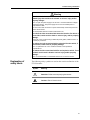
Explanation of
safety labels
The following safety symbols are used on the exterior and interior of the
ET 350 monitor:
Symbol
Meaning
Attention: Refer to accompanying documents
Caution: Risk of electric shock
iii
Renseignements sur la sécurité du
produit
Utilisation
Le moniteur 3M DynaproTM ET 350 (modèles ET 350R, ET 350L2 et ET 350L3)
sert à fournir des fonctions pour écran tactile lorsqu’il est branché à un ordinateur
hôte dans un environnement industriel. Le moniteur ET 350 n’est pas destiné à
être utilisé dans des endroits dangereux.
Avertissement
Afin de réduire les risques d’incendie ou d’explosion causant des blessures
corporelles sérieuses ou mortelles :
N’installez pas ou n’utilisez pas ce produit dans un lieu dangereux.
Lorsque vous utilisez une solution ou un fluide nettoyant inflammable ou
combustible sur ou près du moniteur ET 350, veuillez vous référer à la fiche
technique du manufacturier du matériel de nettoyage et suivez toutes les
instructions et recommendations.
Afin de réduire les risque d’incendie ou de choc électrique causant des
blessures corporelles sérieuses ou mortelles :
Suivez toutes les instructions d’installation du produit et des accessoires.
Tout entretien ou autre procédure qui n’est pas décrite dans ce manuel doit
être réalisée seulement par le personnel du service de 3M Touch Systems.
Pour le moniteur ET 350R dans un environnement à polution de type 3,
installez l’unité dans une enveloppe scellée selon le standard NEMA 4X/IP66.
Installez le moniteur ET 350 à proximité de la source d’alimentation afin que
l’unité puisse être débranchée facilement et rapidement. Pour l’équipement
branché en permanence, un dispositif de débranchement facile d’accès doit
être incorporé au filage fixe.
Supervisez l’installation du moniteur ET 350 et prenez en considération
l’environnement d’opération (comme par exemple les facteurs thermiques et
l’exposition aux chocs et aux vibrations).
Fournissez une mise à terre fiable et propre.
Au moment du branchement de l’alimentation avec câblage d’excitation fixe,
le câble d’alimentation doit avoir une double isolation. Un isolant clair et
flexible (fourni) doit couvrir la portion du câble qui n’a pas de double isolement
lors du branchement a un connecteur de plaque à bornes.
L’installation du câblage devrait être effectuée par un maître électricien
autorisé et doit respecter les codes du bâtiment fédéraux et provinciaux.
Lors du remplacement d’un fusible ou d’une autre pièce, utilisez une pièce du
type et du régime nominal indiqué par 3M Touch Systems.
Installez solidement le moniteur ET 350R pour qu’il soit dans un
environnement scellé selon les standards NEMA 4X/IP66.
Installez solidement le moniteur ET 350R avec un joint statique NEMA 4X/IP66
intact et fonctionnel.
N’utilisez pas le moniteur ET 350 qui n’est pas du régime nominal NEMA 4X/
IP66 dans des environnements qui exigent le sceau NEMA 4X/IP66.
N’endommagez pas les joints statiques du moniteur ET 350.
v
Guide d’installation pour utilisateur du moniteur ET 350 3M Dynapro
Avertissement (suite)
Afin de réduire le risque d’électrocution qui peuvent causer des blessures
corporelles sérieuses ou mortelles :
N’ouvrez pas l’alimentation électrique du moniteur ET 350. Il contient des
voltages dangereux. L’alimentation électrique n’a pas de pièces à remplacer
par l’utilisateur ou de dispositifs de réglage à l’intérieur.
Assurez-vous que la différence potentielle de mise à terre entre le moniteur ET
350 et l’ordinateur hôte est de moins de 2V.
Installez un réducteur de tension adéquat pour toutes les communications et
les câbles d’alimentation.
Débranchez l’alimentation de l’unité avant de sortir le moniteur ET 350 de son
support.
Afin de réduire les risques d’électrocution ou de collision mécanique
causant des blessures corporelles sérieuses ou mortelles :
Sélectionnez un réglage “safe touch”, surtout si le moniteur tourne avec une
application ou si le réglage de la sécurité est en question.
Utilisez seulement un économiseur d’écran pour système d’exploitation
Windows sinon cela pourrait affecter le réglage “safe touch” et pourrait
démarrer et stopper les périphériques qui y sont branchés par inadvertance
Réglez correctement les paramètres safe touch où le nombre de minutes
entrées pour l’économiseur d’énergie du système d’exploitation Windows doit
être au moins une minute de plus que le temps entré pour l’économiseur
d’écran du système d’exploitation Windows.
Ne mettez pas le système de gestion de l’alimentation de l’afficheur (DPMS)
hors tension, qui est configurable à partir du menu Utilitaire à l’écran de
l’afficheur.
Avertissement
Afin de réduire les risques de blessures mineures ou modérées provenant
du contact avec des solutions ou de fluides nettoyants, par ingestion et au
contact de la peau :
Veuillez vous référer à la fiche technique sur la sécurité du manufacturier du
matériel de nettoyage et suivre toutes les instructions et recommendations.
Afin de réduire les risques d’électrocution ou d’incendie causant des
blessures mineures ou modérées ou des dommages à l’équipement :
Si le moniteur ET 350 doit être utilisé dans des environnements corrosifs, il est
de la responsabilité de l’utilisateur de tester et d’évaluer le moniteur dans de
tels environnements. Le moniteur, tel que livré, n’a pas été évalué pour une
utilisation dans des environnements corrosifs et son utilisation dans de tels
environnements, sans évaluation et test préalables, peut créer des conditions
d’utilisation non-sécuritaires.
Afin de réduire les risques de fatigue musculaire causant des blessures
mineures ou modérées ou des dommages à l’équipement :
N’utilisez pas le moniteur ET 350 pour de longues périodes sans pause.
Afin de réduire les risques de fatigue de l’oeil causant des blessures
mineures ou modérées ou des dommages à l’équipement :
Utilisez le moniteur dans des endroits qui ne sont pas trop éclairés ou
produisant des reflets sur l’écran.
Afin de réduire les risques de contamination environnementale causant
des blessures mineures ou modérées ou des dommages à l’équipement :
Disposez du moniteur selon les lois gouvernementales applicables.
vi
Renseignements au sujet de la sécurité du produit
Avertissement
Pour réduire les risques de décharges électriques ou de brûlures
susceptibles, faute de précaution, de causer la mort, des blessures graves
et/ou des dommages matériels :
Ne pas ouvrir le bloc d’alimentation du terminal ET. Il comporte des tensions
dangereuses. Le bloc d’alimentation ne renferme aucune pièce ni aucun
dispositif de réglage remplaçable par l’utilisateur.
Éviter tout contact avec les connecteurs du bornier avant d'avoir coupé
l'alimentation.
Ne pas toucher aux fils électriques à découvert à l'intérieur du terminal ET.
Pour réduire les risques de décharges électriques ou d'incendie
susceptibles, faute de précaution, de causer la mort, des blessures graves
et/ou des dommages matériels :
Si le terminal ET a été assemblé à l'aide d'un joint NEMA 4X, installer le
terminal dans un endroit homologué UL.
Pour réduire les risques de problème mécanique susceptibles, faute de
précaution, de causer la mort, des blessures graves et/ou des dommages
matériels :
Ne pas faire fonctionner le terminal ET 350 dans des conditions différentes de
celles qui sont spécifiées.
Pour réduire les risques d’incendie et d'explosion susceptibles, faute de
précaution, de causer la mort, des blessures graves et/ou des dommages
matériels :
Ne pas utiliser de produits de nettoyage inflammables ou combustibles sur le
moniteur ou à proximité de celui-ci.
\Signification des
étiquettes de
sécurité
Les symboles de sécurité suivants sont utilisés à l’intérieur et l’extérieur
du moniteur ET 350:
Symbole
Signification
Attention : référez-vous aux documents
d’accompagnement
Mise en garde : risque d’électrocution
vii
Informatie productveiligheid
Voorgenomen gebruik
TM
De 3M Dynapro ET 350 monitor (met name de modellen ET 350R, ET 350L2,
en ET 350L3) dient als aanraakbeeldscherm wanneer deze is aangesloten op
een hostcomputer in een industriële omgeving. De ET 350 monitor is niet bedoeld
voor gebruik in gevaarlijke omgevingen.
Waarschuwing
Om het gevaar van persoonlijk letsel als gevolg van brand of
explosies te beperken:
Plaats dit apparaat niet in een gevaarlijke omgeving.
Raadpleeg het veiligheidsinformatieblad van de reinigingsfabrikant bij het
gebruik van ontvlambare of explosieve schoonmaakvloeistoffen in de nabijheid
van de ET 350 monitor.
Om het gevaar van ernstig of dodelijk persoonlijk letsel als gevolg
van brand of elektrische schokken te beperken:
Volg nauwkeurig de installatie-instructies van dit product en de eventuele
accessoires.
Alle onderhoudswerkzaamheden die niet beschreven worden in deze
handleiding, moeten uitsluitend worden uitgevoerd door 3M Touch Systems
onderhoudspersoneel.
Voor de installatie van de ET 350R monitor in een omgeving met
vervuilingsgraad 3: plaats de eenheid in een afgesloten gedeelte conform de
NEMA 4X/IP66 standaard.
Plaats de ET 350 monitor dichtbij de stroomtoevoer zodat de eenheid snel en
gemakkelijk kan worden uitgezet. Voor permanente installaties moet er een
gemakkelijk toegankelijke schakelaar in de vaste bedrading aanwezig zijn.
Houd bij de installatie van de ET 350 monitor rekening met de omgeving (bijv.
thermale en schok/vibratie factoren).
Zorg voor een schone en betrouwbare aardleiding.
Bij vaste bedradingsaansluitingen is een dubbele isolatiekabel vereist. Een
schone en flexibele isolator (bijgeleverd) moet het gedeelte waar de kabel niet
volledig dubbel is geïsoleerd bedekken wanneer deze wordt aangesloten op
een verbindingsstrip connector.
De montage van de bedrading moet worden gedaan door een erkende
elektricien en voldoen aan de lokale en nationale voorschriften voor elektrische
installaties.
Gebruik bij het vervangen van een zekering of ander onderdeel de typen en
classificaties zoals gespecificeerd door 3M Touch Systems.
Plaats de ET 350R monitor in een afgesloten gedeelte volgens de NEMA 4X/
IP66 standaard.
Plaats de ET 350R monitor in een onbeschadigde en werkzame NEMA 4X/
IP66 pakking.
Gebruik een ET 350 monitor die niet voldoet aan de NEMA 4X/IP66 standaard
niet in omgevingen die een NEMA 4X/IP66 afsluiting vereisen.
Beschadig de ET 350 monitor pakking niet.
ix
3M Dynapro ET 350 Monitor Gebruikershandleiding voor Installatie
Waarschuwing (vervolg)
Om het gevaar van ernstig of dodelijk persoonlijk letsel als gevolg
van elektrische schokken te beperken:
Maak de vermogensvoeding van de ET 350 monitor niet open. Deze bevat een
gevaarlijk voltage. De vermogensvoeding bevat geen onderdelen die
aanpassing of onderhoud vergen door gebruikers.
Verzeker u ervan dat het voltage tussen de ET 350 monitor en de
hostcomputer minder dan 2 Volt bedraagt.
Zorg voor voldoende trekontlasting voor alle stroom- en communicatiekabels.
Sluit de stroom af voordat u de ET 350 monitor van de ophanging loskoppelt.
Om het gevaar van ernstig of dodelijk persoonlijk letsel als gevolg
van elektrische of mechanische schokken te beperken:
Gebruik een “safe touch” instelling. Zeker wanneer er een applicatie op de
monitor draait of in een opstelling waar veiligheid van essentieel belang is.
Gebruik geen screensavers die niet door Windows wordt ondersteund: deze
kunnen de “safe touch” instelling aantasten en het onwillekeurig starten of
stoppen randapparatuur veroorzaken.
Stel de “safe touch” op de juiste manier in: het aantal ingevoerde minuten voor
de energiebesparing van het Windows besturingssysteem moet tenminste één
minuut langer duren dan de screensaver van het Windows besturingssysteem.
Zet het display power management system (DPMS) niet uit. Deze is te
configureren in de instellingen van de monitor via het Utility menu.
Voorzichtig
Om het gevaar van klein of middelmatig letsel als gevolg van
huidcontact of inslikking van reinigingsproducten te beperken:
Raadpleeg het veiligheidsinformatieblad van de reinigingsfabrikant en volg de
instructies en adviezen.
Om het gevaar van klein of middelmatig letsel of materiaalschade
als gevolg van brand of elektrische schokken te beperken:
Wanneer de ET 350 monitor wordt gebruikt in corrosie vormende omgevingen,
is het de verantwoordelijkheid van de gebruiker om de uitwerking van dit soort
omgevingen op de monitor te testen en te evalueren. De monitor is na
productie niet getest voor gebruik in corrosie vormende omgevingen en het
gebruik van de monitor in zulke omgevingen kan leiden tot onveilige situaties.
Om het gevaar van klein of middelmatig letsel als gevolg van
spierverrekingen te beperken:
Vermijd het langdurig gebruik zonder pauze van de ET 350 monitor.
Om het gevaar van klein of middelmatig letsel als gevolg van
overbelasting van de ogen te beperken:
Vermijd het gebruik van de monitor op plaatsen waar omringend licht of
geschitter in het beeldscherm weerkaatsen.
Om het gevaar van klein of middelmatig letsel of materiaalschade
als gevolg van mileuvervuiling te beperken:
Verwerk, na gebruik, monitor conform de wettelijke milieurichtlijnen.
x
Informatie productveiligheid
Waarschuwing
Neem het volgende in acht om de risico's van elektrische schokken en/of
brandwonden te reduceren die ernstig letsel, de dood en/of schade aan
eigendommen tot gevolg kunnen hebben:
Maak de voedingsbron in de ET-eenheid niet open. Hierin is een gevaarlijke
spanning/gevaarlijke energie aanwezig. In de voedingsbron bevinden zich
geen onderdelen waaraan door de gebruiker onderhoud mag worden
uitgevoerd of die door de gebruiker mogen worden afgesteld.
Raak de connectors op de voedingsterminalstrip niet aan, tenzij de voeding is
losgekoppeld.
Raak blootliggende elektrische contacten in de ET-eenheid niet aan.
Neem het volgende in acht om de risico's van elektrische schokken of
brand te reduceren die, indien deze niet worden voorkomen, ernstig letsel,
de dood en/of schade aan eigendommen tot gevolg kunnen hebben:
Als de ET-eenheid wordt gemonteerd en er wordt voor het paneel een
NEMA 4X-pakking gebruikt, dient u de eenheid in een aangegeven (UL)
behuizing aan te brengen.
Neem het volgende in acht om de risico's van mechanische werking te
reduceren die, indien deze niet worden voorkomen, schade aan
eigendommen tot gevolg kunnen hebben:
Gebruik de ET 350-eenheid niet onder omstandigheden die buiten de
bedrijfsspecificaties vallen.
Neem het volgende in acht om de risico's van brand en explosies te
reduceren die, indien deze niet worden voorkomen, ernstig letsel, de dood
en/of schade aan eigendommen tot gevolg kunnen hebben:
Gebruik geen ontvlambare of brandbare reinigingsmiddelen voor of in de buurt
van de monitor.
Verklaringen van
de
veiligheidslabels
Onderstaande veiligheidssymbolen worden gebruikt aan de buiten- en
binnenkant van de ET 350 monitor:
Symbool
Betekenis
Pas op: Raadpleeg de bijgeleverde documenten
Waarschuwing: Gevaar op elektrische schokken
xi
Produktsicherheitshinweise
Einsatzbereiche
TM
Der Monitor 3M Dynapro ET 350 (insbesondere die Monitormodelle ET 350R,
ET 350L2, und ET 350L3) bietet im Anschluss an einen Hauptrechner
Kontaktbildschirmfunktionen für industrielle Anwendungsgebiete. Der Monitor
ET 350 ist nicht für den Einsatz in Gefahrenzonen gedacht.
Warnhinweise
Maßnahmen zum Schutz vor Feuer- oder Explosionsgefahren, die
zu schweren Verletzungen oder sogar zu Todesfällen führen
können:
Produkt nicht in Gefahrenzonen installieren.
Beim Einsatz von entzündlichen oder brennbaren Reinigungslösungen oder
Flüssigkeiten in der Nähe oder am Monitor ET 350 die Angaben im
Sicherheitsdatenblatt des Herstellers beachten und alle Anweisungen und
Empfehlungen befolgen.
Schutz vor Feuergefahr oder elektrischem Schlag, der zu schweren
Körperverletzungen oder Tod führen kann:
Alle Montageanweisungen für das Produkt und Zubehör beachten.
Wartungsarbeiten und andere nicht in diesem Handbuch beschriebene
Prozeduren dürfen nur vom Servicepersonal von 3M Touch Systems
ausgeführt werden.
Bei der Montage eines Monitors ET 350R in einer Umgebung mit
Verschmutzungsgrad 3 ist das Gerät in einem Schutzgehäuse zu installieren,
das den Normvorschriften von NEMA 4X/IP66 entspricht.
Installieren Sie den Monitor ET 350 in der Nähe eines Netzanschlusses, damit
das Gerät einfach und schnell aus dem Netz genommen werden kann. Für
Geräte mit dauerhaften elektrischen Anschlüssen ist ein gut zugänglicher
Trennschalter in die elektrische Netzleitung einzubauen.
Planen Sie beim Einbau des Monitors ET 350 die Betriebsumgebung ein (z. B.
Wärmeunterschiede, Stoß - und Erschütterungsfaktoren).
Sorgen Sie für saubere und zuverlässige Erdung.
Beim Netzanschluss mit dauerhaftem Kabelanschluss der Monitortypen das
Netzkabel doppelt isoliert sein. Ein durch-sichtiger und flexibler Isolator
(mitgeliefert) muss beim Anschluss an die Klemmenleiste jeweils das nicht
doppelt isolierte Kabelteil abdecken.
Die elektrische Montage sollte nur von staatlich geprüften Elektrikern
durchgeführt werden und hat allen Bundes- und Landesbaubestimmungen zu
entsprechen.
Beim Ersetzen von Sicherungen oder anderen Teilen sind grundsätzlich nur
Teile einzusetzen, die dem von 3M Touch Systems angegebenen Typ und
Nennwert entsprechen.
Installieren Sie den Monitor ET 350R so, dass er den Umweltversiegelungsbestimmungen der Norm NEMA 4X/IP66 entspricht.
Installieren Sie den Monitor ET 350R mit einer unbeschädigten und
leistungsfähigen Dichtung gem. NEMA 4X/IP66.
Monitore des Typs ET 350, die nicht für NEMA 4X/IP66 zugelassen sind,
sollten nicht in Umfeldern eingesetzt werden, in denen eine Dichtung gemäß
NEMA 4X/IP66 erforderlich ist.
Die Monitordichtungen des ET 350 nicht beschädigen.
xiii
Monitor 3M Dynapro ET 350 Montageanleitung
Warnhinweise (Forts.)
Maßnahmen zum Schutz vor elektrischem Schlag, der zu schwerer
Körperverletzung oder Tod führen kann:
Die Netzteil des Monitors ET 350 nicht öffnen, da es unter gefährlicher
Spannung steht. Das Netzteil enthält keine Teile oder Einstellungsmöglichkeiten, die von Benutzern gewartet werden können.
Vergewissern Sie sich, dass der Spannungsunterschied zwischen dem
Monitor ET 350 und dem Hauptrechner nicht mehr als 2 V beträgt.
Achten Sie auf geeignete Zugentlastung der Fernmeldekabel und Netzkabel.
Vor dem Entfernen des Monitors ET 350 vom Gestell Netzstecker ziehen.
Schutz vor elektrischem Schlag oder mechanischem Aufprall, der
zu schweren Körperverletzungen oder Tod führen könnte:
Stellen Sie eine “Sichere Berührung” ein, besonders wenn der Monitor mit
einer Anwendung läuft oder in einer Umgebung aufgestellt ist, bei denen
Sicherheitsbedenken bestehen.
Benutzen Sie keinen Bildschirmschoner, der nicht zu einem WindowsBetriebssystem gehört, da dies die Einstellung “Sichere Berührung”
beeinträchtigen könnte und im Gegenzug dazu führen könnte, das
angeschlossene Peripheriegeräte ungewollt ein- oder ausgeschaltet werden.
Stellen Sie die Berührungsangaben richtig ein. Die Anzahl der Minuten bis zum
Einsetzen der Energiesparoption im Windows-Betriebssystem sollte
mindestens eine Minute größer sein als die Zeit bis zum Einschalten des
Bildschirmschoners im Windows-Betriebssystem.
Stellen Sie das Stromzufuhrsystem für die Anzeige (DPMS), das aus dem
Dienstprogramm-Menü konfiguriert wird, auf keinen Fall ab.
Vorsicht
Schutz vor geringfügigen oder leichten Verletzungen durch den
Kontakt mit Reinigungslösungen oder -flüssigkeiten durch
Einnahme oder Hautberührung:
Angaben im Sicherheitsdatenblatt des Herstellers beachten und alle
Anweisungen und Empfehlungen befolgen.
Schutz vor elektrischem Schlag oder Feuergefahr, die zu
geringfügigen oder leichten Verletzungen oder Sachschäden führen
könnte:
Sollte der Einsatz des Monitors ET 350 in zersetzenden Umfeldern geplant
sein, ist der Benutzer dafür verantwortlich, die Eignung des Monitors für diese
Umgebung zu überprüfen. Der Monitor wurde in der gelieferten Version nicht
auf die Eignung für den Einsatz in zersetzenden Umfeldern geprüft. Der
Einsatz in solchen Umfeldern ohne vorherige Prüfung kann zu mangelhaften
Sicherheitsbedingungen führen.
Schutz vor Muskelüberanstrengung, die zu geringfügigen oder
leichten Verletzungen oder Sachschäden führen könnte:
Den Monitor ET 350 nicht für lange Zeit ohne Pause benutzen.
Schutz vor Überanstrengung der Augen, die zu geringfügigen oder
leichten Verletzungen oder Sachschäden führen könnte:
Monitor nur in Arbeitsumgebungen mit ausreichender Beleuchtung und mit
Schutz vor Bildschirmreflexion einsetzen.
Schutz vor Umweltgefahren, die zu geringfügigen oder leichten
Verletzungen oder Sachschäden führen könnten:
Monitor gemäß allen einschlägigen behördlichen Bestimmungen entsorgen.
xiv
Produktsicherheitshinweise
Warnhinweise
Maßnahmen zum Schutz vor Elektroschock- bzw. Verbrennungsrisiken, die
zu schweren Unfällen mit Todes- oder Verletzungsfolge bzw. Sachschäden
führen können:
Das Netzteil des ET-Monitors nicht öffnen, da es unter gefährlicher
Stromspannung steht. Das Netzteil enthält keine Teile oder
Einstellungsmöglichkeiten, die vom Benutzer gewartet werden können.
Die Verbindungen auf der Klemmleiste nur berühren, wenn die Stromzufuhr
unterbrochen ist.
Vermeiden Sie freiliegende elektrische Kontakte innerhalb des ET-Monitors.
Maßnahmen zum Schutz vor Elektroschock- und Feuerrisiken, die zu
schweren Unfällen mit Todes- oder Verletzungsfolge bzw. Sachschäden
führen können:
• Wenn der ET-Monitor mit Hilfe einer Dichtung gem. NEMA 4X montiert wird,
installieren Sie die Einheit in einem eingetragenen (UL) Gehäuse.
Maßnahmen zum Schutz vor Risiken in Verbindung mit mechanischen
Funktionen, die zu Sachschäden führen können:
Betreiben Sie den ET-Monitor nicht unter Bedingungen, die außerhalb der
Betriebsspezifikationen liegen.
Maßnahmen zum Schutz vor Feuer- und Explosionsrisiken, die zu
schweren Unfällen mit Todes- oder Verletzungsfolge bzw. Sachschäden
führen können:
Keine entzündlichen oder brennbaren Reinigungsmittel an oder in der Nähe
des Monitors verwenden.
Erklärung der
Sicherheitsetiketten
Die folgenden Sicherheitssymbole sind auf der Außen- und Innenseite des
Monitors ET 350 angebracht:
Symbol
Bedeutung
Warnung: Bitte beiliegende Dokumentation beachten
Vorsicht: Elektrische Schlaggefahr
xv
y
Informazioni per la sicurezza
Applicazioni d’impiego del prodotto
Il monitor 3M DynaproTM ET 350, in particolare i modelli ET 350R, ET 350L2 e
ET 350L3, è destinato all'uso come monitor a schermo tattile in collegamento a
un computer host in ambiente industriale. Il monitor ET 350 non è progettato per
l’utilizzo in ambienti pericolosi.
Avvertenza
Precauzioni per ridurre il rischio di incendi o esplosioni che
potrebbero causare lesioni gravi o fatali:
Non installare o utilizzare il prodotto in ambienti pericolosi.
Se si utilizzano prodotti liquidi infiammabili o combustibili per la pulizia del
monitor ET 350 o nelle immediate vicinanze, consultare le istruzioni per la
sicurezza e seguire attentamente tutte le istruzioni e raccomandazioni per
l'uso di tali prodotti.
Precauzioni per ridurre il rischio di incendi o scosse elettriche che
potrebbero causare lesioni gravi o fatali:
Seguire tutte le istruzioni per l'installazione del prodotto e dei suoi accessori.
Per operazioni di manutenzione o altre procedure non descritte in questo
manuale, rivolgersi solo a personale di assistenza 3M Touch Systems.
Per il monitor ET 350R in ambiente di inquinamento Classe 3, installare l'unità
in un contenitore sigillato secondo lo standard NEMA 4X/IP66.
Installare il monitor ET 350 nei pressi di una presa di alimentazione elettrica,
in modo tale che l'unità possa essere scollegata in modo semplice e rapido.
Per i dispositivi collegati in modo permanente, installare un dispositivo di
scollegamento di facile accesso e incorporato nei cavi di alimentazione.
Progettare l'installazione del monitor ET 350 tenendo in considerazione
l'ambiente di lavoro (per esempio, temperatura, urti o vibrazioni, ecc.).
Installare una messa a terra sicura e affidabile.
Quando si collega l'alimentazione elettrica per mezzo di cavi fissi, i cavi di
alimentazione devono essere dotati di doppio isolamento. Il segmento di cavo
utilizzato per il collegamento a un terminale a morsettiera deve essere dotato
di un isolatore flessibile e trasparente (in dotazione) che deve coprire la
porzione di cavo priva di doppio isolamento.
I collegamenti devono essere effettuati da un elettricista qualificato e nel
rispetto dei regolamenti nazionali e locali per la sicurezza elettrica.
La sostituzione di fusibili o di altre parti deve essere effettuata utilizzando
componenti del tipo indicato da 3M Touch Systems.
Effettuare l'installazione del monitor ET 350R secondo le indicazioni di
isolamento ambientale dello standard NEMA 4X/IP66.
Installare correttamente il monitor ET 350R con una guarnizione NEMA 4X/
IP66 integra ed in perfetta efficienza.
Non utilizzare un monitor ET 350 non approvato NEMA 4X/IP66 in ambienti
che richiedono l'isolamento NEMA 4X/IP66.
Non danneggiare le guarnizioni del monitor ET 350.
xvii
Guida per l’installazione del Monitor 3M Dynapro ET 350
Avvertenza (segue...)
Precauzioni per ridurre il rischio di scosse elettriche che
potrebbero causare lesioni gravi o fatali:
Non aprire l'alimentatore del monitor ET 350. Esso contiene parti sotto
tensione elevata. L'alimentatore non contiene parti che richiedono
manutenzione o regolazione da parte degli utenti.
Assicurare che la differenza di potenziale tra il monitor ET 350 e il computer
host sia inferiore a 2V.
Evitare di sottoporre i cavi per l'alimentazione e per i segnali a sforzi meccanici.
Prima di rimuovere il monitor ET 350 dalla sua base, scollegare
l'alimentazione elettrica.
Precauzioni per ridurre il rischio di scosse elettriche o urti che
potrebbero causare lesioni gravi o fatali:
Utilizzare l'impostazione “safe touch”, in particolare se il monitor viene usato
in applicazioni o ambienti in cui la sicurezza assume particolare importanza.
Non utilizzare uno "screen saver" non Windows per non rischiare di alterare
l'impostazione “safe touch” e di conseguenza causare l'avvio o l'arresto
indesiderato di periferiche o macchinari collegati.
Impostare la funzione "safe touch", con il numero di minuti per il risparmio
energetico del sistema operativo Windows fissate impostato ad almeno un
minuto oltre il tempo stabilito per l'entrata in funzione dello screen saver.
Non disattivare il DPMS (Display Power Management System), configurabile
dal menu Utility del monitor.
Attenzione
Precauzioni per ridurre il rischio di lesioni minori o non gravi che
potrebbero derivare dal contatto con fluidi o soluzioni per la pulizia,
tramite ingestione o contatto con la pelle:
Consultare le istruzioni per la sicurezza nell'uso dei materiali e seguire
attentamente le istruzioni e i consigli del produttore.
Precauzioni per ridurre il rischio di scossa elettrica o incendio con
conseguenti lesioni minori o non gravi oppure danni materiali:
Se il monitor ET 350 viene utilizzato in ambienti corrosivi, è responsabilità
dell'utente la verifica e la valutazione per l'utilizzo in tali ambienti. Il monitor,
nelle condizioni standard di fornitura, non è approvato per l'utilizzo in ambienti
corrosivi ed il suo utilizzo senza effettuare le ncecessarie verifiche e
valutazioni potrebbe comportare condizioni d'uso non sicure.
Precauzioni per ridurre il rischio di sforzi muscolari con
conseguenti lesioni minori o non gravi oppure danni materiali:
Evitare l'utilizzo del monitor ET 350 per lunghi periodi di tempo senza pause.
Precauzioni per ridurre il rischio di stanchezza oculare con
conseguenti lesioni minori o non gravi oppure danni materiali:
Non utilizzare il monitor in ambienti troppo luminosi ed evitare i riflessi sullo
schermo.
Precauzioni per ridurre il rischio di inquinamento dell'ambiente che
potrebbe causare lesioni minori o non gravi oppure danni materiali:
Effettuare lo smaltimento del monitor nel rispetto delle norme di legge.
xviii
Informazioni per la sicurezza
Attenzione
Per limitare o prevenire il rischio di scosse elettriche e/o di ustioni che
potrebbero provocare incidenti gravi o mortali e/o danni alle attrezzature,
attenersi alle istruzioni riportate di seguito:
Non aprire l'alimentatore del monitor ET, poiché contiene componenti con una
tensione e una potenza pericolose. L'alimentatore non contiene componenti
interni la cui manutenzione o regolazione può essere eseguita dagli utenti.
Toccare i connettori sulla morsettiera solo se il monitor è scollegato dalla rete.
Non toccare i contatti elettrici non protetti all'interno del monitor ET.
Per limitare o prevenire il rischio di scosse elettriche o di incendi che
potrebbero provocare incidenti gravi o mortali nonché danni alle
attrezzature, attenersi alle istruzioni riportate di seguito:
Se il monitor ET deve essere montato utilizzando una tenuta per pannelli di
tipo NEMA 4X, installare l'unità in un alloggiamento di classe UL.
Per limitare o prevenire i rischi connessi a funzioni meccaniche che
potrebbero danneggiare le attrezzature, attenersi alle istruzioni riportate di
seguito:
Utilizzare il monitor ET solo entro gli intervalli operativi indicati nelle specifiche.
Per limitare i rischi di incendi e esplosioni che potrebbero provocare
incidenti gravi o mortali e/o danni alle attrezzature, attenersi alle istruzioni
riportate di seguito:
Non utilizzare detergenti infiammabili o combustibili per pulire il monitor o le
aree circostanti.
Illustrazione del
significato dei
simboli per la
sicurezza
I seguenti simboli per la sicurezza vengono utilizzati nelle parti esterne ed
interne del monitor ET 350:
Simbolo
Significato
Attenzione: Consultare la documentazione di
accompagnamento
Attenzione: Rischio di scossa elettrica
xix
Información de seguridad del
producto
Uso deseado
El monitor 3M DynaproTM ET 350 (en particular, los modelos ET 350R, ET 350L2,
y ET 350L3) está diseñado para proveer funciones de pantalla táctil cuando se lo
conecte a una computadora central en un ambiente industrial. El monitor ET 350
no fue pensado para operar en ubicaciones peligrosas.
Advertencia
Para reducir el riesgo de incendio o explosión que podría resultar en
lesiones personales graves o muerte:
No instale o utilice este producto en ubicaciones peligrosas.
Cuando utilice una solución o líquido de limpieza inflamable o combustible en
el monitor ET 350 monitor o cerca del mismo, refiérase a las planillas de datos
de seguridad del fabricante y siga todas las instrucciones y recomendaciones.
Para reducir el riesgo de incendio o choque eléctrico, que podría
resultar en lesiones personales severas o muerte:
Siga todas las instrucciones de instalación del producto y sus accesorios.
Todo procedimiento de mantenimiento no descripto en este manual deberá ser
realizado, exclusivamente, por el personal de mantenimiento de 3M Touch
Systems.
Con respecto al monitor ET 350R a ubicar en un ambiente con una
contaminación grado 3, instale la unidad en un gabinete aprobado según el
estándar NEMA 4X/IP66.
Instale el monitor ET 350 cerca de la fuente de alimentación, a fin de que la
unidad pueda ser fácil y rápidamente desconectada. Para el equipo conectado
de manera permanente, habrá que incorporar al cableado fijo un dispositivo de
desconexión de rápido acceso.
Prepare la instalación del monitor ET 350 tomando en cuenta el ambiente
operativo (por ejemplo, factores térmicos, choque/vibración, etc.).
Provea una base limpia y confiable.
Cuando conecte la alimentación con cables de campo fijo, el cable de
alimentación deberá tener aislación doble. El aislante transparente y flexible
(que se provee con el equipo) debe cubrir la porción del cable que no tiene
aislación doble cuando se lo conecta al conector de regletas terminales.
La instalación del cableado debe ser realizada por un electricista calificado y
cumplir con los códigos eléctricos locales y federales.
Cuando reemplace un fusible u otro repuesto, use un repuesto del tipo y
clasificación especificados por 3M Touch Systems.
Instale el monitor ET 350 R como corresponda, a fin de que quede sellado
desde el punto de vista del ambiente, tal cual lo dispone el estándar NEMA 4X/
IP66.
Instale el monitor ET 350R con una junta NEMA 4X/IP66 que esté intacta y
efectiva.
No utilice un monitor ET 350 que no esté calificado para NEMA 4X/IP66 en
ambientes que requieran un sello NEMA 4X/IP66.
No dañe ninguna de las juntas del monitor ET 350.
xxi
Monitor 3M Dynapro ET 350 - Guía de Instalación del Usuario
Advertencia (continuación)
Para reducir el riesgo de choque eléctrico que podría resultar en
lesiones personales severas o muerte:
No abra la fuente de alimentación del monitor ET 350. Contiene tensiones
peligrosas. La fuente de alimentación no cuenta en su interior con partes o
ajustes atendibles por el usuario.
Asegúrese que la diferencia de potencial de masa entre el monitor ET 350 y la
computadora central sea menor de 2V.
Provea un alivio adecuado de la tensión para todos los cables de
comunicaciones y alimentación.
Antes de retirar al monitor ET 350 de su instalación, desconecte la
alimentación de la unidad.
Para reducir el riesgo de choque eléctrico o impacto mecánico que podrían
resultar en lesiones personales severas o muerte:
Aplique una configuración de “contacto seguro”, especialmente si el monitor
está ejecutando una aplicación o si se encuentra en una configuración que
puede afectar la seguridad.
No utilice un protector de pantalla que no pertenezca al sistema operativo
Windows que pueda afectar la configuración de “contacto seguro” y a su vez,
podría provocar el arranque o interrupción inadvertida del equipo periférico
conectado.
Configure el contacto seguro como corresponda, debiendo ser el número de
minutos ingresado para el ahorrador de energía del sistema operativo
Windows, mayor en un minuto, por lo menos, al tiempo ingresado para el
protector de pantalla de Windows.
No desconecte el sistema de gestión de energía (DPMS) del monitor,
configurable desde el menú Utility (Utilitarios) visualizado en la pantalla.
Precaución
Para reducir el riesgo de lesiones leves o moderadas por el contacto
con soluciones o líquidos de limpieza, por la ingestión o contacto
con la piel:
Refiérase a los datos de seguridad del fabricante del limpiador y siga todas las
instrucciones y recomendaciones.
Para reducir el riesgo de choque eléctrico o incendio que puede
resultar en lesiones leves or moderadas o provocar daño a la
propiedad:
Si se utilizará al monitor ET 350 en un ambiente propenso a la corrosión, el
usuario será responsable de probar y evaluar al monitor en dichos ambientes.
El monitor, empaquetado y enviado, no fue evaluado para ser usado en
ambientes corrosivos y su uso en dichos ambientes, sin una correcta prueba
y evaluación, puede llevara situaciones de riesgo.
Para reducir el riesgo de tensión muscular que puede resultar en
lesiones leves o moderadas o provocar daño a la propiedad:
Evite utilizar el monitor ET 350 por períodos prolongados sin interrupción.
Para reducir el riesgo de tensión ocular que puede resultar en
lesiones leves o moderadas o provocar daño a la propiedad:
Utilice el monitor en sitios que no impongan demasiada luz natural o reflejo
sobre la pantalla.
Para reducir el riesgo de contaminación ambiental que puede
resultar en lesiones leves o moderadas o provocar daño a la
propiedad:
Disponga del monitor de acuerdo con las regulaciones gubernamentales
válidas en su zona.
xxii
Información de seguridad del producto
Advertencia
Para disminuir los riesgos relacionados con descargas eléctricas y
quemaduras, los cuales, si no se evitan, pueden ocasionar la muerte,
lesiones graves o daño a la propiedad:
• No abra la unidad de suministro de energía de la unidad ET, pues contiene
energía o voltaje peligroso. La unidad de suministro de energía no contiene
piezas a las que pueda dar servicio ni ajustar el usuario.
• Evite el contacto con conectores en las regletas de las terminales de energía
a menos que la energía esté desconectada.
• Evite contactos eléctricos expuestos dentro de la unidad ET.
Para disminuir los riesgos relacionados con descargas eléctricas e
incendios, los cuales, si no se evitan, pueden ocasionar la muerte, lesiones
graves o daño a la propiedad:
Si la unidad ET está montada utilizando un empaque de panel NEMA 4X,
instale la unidad en un lugar certificado (UL).
Para disminuir los riesgos relacionados con el funcionamiento mecánico,
los cuales, si no se evitan, pueden ocasionar daño a la propiedad:
No haga funcionar la unidad ET en condiciones que se salgan de las
especificaciones de uso.
Para disminuir los riesgos relacionados con incendios y explosiones, los
cuales, si no se evitan, pueden ocasionar la muerte, lesiones graves o daño
a la propiedad:
No utilice limpiadores inflamables o combustibles en el monitor o cerca de
éste.
Explicación de los
rótulos de
seguridad
Los siguientes ssímbolos de seguiridad se utilizan en el interior y el
exterior del monitor ET 350:
Símbolo
Significado
Atención: Refiérase a la documentación adjunta.
Precaución: Peligro de choque eléctrico.
xxiii
3M DynaproTM ET 350 ET350R ET 350L2 ET350L3
ET350 !"#
$%&
!"#'()*+,-
.*/01 01234)4 56)7 ET350 8
;<=>?@'ABCD EFG#H>IJKL
$9:
$FG#H,-MN>'(IJ
OPQR)ST&+UVWXHIJ>YZ[\ 3M Touch Systems
3M ]^ QR_`ab
&cde (Pollution Degree) 3 >fgh
NEMA 4X/IP66 lm>nopqW
ET 350R i'(&jk
ET 350 i'(&7rstu>vw Gxywzx{|v}~r
s
rs1v &M
8'(zY>
(
'( ET 350 8iYfg /
iA >v
ET 350L3 ET 350R >"
rs
8 rs
¡¢£¤> &k
¥t¦8§>X
H¡¢£¤>r¨©ª «¬ ®>£¤¯ ° S±²
M
(\³k´>µ¶r·¸ ¹º»¼½.v>r¾
¿À
ÁÂÃ!Ä)STÅN8 iÆ 3M Touch Systems 3M ]^ U
>ÇÈÉ
ifgno> NEMA4X/ IP66 lm ÊË'( ET 350R *ÌxHÍ> NEMA 4X/IP66 ÎÏ
ÊË'( ET 350R &Ðjk NEMA 4X/IP66 nolm>fgh
NEMA 4X/IP66 nolm> ET 350 $%*Ñljk
$%ÒÓOP ET 350 >ÎÏ
xxv
3M Dynapro ET 350 $%Ô ET 350 W>rs Õ¯HÖ×> !rØ
ÙQR)ÚÛ>ÅN
ËÃ ET 350 ÜÝ>vrÞßà 2V
rsWXHÐ
ËÃ#Há
rs
¨âHã.>äeåæ
& ET 350 G(Mçèéê $}~Srs
ëS ìÊ&íbîiïð )îiñòóô'A8
i 'A $%*õ Windows Y]^>öÃ÷ïð øù[úûü 'A
Gxýþ
S>pÿ§Ô)
ÊË'A * Windows Y]^Û[ïð>8Ý
Windows Y]^öÃ÷ïð>8Ý
1 ª
$%>rs]^ (DPMS) ìrs]^Göè
> Utility ïð
DWabM
減小電擊和/或灼傷危險,否則可能造成死亡或嚴重傷害和/或財產損:
•切勿打開ET裝置中的電源。其中帶有危險性電壓/危險性能量。電源內
部沒有使用者可維修的零部件或調節。
• 避免接觸電源端子帶上的連接器,除非已斷開電源。
• 避免接觸ET裝置內部的裸露電氣部件。
減小電擊或失火危險,若不加以防範,會造成死亡或嚴重傷害和/或財
產損失:
•果是使用NEMA 4X面板襯墊安裝ET裝置,則在列出的(UL)殼罩內安裝
該裝置。
減小機械功能危險,若不加以防範,可能導致財產損失:
• 切勿在操作規範之外的條件下操作ET裝置。
減小失火和爆炸的危險,若不加以防範,可能造成死亡或嚴重傷害和/
或財產損失:
• 在監視器上或附近切勿使用可燃或易燃清潔器。
!"#$%&'()*+ ,-.//0()
1232
$9:2;<=>?@'ABCD
EFG#H>IJKL
1232 4567
ET 350 1>fgW *HO&ìfgh
ab ì&§êXH&1>fgW &
ìfgh XHab [úýþ !
8961232 4567
ä8ÝÝ~v* ET 350 :;<=1232 4567
[&
!>fgW*
¹ö[
"#
>?@A1232 4567
xxvi
ã>$%À&·'
5BCDEF
ET 350 GH
IJ
KL MNOPQRS
TU xxvii
Contents
Before you start
About the User’s Installation Guide................................. 1
Topics ........................................................................................................ 1
Warnings and cautions .............................................................................. 1
Related documents .................................................................................... 1
Terms......................................................................................................... 2
Product support ......................................................................................... 3
Contacting 3M Touch Systems ................................................................. 3
Chapter 1
Introducing the ET 350 monitor........................................ 5
Packing lists............................................................................................... 5
Standard features ....................................................................................... 6
Distinctive features of each model ............................................................ 8
Options .................................................................................................... 10
Mounting kits .......................................................................................... 11
Chapter 2
Installing the monitor ...................................................... 13
Installation summary ............................................................................... 13
Before installing ...................................................................................... 14
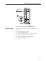
Step 1: Connect video (VGA) signal cable ............................................ 14
Step 2: Connect serial cable .................................................................... 15
Step 3: Connect to power supply............................................................. 16
Step 4: Adjust display settings ................................................................ 19
Step 5: Install software and import TouchSurround files ....................... 22
Step 6: Set “backlights saver” and “safe touch” ..................................... 25
Step 7: Close enclosure and hatch........................................................... 28
Step 8: Mount monitor ............................................................................ 28
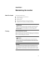
Chapter 3
Maintaining the monitor .................................................. 31
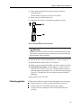
Cleaning .................................................................................................. 31
Replacing backlights ............................................................................... 32
Replacing the fuse ................................................................................... 32
Checking gaskets..................................................................................... 33
Maintaining the ET 350 monitor with Moisture Deflector ..................... 34
Chapter 4
TouchSurround and graphic underlay .......................... 35
About the TouchSurround ....................................................................... 35
Replacing a TouchSurround graphic underlay ........................................ 37
Chapter 5
Troubleshooting .............................................................. 45
General problems .................................................................................... 45
Touch screen driver error messages ........................................................ 47
Appendix A
Appendix B
Appendix C
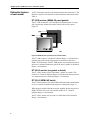
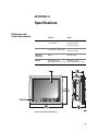
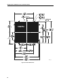
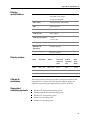
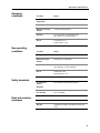
Specifications .................................................................. 49
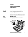
Installing monitor with KVM extender ........................... 57
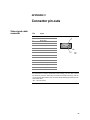
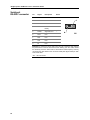
Connector pin-outs.......................................................... 63
xxix
List of Figures
Figure 1: 3M Dynapro ET 350 monitor ................................................... 6
Figure 2: NEMA 4X panel gasket (comes with ET 350R) ...................... 8
Figure 3: NEMA 4X hatch and extended cover (comes with ET 350L3) 9
Figure 4: Moisture Deflector option....................................................... 11
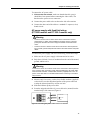
Figure 5: Connectors: ET 350 monitor (without KVM extender) ......... 14
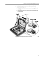
Figure 6: Connecting AC power cable wires to connectors................... 17
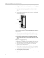
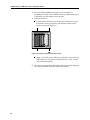
Figure 7: Terminal connection for AC power (ET 350R, ET 350L3
monitors) and for DC power............................................................ 18
Figure 8: Connecting DC power cable wires to connectors................... 19
Figure 9: PC menu options..................................................................... 20
Figure 10: Auto display setup ................................................................ 21
Figure 11: Loosening fuse holder........................................................... 32
Figure 12: Removing fuse from fuse holder .......................................... 33
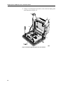
Figure 13: Location of optional security screws .................................... 38
Figure 14: Disconnecting touch screen tail connector ........................... 39
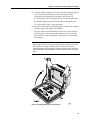
Figure 15: Removing display panel nuts and washers ........................... 40
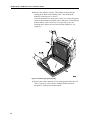
Figure 16: Sliding display pan out and lifting it..................................... 41
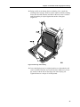
Figure 17: Removing original underlay ................................................. 42
Figure 18: Placing new underlay............................................................ 43
Figure 19: Reconnecting touch screen tail ............................................. 44
Figure 20: Enclosure dimensions ........................................................... 49
Figure 21: Cutout dimensions ................................................................ 50
Figure 22: Enclosure of ET 350 monitor with KVM extender .............. 57
Figure 23: Connectors: ET 350 monitor with KVM extender ............... 61
xxxi
BEFORE YOU START
About the User’s Installation
Guide
Topics
This manual is written for system integrators and day-to-day users of the
3M DynaproTM ET 350 monitor. The manual covers the following topics:
Installing communication and power cables
Installing the touch screen software
Adjusting display settings
Mounting the monitor
Maintaining and cleaning the monitor
Customizing and replacing a TouchSurroundTM graphic underlay
Warnings and
cautions
For a list of all warnings and cautions that appear in this manual, see
“Product safety information”, starting on page i.
For information on the safety symbols used on the interior and exterior of
the monitor, see “Explanation of safety labels” on page iii.
Related documents
Mounting instructions for ET 350R and ET 350L3
monitors
If you ordered either the ET350R monitor or the ET 350L3 monitor, one
of these installation instruction documents will ship with this manual and
your monitor (and are also available for download from the 3M Touch
Systems web site: www.3Mtouch.com):
Installing the NEMA 4X Panel Gasket (comes with ET 350R monitor)
Installing the NEMA 4X Hatch (comes with ET 350L3 monitor)
For more information on ET 350 monitor models, see “Distinctive features
of each model” on page 8.
Instructions for optional mounting kits
For information on optional mounting kits and the installation instructions
that accompany those kits, see “Optional mounting kits” on page 28.
1
3M Dynapro ET 350 Monitor User’s Installation Guide
Software guides
The ET 350 monitor User’s Installation Guide explains how to install
touch screen software that will run with operating systems supported by
the ET 350 (see Chapter 2).
For information on how to customize the software, refer to one of the
following manuals. Both of these software guides may be downloaded
from the 3M Touch Systems web site (www.3Mtouch.com).
For Windows XP Professional and Windows 2000 Professional
operating systems, refer to: MicroTouch NFI Software Guide for
Windows XP and Windows 2000.
ForWindows NT 4.0 and Windows 9X operating systems, refer to:
Configuration Utilities User’s Guide.
README files
On the floppy disks that came with your ET 350 monitor, there are
README files with driver installation instructions and other driver
information.
Terms
This term
Refers to
ACPI
Advanced Configuration and Power Interface. A power management feature that is
configurable in Windows operating systems.
Bezel*
The front rim of the unit that contains the touch screen and the TouchSurround.
Display area*
The part of the touch screen that is positioned over the display of the monitor.
Touches in the display area emulate the movements and actions of a mouse.
DPMS
Display power management system. Some ET units allow this energy saving
setting to be changed. For ET 35X monitor models without a heater, the DPMS
should not be turned off. For DPMS instructions for ET 35X monitor models with a
heater, refer to instructions that ship with models with heaters.
Graphic underlay
(also called TouchSurround
underlay)
A graphic that illustrates the TouchSurround and fits behind the touch screen. 3M
Dynapro industrial products may be ordered with standard or custom underlays.
Buttons and controls for the standard underlays are pre-defined; you must define
buttons and controls for custom underlays.
KVM extender
An optional feature of the ET 350 monitor that allows the monitor to be located as
much as 1000 feet (300 meters) from the host computer.
MicroTouchTM Near Field
A touch screen that uses a proprietary imaging technique to generate a precise
profile of a touch from voltage changes in the electrostatic field close to the point of
contact.
ImagingTM
(NFI) touch screen
Touch screen
The front surface of the ET 350 monitor, comprising the display area and the
TouchSurround.
TouchSurround*
The area on the front of the touch screen, not including the display area. With the
TouchSurround, part of the touch screen can be used to define keys (such as
keyboard keys).
*For illustration identifying this item, see Figure 1, page 6
2
Before you start: About the User’s Installation Guide
Product support
Registration
Register your 3M Dynapro ET 350 monitor by mailing the postage-paid
Product Registration Card. It detaches from the Warranty Card that came
with your unit. The Product Registration Card may also be faxed to
3M Touch Systems (604-521-4629).
Returning products
All returned 3M Dynapro industrial products must be accompanied by a
Service Return Authorization (SRA) number. For details, contact 3M
Touch Systems customer service.
Contacting
3M Touch Systems
For general information, service, and technical support for 3M Dynapro
industrial products, use the contact information below:
Area
Type of service
Contact information
USA
and
Canada
General
information
Tel 800-667-0374 (toll free)*
Fax 604-521-4629
E-mail [email protected]
Web site www.3Mtouch.com
Customer
service
Tel 800-667-0374 (toll free)*
Fax 604-521-4629
E-mail [email protected]
Technical
support
Tel 800-667-0374 (toll free)*
Fax 604-521-4629
E-mail [email protected]
Outside
USA
and
Canada
General
information
Tel 604-521-3962*
Fax 604-521-4629
E-mail [email protected]
Customer
service
Tel 800-667-0374*
Fax 604-521-4629
E-mail [email protected]
Technical
support
Tel 604-521-3962*
Fax 604-521-4629
E-mail [email protected]
*Call between 7:30 a.m. and 5:00 p.m., Pacific Time
3
CHAPTER 1
Introducing the ET 350 monitor
About the chapter
This chapter provides the following information:
Basic and model-specific packing lists for the ET 350 monitor
Standard features of the ET 350 monitor
Distinctive features of each ET 350 monitor model
Options for the ET 350 monitor
Packing lists
The basics
The ET 350 monitor will arrive with the following items. Inspect the
monitor for shipping damage and verify the contents of the box against this
list:
3M Dynapro ET 350 monitor.
Floppy disks with MicroTouch NFI touch screen software and
README files for Windows NT 4.0, Windows 9X and Windows XP/
2000 operating systems.
Allen key (5/32-inch).
Full-scale cutout template.
Warranty card with detachable mail-in Product Registration Card.
3M Dynapro ET 350 Monitor User’s Installation Guide (this manual).
Model-specific packing lists
In addition to the standard items listed above, each of the three ET 350
monitor models will come with different materials (for information on the
distinctive features of each model, see “Distinctive features of each
model” on page 8):
ET 350R monitor (panel gasket)
NEMA 4X panel gasket
Power cable
Screws and washers
Instructions for installing the NEMA 4X panel gasket
ET 350L2 monitor (neither panel gasket nor hatch)
Power cable
5
3M Dynapro ET 350 Monitor User’s Installation Guide
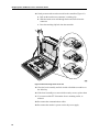
ET 350L3 monitor (hatch)
NEMA 4X hatch and extended hatch cover
NEMA 4X hatch gasket
Cable fitting components
Screws
Clear, flexible insulator
Instructions for installing the NEMA 4X hatch
The packing list for the KVM extender option appears on page 10.
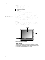
Standard features
The ET 350 monitor is an industrial flat-panel monitor with an integrated
MicroTouch NFI touch screen with TouchSurround. The monitor is
designed for rugged use in demanding industrial applications. The
standard features of the ET 350 monitor are described below.
Display
The display is an Active Color 15-inch Thin Film Transistor (TFT),
Liquid-Crystal Display (LCD) and is capable of 1024 × 768 XGA
resolution and up to 16.7M (million) colors.
Figure 1: 3M Dynapro ET 350 monitor
Touch screen
The monitor’s MicroTouch NFI touch screen consists of a chemically
strengthened glass surface with a controller that measures disturbances in
an electrostatic field near the surface of the screen.
6
Chapter 1: Introducing the ET 350 monitor
The touch screen consists of the display area and the TouchSurround
(Figure 1). Touches in the display area emulate the movements and actions
of a mouse, and you can use your finger like a pointer. The TouchSurround
can emulate keys on a keyboard.
The MicroTouch NFI touch screen provides highly accurate and clear
optics, is extremely durable, and can be operated accurately with gloves.
The touch screen does not require realignment to maintain touch accuracy,
even with variations in temperature and humidity.
Software
Touch screen drivers for the ET 350 monitor are included on the floppy
disks that came with the monitor. The software supports:
Windows XP Professional operating system
Windows 2000 Professional operating system
Windows NT 4.0 operating system
Windows 98 and Windows 95 (Windows 9X) operating systems
For details on installing the touch screen drivers and utilities, see “Step 5:
Install software and import TouchSurround files” starting on page 22.
Backlights
The life expectancy of the backlights is about 35,000 hours.
If the host computer is running Windows XP, 2000, or 98 operating
systems, you can extend the life of the monitor’s backlights by using the
operating system’s energy saver. For details, see “Backlights saver” on
page 25.
For information on replacing the backlights, contact 3M Touch Systems
customer service (see “Contacting 3M Touch Systems” on page 3).
7
3M Dynapro ET 350 Monitor User’s Installation Guide
Distinctive features
of each model
All ET 350 monitor units have the standard features described above. The
distinctive features of each model are described below and summarized in
Table A.
ET 350R monitor (NEMA 4X panel gasket)
The ET 350R monitor has a UL Recognized component mark. It comes
with a gasket that mounts between the monitor and a wall or panel
(Figure 2).
Figure 2: NEMA 4X panel gasket (comes with ET 350R)
The ET 350R monitor is suitable for Pollution Degree 3 environments if
installed and tested with the panel gasket in an enclosure that meets
NEMA 4X/IP66 ratings. If the ET 350R monitor is not mounted in such an
enclosure or mounted without the gasket, the unit is suitable for Pollution
Degree 2 environments.
ET 350L2 monitor (no gasket or hatch)
The ET 350L2 monitor comes with neither a gasket nor a hatch. This
model is UL Listed for Pollution Degree 2 environments and can perform
as a stand-alone unit in a Pollution Degree 2 environment.
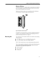
ET 350L3 (NEMA 4X hatch)
The ET 350L3 monitor comes with a NEMA 4X hatch (and extended hatch
cover) to seal both communication and power connections (Figure 3).
When properly installed with the materials supplied, the hatch provides a
NEMA 4X/IP66 seal on all sides and the monitor is UL Listed for
Pollution Degree 3 environments.
The ET 350L3 monitor may be used as a stand-alone unit in Pollution
Degree 3 environments.
8
Chapter 1: Introducing the ET 350 monitor
Figure 3: NEMA 4X hatch and extended cover (comes with ET 350L3)
Table A: Summary of features of each ET 350 model
Model
Distinctive features
ET 350R
•
•
This model comes with:
• Panel gasket
• Screws and washers
• Power cable
• Installation instructions
•
Note: On-site inspection is required
to verify pollution degree suitability
of the ET 350R and that the
installation complies with federal
and local electrical codes.
•
ET 350L2
•
This model comes with:
• Power cable
•
This model does not come with
gasket or hatch.
UL Recognized component mark.
NEMA 4X/IP66 rating for a panel
mount application.
Monitor suitable for Pollution
Degree 3 environments if
installed and tested with panel
gasket in an enclosure that meets
NEMA 4X/IP66 rating.
Suitable for Pollution Degree 2
environments if not mounted or if
mounted without the supplied
gasket.
UL Listing mark for Pollution
Degree 2 environments.
Monitor can perform as a standalone unit in a Pollution Degree 2
environment
(No on-site inspection required).
ET 350L3
This model comes with:
• NEMA 4X hatch (and extended
hatch cover)
• Screws and fitting components
• Installation instructions
•
•
•
UL Listing mark for Pollution
Degree 3 environments
NEMA 4X/IP66 rating
Monitor can perform as a standalone unit in a Pollution Degree 3
environment.
(No on-site inspection required).
Note: IEC and stripped power cables are available from 3M Touch Systems for
both North American and European applications. For more information on
power cables, see “Step 3: Connect to power supply” in Chapter 2, page 16.
9
3M Dynapro ET 350 Monitor User’s Installation Guide
Options
There are three types of options that may be ordered for the ET 350
monitor (not including mounting options, which are discussed on page 11):
Keyboard, video, and mouse (KVM) extender (single or dual) option
Fixed field wiring
The 3M Dynapro Moisture Deflector
Table B summarizes the options that are available for the ET 350 monitor
models.
Table B: Options available for ET 350 monitor models
Monitor
Model
KVM
extender
(single)
KVM
extender
(dual)
Field
wiring
Moisture
deflector
ET 350R
Option
Option
Option
Option
ET 350L2
Option
Option
n/a
Option
ET 350L3
Option
Option
Standard
Option
KVM extender (single or dual) option
The ET 350 monitor may come with a keyboard, video, and mouse (KVM)
extender option that allows the monitor to be located as much as 1000 feet
(300 meters) from the host computer.
Packing list for KVM extender option
If you ordered the ET 350 monitor with the KVM extender option, your
package should include:
KVM local device
KVM remote device (built into the housing of the ET 350 monitor)
Serial cable
Combination keyboard, video, and mouse cable to connect the local
unit to the host computer
KVM extender manufacturer’s manual
For more information on the KVM extender, see installation instructions
in Appendix B.
Fixed field wiring
Fixed field wiring is an option for the model that comes with a NEMA 4X
panel gasket (ET 350R monitor) and is standard for the model that comes
with a NEMA 4X hatch (ET 350L3 monitor). Fixed field wiring is not
available for the ET 350L2 monitor.
For more information on field wiring, see “AC power supply with fixed
field wiring (ET 350R monitor and ET 350L3 monitor only)” on page 17.
10
Chapter 1: Introducing the ET 350 monitor
Moisture Deflector
The Moisture Deflector is a durable plastic component that surrounds the
touch screen display of the monitor and offers protection to the monitor
from moisture that might collect on the unit.
The Moisture Deflector option can be supplied only when ordering an
ET 350 monitor. It cannot be added to the monitor later.
Figure 4: Moisture Deflector option
For guidelines on mounting the ET 350 monitor with Moisture Deflector,
see page 29. For information on handling and maintaining the ET 350
monitor with Moisture Deflector, see page 34.
Mounting kits
Two of the three ET 350 monitor models come with their own mounting/
sealing equipment:
ET 350R monitor comes with a NEMA 4X panel gasket
ET 350L3 monitor comes with a NEMA 4X hatch
The ET 350L2 monitor does not come with mounting/sealing materials.
There are three optional mounting kits available from 3M Touch Systems
for use with the ET 350 monitor. Each kit comes with its own set of
instructions for mounting and sealing the unit:
Boom mount kit
Rack mount kit
Desktop kit
11
3M Dynapro ET 350 Monitor User’s Installation Guide
Table C summarizes the mounting possibilities for each of the ET 350
monitor models.
Table C: Mounting possibilities for ET 350 monitor models
Monitor
Model
NEMA
hatch
NEMA
panel
Desktop
stand
Rack
mount
Boom
mount
ET 350R
Option
Standard
Option
Option
Option
ET 350L2
n/a
n/a
Option
n/a
n/a
ET 350L3
Standard
n/a
Option
n/a
n/a
For more information about the mounting kits, see “Step 8:
Mount monitor” on page 28.
12
CHAPTER 2
Installing the monitor
About the chapter
This chapter provides pre-installation recommendations and step-by-step
instructions for installing the ET 350 monitor.
Installation
summary
These steps outline a typical installation procedure for the ET 350 monitor.
While most installations will follow these steps, your specific installation
may differ.
Here is a summary of the steps for installing the ET 350 monitor:
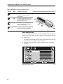
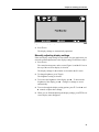
1. Connect video signal cable
2. Connect serial cable
Important
If your ET 350 monitor includes a KVM extender option, follow the steps in
Appendix B and then complete the remaining steps in this chapter.
3. Connect to power supply
4. Adjust display settings
5. Install touch screen software and import TouchSurround files
6. Set backlights saver and safe touch
7. Close enclosure and (if applicable) close hatch
8. Mount monitor
Warning
To reduce the risk of fire or electric shock which could result in serious personal
injury or death:
• Install the ET 350 monitor close to the power source so the unit can be easily
and quickly disconnected. For permanently connected equipment, a readily
accessible disconnect device must be incorporated in the fixed wiring.
• Any servicing or other procedures not described in this manual are to be
performed only by 3M Touch Systems service personnel.
13
3M Dynapro ET 350 Monitor User’s Installation Guide
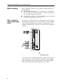
Before installing
Before beginning to install the ET 350 monitor, consider the following
recommendations:
Get the latest video driver for your host computer’s video adapter
card. To find out if your driver is the most current one, check the web
site of the video adapter’s manufacturer.
Check the host computer’s monitor settings to make sure that the
resolution is not greater than 1024 x 768.
Step 1: Connect
video (VGA) signal
cable
The video (VGA) signal cable carries a video signal from the computer’s
video adapter to the monitor. The ET 350 monitor comes with a standard
15-pin VGA cable that plugs into the monitor’s female connector. The
standard cable length is 6 feet. There are 25-foot and 50-foot cable options
available.
Figure 5: Connectors: ET 350 monitor (without KVM extender)
You may choose to use a standard signal cable or make a cable using the
“Video signal cable connector” pin-out in Appendix C. When making a
cable, 3M Touch Systems recommends you use a high-quality shielded
cable such as Belden cables 1417B, 1418B, 1522A, or 1826A.
14
Chapter 2: Installing the monitor
Important
•
To reduce the risk of voiding FCC and CE compliance and reducing the
performance of the ET 350 monitor, when making your own cable, reduce the
sensitivity of the ET 350 monitor to electrical and radio frequency noise by
connecting the cable shield to the connector shield (360º shield) on both
ends of the cable.
•
Before attaching or removing communication cables, disconnect power to
the ET 350 monitor.
To connect the video signal cable, follow these steps:
1. If the monitor has a hatch, the hatch must be open to access
connectors. Remove the four #6-32 Phillips screws affixing the hatch
to the monitor and open the hatch cover. For an illustration of the
locations of these screws, refer to Figure 13 on page 38.
2. Connect one end of the video signal cable to the VGA signal
cable connector on the side of the monitor.
3. Tighten the screws on the signal cable.
4. Connect the other end of the signal cable to the video adapter port on
the computer.
5. Tighten the screws of the signal cable to ensure proper connection.
6. After connecting the video signal cable to the monitor and computer,
make sure you have the latest video drivers for the video adapter. You
may be able to download the most recent drivers from the video
adapter manufacturer’s web site.
Step 2:
Connect serial
cable
The ET 350 monitor uses a 9-pin COM port for touch screen
communication with the host computer. The standard length of the serial
cable is 6 feet. There are 25-foot and 50-foot cable options available.
Use a standard cable or make one using the “Serial port RS-232C
connector” in Appendix C. Note that the pin-out presents the ET 350
monitor as a Data Communication Equipment (DCE) device so that a
“straight-through” cable can be used.
To connect the serial cable:
1. If the monitor has a hatch, make sure that the hatch is open (it
should have been opened when connecting the video cable). The
hatch must be open to access connectors.
2. Connect one end of the serial cable to the serial cable connector on
the side of the monitor.
15
3M Dynapro ET 350 Monitor User’s Installation Guide
Important
To reduce the risk of voiding FCC and CE compliance and reducing the
performance of the ET 350 monitor, when making your own cable, reduce the
sensitivity of the ET 350 monitor to electrical and radio frequency noise by
connecting the cable shield to the connector shield (360º shield) on both ends of
the cable.
3. Connect the other end of the serial cable to the serial port on the
computer.
4. Tighten the screws of the serial cable to ensure proper connection.
Step 3:
Connect to power
supply
The ET 350 monitor can be connected to an AC power supply in two ways:
with a standard AC power cable or with fixed field wiring.
Standard AC power supply
Use an AC power cable that is appropriate for the power scheme in your
country or region:
For applications in Europe, use a harmonized AC power cable. The
universal power supply of the ET 350 monitor automatically senses
the voltage from the external source and, within the range 115 to 230
VAC, 50 to 60 Hz, supplies the appropriate power without requiring
any adjustment.
For North American applications, use a standard AC power cable.
Both types of cable are available from 3M Touch Systems and come with
either an IEC connector or terminal strip wiring.
Warning
To reduce the risk of fire or electric shock which could result in serious personal
injury or death:
• Install the ET 350 monitor close to the power source so the unit can be easily
and quickly disconnected. For permanently connected equipment, a readily
accessible disconnect device must be incorporated in the fixed wiring.
• Wiring installation should be done by a licensed journeyman electrician and
must comply with federal and local electrical codes.
Important
Before attaching or removing communication cables, disconnect power to the
ET 350.
16
Chapter 2: Installing the monitor
To connect the AC power cable:
1. If the monitor has a hatch, make sure that the hatch is open (it
should have been opened when connecting the video cable). The
hatch must be open to access connectors.
2. Connect the power cable to the socket on the side of the monitor.
3. Connect the other end of the cable to a standard 15-ampere (or less)
branch circuit.
AC power supply with fixed field wiring
(ET 350R monitor and ET 350L3 monitor only)
Warning
•
To reduce the risk of fire or electric shock which could result in serious
personal injury or death, wiring installation should be done by a licensed
journeyman electrician and must comply with federal and local electrical
codes.
•
To reduce the risk of electric shock which could result in serious personal
injury or death, provide adequate strain relief for all communication and power
cables.
To connect the power supply with fixed field wiring, follow these steps:
1. Make sure the AC power supply is disconnected at its source.
2. Strip about 1/8-inch (3 mm) of insulation from the end of the neutral,
ground, and line wires.
Warning
To reduce the risk of fire or electric shock which could result in serious personal
injury or death, when connecting power with fixed field wiring, the power cable
must be double insulated. A clear, flexible insulator (supplied) must cover the
portion of the cable that is not double insulated when connecting to a terminal
strip connector.
3. Measure and, if necessary, cut the clear, flexible insulator (supplied)
so that it will cover the unjacketed portion of the power cable and
overlap the jacketed portion by at least one inch.
4. Slide the insulator up the power cable.
5. Insert the stripped end of the AC power cable wire (neutral) into the
terminal strip’s side connector (Figure 6).
- N/L2 NEUTRAL
-
GROUND
- L/L1 LINE
Figure 6: Connecting AC power cable wires to connectors
17
3M Dynapro ET 350 Monitor User’s Installation Guide
6. Using a 1/8-inch flathead screwdriver, turn the terminal block’s screw
clockwise until the neutral cable wire is firmly attached to the ET 350
monitor.
7. Repeat (5) and (6) for the ground and line cable wires and then
tighten the screws on the terminal block to a torque of 10 inchpounds.
8. Fasten a cable tie around the three wires at about one inch from the
terminal block (Figure 7).
Cable tie
Insulator
Cable tie
(inside insulator)
Terminal block
32531
Figure 7: Terminal connection for AC power (ET 350R, ET 350L3 monitors)
and for DC power
9. Make sure that one end of the insulator is flush with the terminal
connector and the other end overlaps the power cable jacket by at
least one inch.
10. To prevent the insulator from moving, secure the insulator to the
chassis of the monitor using a cable tie or other equivalent securing
device.
DC power supply (option)
To connect the ET 350 Monitor to DC power supply, follow these steps:
1. Make sure that the DC power supply is disconnected at its source.
2. Strip about 1/8-inch (3 mm) of insulation from the end of the
negative, positive, and ground wires.
3. Measure and, if necessary, cut the clear flexible insulator (supplied)
so that it will cover the unjacketed portion of the power cable and
overlap the jacketed portion by at least 1 inch.
4. Slide the insulator up the power cable.
5. Insert the DC- cable wire into the side connector of the terminal strip
(Figure 8).
18
Chapter 2: Installing the monitor
.
Figure 8: Connecting DC power cable wires to connectors
6. Using a 1/8-inch flathead screwdriver, turn the screw on the terminal
strip clockwise until the negative cable wire is firmly attached.
7. Repeat steps (5) and (6) for the “ground” and DC+ cable wires and
then tighten screws on the terminal block to a torque of 10 inchpounds.
8. Fasten a cable tie around the three wires at about one inch from the
terminal block (Figure 7).
9. Make sure that one end of the insulator is flush with the terminal
connector and the other end overlaps the power cable jacket by at
least 1 inch.
10. To prevent the insulator from moving down the cable, secure the
insulator to the chassis of the monitor by using a cable tie or other
equivalent securing device.
11. Connect power to the DC power cable at is source.
Step 4:
Adjust display
settings
Open the enclosure
To access the monitor’s controls, you must open it. To open the enclosure:
1. Put on an electrostatic discharge grounding wrist strap.
Important
To prevent damage from electrostatic discharge (ESD), wear a grounding wrist
strap when working with electronic components inside the enclosure. Follow the
instructions that come with the wrist strap. If a grounding wrist strap is not
available, touch a grounded metal object to discharge any static from your body.
2. Make sure that the power supply for the monitor is connected.
3. Open the monitor enclosure.
If your unit has security screws on the back of the bezel, remove
them with the appropriate screwdriver (the locations of the security
screws are shown in Figure 13 on page 38).
Apply a 5/32-inch (4 mm) Allen key to the latch screw on the top of
the enclosure. Turn the key counterclockwise ¼ turn, or until you
feel the unit opening.
It is not necessary to fully open the enclosure to operate display controls.
With the enclosure slightly ajar, you can access the display-setting controls
(located on the back of the monitor’s display, near the top). Table D
summarizes the functions of each on-screen control:
19
3M Dynapro ET 350 Monitor User’s Installation Guide
Table D: Summary of on-screen display controls
Symbol
Name
Function of the control
Menu
To start up the on-screen display
menus and to move through the
menu options.
Left
To move through main menu icons
(PC, OSD, Utility, and Auto) and to
decrease setting values.
Right
To move through main menu icons
(PC, OSD, Utility, and Auto) and to
increase setting values.
Exit
To exit the on-screen display menus.
Changes are saved automatically.
Display controls inside ET 350 monitor enclosure
Auto display setup
Run the auto display setup before manually adjusting individual display
settings. Auto display setup sets pre-programmed optimal display settings.
1. Press 1 once.
The display control menu appears on the screen and the PC icon at the
top of the on-screen display is selected (Figure 9).
2. Using the on-screen display controls, select the “Auto” menu item
(Figure 10).
Figure 9: PC menu options
20
Chapter 2: Installing the monitor
Figure 10: Auto display setup
3. Press 1 once.
The display settings are automatically optimized.
Manually adjusting display settings
If the auto display setup settings are not suitable for your application, you
can make manual adjustments to the display settings. Follow these steps:
1. Press 1 once.
The control menu appears on the screen (Figure 9) and the PC icon at
the top of the on-screen display is selected.
The display settings for the monitor are located in the PC menu.
2. To change brightness, press
1 again.
The brightness setting is selected.
3. To increase the brightness of the display, press
. To decrease the
brightness of the display, press . Changes to settings are saved
automatically.
4. To move through the display setting options, press 1. Use the
controls to adjust other settings.
and
5. When you are finished adjusting the display settings, press 2. The on-
screen display menu disappears.
21
3M Dynapro ET 350 Monitor User’s Installation Guide
Other on-screen display options
The most commonly used on-screen display options are those that appear
under the PC and Auto icons. Other on-screen options that can be set using
the controls are summarized below.
OSD (on screen display) menu
The settings in the OSD menu permit you to change the position and
appearance of OSD menus, the duration of a display before timeout, and
the language (English or Korean) of the OSD menus.
By increasing or decreasing the value of H-Position, for example, the OSD
menus can be shifted left or right on the display.
Utility menu
The settings in the Utility menu allow you to reset display settings to the
monitor manufacturer’s display setting defaults and to get information on
the display’s current resolution and frequency. Some units allow the user
to turn the display’s power management system (DPMS) on or off (the
default setting is “on”). For the ET 350 monitor, the DPMS should not be
turned off. For ET 35X monitors with heater, see installation instructions
that come with heater units regarding DPMS settings.
Warning
To reduce the risk of electric shock or mechanical impact which could result in
serious personal injury or death, if your ET unit has a display power management
system (DPMS) that is configurable from the display’s on-screen utility menu, do
not turn off the DPMS.
Note: The Dynamic Brightness control in the Utility menu is not
adjustable with the ET 350 monitor and so that menu item is dimmed.
Step 5:
Install software
and import
TouchSurround
files
Installing touch screen software
To install the touch screen drivers and utilities for the ET 350 monitor,
follow the instructions below that correspond to the operating system
running on the host computer. The ET 350 monitor currently supports
Windows XP Professional, Windows 2000 Professional, Windows NT
4.0, and Windows 9X operating systems.
Installing the driver for Windows XP/2000 operating systems
To install touch screen software for Windows XP or Windows 2000
operating systems:
1. Find the floppy disk that includes the driver for Windows XP/2000
operating systems, insert it in the disk drive, and browse the floppy
disk to find the file named setup.exe.
2. Open setup.exe.
The installation Welcome window appears.
22
Chapter 2: Installing the monitor
3. Follow the screen prompts to install the driver and then follow the on-
screen instructions of the Setup Wizard.
Note: When the Baseline dialog box appears, select Skip. When the
Linearization Data Download dialog box appears, select Skip.
Baseline and linearization data are built into the monitor at the
factory.
4. When the Setup Wizard finishes, an Install Successful window
appears.
Installing the drivers for Windows NT 4.0 and Windows 9X
operating systems
To install the touch screen software for Windows NT 4.0 and Windows 9X
operating systems, follow these steps:
1. Find the floppy disk that includes the drivers for Windows NT 4.0 and
Windows 9X operating systems, insert it in the disk drive, and browse
the floppy disk to find the file named install.exe.
2. Open install.exe.
The installation Welcome window appears.
3. Choose to install the driver and then follow the on-screen prompts to
install the driver.
When the software is installed, you will be prompted to restart.
Important
For Windows 98 operating system only: Turn off the Advanced Configuration
and Power Interface (ACPI). If the Windows 98 operating system ACPI feature is
not turned off, the COM port may not be accessible after re-booting the host
computer. For detailed instructions, refer to your Windows 98 operating system
user documentation.
4. For Windows 98 operating system only, turn off the Advanced
Configuration and Power Interface (ACPI). Follows these steps:
a. From the Windows operating system Start menu, select Settings,
then select Control Panel, and then open System.
b. Click the Device Manager tab, then open System Devices, and
then right-click ACPI BIOS and click Properties. A dialog box
appears.
c. Click the Driver tab, then click Update Driver, and then click
Next.
d. Click Display a list of all the drivers, then click Next, and then
click Show all hardware. A dialog box appears.
e. From the Manufacturers options (on the left side of the dialog
box), select Standard System Devices and from the Models
options (on the right), select PCI Bus, and then select Next.
23
3M Dynapro ET 350 Monitor User’s Installation Guide
f. Click Yes in reply to the question: Are you sure you want to use
this driver? The Update Device Driver Wizard appears.
g. Insert your CD-ROM for the Windows 98 operating system. (If
the CD-ROM welcome page appears, close it so you can see the
Wizard dialog box.)
h. Click Next in the Wizard dialog box and, after a message appears
confirming that the Windows operating system has finished its
task, click Finish.
i. Click Yes when the System Settings Change box appears asking if
you want to restart your computer.
j. After restarting the computer, confirm that the driver and
controller are communicating.
Importing standard TouchSurround definitions
Windows XP/2000 operating system
To import the standard TouchSurround definition for Windows XP and
Windows 2000 operating systems, follow these steps:
1. Find the button definition file 350.reg on the floppy disk with the
driver for Windows XP/2000 operating systems and copy it to the
hard drive of your host computer.
2. Double-click the 350.reg file.
A dialog box appears asking whether you want to add the
TouchSurround definition file information to the registry.
3. Select Yes.
A dialog box appears verifying that the file transfer has occurred.
4. Select OK.
5. Open the Configuration Utility dialog box and select TouchSurround.
The TouchSurround button definition dialog box appears.
6. Select OK.
The Configuration Utility dialog box re-appears. The standard button
definition file takes effect immediately. It is not necessary to reboot.
Windows NT 4.0/9X operating systems
The standard TouchSurround definition for Windows NT 4.0 and
Windows 9X operating systems is imported when installing the driver. If
you can’t find the TouchSurround definition file, you may need to reinstall
the software. Refer to the software guide appropriate for your operating
system (see “Software guides” on page 2).
24
Chapter 2: Installing the monitor
To import the standard TouchSurround definition for Windows NT 4.0 and
Windows 9X operating systems, follow these steps:
1. Select the Windows Start button, select Programs, and then select
Command Prompt.
2. At the command prompt, type
CD\TOUCH\NT for Windows NT
CD\TOUCH\W9X for Windows 9X
3. Type TOUCHINI /i350.ini
where 350.ini is the standard button definition file.
(Note: There is a space between TOUCHINI and the forward slash.)
The standard TouchSurround button configuration takes effect the next
time you start Windows NT 4.0 or Windows 9X operating systems.
Customizing drivers
Some of the driver features that can be customized include double touch
settings, touch screen sensitivity, and beep on touch. For instructions on
how to customize driver features, refer to the appropriate software guide
(see “Software guides” on page 2).
Step 6: Set
“backlights saver”
and “safe touch”
Backlights saver
You can extend the life of the monitor’s backlights (and conserve power)
by setting the host computer’s energy saver to “turn off the monitor” after
a specified number of minutes of inactivity. The energy saver (which is, in
effect, a backlights saver) is adjusted in the Display Properties dialog box
of Windows XP, 2000, and 9X operating systems.
Windows NT 4.0 operating system does not have an energy saver, so if the
host computer is running with Windows NT 4.0 operating system, the
backlights will be on whenever the unit is powered up (even if the
Windows NT 4.0 operating system screen saver is set to display a blank
screen).
Safe touch
This setting changes the way the touch screen responds when the user
touches the screen to reactivate the monitor following a period when the
backlights have been off.
With a safe touch setting applied, the user will not accidentally activate a
touch screen button on the part of the screen that is touched.
25
3M Dynapro ET 350 Monitor User’s Installation Guide
If the ET 350 monitor is running an application or is in a setting in which
unintentionally activating a button on the touch screen might have harmful
consequences for people or equipment, 3M Touch Systems recommends
creating a “safe touch” setting.
Warning
To reduce the risk of electric shock or mechanical impact which could result in
serious personal injury or death:
• Apply a “safe touch” setting, especially if the monitor is running an application
or is in a setting where safety is a concern.
•
Do not use a third party screen saver that may affect the “safe touch” setting
and could in turn cause connected peripheral equipment to start or stop
inadvertently.
The procedure for applying a safe touch setting differs depending on the
operating system.
Safe touch for Windows XP/2000 operating systems
To apply a safe touch setting with Windows XP and 2000 operating
systems, follow these steps:
1. Close all Windows operating system applications and then open the
Display Properties dialog box (for instructions on how to open
Display Properties, refer to your operating system’s help file).
2. Select the Screen Saver tab.
3. In the screen saver section of the dialog box, enter in the “Wait” box
the number of minutes that you want to elapse from the last time the
screen is touched to when the screen saver is activated.
4. In the energy saver section of the dialog box, select Power.
The power dialog box appears (called Power Scheme in
Windows XP; called Power Options Properties in Windows 2000).
5. In the “Turn off monitor” pull-down menu, set the number of minutes
that will elapse from the last time the screen is touched to when the
energy saver is activated. The period chosen must be at least one
minute greater than the time you set (in step 3, above) for the screen
saver.
Warning
To reduce the risk of electric shock or mechanical impact which could result in
serious personal injury or death, set the “safe touch” setting correctly, with the
number of minutes entered for the Windows operating system energy saver
being at least one minute greater than the time entered for the Windows
operating system screen saver.
26
Chapter 2: Installing the monitor
6. Select OK.
7. If your ET unit has a display power management system (DPMS),
that is configurable from the display’s on-screen menu options, make
sure that it is turned on. For details on how to check DPMS, see
“Utility menu” on page 22.
Safe touch for Windows 9X operating system
To apply a safe touch setting with a Windows 9X operating system, follow
these steps:
1. Close all Windows operating system applications, then open the
Display Properties dialog box (for instructions on how to open
Display Properties, refer to your operating system’s help file).
2. Select the Screen Saver tab.
3. In the screen saver section of the dialog box, enter in the “Wait” box
the number of minutes that you want to elapse from the last time the
screen is touched to when the screen saver is activated.
4. In the energy saver section of the dialog box, select Settings.
The power management dialog box appears.
5. In the “Turn off monitor” pull-down menu, set the number of minutes
that will elapse from the last time the screen is touched to when the
energy saver is activated. The period chosen must be at least one
minute greater than the time you set (in step 3, above) for the screen
saver.
Warning
To reduce the risk of electric shock or mechanical impact which could result in
serious personal injury or death, set the “safe touch” setting correctly, with the
number of minutes entered for the Windows operating system energy saver
being at least one minute greater than the time entered for the Windows
operating system screen saver.
6. Select OK.
7. If your ET unit has a display power management system (DPMS),
that is configurable from the display’s on-screen menu options, make
sure that it is turned on. For details on how to check DPMS, see
“Utility menu” on page 22.
Safe touch for Windows NT 4.0 operating system
Windows NT 4.0 operating system does not have an energy saver, so it is
not necessary to apply a safe touch setting with this operating system.
27
3M Dynapro ET 350 Monitor User’s Installation Guide
Step 7:
Close enclosure
and hatch
Close enclosure
When you are finished adjusting the display settings, close the enclosure:
1. Close the bezel assembly and lock the latch screw with the Allen key.
2. If applicable, replace the four security screws. Tighten the screws to a
torque of 10 inch-pounds.
Close hatch
To close the hatch, insert the four #6-32 Phillips screws loosely. Using a
No. 1 Phillips torque screwdriver, gradually tighten diagonal pairs of
screws until all are equally tight at a torque of 7 inch-pounds. This may
require about three rounds of tightening.
Step 8:
Mount monitor
Two of the three ET 350 monitor models come with their own mounting/
sealing equipment and mounting instructions (and the instructions are also
available for download from www.3Mtouch.com):
ET 350R monitor with a NEMA 4X panel gasket
ET 350L3 monitor with a NEMA 4X hatch
The ET 350L2 monitor does not come with mounting materials, but there
are optional mounting kits available from 3M Touch Systems (see below).
For details of the features of the three ET 350 monitor models, see
“Distinctive features of each model” on page 8.
Optional mounting kits
Each mounting kit comes with its own set of installation instructions (also
available for download from www.3Mtouch.com):
Boom mount kit allows the monitor to be mounted on a post, boom or
suspension arm with a NEMA 4X sealed hatch or extended hatch.
Rack mount kit makes it possible to mount the monitor on a standard
19-inch industrial rack.
Desktop stand kit is a two-piece desktop stand option that allows the
monitor to be set on a desk, bench, or table top.
A security hardware kit, also available from 3M Touch Systems, includes
four security screws and a security screwdriver that make it possible to
lock the back of the ET 350 monitor enclosure. Once the security screws
have been inserted, the monitor cannot be opened from the front by an
unauthorized user.
Warning
To reduce the risk of electric shock which could result in serious personal injury
or death, before removing the ET 350 monitor from its mounting, disconnect
power to the unit.
28
Chapter 2: Installing the monitor
Important
If security screws are used, the operator will not be able to access the enclosure
without a security screwdriver. This means that the operator may be unable to
perform such tasks as changing display settings.
The locations for attaching the security screws are shown in Figure 13 on
page 38.
Mounting the ET 350 monitor with Moisture Deflector
The ET 350 monitor with Moisture Deflector comes with four sealing
screws fastened to the back of the unit. 3M Touch Systems recommends
that if you need to remove the sealing screws to access the enclosure, you
re-attach the screws after closing the enclosure.
The ET 350 monitor with Moisture Deflector must be mounted
vertically—with no more than 10 degrees variance from vertical—for the
Moisture Deflector to operate. As long as the 10 degree rule is observed, it
is possible to mount the monitor with the Moisture Deflector using any of
the mounting kits described above.
29
CHAPTER 3
Maintaining the monitor
About the chapter
This chapter describes how to:
Clean the touch screen and enclosure
Replace backlights
Replace the fuse
Check gaskets for damage or improper functioning
Maintain the ET 350 monitor with Moisture Deflector
Warning
To reduce the risk of electric shock which could result in serious personal injury
or death, do not open the power supply in the ET 350 monitor. It contains
hazardous voltages. The power supply has no user-serviceable parts or
adjustments inside.
Cleaning
Cleaning the touch screen
When cleaning the front surface of the NFI touch screen, use any chemical
that does not corrode glass. The touch screen will function, even if its front
surface is pitted or damaged by a chemical.
Caution
To reduce the risk of minor or moderate injury from contact with cleaning
solutions or fluids, through means such as ingestion and skin contact, refer to
the cleaner manufacturer’s material safety data sheet and follow all instructions
and recommendations.
Important
Clean the back of the touch screen (the surface that is inside the touch screen
and is exposed to the graphic underlay) using only cleaning solutions and
materials designed for coated optics. The back of the touch screen is covered
with a coating that is easily damaged by commercial glass cleaners or a regular
cloth.
31
3M Dynapro ET 350 Monitor User’s Installation Guide
Cleaning the enclosure
Use a 50 percent solution of alcohol (ethanol or isopropanol) in water on a
cotton gauze pad or soft cotton cloth to clean the enclosure. Be sure to
apply the alcohol solution to the cloth only, not directly to the enclosure.
Warning
To reduce the risk of fire or explosion which could result in serious personal
injury or death, when using a flammable or combustible cleaning solution or
fluid on or near the ET 350 monitor, refer to the cleaner manufacturer’s material
safety data sheet and follow all instructions and recommendations.
Replacing
backlights
For information on replacing backlights for the ET 350 monitor, contact
3M Touch Systems customer service (see “Contacting 3M Touch
Systems” on page 3).
Replacing the fuse
The fuse holder is adjacent to the power socket of the ET 350 monitor.
Tools required
3/16-inch flat-blade screwdriver
No. 1 Phillips torque screwdriver (for ET 350L3 monitor)
Steps
To replace the fuse:
1. Disconnect power to the ET 350 monitor.
Important
Do not replace the fuse while the monitor is connected to its power supply.
2. If the monitor has a hatch, remove the four #6-32 Phillips screws
affixing the hatch to the monitor and then open the hatch cover. Once
the hatch is open, the fuse holder should be visible.
3. Locate the fuse holder. It is adjacent to the power cable connector (see
Figure 5 on page 14).
4. Insert an appropriate screwdriver into the fuse holder’s slot
(Figure 11).
Figure 11: Loosening fuse holder
32
Chapter 3: Maintaining the monitor
5. While gently pressing the fuse holder, turn the screwdriver
counterclockwise.
The fuse holder will pop out of the ET 350 monitor.
6. Remove the fuse holder with the fuse.
7. Detach the fuse from the fuse holder by pulling on it gently.
Figure 12: Removing fuse from fuse holder
Warning
To reduce the risk of fire or electric shock which could result in serious personal
injury or death, when replacing a fuse or other part, use a part of the same type
rating specified by 3M Touch Systems.
8. Replace the fuse. For fuse specifications, see “Fuses” on page 52.
9. Reinstall the fuse holder in the ET 350 monitor.
10. While gently pressing the fuse holder, turn the screwdriver clockwise.
11. If the monitor has a hatch, close the hatch cover (opened earlier):
Insert all screws loosely. Using a No. 1 Phillips torque screwdriver,
gradually tighten diagonal pairs of screws until all are equally tight at
a torque of 7 inch-pounds. This may require about three rounds of
tightening.
12. Re-connect power to the unit.
Checking gaskets
Follow these guidelines to check and clean the gaskets on your monitor:
Make sure there is no debris on gaskets that will prevent a seal.
If debris needs to be cleaned from gaskets, do so gently.
If gaskets are torn or damaged, return to 3M Touch Systems for
servicing.
33
3M Dynapro ET 350 Monitor User’s Installation Guide
Maintaining the ET
350 monitor with
Moisture Deflector
The Moisture Deflector is made of durable plastic and, like other
3M Dynapro components, is designed to function in rugged conditions.
It is not indestructible, however. Follow these guidelines to extend its life
and help ensure optimal performance:
Before starting the ET 350 monitor with Moisture Deflector, make
sure that the temperature is at least 0ºC.
Do not hang anything from the Moisture Deflector. Doing so may
cause it to perform poorly.
Before opening the enclosure of the ET 350 monitor with Moisture
Deflector, make sure that the unit is completely dry. If water has
collected on the top of the enclosure and is not removed before
opening it, moisture might run into the unit.
To open the unit, you will need to remove the four sealing screws
attached to the back of the unit. After closing the enclosure, re-attach
the sealing screws.
When handling the monitor, do not grasp it by the Moisture Deflector.
If it is necessary to ship the monitor for any reason, use the original
packing materials, if possible. When packing the unit, take care to
protect the Moisture Deflector from being damaged during shipping.
34
CHAPTER 4
TouchSurround and graphic
underlay
About the chapter
This chapter describes:
The function of the TouchSurround and graphic underlay
How to get a custom underlay
How to replace the underlay
Warning
To reduce the risk of electric shock which could result in serious personal injury
or death, do not open the power supply in the ET 350 monitor. It contains
hazardous voltages. The power supply has no user-serviceable parts or
adjustments inside.
About the
TouchSurround
The TouchSurround is the touch-sensitive area of the computer screen
around the LCD display (see Figure 1 on page 6). A graphic underlay is
located under the touch screen and it identifies buttons, touchable symbols,
pictures, and icons.
Standard TouchSurrounds
Standard TouchSurround layouts from 3M Touch Systems feature
predefined buttons that permit some keyboard functions (for example,
Enter) to be performed by touch. The functions of the buttons can be
changed by following instructions in the software guide appropriate for
your operating system (see “Software guides” on page 2).
Custom TouchSurrounds
Custom TouchSurrounds let you customize the user’s interface with the
monitor. You can change the number, size, and position of buttons, and
create icons or touchable graphics that suit your needs.
If you need a custom TouchSurround, you can order the monitor with a
custom TouchSurround or you can replace the TouchSurround graphic
underlay later, as described in this chapter.
35
3M Dynapro ET 350 Monitor User’s Installation Guide
Creating your own graphic underlay
If you need a custom graphic underlay, it is recommended that you order
it from 3M Touch Systems, especially if the underlay will need to
withstand temperature and humidity extremes.
Important
For the TouchSurround graphic underlay to withstand the same temperature
and humidity extremes that the ET 350 monitor can withstand, you should not
attempt to create your own underlay. Instead, order your underlay from 3M
Touch Systems.
The monitor is designed to operate in temperatures from 32°F to 122°F
(0°C to 50°C), and with humidity up to 95% (non-condensing). If you do
not need this level of durability, you may choose to print the underlay
yourself. There are two possible methods:
Silk screen printing onto a clear, soft, matte finish polycarbonate
sheet. 3M Touch Systems recommends that you use a sheet that is
0.015 inches thick and printed on the “back” side (to prevent the
printed surface from touching the glass).
Inkjet or color laser printing onto paper or a plastic sheet. Avoid
having the printed surface in direct contact with the touch screen—
under certain conditions it could adhere to the glass. Laminate the
underlay with clear matte-finish plastic to prevent contact between
the printed surface and the glass.
With either method, make sure the surface in contact with the glass has a
matte finish to prevent the optical distortion known as Newton’s Rings.
After installing a new underlay, you will need to define new positions,
actions and functions for your buttons or icons. For instructions on doing
this, refer to the appropriate software guide (see “Software guides” on
page 2).
36
Chapter 4: TouchSurround and graphic underlay
Replacing a
TouchSurround
graphic underlay
What you will need
The rest of this chapter describes how to remove the graphic underlay that
came with your monitor and replace it with a new, custom underlay.
To do the tasks described in this section, you will need:
A clean, ESD-protected environment with a work bench.
Two people: one to replace the underlay and another to support the
monitor.
The following tools and materials:
5/32-inch (4 mm) Allen key (supplied with the monitor)
5/16-inch torque hex nut driver
Latex or cotton work gloves
Cleaning solution and cloths designed for cleaning coated optical
glass
Security screwdriver, if the enclosure is secured with security
screws
Important
To prevent damage from electrostatic discharge (ESD), wear a grounding wrist
strap when working with electronic components inside the enclosure. Follow
the instructions that accompany the wrist strap. If a grounding strap is not
available, touch a grounded metal object to discharge any static charge from
your body.
Opening monitor
To open the enclosure of the monitor:
1. Disconnect power to the ET 350 monitor.
Warning
To reduce the risk of electric shock which could result in serious personal injury
or death, before removing the ET 350 monitor from its mounting, disconnect
power to the unit.
2. It is recommended that the monitor be removed from its mounting
and brought to a clean work area:
a. Disconnect all communication connections from the monitor. For
more information about connections, see Chapter 2, starting at
page 13.
b. Remove the monitor from its mounting.
c. Lay the monitor on a flat surface. You may want to place foam
pads or other material underneath the unit to protect the front
surface of the touch screen and its bezel.
37
3M Dynapro ET 350 Monitor User’s Installation Guide
3. Put on an ESD grounding wrist strap if one is available. If a
grounding wrist strap is not available, touch a grounded metal object
to discharge any static charge from your body.
4. Open the enclosure.
If your unit has security screws on the back of the bezel, remove
them with a security screwdriver (the locations of the security
screws are shown in Figure 13).
Figure 13: Location of optional security screws
Apply a 5/32-inch (4 mm) Allen key to the latch screw on the top
of the enclosure. Turn the key counterclockwise ¼ turn, or until
you feel the unit opening.
5. Have one person support the enclosure in the open position during the
rest of this procedure so that the monitor does not tip.
38
Chapter 4: TouchSurround and graphic underlay
6. Carefully disconnect the touch screen tail connector from the
controller board (Figure 14).
a. Gently pull out the touch screen connector’s retaining clip with
two fingers.
b. Gently pull the touch screen tail from the controller and through
the ferrite block.
Figure 14: Disconnecting touch screen tail connector
39
3M Dynapro ET 350 Monitor User’s Installation Guide
7. Using a 5/16-inch torque hex nut drive, remove the four display panel
nuts and washers (Figure 15).
Figure 15: Removing display panel nuts and washers
40
Chapter 4: TouchSurround and graphic underlay
8. Carefully slide the display pan away from the threaded studs and lift
it to a vertical position, taking care not to damage the cables
connected to the components on the display pan (Figure 16):
a. Lift the hinge side of the display pan up from the threaded studs.
b. Slide the display pan away from the other two threaded studs.
c. Lift the display pan to a vertical position.
9. Have one person support both the display pan and the main enclosure
while the other person replaces the underlay.
The glass surface under the underlay marks easily. Do not touch or
scratch the glass while replacing the underlay. If you do touch the
glass and leave stains or fingerprints, clean it before you install the
new underlay.
Important
Clean the back of the touch screen (the surface that is inside the touch screen
and exposed to the graphic underlay) using only cleaning solutions and
materials designed for coated optics. The back of the touch screen is covered
with a coating that is easily damaged by commercial glass cleaners or a regular
cloth.
Figure 16: Sliding display pan out and lifting it
41
3M Dynapro ET 350 Monitor User’s Installation Guide
10. Remove the underlay in stages. The underlay is larger than the
opening in the sheet metal retaining frame. You can bend the
underlay, but do not tear or crease it.
To loosen the underlay from the glass surface, use a finger and push a
corner of the underlay towards the center of the glass. As the underlay
buckles and the corner comes into view, pull it up to clear the
retaining frame. Repeat at each corner until the underlay is free
(Figure 17).
Figure 17: Removing original underlay
11. Remove the custom underlay from its packaging and make sure it is
clean. If necessary, clean it with a cleaning solution and cloth
designed for cleaning coated optical glass.
42
Chapter 4: TouchSurround and graphic underlay
12. Being careful not to damage the new underlay, place it under the
retaining frame in stages: slide one corner in place under the retaining
frame, then bend the underlay and slide in the next corner. Continue
until the underlay is in place against the surface of the glass
(Figure 18).
Figure 18: Placing new underlay
13. Lower the display pan to its original position over the underlay and
secure it with the nuts that were removed earlier. Make sure you use
the washers with the nuts on the hinge side of the display pan.
Tighten the nuts to a torque of 10 inch-pounds.
43
3M Dynapro ET 350 Monitor User’s Installation Guide
14. Gently reconnect the touch screen tail to the controller (Figure 19):
a. Pull out the touch screen connector’s retaining clip.
b. Slide the touch screen tail through ferrite and insert it into the
connector.
c. Press the retaining clip back into the controller.
Figure 19: Reconnecting touch screen tail
15. Close the bezel assembly and lock it with a flat-blade screwdriver or
the Allen key.
16. If the bezel assembly was secured with security screws, replace them.
17. If you removed the ET 350 monitor from a mounting earlier, re-
mount it.
18. Re-connect the communications cables.
19. Re-connect the monitor’s power cord to the power supply.
44
CHAPTER 5
Troubleshooting
About the chapter
This chapter outlines problems that may occur when using the
3M Dynapro ET 350 monitor and suggests solution strategies. If problems
persist after following the applicable instructions in this chapter, contact
3M Touch Systems technical support (see page 3).
General problems
Problem
Solution
Video image is unsatisfactory.
•
•
•
No video image.
•
•
•
Adjust display settings (see
page 19).
Try reducing the refresh rate of your
graphic card’s output.
For monitors with KVM extender
option:
• Adjust focus and/or brightness
dials on the remote unit of the
KVM extender.
•
Consider adjusting KVM extender
cable-length jumpers (see page
57).
•
Refer to the “video” section of the
troubleshooting chapter in the
KVM extender manufacturer’s
manual.*
Make sure that the monitor is powered
up. Listen for the sound of a fan.
Check the video extension cables
(and, for units with the KVM extender
option, check the CAT5 interconnect
cable) to be sure that all connectors
are properly and securely attached.
Make sure that the host computer’s
monitor resolution is set for no higher
than 1024 x 768.
*Note: References to “serial device” in the KVM manufacturer’s manual denote
the “touch screen” of the ET 350 monitor.
45
3M Dynapro ET 350 Monitor User’s Installation Guide
Problem
Solution
ET 350 monitor does not power
up when plugged in.
Try the following:
1. Make sure that the power to the
monitor’s power cable is turned on.
2.
Make sure that the power to the host
computer’s power supply is turned on.
3.
Check that the power cord is properly
connected at both ends.
4.
Check the fuse (see “Replacing the
fuse” on page 32).
5.
Plug the power cable back into the
monitor and restore power to the
cable.
After manually aligning the
TouchSurround buttons,
alignment of the touch screen is
unsatisfactory.
•
Try downloading the standard
TouchSurround button definition file
(see “Importing standard
TouchSurround definitions” on
page 24) and then customize the
button definition files as required. For
instructions on customizing, refer to
the appropriate software guide (see
“Contacting 3M Touch Systems” on
page 3).
Touch screen not functioning.
•
Make sure that the touch drivers are
installed properly.
Read the touch screen driver error
messages (below) and follow the
applicable instructions.
•
Keyboard/mouse not functioning
for the ET 350 monitor with KVM
extender option.
•
Refer to the “keyboard/mouse”
section of the troubleshooting chapter
in the KVM extender manufacturer’s
manual.*
*Note: References to “serial device” in the KVM manufacturer’s manual denote
the “touch screen” of the ET 350 monitor.
46
Chapter 5: Troubleshooting
Touch screen
driver error
messages
The touch screen drivers can detect error conditions that are independent
of the operating system. If you see one of the following error messages,
please note the number displayed with it. This will help 3M Touch
Systems technical support staff to diagnose the problem (see page 3).
Error message
Solution
9002: Unable to
communicate with touch
controller. Check COM port
settings and cabling.
1.
Disconnect power to the controller.
2.
Double-check all connections between
the controller and the host computer.
3.
Re-connect power to the controller.
4.
Double-check COM port settings for all
peripheral devices and the controller.
5.
Ensure no other touch drivers are loaded.
6.
If the error message persists, call
3M Touch Systems for assistance.
•
When turning on the MicroTouch NFI
touch screen system, make sure that
nothing is touching the touch screen or
bezel.
If error persists after power-cycling with a
clean, untouched screen:
• There may be short circuits to the
touch controller or screen.
91xx: Touch controller
image error detected.
•
•
•
•
The touch screen connector may be
loose.
•
The touch screen or controller may
need servicing.
Double-check all connections between
the controller and the host computer.
If the error message persists, call
3M Touch Systems for assistance.
91xx: Unrecoverable
EEPROM failure detected
in touch controller. Touch
screen is inoperable.
Servicing is required.
•
Controller requires servicing. Call
3M Touch Systems for assistance.
91xx: Touch controller failed
RAM or ROM test. Touch
screen is inoperable.
Servicing is required.
•
Controller requires servicing. Call
3M Touch Systems for assistance.
47
APPENDIX A
Specifications
Enclosure and
cutout dimensions
Imperial
Metric
Enclosure
14.00" high × 16.30" wide
× 6.32" deep
355.60 mm high ×
414.02 mm wide ×
160.53 mm deep
Panel cutout
12.33" high × 14.36" wide
313.18 mm high ×
364.74 mm wide
Mounting
clearances
Rear 1"
Rear 25.4 mm
Weight
Standard: 20.5 lb.
With KVM extender: 21.3 lb
Standard: 9.3 kg
With KVM extender: 9.7 kg
Figure 20: Enclosure dimensions
49
3M Dynapro ET 350 Monitor User’s Installation Guide
6.685"
(169.80 mm)
30023_a
Figure 21: Cutout dimensions
50
Appendix A: Specifications
Display
specifications
Viewing area
11.97" (304.1 mm) horizontal
8.98" (228.1 mm) vertical
15" (381 mm) diagonal
Pixel format
1024 (horizontal)× 768 (vertical)
Type
Active Color TFT
Panel colors (up to)
16.7M
Contrast ratio
300:1 (typical)
Viewing angle (typical)
H ± 65°
V +50° to -60°
Backlights
4 CCFL
Backlight life
expectancy
35,000 hr (typical)
Brightness (typical)
250 cd/m2(typical)
Display modes
Mode
Chemical
resistance
Supported
operating systems
Resolution
VESA
Horizontal
frequency
(kHz)
Vertical
frequency
(Hz)
Pixel
clock
(MHz)
VGA
640 × 480
640 × 480
43.27
85.0
36.000
SVGA
800 × 600
800 × 600
53.67
85.1
56.250
XGA
1024 × 768
1024 × 768
68.67
85.0
94.500
The bezel provides resistance to user abuse and to most chemicals and
other substances. Contact 3M Touch Systems technical support for
guidelines on protecting the equipment from specific chemicals.
Windows XP Professional operating system
Windows 2000 Professional operating system
Windows NT 4.0 operating system
Windows 98 operating system
Windows 95 operating system
51
3M Dynapro ET 350 Monitor User’s Installation Guide
Communications
Port/
connector
Standard
monitor
Description
Touch screen interface to host
computer
Serial
RS-232C compatible asynchronous
serial port
9-pin female D-connector
Video interface to host
VGA
VGA signal cable port
15-pin female VGA connector
Analog RGB 0.7V p-p
TTL level SYNC
Monitor with
KVM extender
CAT5
Interconnection between KVM remote
and local units
Mouse and
keyboard
Two 6-pin mini-DIN female connectors
for keyboard and mouse output to
computer
Fuses
Type
AC power units
Suggested
manufacturers
1.0 A 250 VAC Type T
Littelfuse 215.001
Schurter 0001.2504
Wickman 1811100000
DC power units
4A 250V, Type T
Bussmann GDC-4A
Littelfuse 218004
AC power supply
AC power source
IEC connector or 3 terminal strip
Input range
115/230 VAC autoranging
Frequency
50/60 Hz
Input current
0.6A @ 115 VAC
0.6A@ 230 VAC
DC power supply
52
DC power source
3 terminal strip
DC power input
22-28 VDC (typically 24 VDC)
DC input current
2A
Appendix A: Specifications
Operating
conditions
Condition
Range
Operating
temperature
0°C to 50°C (32°F to 122°F)
Humidity
50°C, 5% to 95% non-condensing
Maximum operating
altitude
6,560 feet (2,000 meters)
Vibration
5 to 57 Hz 0.006 in peak displacement
58 to 2000 Hz 1.0 G acceleration
Shock
Acceleration: 15 G
Pulse duration: 11 ms
Non-operating
conditions
Condition
Range
Storage temperature
-25°C to 60°C (-13°F to 140°F)
Maximum storage
altitude
40,000 feet (12,192 meters)
Vibration
5 to 57 Hz 0.015 in peak displacement
58 to 2000 Hz 2.5 G acceleration
Shock
Acceleration: 30G
Pulse duration: 11 ms
Safety standards
UL 60950 (3rd
edition)
for Information Technology Equipment
EN 60950
Dust and moisture
resistance
CSA C22.2
No. 950-1995
for Information Technology Equipment via UL’s
C-UL certification
NEMA 250
Electrical Enclosures, Type 12, Type 4, Type 4X
IEC 529
Degrees of Protection Provided by Enclosures,
IP66
53
3M Dynapro ET 350 Monitor User’s Installation Guide
FCC compliance
This equipment has been tested and found to comply with the limits for a
Class A digital device, pursuant to Part 15 of the FCC Rules. These limits
are designed to provide a reasonable protection against harmful
interference when the equipment is operated in a commercial environment.
This equipment generates, uses, and can radiate radio frequency energy,
and if installed and used in accordance with the instruction manual, may
cause interference to radio communications. Operation of this equipment
in a residential area is likely to cause harmful interference, in which case
the user will be required to correct the interference at his own expense.
CE and EMC
emissions
compliance
This is a Class A product. In a domestic environment this product may
cause radio interference, in which case the user may be required to take
adequate measures.
The ET 350 monitor complies with the CE mark related to the Low
Voltage Directive 73/23/EEC as confirmed in the Declaration of
Conformity.
The ET 350 monitor complies with the CE mark related to the EMC
Directive 89/336/EEC as confirmed in the Declaration of Conformity.
Canadian
emissions
compliance
Electromagnetic
compatibility
immunity
standards
54
This Class A digital apparatus meets all requirements of the Canadian
Interference-Causing Equipment Regulations.
Cet appariel numerique de la classe A respecte toutes les exigences
due Reglement sur le material brouilleur du Canada.
Electromagnetic compatibility immunity standards
EN61000-6-2
ITE immunity
EN55024
Electrostatic discharge
EN61000-4-2
Radiated immunity
EN61000-4-3
Electrical fast transient
EN61000-4-4
Surge transient
EN61000-4-5
Conducted immunity
EN61000-4-6
AC sags and dropouts
EN61000-4-11
Appendix A: Specifications
Electromagnetic
emission standards
EN55022 Class A
ICES-003 Class A
FCC CFR 47, Part 15, Subpart B, Class A
C-Tick — Australia, New Zealand
Product
certifications
UL Information Technology Equipment — United States
ET 350R monitor (with panel gasket)
UL recognized component for Pollution Degree 3 environments if
installed and tested with panel gasket in an enclosure that meets NEMA
4X/IP66 rating.
UL recognized for Pollution Degree 2 environments if not mounted or if
mounted without the supplied gasket.
ET 350L2 monitor (without hatch and without panel gasket)
UL listed for Pollution Degree 2 environments.
ET 350L3 monitor (with NEMA 4X hatch)
UL listed for Pollution Degree 3 environments.
C-UL Information Technology Equipment — Canada
CE Information Technology Equipment — Europe
System software
Touch screen drivers emulate Microsoft mouse driver.
Utility to configure TouchSurround emulates 101-key enhanced
PC-compatible keyboard.
55
APPENDIX B
Installing monitor with
KVM extender
About this
appendix
This appendix provides instructions for installing the ET 350 monitor with
the keyboard, video, and mouse (KVM) extender option. For more
information about the KVM extender, refer to the manufacturer’s manual
that came with your ET 350 monitor.
The KVM extender option allows the monitor to be located up to 1000 feet
(300 meters) from the host computer. The KVM extender has a local unit
and a remote unit. The remote unit is built into the housing of the monitor.
Step 1:
Check and set KVM
settings
Cable-length jumpers
There are three cable-length jumpers on the remote unit of the KVM
extender’s circuit board, inside the monitor’s enclosure (Figure 22).
Figure 22: Enclosure of ET 350 monitor with KVM extender
57
3M Dynapro ET 350 Monitor User’s Installation Guide
These jumpers (JP3, JP4, and JP5) can be set to adjust equalization of the
monitor’s display to compensate for loss of image quality due to the signal
passing through a long cable.
Important
If the length of the cable running between the local and remote units is 655 to
1000 feet (200 to 300 meters), which is the default setting for the ET 350
monitor, the jumpers should not need adjusting.
To set the cable-length jumpers:
1. Put on an ESD grounding wrist strap.
Important
To prevent damage from electrostatic discharge (ESD), wear a grounding wrist
strap when working with electronic components inside the enclosure. Follow
the instructions that come with the wrist strap. If a grounding wrist strap is not
available, touch a grounded metal object to discharge any static from your
body.
2. Disconnect power from the ET 350 monitor.
3. Determine the length of cable between KVM local and remote units.
4. Set the cable-length jumpers as follows:
If the cable is this length
655 to 1000 feet
(200 to 300 meters)
Set the three cable-length jumpers like this
Default setting for ET 350 monitor.
330 to 655 feet
(100 to 200 meters)
0 to 330 feet
(0 to 100 meters)
58
Off
Appendix B: Installing monitor with KVM extender
If the length of cable between the local and remote units is near the
high end of one of the ranges and you are using high-resolution video
(1024 x 768), try setting jumpers for the next higher cable length.
This might help improve video compensation.
5. To fine-tune the display image after setting the jumpers, adjust the
Brightness and Focus rotary controls. The controls are on the KVM
remote unit inside the hatch of the ET 350 monitor (see Figure 23 on
page 61).
Keyboard and mouse control
The ET 350 monitor DIP-Switch SW1 on the KVM extender board is set
to off (see Figure 22). With this setting, the monitor user can take control
by pressing a key on the keyboard or by moving the mouse.
Important
The DIP-Switch default setting for the ET 350 is off. This is different from the
default setting that appears in the KVM extender manufacturer’s manual.
If you prefer that users not be able to take control simply by typing on the
keyboard, the DIP-Switch will need to be switched to the on position.
To change the DIP-Switch setting:
1. Put on an electrostatic discharge (ESD) grounding wrist strap.
Important
To prevent damage from electrostatic discharge (ESD), wear a grounding wrist
strap when working with electronic components inside the enclosure. Follow
the instructions that come with the wrist strap. If a grounding wrist strap is not
available, touch a grounded metal object to discharge any static from your
body.
2. Make sure that the monitor and host computer are powered off.
3. Open the monitor enclosure.
If your unit has security screws on the back of the bezel, remove
them with a security screwdriver (the locations of the security
screws are shown in Figure 13 on page 38).
Apply a 5/32-inch (4 mm) Allen key to the latch screw on the top
of the enclosure. Turn the key counterclockwise ¼ turn, or until
you feel the unit opening.
4. Find the bracket covering the main circuit board of the remote KVM
extender unit (see Figure 22 on page 57).
5. Remove the three screws holding the bracket.
59
3M Dynapro ET 350 Monitor User’s Installation Guide
6. Remove the bracket, find the DIP-Switch on the board, and move the
switch to the on position.
7. Replace the bracket and screws and close the enclosure.
Step 2:
Make connections
To connect communications cables, follow these steps:
1. If the monitor has a hatch, the hatch must be open to access
connectors. Remove the four #6-32 Phillips screws affixing the hatch
to the monitor and open the hatch cover. For an illustration of the
locations of these screws, refer to Figure 13 on page 38.
2. Make sure that the monitor and host computer are powered off.
3. Connect one end of the combination keyboard, video, and mouse
cable to the local unit of the KVM extender and the multiple
connectors on the other end of the cable to the corresponding
connectors on the host computer.
4. Connect the serial cable between the KVM local unit and the host
computer.
Important
To help ensure optimal performance and to reduce the effect of interference,
route the CAT5 cable away from generators, motors, compressors, fluorescent
lights, and other cables.
5. Interconnect the remote unit (in the ET 350 monitor enclosure) and
the local unit of the KVM extender using industry-standard structured
cabling (Category 5 UTP or STP, 4-pair) terminated with RJ-45 male
connectors. The appropriate connectors on the remote and local units
are labelled CAT5 (Figure 23). For information on pinning/pairing the
interconnecting cable, refer to Appendix C.
60
Appendix B: Installing monitor with KVM extender
Figure 23: Connectors: ET 350 monitor with KVM extender
Remaining steps
Continue the installation steps in Chapter 2, beginning with Step 3 on
page 16:
“Step 3: Connect to power supply
“Step 4: Adjust display settings
“Step 5: Install software and import TouchSurround files
“Step 6: Set ‘backlights saver’ and ‘safe touch’”
“Step 6: Set “backlights saver” and “safe touch”
“Step 7: Close enclosure and hatch
“Step 8: Mount monitor
61
APPENDIX C
Connector pin-outs
Video signal cable
connector
Pin
Signal
1
Red video
2
Green video
3
Blue video
4
N.C.*
5
Vertical sync. return
6
Red return
7
Green return
8
Blue return
9
N.C.*
10
Horizontal sync. return
11
N.C.*
12
N.C.*
13
Horizontal sync.
14
Vertical sync.
15
N.C.*
Important: To reduce the risk of voiding FCC and CE compliance and reducing
the performance of the ET 350 monitor, when making your own cable, reduce
the sensitivity of the ET 350 monitor to electrical and radio frequency noise by
connecting the cable shield to the connector shield (360 degree shield) on both
ends of the cable.
*N.C. = No Connection
63
3M Dynapro ET 350 Monitor User’s Installation Guide
Serial port
RS-232C connector
Pin
Signal
Description
In/Out
1
DCD
N.C.*
2
RXD
Receive Data
OUT
3
TXD
Transmit Data
IN
4
DTR
Data Terminal
Ready
IN
5
SGND
Signal Ground
---
6
DSR
N.C.*
7
RTS
N.C.*
8
CTS
N.C.*
9
RI
N.C.*
Important: To reduce the risk of voiding FCC and CE compliance and reducing
the performance of the ET 350 monitor, when making your own cable, reduce
the sensitivity of the ET 350 monitor to electrical and radio frequency noise by
connecting the cable shield to the connector shield (360 degree shield) on both
ends of the cable.
*N.C. = No Connection
64
Appendix C: Connector pin-outs
CAT 5
interconnecting
cable (for KVM
extender)
Pin
Color
Function, pair
1*
White/Orange
TX, Pair 2
2
Orange/White
RX, Pair 2
3
White/Green
TX, Pair 3
4
Blue/White
RX, Pair 1
5
White/Blue
TX, Pair 1
6
Green/White
RX, Pair 3
7
White/Brown
TX, Pair 4
8*
Brown/White
RX, Pair 4
*Looking into the interconnect socket on either the remote or local unit, or
looking at the cable from behind, Pin 1 should be on the left and Pin 8 on the
right.
Important: To reduce the risk of voiding FCC and CE compliance and reducing
the performance of the ET 350 monitor, when making your own cable, reduce
the sensitivity of the ET 350 monitor to electrical and radio frequency noise by
connecting the cable shield to the connector shield (360 degree shield) on both
ends of the cable.
65
3M Dynapro ET 350 Monitor User’s Installation Guide
Keyboard and
mouse (for KVM
extender)
Pin
Signal
1
Data
2
N.C.*
3
GND
4
+5V
5
Clock
6
N.C.*
Important: To reduce the risk of voiding FCC and CE compliance and reducing
the performance of the ET 350 monitor, when making your own cable, reduce
the sensitivity of the ET 350 monitor to electrical and radio frequency noise by
connecting the cable shield to the connector shield (360 degree shield) on both
ends of the cable.
*N.C. = No Connection
66
Index
A
extender) 60
serial cable 15
video cable 14
AC power supply
fixed field wiring 17
specifications 52
standard wiring 16
ACPI
defined
Connector pin-outs
see Pin-outs
Controls for on-screen display
settings 20
2
Customer support
3
50
Cutout dimensions
B
D
Backlights 7
replacing 32
safe touch setting 25
setting saver 25
specifications 51
DC power supply (option)
connecting 18
specifications 52
Definitions
Bezel
defined 2
resistance to chemicals
Desktop stand kit (option)
51
DIP-Switch SW1
C
Cable-length jumpers (KVM extender),
setting 57
CAT5 cable (KVM extender)
connecting 60
pin-outs 65
Cleaning
enclosure 32
gaskets 33
Moisture Deflector
touch screen 31
Closing enclosure
51
34
28
Communications specifications
Display
manufacturer’s defaults
(resetting) 22
modes 51
on-screen settings 19
specifications 6, 51
2
DPMS (Display Power Management
System)
and on-screen display options 22
and safe touch 27
defined 2
55
Chemical resistance of bezel
59
Display area, defined
CE and EMC emissions
compliance 54
Certifications
28
Dimensions
cutout 50
enclosure 49
28
Boom mount kit (option)
2
52
Connecting
CAT5 cable (KVM extender) 60
keyboard, video & mouse (KVM
Drivers
customizing 25
error messages 47
for Windows NT/9X operating
systems (installing) 23
operating systems supported 7
specifications 55
Windows 2000/XP operating
systems (installing) 22
Dust and moisture resistance
53
67
E
G
Electromagnetic compatibility
immunity standards 54
Gaskets, checking & cleaning
Glossary
Electromagnetic emission
standards 55
Enclosure
cleaning 32
closing 28
dimensions 49
opening 19
I
Importing TouchSurround definition
files 24
Error messages
touch screen drivers
47
ET 350 monitor
certifications 55
installing 13–29
intended use i
KVM extender 10
Moisture Deflector 11
mounting 28–29
mounting kit options 11–12
packing lists 5
registering 3
returning to 3M Touch Systems
safety labels iii
safety standards 53
specifications 49–55
standard features 6–7
ET 350 monitor models. see ET 350R
monitor, ET 350L2 monitor, and ET
350L3 monitor
ET 350L2 monitor
features 8
packing list 5
ET 350L3 monitor
features 8
packing list 6
ET 350R monitor
features 8
packing list 5
J
Jumpers, setting cable-length (KVM
extender) 57–59
K
3
Keyboard & mouse cable (KVM
extender)
connecting 60
pin-outs 66
Keyboard & mouse control
setting DIP-Switch SW1 (KVM
extender) 59
KVM extender
connecting keyboard, video &
mouse 60
defined 2
installing 57–61
keyboard & mouse control 59
packing list 10
setting cable-length jumpers 57–
59
setting keyboard & mouse
control 60
M
F
MicroTouch Near Field Imaging (NFI)
touch screen, defined 2, 6
54
Fuse
replacing 32–33
specifications 52
68
2
Graphic underlay
creating 36
defined 2
replacing 37–44
Electrostatic discharge (ESD)
and electromagnetic susceptibility
standards 54
FCC compliance
33
Moisture Deflector
cleaning & maintaining
mounting 29
Mounting
boom mount option 28
desktop stand option 28
rack mount option 28
34
fuse 32–33
graphic underlay
N
Near Field Imaging (NFI). see
MicroTouch Near Field Imaging
Non-operating conditions
53
37–44
Resistance to chemicals
51
Returning ET 350 monitor to 3M Touch
Systems 3
O
S
On-screen display settings
adjusting 19
auto display setup 20
before manually adjusting
controls 20
OSD menu 22
steps 21
Utility menu 22
Safe touch setting
described 25
Windows 9X operating system
Windows XP/2000 operating
systems 25, 26
Opening enclosure
20
19–20
Operating conditions
53
Safety
standards
53
Safety labels
defined iii
Security hardware kit
Operating systems supported by
drivers 7, 51
Serial cable
connecting 15
pin-outs 64
P
Software specifications
Packing list
ET 350L2 monitor 5
ET 350L3 monitor 6
ET 350R monitor 5
KVM extender 10
Pin-outs
CAT5 cable (KVM extender) 65
keyboard & mouse cable (KVM
extender) 66
serial cable 64
video cable 63
Power supply
see AC power supply
see DC power supply (option)
Product certifications
55
R
Rack mount kit (option)
Replacing
backlights
27
28
55
Specifications 49–55
AC power supply 52
communications 52
DC power supply 52
display 51
display modes 51
drivers 55
dust & moisture resistance 53
fuse 52
non-operating conditions 53
operating conditions 53
Standards
CE and EMC emissions
compliance 54
electromagnetic compatibility
immunity standards 54
electromagnetic emission 55
FCC compliance 54
safety 53
28
32
69
T
Terms
V
2
3M Touch Systems
customer support 3
returns policy 3
trademarks ii
Touch screen
cleaning 31
defined 2
TouchSurround. see also Graphic
underlay 36
ii
Troubleshooting
70
Video drivers, downloading latest
15
W
TouchSurround
defined 2, 35
importing definition files 24
replacing underlay 37–44
Trademarks
Video cable
connecting 14
pin-outs 63
45–47
Windows 9X operating system
backlights saver 25
Windows NT/9X operating systems
installing driver 23
Windows XP/2000 operating systems
installing driver 22
safe touch 25
setting backlights saver 25
setting safe touch 26–27