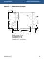
1
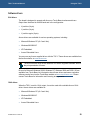
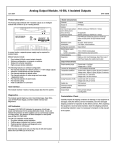
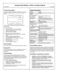
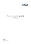
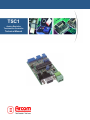
TSC1
Analog Resistive
Touchscreen Controller
Technical Manual
TSC1 Technical Manual
Definitions
Arcom is the trading name for Arcom Control Systems Inc and Arcom Control Systems Ltd.
Disclaimer
The information in this manual has been carefully checked and is believed to be accurate. Arcom assumes no responsibility
for any infringements of patents or other rights of third parties, which may result from its use.
Arcom assumes no responsibility for any inaccuracies that may be contained in this document. Arcom makes no commitment
to update or keep current the information contained in this manual.
Arcom reserves the right to make improvements to this document and/or product at any time and without notice.
Warranty
This product is supplied with a full 3 year warranty. Product warranty covers failure caused by any manufacturing defects.
Arcom will make all reasonable effort to repair the product or replace it with an identical variant. Arcom reserves the right to
replace the returned product with an alternative variant or an equivalent fit, form and functional product. Delivery charges will
apply to all returned products. Please go to www.arcom.com/support for information about product return forms.
Trademarks
Windows 98, Windows NT, Windows 2000 and Windows XP are trademarks or registered trademarks of the Microsoft
Corporation.
DuboxTM is a trademark of Framatome Connectors International.
3MTM and DynaproTM are trademarks of 3M Limited.
All other trademarks recognized.
Revision history
Manual
PCB
Date
Comments
Issue A
V1I1
8th Nov 2001
First release of manual.
Issue B
Issue C
Issue D
Issue E
V1I2
V1I2 mod A
V1I2 mod A
V1I2 mod C
th
Connector pinouts changed on V1 Iss2 boards.
th
10-bit Operation option added
rd
Jumper setting correction for 5-wire interface
11 July 2002
24 June 2003
23 July 2003
th
9 May 2005
© 2006 Arcom.
Arcom is a subsidiary of Eurotech Group.
www.eurotech.com
For contact details, see page 28.
Arcom operates a company-wide
quality management system
which has been certified by the
British Standards Institution (BSI)
as compliant with ISO9001:2000
Jumper LK4 operation added
TSC1 Technical Manual
Contents
Contents
Introduction ........................................................................................................................................4
Handling your board safely ....................................................................................................4
TSC1 touchscreen controller ‘at a glance’ .............................................................................5
Features of the TSC1.............................................................................................................6
About this manual ..............................................................................................................................7
Conventions ...........................................................................................................................7
Jumpers and connectors....................................................................................................................8
Jumpers .................................................................................................................................9
Connectors...........................................................................................................................16
PL3 - Serial port ...................................................................................................................16
PL1 - Alternative serial port..................................................................................................17
PL5 - Power input ................................................................................................................17
PL2 - 8-wire touchscreen interface ......................................................................................18
PL4 - 5-wire touchscreen interface ......................................................................................18
PL6 - 4-wire touchscreen interface ......................................................................................19
Using the TSC1................................................................................................................................20
Serial interface port..............................................................................................................20
Touchscreen interface..........................................................................................................20
Modes of operation ..............................................................................................................21
LEDs ....................................................................................................................................22
Software drivers ...................................................................................................................23
Temperature issues..............................................................................................................25
Interference due to RF emissions ........................................................................................26
Power supply ...................................................................................................................................27
Power input ..........................................................................................................................27
Appendix A – Contacting Arcom.......................................................................................................28
Appendix B – Compatible touchscreens ..........................................................................................29
Appendix C – Dimensional information............................................................................................30
Appendix D – Reference information ...............................................................................................31
Appendix E – Acronyms and abbreviations .....................................................................................32
Index ................................................................................................................................................33
© 2005 Arcom Issue E
3
TSC1 Technical Manual
Introduction
Introduction
The TSC1 is an analog resistive touchscreen controller board. It serves as an interface
between 4, 5 or 8-wire resistive touchscreens and an Arcom single board computer via
one of its serial ports.
For information about ordering boards, please contact a member of the Arcom sales
team. See Appendix A – Contacting Arcom, page 28.
Handling your board safely
Anti-static handling
This board contains CMOS devices that could be damaged in the event of static
electricity being discharged through them. At all times, please observe anti-static
precautions when handling the board. Always unpack and install it in an anti-static
working area.
Packaging
Should a board need to be returned to Arcom, please ensure that it is adequately
packed, preferably in the original packing material.
Use an anti-static bag for the board and use a box (rather than a bag) to physically
protect the board.
An anti-static bag is not required if the board is being returned in the original
Development Kit box, which has an anti-static foam interior.
Damage caused in transit may invalidate a warranty claim.
Electromagnetic compatibility (EMC)
The TSC1 is classified as a component with regard to the European Community EMC
regulations. It is the user’s responsibility to ensure that systems using the board are
compliant with the appropriate EMC standards.
Arcom EMC tests of the TSC1 have shown that the RF emissions of the board are well
below standard international EMC limits and that it is unlikely to contribute significantly
to the RF emissions spectrum of any system in which it is used.
© 2005 Arcom Issue E
4
TSC1 Technical Manual
Introduction
TSC1 touchscreen controller ‘at a glance’
Serial port
Alternative serial port
LEDs
8-wire touchscreen
interface
5-wire touchscreen
interface
Power
© 2005 Arcom Issue E
IC4 microcontroller
4-wire touchscreen interface
5
TSC1 Technical Manual
Introduction
Features of the TSC1
The features included in the TSC1 are described below.
Interfaces
•
Link selectable interface to 4, 5 or 8-wire resistive touchscreens.
•
RS232 interface to single board computer (4800 or 19200 baud).
•
Optional RS485 interface variant for long distance communication. (Contact the
Arcom sales team for further details; see page 28).
•
10-bit A/D (selectable 8-bit or 10-bit output to single board computer).
Operation mode
•
Operates in continuous touch mode.
•
Power and valid-touch LEDs.
•
5V DC power input.
•
Power consumption typically 35mA @ 5V DC.
•
0°C to +60°C (32°F to 140°F) operating temperature range.
•
-20°C to +85°C (-4°F to 185°F) storage temperature range.
•
743,000 hours; calculated using generic figures from MIL-HDBK-217F at ground
benign.
LEDs
Power
Temperature
MTBF
© 2005 Arcom Issue E
6
TSC1 Technical Manual
About this manual
About this manual
This manual describes the operation and use of the TSC1. It is designed to be a
reference and user manual and includes information about all aspects of the board.
Conventions
Symbols
The following symbols are used in this guide:
Symbol
Explanation
Note - information that requires your attention.
Tip - a handy hint that may provide a useful
alternative or save time.
Caution – proceeding with a course of action may
damage your equipment or result in loss of data.
Jumper is fitted.
Jumper is not fitted.
© 2005 Arcom Issue E
7
TSC1 Technical Manual
Jumpers and connectors
Jumpers and connectors
The following diagram shows the jumpers and connectors on the TSC1. Click on any
jumper or connector name for more information.
PL3
PL1
LK1
LK2
LK3
PL2
PL4
PL6
PL5
© 2005 Arcom Issue E
LK6
LK5 LK4 LK7 LK11 LK10 LK9 LK8
8
TSC1 Technical Manual
Jumpers and connectors
Jumpers
There are 11 user-selectable jumpers on the TSC1. They are summarised in the
following table:
Jumper
Description
See…
LK1
Reserved. Do not fit.
Page 9.
LK2
10-bit output select.
Page 9.
LK3
Baud select.
Page 10.
LK4
8-wire panel option.
Page 10.
LK5
5-wire panel select.
Page 11.
LK6
Low voltage programming.
Page 11.
LK7
5-wire voltage reference input.
Page 11.
LK8
4-wire resistive touchscreen interface.
Page 12.
LK9
5-wire voltage reference input and 4-wire resistive
touchscreen interface.
Page 12.
LK10
4-wire resistive touchscreen interface.
Page 12.
LK11
4-wire resistive touchscreen interface.
Page 12.
Reserved jumper - LK1
This jumper is unused. Do not fit.
Default setting:
10-bit output select - LK2
This jumper can be used to enable 10-bit output from the TSC1.
The host SBC must use compatible 10-bit driver software.
LK2
Description
Enable 10-bit output from TSC1.
Default setting:
TSC1 output is 8-bit only.
© 2005 Arcom Issue E
9
TSC1 Technical Manual
Jumpers and connectors
Baud select - LK3
This jumper can be used to change the baud rate from 4800 to 19200.
You should normally use 19200 when running in 10-bit mode and 4800 baud
when running in 8-bit mode.
LK3
Description
19200 baud.
Default setting:
4800 baud.
8-wire panel option - LK4
Some large 8-wire panels may have valid touches at the extreme edges of the panel
that are not detected as valid touches by the TSC1. You can fit this jumper to extend the
range of valid inputs for 4 and 8-wire operation.
This jumper is not fitted for normal operation.
LK4
Description
Range of valid inputs extended.
Default setting:
Standard input range.
© 2005 Arcom Issue E
10
TSC1 Technical Manual
Jumpers and connectors
5-wire panel select - LK5
This jumper must be fitted when interfacing to 5-wire resistive touchscreens. See also
jumpers LK7 and LK9, below.
LK5
Description
When interfacing with 5-wire resistive
touchscreens.
Default setting:
When interfacing with 4 or 8-wire
resistive touchscreens.
Low voltage programming - LK6
This jumper is for factory use only and is fitted when your TSC1 is supplied. Do not
remove.
Default setting:
5-wire voltage reference inputs - LK7, LK9
Fit these jumpers when interfacing to 5-wire resistive touchscreens. These jumpers are
also fitted when interfacing to 4-wire touchscreens (see 4-wire interface jumper settings,
below).
LK7
Description
When interfacing with 5-wire (and 4wire) resistive touchscreens.
Default setting:
When interfacing with 8-wire resistive
touchscreens.
LK9
Description
When interfacing with 5-wire (and 4wire) resistive touchscreens.
Default setting:
When interfacing with 8-wire resistive
touchscreens.
© 2005 Arcom Issue E
11
TSC1 Technical Manual
Jumpers and connectors
4-wire interface - LK8, LK9, LK10 and LK11
These jumpers are used when interfacing with 4- and 8-wire resistive touchscreens.
They must be fitted when interfacing to 4-wire resistive touchscreens, and removed
when using 8-wire touchscreens.
LK8
Description
Interface with 4-wire resistive
touchscreen.
Default setting:
Interface with 8-wire resistive
touchscreen.
LK9
Description
Interface with 4-wire resistive
touchscreen.
Default setting:
Interface with 8-wire resistive
touchscreen.
LK10
Description
Interface with 4-wire resistive
touchscreen.
Default setting:
Interface with 8-wire resistive
touchscreen.
LK11
Description
Interface with 4-wire resistive
touchscreen.
Default setting:
Interface with 8-wire resistive
touchscreen.
© 2005 Arcom Issue E
12
TSC1 Technical Manual
Jumpers and connectors
Jumper settings
The following diagrams illustrate the TSC1 jumper settings required for the interfaces
and output modes you might use.
4-wire interface, 8-bit output mode (factory default)
PWR TX
PL1
D1
D2
RX
D3
LK3
LK1 LK2
PL2
PL3
PL5
IC4
LK4
LK5
LK6
PL4
LK7
LK8
LK9
LK10
GND
+5V
PL6
LK11
4-wire interface, 10-bit output mode
PWR TX
PL1
D1
D2
RX
LK3
D3
LK1 LK2
PL2
PL3
PL5
LK4
LK5
LK6
IC4
PL4
LK7
LK8
LK9
LK10
GND
+5V
PL6
LK11
© 2005 Arcom Issue E
13
TSC1 Technical Manual
Jumpers and connectors
8-wire interface, 8-bit output mode
PWR TX
PL1
D1
D2
RX
LK3
D3
LK1 LK2
PL2
PL3
PL5
IC4
LK4
LK5
LK6
PL4
LK7
LK8
LK9
LK10
GND
+5V
PL6
LK11
8-wire interface, 10-bit output mode
PWR TX
PL1
D1
D2
RX
LK3
D3
LK1 LK2
PL2
PL3
PL5
LK4
LK5
LK6
IC4
PL4
LK7
LK8
LK9
LK10
GND
+5V
PL6
LK11
© 2005 Arcom Issue E
14
TSC1 Technical Manual
Jumpers and connectors
5-wire interface, 8-bit output mode
PWR TX
PL1
D1
D2
RX
LK3
D3
LK1 LK2
PL2
PL3
PL5
IC4
LK4
LK5
LK6
PL4
LK7
LK8
LK9
LK10
GND
+5V
PL6
LK11
5-wire interface, 10-bit output mode
PWR TX
PL1
D1
D2
RX
LK3
D3
LK1 LK2
PL2
PL3
PL5
LK4
LK5
LK6
IC4
PL4
LK7
LK8
LK9
LK10
GND
+5V
PL6
LK11
© 2005 Arcom Issue E
15
TSC1 Technical Manual
Jumpers and connectors
Connectors
There are 6 connectors on the TSC1.
Connector
Function
See …
PL3
Serial port.
Page 16.
PL1
Alternative serial port.
Page 17.
PL5
Power input.
Page 17.
PL2
8-wire touchscreen interface.
Page 18.
PL4
5-wire touchscreen interface.
Page 18.
PL6
4-wire touchscreen interface.
Page 19.
PL3 - Serial port
9-way D-type female connector.
Pin
Signal
Pin
Signal
1
Not connected
6
Not connected
2
TX to SBC
7
Not connected
3
RX (unused)
8
Reserved
4
Not connected
9
Reserved
5
GND (0V)
© 2005 Arcom Issue E
16
TSC1 Technical Manual
Jumpers and connectors
PL1 - Alternative serial port
10-way 0.1" IDC boxed header.
Pin
Signal
Pin
Signal
1
Not connected
2
Not connected
3
TX to SBC
4
Not connected
5
RX (unused)
6
Reserved
7
Not connected
8
Reserved
9
GND (0V)
10
Not connected
PL5 - Power input
3-way 2-part Phoenix connector.
The TSC1 is supplied with the mating 3-way connector.
Pin
Signal
1
+5V DC
2
GND
3
GND
© 2005 Arcom Issue E
3
1
17
TSC1 Technical Manual
Jumpers and connectors
PL2 - 8-wire touchscreen interface
8-way right-angled 0.1" Dubox type.
Suitable mating part: Dubox (FCI) housing 65240-008, crimps 76357-401.
Pin
Signal name
1
Te (Top Excite)
2
Ts (Top Sense)
3
Bs (Bottom Sense)
4
Be (Bottom Excite)
5
Le (Left Excite)
6
Ls (Left Sense)
7
Rs (Right Sense)
8
Re (Right Excite)
8
1
PL4 - 5-wire touchscreen interface
5-way right-angled 0.1" Dubox type.
Suitable mating part: Dubox (FCI) housing 65240-005, crimps 76357-401.
Pin
Signal name
1
H (Top Right)
2
X (Bottom Right)
3
S (Sense)
4
Y (Top Left)
5
L (Bottom Left)
© 2005 Arcom Issue E
5
1
18
TSC1 Technical Manual
Jumpers and connectors
PL6 - 4-wire touchscreen interface
4-way right-angled 0.1" Dubox type.
Suitable mating part: Dubox (FCI) housing 65240-004, crimps 76357-401.
Pin
Signal name
1
Y+ (Top)
2
Y- (Bottom)
3
X+ (Right)
4
X- (Left)
© 2005 Arcom Issue E
19
TSC1 Technical Manual
Using the TSC1
Using the TSC1
Serial interface port
The TSC1 serial port is a standard RS232 serial interface. PL3 should be connected to
a standard PC RS232 serial communications port, either directly, or via a serial port
extender cable (i.e. a straight through connection of pins 2, 3 and 5).
Do not use a null-modem crossover cable. The RS232 interface cable must not
be longer than 3m.
Only the transmit (TX) and receive (RX) signal lines (and ground) are used. Neither the
RS232 modem (hardware) handshaking signals nor software handshaking (Xon/Xoff)
are used.
As an alternative to PL3, the 10-way header connector (PL1) can be used instead. The
pin-out for this has been designed for connection via a straight pin-to-pin 10-way ribbon
cable to a 10-way header serial port connector used on many Arcom single board
computers.
Touchscreen interface
The TSC1 is connected to your resistive touchscreen via one of the Dubox style
connectors - PL2, PL4 or PL6.
Touchscreen type
Use connector
See…
4-wire
PL6
Page 19.
5-wire
PL4
Page 18.
8-wire
PL2
Page 18.
The pin-out and style of these connectors has been chosen to connect directly to many
of the more common touchscreen panels. However, you should check the pin-out of the
touchscreen you are using with the pin-out of the TSC1 connector (see Connectors,
page 16). An interface cable may be required to correctly connect the TSC1 with your
touchscreen.
© 2005 Arcom Issue E
20
TSC1 Technical Manual
Using the TSC1
A resistive touchscreen controller works by driving a potential difference across two
sides of the touch panel and then measuring the resulting voltage on another of the
panel wires when a touch is made. The TSC1 has been successfully tested with
unshielded ribbon cables up to 1.5m long between the TSC1 and the touchscreen. We
recommend, however, that any interface cable is kept as short as possible. This is
particularly important in areas of high RF emissions, which may induce noise onto the
touchscreen interface cable, resulting in an unstable or inaccurately reported touch
position.
Modes of operation
Touch mode
The TSC1 board currently only supports continuous touch mode. Whenever a valid
touch is detected on the touchscreen, the coordinates are passed to the processor
board. If the touch is continuous, the TSC1 continually transmits a stream of touch
coordinate data to the processor board until no touch is detected.
Output mode (8-bit or 10-bit)
The TSC1 uses a 10-bit A/D converter. It can, however, output with either 8-bit
resolution or 10-bit resolution.
8-bit output mode is used when using the TSC1 with a single board computer (or PC)
running with legacy or third party 8-bit driver software (and communicating at 4800
baud). Earlier TSC1 boards (V1I1 boards, or V1I2 boards without MOD status box ‘A’
marked) only ran in 8-bit mode. There are also a number of third party drivers available
that are compatible with the TSC1 running in 8-bit mode (see Software drivers on page
23).
10-bit output is the preferred mode of operation. The performance of the TSC1 is
greatly improved when running in 10-bit mode. Links LK2 and LK3 should be set to
select 10-bit output at 19200 baud. See Jumpers on page 9 for more information. The
Arcom 10-bit drivers must be used when running in this mode.
The TSC1 determines whether it should run in 8-bit or 10-bit mode only upon a
hardware reset. If changing link LK2 or LK3 the board must be reset to ensure
correct operation.
© 2005 Arcom Issue E
21
TSC1 Technical Manual
Using the TSC1
LEDs
The position of the LEDs on the TSC1 is shown in the following picture:
Power LED
TX (valid touch) LED
Each LED is described in more detail below.
Power LED
The PWR LED, D1, demonstrates that the board is correctly powered and that the
on-board microcontroller program is running.
Transmit active
The TX LED, D2, illuminates whenever there is a valid touch on the touchscreen panel.
Receive active
The RX LED, D3, is currently unused and reserved for future development.
© 2005 Arcom Issue E
22
TSC1 Technical Manual
Using the TSC1
Software drivers
8-bit drivers
The board is designed to operate with Arcom or Touch-Base touchscreen drivers.
Output from the board is at 4800 baud and in the configuration:
•
X position (1byte).
•
Y position (1byte).
•
Y position again (1byte).
Arcom drivers are available for various operating systems, including:
•
Microsoft Windows CE (v3.0 and .Net).
•
Windows 98/2000/XP.
•
XP Embedded.
•
Arcom Embedded Linux.
You may use any Arcom supplied driver with the TSC1. These drivers are available from
the Arcom website, at www.arcom.com.
The Arcom drivers must not be used with non-Arcom supplied hardware without
the prior permission of Arcom.
Drivers for Microsoft Windows 95/98, Windows NT, Windows 2000 and DOS 6.22 are
available from Touch-Base Ltd. Information about these drivers and some evaluation
software can be found on the Touch-Base website, at www.touch-base.com. Please
contact Touch-Base for information and licensing arrangements.
10-bit drivers
When the TSC1 is set for 10-bit output, it must be used with a suitable Arcom 10-bit
driver. Arcom drivers are available for:
•
Microsoft Windows CE (v3.0 and .Net).
•
Windows 98/2000/XP.
•
XP Embedded.
•
Arcom Embedded Linux.
© 2005 Arcom Issue E
23
TSC1 Technical Manual
Using the TSC1
These drivers are available from the Arcom website, at www.arcom.com. They expect
output from the TSC1 at 19200 baud.
Output from the board is in the configuration:
•
X coordinate LSB (least significant byte).
•
X coordinate MSB (most significant byte).
•
Y coordinate LSB.
•
Y coordinate MSB.
•
Y coordinate LSB.
•
Y coordinate MSB.
General software driver information
Once the software driver has been installed on your processor board or PC, the
touchscreen/touchscreen controller must be calibrated.
Instructions for installing the drivers and for calibrating the touchscreen are included
with the Arcom supplied drivers.
The calibration data is stored on the PC (or single board computer) that is
running the software driver. If the touchscreen or touchscreen controller used is
changed, the calibration procedure must be repeated.
For an explanation of calibration issues with respect to temperature, see Operation over
a wide temperature range, on the following page.
There may be a small difference in the reported position of a touch for a short
period after the TSC1 is switched on, while the TSC1 microcontroller reaches its
operating temperature.
© 2005 Arcom Issue E
24
TSC1 Technical Manual
Using the TSC1
Temperature issues
The TSC1 has been designed and tested to operate over a temperature range of 0°C to
60°C (32°F to 140°F). This is a wider range than the effective operating range of most
resistive touchscreen panels.
The storage temperature range of the TSC1 is -20°C to +85°C (-4°F to 185°F).
Operation below 0°C
Tests conducted at Arcom have found that many analog resistive touchscreen
membranes become distorted when exposed to temperatures below 0°C (32°F). The
TSC1 controller is not designed to operate below 0°C (32°F).
Operation over a wide temperature range
When used over a wide temperature range, the measured touch position on a
touchscreen panel will vary relative to the temperature of both the touchscreen and the
TSC1. The absolute difference between the actual touch position and measured touch
position will be most prominent in the top right hand corner of the panel for most
touchscreen panels (where the X and Y coordinates are largest).
To minimise the positional error associated with temperature change, the touchscreen
calibration procedure should ideally be carried out at a temperature in the middle of the
temperature range that it is to be used over.
If a touchscreen is expected to be used normally near one extreme of the
temperature range, then it makes sense to calibrate when it is at this
temperature.
The exact positional error over the full temperature range depends on the touchscreen
used. Tests at Arcom have shown that the error due to the temperature of the
touchscreen is normally greater than that due to the temperature of the TSC1.
© 2005 Arcom Issue E
25
TSC1 Technical Manual
Using the TSC1
Interference due to RF emissions
The TSC1 resistive touchscreen controller works by driving a potential difference across
two sides of the touch panel and then measuring the resulting voltage on another of the
panel wires when a touch is made. If used in an area where there are high RF
emissions, noise may be induced onto the touchscreen interface cable, resulting in an
inaccurate response or even a complete failure of operation.
The backlight inverters used with TFT flat panel displays can be a source of RF
interference. It is recommended that the backlight inverter and its cabling be kept as far
as possible from the TSC1 and its cabling. The inverter cabling and the TSC1
touchscreen interface cable should not be routed together.
© 2005 Arcom Issue E
26
TSC1 Technical Manual
Power supply
Power supply
Power input
The TSC1 should be powered from a regulated +5V DC supply (+/- 0.25V). Current
consumption of the board is typically 35mA. The polarity of the power input connector is
shown on the PCB.
Powering the board with the incorrect polarity or with a voltage greater than
5.25V may damage the board and will invalidate the warranty.
© 2005 Arcom Issue E
27
TSC1 Technical Manual
Appendix A – Contacting Arcom
Appendix A – Contacting Arcom
Arcom sales
Arcom’s sales team is always available to assist you in choosing the board that best
meets your requirements. Contact your local sales office or hotline.
Sales office US
Sales office Europe
Arcom
7500W 161st Street
Overland Park
Kansas
66085
USA
Arcom
Clifton Road
Cambridge
CB1 7EA
UK
Tel:
Fax:
E-mail:
913 549 1000
913 549 1002
[email protected]
Tel:
Fax:
E-mail:
01223 411 200
01223 410 457
[email protected]
Full information about all Arcom products is available on our Web site at www.arcom.com.
While Arcom’s sales team can assist you in making your decision, the final
choice of boards or systems is solely and wholly the responsibility of the buyer.
Arcom’s entire liability in respect of the boards or systems is as set out in
Arcom’s standard terms and conditions of sale. If you intend to write your own
low level software, you can start with the source code on the disk supplied. This
is example code only to illustrate use on Arcom’s products. It has not been
commercially tested. No warranty is made in respect of this code and Arcom
shall incur no liability whatsoever or howsoever arising from any use made of
the code.
Technical support
Arcom has a team of technical support engineers who can provide assistance if you
have any problems with your TSC1 board.
Technical support US
Technical support Europe
Tel:913 549 1010
Tel:+44 (0)1223 412 428
Fax:913 549 1001
Fax:+44 (0)1223 403 409
E-mail:[email protected]
E-mail:[email protected]
© 2005 Arcom Issue E
28
TSC1 Technical Manual
Appendix B – Compatible touchscreens
Appendix B – Compatible touchscreens
The following table provides a list of some of the resistive touchscreen panels that have
been tested with the TSC1:
Manufacturer
Model number
Number of
wires
Panel
size
Contact URL
3M Dynapro
DTFP# 95638
4
6.4"
3M Touch Systems
DTFP# 95627
4
10.4"
RES-15.1-PL8
8
15.1"
AMT Corp.
9501
4
6.4"
AMT
ELO
487669-000 (also called
FLT06.4-001-0H0)
5
6.4"
Elo TouchSystems
WASP
WSP9724
4
12.1"
WASP touchscreens
If you are using a touchscreen panel not on this list and you have difficulty controlling it
using the TSC1, please contact the Arcom Technical Support team. See Appendix A –
Contacting Arcom, page 28. Please have available the full details of the touchscreen
panel, including manufacturer and model number, panel size, number of wires (i.e. 4, 5
or 8), and the panel connector pin-out. Also, please provide details of the TSC1 link
settings, the version, issue and mod status of the TSC1, and the version and issue of
the TSC1 firmware (printed on the label of IC4 - see TSC1 touchscreen controller ‘at a
glance’, page 5).
© 2005 Arcom Issue E
29
TSC1 Technical Manual
Appendix C – Dimensional information
Appendix C – Dimensional information
7.3
PL2
'A'
PL1
'A'
38.7
50.0
PL3
PL4
22.9
PL5
PL6
15.9
51.4
59.1
4.4
8.4
'A'
75.0
BOARD OUTLINE 75.0 X 50.0
ALL DIMENSIONS IN MM
TOLERANCES +/- 0.1 mm
'A' HOLES 3 OFF - 3.25 (128 THOU)
© 2005 Arcom Issue E
30
TSC1 Technical Manual
Appendix D – Reference information
Appendix D – Reference information
Product information
Product notices, updated drivers, support material, 24 hour online ordering:
www.arcom.com
Touch-Base driver information
Information about drivers for Microsoft Windows 95/98, Windows NT, Windows 2000
and DOS 6.22 and some evaluation software.
www.touch-base.com
3M Touch Systems panel
Information about the touchscreen panel manufactured by 3M Touch Systems:
www.3m.com/us/electronics_mfg/touch_systems/index.jhtml
AMT Corp touchscreen panel
Information about the touchscreen panel manufactured by AMT Corp:
www.amtouch.com.tw
Elo TouchSystems panel
Information about the touchscreen panel manufactured by Elo TouchSystems:
www.elotouch.com
WASP touchscreens panel
Information about the touchscreen panel manufactured by WASP touchscreens:
www.waspswitches.co.uk
© 2005 Arcom Issue E
31
TSC1 Technical Manual
Appendix E – Acronyms and abbreviations
Appendix E – Acronyms and abbreviations
A/D
CMOS
DC
EMC
FCI
IDC
LED
MTBF
PC
PCB
RF
RS
RX
TFT
TSC
TX
© 2005 Arcom Issue E
Analog to Digital
Complementary Metal Oxide Semiconductor
Direct Current
Electromagnetic Compatibility
Framatome Connectors International
Internet Database Connector
Light Emitting Diode
Mean Time Between Failures
Personal Computer
Printed Circuit Board
Radio Frequency
Recommended Standard
Receive
Thin Film Transistor
TouchScreen Controller
Transmit
32
TSC1 Technical Manual
Index
Index
1
C
10-bit
drivers · 23
output · 9
output mode · 21
cable · 20, 21
inverter · 26
routing · 26
touchscreen interface · 26
calibration · 24, 25
CMOS · 4
code, source · 28
compatible touchscreens · 29
connectors · 16
Phoenix · 17
contact details · 28
continuous touch mode · 21
copyright · 2
3
3M · 29, 31
4
4-wire touchscreen · 12, 19, 20
5
5-wire
panel · 11
touchscreen · 18, 20
8
8-bit output mode · 21
8-wire
panel · 10
touchscreen · 12, 18, 20
A
abbreviations · 32
acronyms · 32
AMT · 29, 31
anti-static · 4
B
backlight inverters · 26
baud select · 10
D
dimensional information · 30
disclaimer · 2
drivers · 23
10-bit · 23
Touch-Base · 31
touchscreen calibration · 24
Dubox · 18, 19
E
ELO · 29, 31
EMC · 4
F
features · 6
H
handshaking · 20
I
interfaces · 6
inverter cable · 26
© 2005 Arcom Issue E
33
TSC1 Technical Manual
J
jumpers · 9
reserved · 9
settings · 13
L
LED · 6
power · 22
receive · 22
transmit · 22
LK1 · 9
LK10 · 12
LK11 · 12
LK2 · 9
LK3 · 10
LK4 · 10
LK5 · 11
LK6 · 11
LK7 · 11
LK8 · 12
LK9 · 11, 12
Index
PL6 · 19, 20
polarity · 27
port
serial · 16, 20
serial, alternative · 17
power
consumption · 6, 27
input · 6
input connector · 27
LED · 22
supply · 27
product information · 31
R
receive LED · 22
returns · 4
RF emissions · 4, 21, 26
RS232 · 6, 20
RS485 · 6
RX · 22
S
N
serial port · 16, 17, 20
signal lines · 20
source code · 28
static · 4
storage temperature · 6, 25
sub-zero temperatures · 25
support, technical · 28
symbols · 7
noise reduction · 21, 26
null-modem · 20
T
M
mode · 6
output · 21
touch · 21
MTBF · 6
O
operating
systems · 23
temperature · 6, 25
operation mode · 6
output
mode · 21
select · 9
P
packaging · 4
Phoenix connector · 17
PL1 · 20
PL2 · 18, 20
PL3 · 16, 20
PL4 · 18, 20
PL5 · 17
© 2005 Arcom Issue E
technical support · 28
temperature
operating · 6, 25
range · 25
storage · 6, 25
sub-zero · 25
touch mode · 21
Touch-Base · 23
drivers · 31
touchscreens, compatible · 29
trade marks · 2
transmit LED · 22
TX · 22
W
warranty · 2, 4
WASP · 29, 31
Windows XP · 23
34