1
16950ua.bk Page 1 Thursday, April 29, 1999 1:28 PM
®
SuperStack® II Switch 1100
User Guide
3C16950, 3C16951
http://www.3com.com/
Part No. DUA1695-0AAA04
Published April 1999
16950ua.bk Page 2 Thursday, April 29, 1999 1:28 PM
3Com Corporation
5400 Bayfront Plaza
Santa Clara, California
95052-8145
Copyright © 1999, 3Com Technologies. All rights reserved. No part of this documentation may be reproduced
in any form or by any means or used to make any derivative work (such as translation, transformation, or
adaptation) without written permission from 3Com Technologies.
3Com Technologies reserves the right to revise this documentation and to make changes in content from time
to time without obligation on the part of 3Com Technologies to provide notification of such revision or
change.
3Com Technologies provides this documentation without warranty, term, or condition of any kind, either
implied or expressed, including, but not limited to, the implied warranties, terms or conditions of
merchantability, satisfactory quality, and fitness for a particular purpose. 3Com may make improvements or
changes in the product(s) and/or the program(s) described in this documentation at any time.
If there is any software on removable media described in this documentation, it is furnished under a license
agreement included with the product as a separate document, in the hard copy documentation, or on the
removable media in a directory file named LICENSE.TXT or !LICENSE.TXT. If you are unable to locate a copy,
please contact 3Com and a copy will be provided to you.
UNITED STATES GOVERNMENT LEGEND
If you are a United States government agency, then this documentation and the software described herein are
provided to you subject to the following:
All technical data and computer software are commercial in nature and developed solely at private expense.
Software is delivered as “Commercial Computer Software” as defined in DFARS 252.227-7014 (June 1995) or
as a “commercial item” as defined in FAR 2.101(a) and as such is provided with only such rights as are
provided in 3Com’s standard commercial license for the Software. Technical data is provided with limited rights
only as provided in DFAR 252.227-7015 (Nov 1995) or FAR 52.227-14 (June 1987), whichever is applicable.
You agree not to remove or deface any portion of any legend provided on any licensed program or
documentation contained in, or delivered to you in conjunction with, this User Guide.
Unless otherwise indicated, 3Com registered trademarks are registered in the United States and may or may not
be registered in other countries.
3Com, the 3Com logo, Net Age, SmartAgent, SuperStack and Transcend are registered trademarks of
3Com Corporation. CoreBuilder and PACE are trademarks of 3Com Corporation. 3ComFacts is a service mark
of 3Com Corporation.
All other company and product names may be trademarks of the respective companies with which they are
associated.
Environmental Statement
It is a 3Com policy to be environmentally friendly in all operations. This manual is printed on paper that comes
from sustainable, managed European forests. The production process for making the pulp has a reduced AOX
level (adsorbable organic halogen) resulting in elemental chlorine-free paper.
The paper is fully biodegradable and recyclable.
16950ua.bk Page iii Thursday, April 29, 1999 1:28 PM
CONTENTS
ABOUT THIS GUIDE
Conventions 8
Related Documentation 9
Year 2000 Compliance 10
Documentation Comments 10
1
INTRODUCING
THE
SWITCH 1100
About the SuperStack II Switch 1100 12
Summary of Features 12
Switch 1100 — Front View Detail 13
Port Connections 13
LEDs 14
Switch 1100 — Rear View Detail 15
Unit Information Label 15
Power Socket 15
Redundant Power System Socket 15
Console Port 15
Expansion Module Slot 16
Transceiver Module Slot 16
Matrix Port 16
Network Configuration Examples 17
Network Segmentation I 17
Network Segmentation II 18
Desktop Switching 19
Configuration Rules for Fast Ethernet 20
Configuration Rules with Full Duplex 21
2
INSTALLING
THE
SWITCH
Choosing a Suitable Site
Rack-mounting 24
24
16950ua.bk Page iv Thursday, April 29, 1999 1:28 PM
Placing Units On Top of Each Other 25
Stacking Units 26
Stacking Two Units 26
Stacking Up To Four Units 27
The Power-up Sequence 29
Connecting a Redundant Power System
Powering-up the Switch 1100 29
Checking for Correct Operation 29
Choosing the Correct Cables 30
Solving Problems Indicated by LEDs 31
Managing the Switch 32
A
SAFETY INFORMATION
Important Safety Information 34
L’information de Sécurité Importante 36
Wichtige Sicherheitsinformationen 38
B
PIN-OUTS
Null Modem Cable 39
PC-AT Serial Cable 39
Modem Cable 40
RJ45 Pin Assignments 40
C
TECHNICAL SPECIFICATIONS
D
TECHNICAL SUPPORT
Online Technical Services 43
World Wide Web Site 43
3Com Knowledgebase Web Services 43
3Com FTP Site 44
3Com Bulletin Board Service 44
3Com Facts Automated Fax Service 45
Support from Your Network Supplier 45
Support from 3Com 45
Returning Products for Repair 47
iv
29
16950ua.bk Page v Thursday, April 29, 1999 1:28 PM
GLOSSARY
INDEX
3COM CORPORATION LIMITED WARRANTY
EMC STATEMENTS
v
16950ua.bk Page vi Thursday, April 29, 1999 1:28 PM
vi
16950ua.bk Page 7 Thursday, April 29, 1999 1:28 PM
ABOUT THIS GUIDE
This guide provides all the information you need to install and use a
SuperStack ® II Switch 1100 unit with default settings. If you want to
change the way the Switch works using management software, refer to
the “SuperStack II Switch Management Guide” (part number
DUA1695-0BAA0x).
The guide is intended for use by network administrators who are
responsible for installing and setting up network equipment;
consequently, it assumes a basic working knowledge of LANs (Local Area
Networks).
This guide is intended for use with both Switch 1100 models:
■
3C16950 — 24 10BASE-T ports
■
3C16951 — 12 10BASE-T ports
All pictures and example screens show the 24-port model, however, all
procedures apply to the 24-port model and the 12-port model.
If the information in the release notes that are shipped with your product
differs from the information in this guide, follow the instructions in the
release notes.
Most user guides and release notes are available in Adobe Acrobat
Reader Portable Document Format (PDF) or HTML on the 3Com
World Wide Web site:
http://www.3com.com/
16950ua.bk Page 8 Thursday, April 29, 1999 1:28 PM
8
ABOUT THIS GUIDE
Conventions
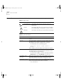
Table 1 and Table 2 list conventions that are used throughout this guide.
Table 1 Notice Icons
Icon
Notice Type
Description
Information note
Information that describes important features or
instructions
Caution
Information that alerts you to potential loss of data or
potential damage to an application, system, or device
Warning
Information that alerts you to potential personal injury
Table 2 Text Conventions
Convention
Description
Screen displays This typeface represents information as it appears on the
screen.
Syntax
The word “syntax” means that you must evaluate the syntax
provided and then supply the appropriate values for the
placeholders that appear in angle brackets. Example:
To enable RIPIP, use the following syntax:
SETDefault !<port> -RIPIP CONTrol =
Listen
In this example, you must supply a port number for <port>.
Commands
The word “command” means that you must enter the
command exactly as shown and then press Return or Enter.
Commands appear in bold. Example:
To remove the IP address, enter the following command:
SETDefault !0 -IP NETaddr = 0.0.0.0
The words “enter”
and “type”
When you see the word “enter” in this guide, you must type
something, and then press Return or Enter. Do not press
Return or Enter when an instruction simply says “type.”
Keyboard key names
If you must press two or more keys simultaneously, the key
names are linked with a plus sign (+). Example:
Press Ctrl+Alt+Del
16950ua.bk Page 9 Thursday, April 29, 1999 1:28 PM
Related Documentation
9
Table 2 Text Conventions (continued)
Convention
Description
Words in italics
Italics are used to:
■
■
■
Emphasize a point.
Denote a new term at the place where it is defined in the
text.
Identify menu names, menu commands, and software
button names. Examples:
From the Help menu, select Contents.
Click OK.
Related
Documentation
In addition to this guide, each Switch 1100 document set includes the
following:
■
Management Guide (Part Number DUA1695-0BAA0x)
This guide contains all the management information for the Switch.
■
Quick Reference Guide (Part Number DQA1695-0AAA0x)
This guide contains a quick summary of the hardware and software
information for the Switch
■
Quick Installation Guide (Part Number DIA1695-0AAA0x)
This guide contains a summary of the package contents, and a quick
summary of the installation information for the Switch.
■
Release Notes (Part Number DNA1695-0AAA0x)
These notes provide information about the current software release,
including new features, modifications, and known problems.
■
SuperStack II Switch Help
This help provides information about the web interface software of
the Switch. It is supplied on the SuperStack II Switch CD-ROM.
■
SuperStack II Switch README File
This file provides information about the current software release,
including new features, modifications, and known problems.
16950ua.bk Page 10 Thursday, April 29, 1999 1:28 PM
10
ABOUT THIS GUIDE
In addition, there are other publications you may find useful:
Year 2000
Compliance
■
Documentation accompanying the Expansion Modules.
■
Documentation accompanying the Transceiver Modules.
■
Documentation accompanying the Advanced Redundant Power
System.
For information on Year 2000 compliance and 3Com products, visit the
3Com Year 2000 Web page:
http://www.3com.com/products/yr2000.html
Documentation
Comments
Your suggestions are very important to us. They will help make our
documentation more useful to you. Please e-mail comments about this
document to 3Com at:
[email protected]
Please include the following information when commenting:
■
Document title
■
Document part number (on the title page)
■
Page number (if appropriate)
Example:
■
SuperStack II Switch 1100 User Guide
■
Part Number DUA1695-0AAA03
■
Page 21
16950ua.bk Page 11 Thursday, April 29, 1999 1:28 PM
1
INTRODUCING THE SWITCH 1100
This chapter contains introductory information about the Switch and how
it can be used in your network. It covers the following topics:
■
About the SuperStack II Switch 1100
■
Switch 1100 — Front View Detail
■
Switch 1100 — Rear View Detail
■
Network Configuration Examples
■
Configuration Rules for Fast Ethernet
■
Configuration Rules with Full Duplex
16950ua.bk Page 12 Thursday, April 29, 1999 1:28 PM
12
CHAPTER 1: INTRODUCING THE SWITCH 1100
About the
SuperStack II
Switch 1100
The SuperStack® II system solves the problem of growth in dynamic
network environments and provides everything you need for successful
workgroup networking. Much more than a collection of stackable
components, the system comprises a complete, integrated architecture of
modular parts that are easy to install and use.
As part of this SuperStack II system, the Switch 1100 meets the challenge
of modern LANs and allows you to add features and capacity as your
network expands.
Summary of Features
The Switch has the following hardware features:
■
12 or 24 Ethernet 10BASE-T ports
■
Two Fast Ethernet auto-negotiating 10BASE-T/100BASE-TX ports
■
Matrix port for connecting units in the Switch 1100/3300 family to
form a stack:
■
■
Connect two units back-to-back using a single Matrix Cable
Connect up to four units using Matrix Cables linked to a Matrix
Module
■
Slot for an Expansion Module
■
Slot for a Transceiver Module (10Mbps Ethernet)
■
SuperStack II architecture:
■
■
Connects to Redundant Power System / Uninterruptible Power
System
19-inch rack or stand-alone mounting
For information about the software features of the Switch, refer to the
“SuperStack II Switch Management Guide” (DUA1695-0BAA0x).
16950ua.bk Page 13 Thursday, April 29, 1999 1:28 PM
Switch 1100 — Front View Detail
13
Switch 1100 —
Front View Detail
Figure 1 Switch 1100 — Front view
Port Connections
10BASE-T Ports
The Switch has 12 or 24 10BASE-T ports configured as MDIX (cross-over).
The maximum segment length is 100m (328ft) over Category 3, 4, or 5
twisted pair cable.
As these ports are configured as MDIX (cross-over), you need to use a
cross-over cable to connect to devices whose ports are MDIX-only. See
“Choosing the Correct Cables” on page 30 for more information.
10BASE-T/100BASE-TX Ports
The Switch has two auto-negotiating 10BASE-T/100BASE-TX ports
configured as MDIX (cross-over). These ports can be set to 10BASE-T half
duplex, 10BASE-T full duplex, 100BASE-TX half duplex, 100BASE-TX full
duplex, or they can automatically detect the speed and duplex mode of a
link and provide the appropriate connection. The maximum segment
length is 100m (328ft) over Category 5 twisted pair cable.
As these ports are configured as MDIX (cross-over), you need to use a
cross-over cable to connect to devices whose ports are MDIX-only. See
“Choosing the Correct Cables” on page 30 for more information.
16950ua.bk Page 14 Thursday, April 29, 1999 1:28 PM
14
CHAPTER 1: INTRODUCING THE SWITCH 1100
LEDs
Table 3 lists the LEDs visible on the front of the Switch, and their states
according to color. For information on using the LEDs for problem solving,
see “Checking for Correct Operation” on page 29.
Table 3 LED behavior
LED
Color
Indicates
TCVR
Yellow
Port 1 is a Transceiver Module fitted to the rear of the
Switch.
Off
Port 1 is operating as a 10BASE-T port.
Port Status LEDs
Packet
Status
Yellow
Packets are being transmitted/received on the port.
Off
No packets are being transmitted/received on the port.
Green
A link is present, and the port is enabled.
Green flashing
A link is present, but the port is disabled.
Off
No link is present.
Expansion Module Port Status LEDs
Packet
Yellow
Yellow
Packets are being transmitted/received on the
Expansion Module port(s).
No packets are being transmitted/received on the
Expansion Module port(s).
A valid Expansion Module is installed.
Yellow flashing
An unrecognized Expansion Module is installed.
Off
No Expansion Module is installed.
Green
The Switch forms a stack with other Switch units; the
LED indicates the position of the Switch in the stack
and that a link is present. Note that although there are
eight LEDs, only four Switch units can be stacked at
present.
Off
The Switch is stand-alone.
Off
Status
Unit LEDs
1–8
Power/Self Test LED
Green
The Switch is powered-up.
Green flashing
The Switch is either downloading software or is
initializing (which includes running a Power On Self
Test).
Yellow
The Switch has failed its Power On Self Test.
Off
The Switch is not receiving power.
16950ua.bk Page 15 Thursday, April 29, 1999 1:28 PM
Switch 1100 — Rear View Detail
15
Switch 1100 — Rear
View Detail
Figure 2 Switch 1100 — Rear view
Unit Information
Label
This label shows the following:
■
The 3Com product name of the Switch
■
The 3Com 3C number of the Switch
■
The unique MAC address (Ethernet address) of the Switch
■
The serial number of the Switch
You may need this information for fault reporting purposes.
Power Socket
The Switch automatically adjusts its power setting to any supply voltage
in the range 90–240V A.C.
Redundant Power
System Socket
To protect against internal power supply failure, you can use this socket
to connect a SuperStack II Advanced Redundant Power System (RPS) to
the Switch. See “Connecting a Redundant Power System” on page 29.
Console Port
The console port allows you to connect a terminal and perform remote or
local out-of-band management. The console port uses standard null
modem cable and is set to auto-baud, 8 data bits, no parity and 1 stop
bit.
16950ua.bk Page 16 Thursday, April 29, 1999 1:28 PM
16
CHAPTER 1: INTRODUCING THE SWITCH 1100
Expansion Module
Slot
You can use this slot to install an Expansion Module; for example, a
100BASE-FX Module that provides an additional high-speed link, or a
Matrix Module that provides four matrix ports for stacking Switch units
together. 3Com provides a range of Expansion Modules; contact your
supplier for availability. For more information about Matrix Modules, see
“Stacking Units” on page 26.
When an Expansion Module is not installed, ensure the blanking plate is
secured in place.
Transceiver Module
Slot
You can use this slot to install a Transceiver Module. When a Transceiver
Module is installed, the Transceiver Module port becomes port 1 and the
port labelled 1 on the front panel becomes inactive. The Transceiver
Module can provide a 10Mbps Ethernet half duplex link to the rest of
your network using various media such as fiber and coaxial cabling.
When a Transceiver Module is not installed, ensure the blanking plate is
secured in place.
Matrix Port
The matrix port allows you to:
■
Stack the Switch with another unit in the Switch 1100/3300 family
using a single Matrix Cable
■
Stack the Switch with up to three other units in the Switch 1100/3300
family, if one of the units has a Matrix Module installed
For more information about the role of the matrix port, see “Stacking
Units” on page 26.
16950ua.bk Page 17 Thursday, April 29, 1999 1:28 PM
Network Configuration Examples
Network
Configuration
Examples
Network
Segmentation I
17
The following illustrations show some examples of how the Switch can be
placed on your network.
Figure 3 shows how the Switch 1100 fits into a large corporate network
with a Fast Ethernet infrastructure. A Switch is positioned on each floor
and servers are centralized in the basement.
Figure 3 Using the Switch 1100 to segment your network
16950ua.bk Page 18 Thursday, April 29, 1999 1:28 PM
18
CHAPTER 1: INTRODUCING THE SWITCH 1100
Network
Segmentation II
Figure 4 shows the Switch 1100 in a second workgroup situation. This
setup could be that of a small office within a large corporation, or part of
a larger corporate network. Most of the switch ports have multiple
endstations.
Figure 4 Using the Switch 1100 to segment your network
16950ua.bk Page 19 Thursday, April 29, 1999 1:28 PM
Network Configuration Examples
Desktop Switching
19
Figure 5 shows the Switch 1100 used for a group of users in a large
corporate network. Here switching is brought to the desktop with a
single endstation per port. Local servers are connected via 100Mbps Fast
Ethernet links.
Figure 5 Using the Switch 1100 in a desktop environment
16950ua.bk Page 20 Thursday, April 29, 1999 1:28 PM
20
CHAPTER 1: INTRODUCING THE SWITCH 1100
Configuration Rules
for Fast Ethernet
The topology rules for 100Mbps Fast Ethernet are slightly different to
those for 10Mbps Ethernet. Figure 6 illustrates the key topology rules and
provides examples of how they allow for large-scale Fast Ethernet
networks.
Figure 6 Fast Ethernet configuration rules
16950ua.bk Page 21 Thursday, April 29, 1999 1:28 PM
Configuration Rules with Full Duplex
21
The key topology rules are:
Configuration Rules
with Full Duplex
■
Maximum UTP cable length is 100m (328ft) over Category 5 cable.
■
A 412m (1352ft) fiber run is allowed for connecting switch-to-switch,
or endstation-to-switch, using half-duplex 100BASE-FX.
■
A total network span of 325m (1066ft) is allowed in single-repeater
topologies (one hub stack per wiring closet with a fiber run to the
collapsed backbone); for example, a 225m (738ft) fiber link from a
repeater to a router or switch, plus a 100m (328ft) UTP link from a
repeater out to the endstations.
The Switch provides full duplex support for all its fixed ports, including
Expansion Module ports. Full duplex allows packets to be transmitted and
received simultaneously and, in effect, doubles the potential throughput
of a link.
With full duplex, the Ethernet topology rules are the same, but the Fast
Ethernet rules are:
■
Maximum UTP cable length is 100m (328ft) over Category 5 cable.
■
A 2km (6562ft) fiber link is allowed for connecting switch-to-switch,
or endstation-to-switch.
16950ua.bk Page 22 Thursday, April 29, 1999 1:28 PM
22
CHAPTER 1: INTRODUCING THE SWITCH 1100
16950ua.bk Page 23 Thursday, April 29, 1999 1:28 PM
2
INSTALLING THE SWITCH
This chapter contains the information you need to install and set up the
Switch. It covers the following topics:
■
Choosing a Suitable Site
■
Rack-mounting
■
Placing Units On Top of Each Other
■
Stacking Units
■
The Power-up Sequence
■
Choosing the Correct Cables
■
Solving Problems Indicated by LEDs
■
Managing the Switch
WARNING: Safety Information. Before installing or removing any
components from the Switch 1100 or carrying out any maintenance
procedures, you must read the safety information provided in Appendix A
of this guide.
AVERTISSEMENT: Consignes de sécurité. Avant d'installer ou d'enlever
tout composant du Switch 1100 ou d'entamer une procédure de
maintenance, lisez les informations relatives à la sécurité qui se trouvent
dans l'Appendice A de ce guide.
WARNHINWEIS: Sicherheitsinformationen. Bevor Sie Komponenten
aus dem Switch 1100 entfernen oder dem Switch 3300 hinzufuegen
oder Instandhaltungsarbeiten verrichten, lesen Sie die
Sicherheitsanweisungen, die in Appendix A (Anhang A) in diesem
Handbuch aufgefuehrt sind.
16950ua.bk Page 24 Thursday, April 29, 1999 1:28 PM
24
CHAPTER 2: INSTALLING THE SWITCH
Choosing a Suitable
Site
The Switch is suited for use in an office environment where it can be
mounted in a standard 19-inch equipment rack, or free standing.
Alternatively, the Switch can be rack-mounted in a wiring closet or
equipment room. A rack-mounting kit, containing two mounting
brackets and six screws, is supplied with the Switch.
When deciding where to position the Switch, ensure that:
■
You are able to meet the configuration rules detailed in
“Configuration Rules for Fast Ethernet” on page 20.
■
The Switch is accessible and cables can be connected easily.
■
Cabling is away from:
■
■
Rack-mounting
Sources of electrical noise such as radios, transmitters and
broadband amplifiers
Power lines and fluorescent lighting fixtures
■
Water or moisture cannot enter the case of the Switch.
■
Air-flow is not restricted around the Switch or through the vents in the
side of the Switch. We recommend that you provide a minimum of
25mm (1in.) clearance.
■
No more than four Switch units are placed on top of one another, if
the units are free standing.
The Switch is 1.5U high and fits in most standard 19-inch racks.
CAUTION: Disconnect all cables from the Switch before continuing.
Remove all self adhesive pads from the underside of the Switch if they
have been fitted.
1 Place the Switch the right way up on a hard flat surface, with the front
facing towards you.
2 Locate a mounting bracket over the mounting holes on one side of the
Switch, as shown in Figure 7.
16950ua.bk Page 25 Thursday, April 29, 1999 1:28 PM
Placing Units On Top of Each Other
25
Figure 7 Fitting a bracket for rack mounting
3 Insert the three screws and tighten with a suitable screwdriver.
You must use the screws supplied with the mounting brackets. Damage
caused to the unit by using incorrect screws invalidates your warranty.
4 Repeat steps 2 and 3 for the other side of the Switch.
5 Insert the Switch into the 19-inch rack and secure with suitable screws
(not provided). Ensure that ventilation holes are not obstructed.
6 Connect network cabling.
Placing Units On
Top of Each Other
If the Switch units are free-standing, up to four units can be placed one
on top of the other. If you are mixing a variety of SuperStack II Switch and
Hub units, the smaller units must be positioned at the top.
If you are placing Switch units one on top of the other, you must use the
self-adhesive rubber pads supplied. Apply the pads to the underside of
each Switch, sticking one in the marked area at each corner. Place the
Switch units on top of each other, ensuring that the pads of the upper
unit line up with the recesses of the lower unit.
16950ua.bk Page 26 Thursday, April 29, 1999 1:28 PM
26
CHAPTER 2: INSTALLING THE SWITCH
Stacking Units
Units in the Switch 1100/3300 family can be stacked together and then
treated as a single manageable unit with one IP address.
You can stack Switch units together in two ways:
Stacking Two Units
■
The matrix port on the rear of the Switch allows you to connect two
Switch units back-to-back. For this you need a Matrix Cable (part
number 3C16965). Contact your supplier for details.
■
The Expansion Module slot at the rear of the Switch allows you to
install a Matrix Module (part number 3C16960). The Matrix Module
provides four ports and allows you to interconnect up to four Switch
units using Matrix Cables.
You can stack two Switch units with a single Matrix Cable. To do this:
1 Power-off both units.
2 Arrange the units as required. They can be rack-mounted or
free-standing; if you choose to have them free-standing, remember to
position the rubber feet as detailed in “Placing Units On Top of Each
Other” on page 25. When positioning the units, note that Matrix Cables
are 1m (3.28ft) long.
3 As shown in Figure 8, connect one end of the Matrix Cable to the matrix
port of the top Switch, and the other end to the matrix port of the lower
Switch.
4 If you use the management software of the units:
■
Ensure that both units have the same version of management
software
■
Ensure that you re-configure the stack-wide features on both units
For more information about management software, see “Managing the
Switch” on page 32.
16950ua.bk Page 27 Thursday, April 29, 1999 1:28 PM
Stacking Units
27
Figure 8 A stack of two units
Stacking Up To Four
Units
You can stack up to four Switch units with a single SuperStack II Switch
Matrix Module and the appropriate number of Matrix Cables.
You only need one Matrix Module for each stack.
To stack up to four Switch units:
1 Power-off all the units.
2 Arrange the units as required. They can be rack-mounted or
free-standing; if you choose to have them free-standing, remember to
position the rubber feet as detailed in “Placing Units On Top of Each
Other” on page 25. When positioning the units, note that Matrix Cables
are 1m (3.28ft) long.
3 Install the Matrix Module into one of the units. You can find instructions
for doing this in the documentation that accompanies the Matrix
Module. We recommend that for ease of configuration, the Matrix
Module should be installed in the bottom Switch of your stack.
4 Connect the Matrix Cables, as shown in Figure 9:
a Connect a Matrix Cable to the port marked Unit 1 on the Matrix
Module. Connect the other end of this cable to the matrix port of the
Switch that contains the Matrix Module.
b Connect a second Matrix Cable to the port marked Unit 2 on the
Matrix Module. Connect the other end of this cable to the matrix port
of the second Switch.
c Repeat steps a and b for any additional units.
16950ua.bk Page 28 Thursday, April 29, 1999 1:28 PM
28
CHAPTER 2: INSTALLING THE SWITCH
5 If you use the management software of the units:
■
Ensure that all the units have the same version of management
software
■
Ensure that you re-configure the stack-wide features on all the units
For more information about management software, see “Managing the
Switch” on page 32.
Figure 9 A stack of units with a Matrix Module
16950ua.bk Page 29 Thursday, April 29, 1999 1:28 PM
The Power-up Sequence
The Power-up
Sequence
Connecting a
Redundant Power
System
29
The following sections describe how to get your Switch 1100
powered-up and ready for operation.
You can connect a SuperStack II Advanced Redundant Power System
(part number 3C16071) to the Switch. This unit, which is also known as
an RPS, is designed to maintain the power to your Switch if a power
supply failure occurs.
If your Switch has no Expansion Module installed, or has a Matrix Module
or 100BASE-FX Module installed, the RPS unit requires one 60W Power
Module (part number 3C16072).
If your Switch has another Expansion Module installed, the RPS unit
requires one 100W Power Module (part number 3C16073).
CAUTION: The Switch can only use a SuperStack II Advanced
Redundant Power System output.
Powering-up the
Switch 1100
Use the following sequence of steps to power-up the Switch.
CAUTION: The Switch has no ON/OFF switch; the only method of
connecting or disconnecting main power is by connecting or
disconnecting the power cord.
1 Plug the power cord into the power socket at the rear of the Switch.
2 Plug the other end of the power cord into your power outlet
The Switch powers-up and runs through its Power On Self Test (POST),
which takes approximately 12 seconds.
Checking for Correct
Operation
During the Power On Self Test, all ports on the Switch are disabled and
the LEDs light in the following sequence:
■
All unit LEDs light
■
Module LEDs light
■
Port Status LEDs light in a rapid cycle
When the POST has completed, check the Power/Self Test LED to check
that your Switch is operating correctly. Table 4 shows possible colors for
the LED.
16950ua.bk Page 30 Thursday, April 29, 1999 1:28 PM
30
CHAPTER 2: INSTALLING THE SWITCH
Table 4 LED colors
Color
State
Green
The Switch is powered-up and
operating normally
Yellow
The Switch has failed its Power On Self
Test. This occurs if any of the ports fail
during power-up.
Off
The Switch is not receiving power.
If there is evidence of a problem, see “Solving Problems Indicated by
LEDs” on page 31.
Choosing the
Correct Cables
All of the ports on the front of the Switch 1100 are configured as MDIX
(cross-over). If you want to make a connection to another MDIX port, you
need a cross-over cable. Most of the 10BASE-T and 100BASE-TX ports on
3Com devices are MDIX-only. Many ports on workstations and servers are
configured as MDI (straight-through). If you want to make a connection
to an MDI port, you need to use a standard straight-through cable. This is
illustrated in Figure 10.
Figure 10 Connecting other devices to the Switch 1100
16950ua.bk Page 31 Thursday, April 29, 1999 1:28 PM
Solving Problems Indicated by LEDs
Solving Problems
Indicated by LEDs
31
If the LEDs on the Switch indicate a problem, refer to Table 5 which
contains a list of possible problems and suggested solutions.
Table 5 Problems indicated by LEDs
Problem
Suggested Solution
A Power LED does not
light
Check that the power cable is firmly connected to the
relevant Switch unit and to the supply outlet. If the
connection is secure and there is still no power, you may
have a faulty power cord.
On powering-up, the
Power/Self Test LED
lights yellow and a
Unit LED lights green
The relevant Switch unit has failed its Power On Self Test
(POST) because of an internal problem. Contact your
supplier for advice.
An Expansion Module
Status LED flashes
yellow
An unrecognized Expansion Module is installed into the
relevant Switch unit. You may need to remove the
Module, or upgrade the management software used by
the Switch to a version that recognizes the Module.
Contact your supplier for further advice.
A link is connected and Check that:
yet the Status LED for
All connections are secure.
■
the port does not light
The devices at both ends of the link are powered-up.
■
■
The Packet LED for a
10BASE-T port is lit,
but the Status LED for
that port does not
light
The 10BASE-T port is connected to a
10BASE-T/100BASE-TX port or a 100BASE-TX port. Do
one of the following:
■
■
The Packet LED for an
Expansion Module is
flashing even though
there is no external
traffic on this link
The connection uses cross-over cable if you are
linking a 10BASE-T or 100BASE-TX port with a device
that is MDIX-only.
If the 10BASE-T port is connected to a
10BASE-T/100BASE-TX port, enable auto-negotiation
on the 10BASE-T/100BASE-TX port, or set the
10BASE-T/100BASE-TX port to 10Mbps.
If the 10BASE-T port is connected to a 100BASE-TX
port, move the 10BASE-T connection to a
100BASE-TX connection.
If you have a Matrix Module installed into your Switch,
this is normal operation. Management software in the
stack passes packets between units even if there is no
other traffic activity.
16950ua.bk Page 32 Thursday, April 29, 1999 1:28 PM
32
CHAPTER 2: INSTALLING THE SWITCH
For information about solving problems when managing the Switch, refer
to the Problem Solving chapter in the “SuperStack II Switch Management
Guide” (DUA1695-0BAA0x).
Managing the
Switch
The Switch contains software that allows you to change and monitor the
way it works. This management software is not required to get the
Switch working, but if you do use it, you may improve the efficiency of
the Switch and therefore improve the overall performance of your
network. For information on managing the Switch using the
management software, refer to the “SuperStack II Switch Management
Guide” (part number DUA1695-0BAA0x).
16950ua.bk Page 33 Thursday, April 29, 1999 1:28 PM
A
SAFETY INFORMATION
You must read the following safety information before carrying out any
installation or removal of components, or any maintenance procedures
on the Switch 1100.
WARNING: Warnings contain directions that you must follow for your
personal safety. Follow all directions carefully.
You must read the following safety information carefully before you
install or remove the unit.
AVERTISSEMENT: Les avertissements présentent des consignes que vous
devez respecter pour garantir votre sécurité personnelle. Vous devez
respecter attentivement toutes les consignes.
Nous vous demandons de lire attentivement les consignes suivantes de
sécurité avant d’installer ou de retirer l’appareil.
WARNHINWEIS: Warnhinweise enthalten Anweisungen, die Sie zu Ihrer
eigenen Sicherheit befolgen müssen. Alle Anweisungen sind sorgfältig zu
befolgen.
Sie müssen die folgenden Sicherheitsinformationen’ sorgfältig
durchlesen, bevor Sie das Gerät installieren oder ausbauen.
16950ua.bk Page 34 Thursday, April 29, 1999 1:28 PM
34
APPENDIX A: SAFETY INFORMATION
Important Safety
Information
■
Installation and removal of the unit must be carried out by qualified
personnel only.
■
If installing the Switch unit in a stack with SuperStack II Hub units, the
Switch 1100 unit must be installed below the narrower Hub units.
■
The unit should never be connected to an A.C. outlet (power supply)
without an earth (ground) connection.
■
The unit must be connected to an earthed (grounded) outlet to
comply with European safety standards.
■
Power Cord Set:
This must be approved for the country where it is used:
USA and
Canada
■
■
■
■
Denmark
■
Switzerland
■
The cord set must be UL-approved and CSA certified.
The minimum specification for the flexible cord is:
No. 18 AWG
Type SV or SJ
3-conductor
The cord set must have a rated current capacity of at least
10A.
The attachment plug must be an earth-grounding type
with a NEMA 5-15P (15A, 125V) or NEMA 6-15P (15A,
250V) configuration.
The supply plug must comply with section 107-2-D1,
standard DK2-1a or DK2-5a.
The supply plug must comply with SEV/ASE 1011.
■
The appliance coupler (the connector to the unit and not the wall
plug) must have a configuration for mating with an EN60320/IEC320
appliance inlet.
■
The socket outlet must be near to the unit and easily accessible. You
can only remove power from the unit by disconnecting the power
cord from the outlet.
■
This unit operates under SELV (Safety Extra Low Voltage) conditions
according to IEC 950. The conditions are only maintained if the
equipment to which it is connected also operates under SELV
conditions.
■
Switzerland only:
The supply plug must comply with SEV/ASE 1011.
16950ua.bk Page 35 Thursday, April 29, 1999 1:28 PM
Important Safety Information
35
■
France and Peru only:
This unit cannot be powered from IT† supplies. If your supplies are of
IT type, this unit must be powered by 230V (2P+T) via an isolation
transformer ratio 1:1, with the secondary connection point labelled
Neutral, connected directly to earth (ground).
†Impédance à la terre.
■
UK only:
The Switch 1100 is covered by Oftel General Approval,
NS/G/12345/J/100003, for indirect connection to a public
telecommunications system. This can only be achieved using the
console port on the unit and an approved modem.
■
Sockets for Redundant Power System (RPS):
Only connect an Advanced Redundant Power System (3C16071) to
the Redundant Power System socket.
WARNING: RJ45 Ports. These are shielded RJ45 data sockets. They
cannot be used as telephone sockets. Only connect RJ45 data connectors
to these sockets.
Either shielded or unshielded data cables with shielded or unshielded
jacks can be connected to these data sockets.
16950ua.bk Page 36 Thursday, April 29, 1999 1:28 PM
36
APPENDIX A: SAFETY INFORMATION
L’information de
Sécurité Importante
■
L'installation et la dépose de ce groupe doivent être confiés à un
personnel qualifié.
■
Si vous entassez l'unité Switch avec les unités SuperStack II Hub,
l'unité Switch 1100 doit être installée en dessous des unités Hub plus
étroites.
■
L’unité ne devrait pas etre branchee a une prise de courant C.A.
(source de courant) sous aucun prétexte sans un branchement mise à
la terre (mise à la masse).
■
Vous devez raccorder ce groupe à une sortie mise à la terre (mise à la
masse) afin de respecter les normes européennes de sécurité.
■
Cordon électrique:
Il doit être agréé dans le pays d'utilisation :
Etats-Unis et
Canada
■
■
Le cordon doit avoir reçu l'homologation des UL et un
certificat de la CSA
Le cordon souple doit respecter, à titre minimum, les
spécifications suivantes :
■
calibre 18 AWG
■
type SV ou 5J
■
à 3 conducteurs
■
■
Danemark
■
Suisse
■
Le cordon doit être en mesure d'acheminer un courant
nominal d'au moins 10 A
La prise femelle de branchement doit être du type à mise à la
terre (mise à la masse) et respecter la configuration NEMA
5-15P (15 A, 125 V) ou NEMA 6-15P (15 A, 250 V)
La prise mâle d'alimentation doit respecter la section 107-2
D1 de la norme DK2 1a ou DK2 5a
La prise mâle d'alimentation doit respecter la norme SEV/ASE
1011
■
Le coupleur d'appareil (le connecteur du groupe et non pas la prise
murale) doit respecter une configuration qui permet un branchement
sur une entrée d'appareil EN60320/CEI 320.
■
La prise secteur doit se trouver à proximité de l’appareil et son accès
doit être facile. Vous ne pouvez mettre l’appareil hors circuit qu'en
débranchant son cordon électrique au niveau de cette prise.
16950ua.bk Page 37 Thursday, April 29, 1999 1:28 PM
L’information de Sécurité Importante
37
■
L’appareil fonctionne à une tension extrêmement basse de sécurité qui
est conforme à la norme CEI 950. Ces conditions ne sont maintenues
que si l'équipement auquel il est raccordé fonctionne dans les mêmes
conditions.
■
France et Pérou uniquement:
Ce groupe ne peut pas être alimenté par un dispositif à impédance à
la terre. Si vos alimentations sont du type impédance à la terre, ce
groupe doit être alimenté par une tension de 230 V (2 P+T) par le biais
d'un transformateur d'isolement à rapport 1:1, avec un point
secondaire de connexion portant l'appellation Neutre et avec
raccordement direct à la terre (masse).
■
Branchez uniquement un Advanced Redundant Power System
(3C16071) sur la prise femelle du Redundant Power System.
AVERTISSEMENT: Les ports RJ45. Il s'agit de prises femelles blindées de
données RJ45. Vous ne pouvez pas les utiliser comme prise de téléphone.
Branchez uniquement des connecteurs de données RJ45 sur ces prises
femelles.
Les câbles de données blindés ou non blindés, avec les jacks blindés ou
non blindés, l'un ou l'autre, peuvent être branchés à ces prises de courant
de données.
16950ua.bk Page 38 Thursday, April 29, 1999 1:28 PM
38
APPENDIX A: SAFETY INFORMATION
Wichtige
Sicherheitsinformat
ionen
■
Die Installation und der Ausbau des Geräts darf nur durch
Fachpersonal erfolgen.
■
Wenn die Switch 1100 Einheit in einer Stapel mit anderen SuperStack
II Hub Einheiten eingebaut werden soll, muß die Switch 1100 Einheit
unter die schmaleren Hub Einheiten eingebaut werden.
■
Das Gerät ist unter keinen umständen an einen Wechselstrom (A.C.)
Netzstecker anzuschließen ohne erdungsleitung.
■
Das Gerät muß an eine geerdete Steckdose angeschlossen werden,
die die europäischen Sicherheitsnormen erfüllt.
■
Der Anschlußkabelsatz muß mit den Bestimmungen des Landes
übereinstimmen, in dem er verwendet werden soll.
■
Der Gerätestecker (der Anschluß an das Gerät, nicht der
Wandsteckdosenstecker) muß eine passende Konfiguration für einen
Geräteeingang gemäß EN60320/IEC320 haben.
■
Die Netzsteckdose muß in der Nähe des Geräts und leicht zugänglich
sein. Die Stromversorgung des Geräts kann nur durch Herausziehen
des Gerätenetzkabels aus der Netzsteckdose unterbrochen werden.
■
Der Betrieb dieses Geräts erfolgt unter den SELV-Bedingungen
(Sicherheitskleinstspannung) gemäß IEC 950. Diese Bedingungen sind
nur gegeben, wenn auch die an das Gerät angeschlossenen Geräte
unter SELV-Bedingungen betrieben werden.
■
Nur ein Advanced Redundant Power System (3C16071) an den
Redundant Power System Anschluß anschließen.
WARNHINWEIS: RJ45 Ports. RJ45-Anschlüsse. Dies sind abgeschirmte
RJ45-Datenbuchsen. Sie können nicht als Telefonanschlußbuchsen
verwendet werden. An diesen Buchsen dürfen nur RJ45-Datenstecker
angeschlossen werden.
Diese Datenstecker können entweder mit abgeschirmten oder
unabgeschirmten Datenkabeln mit abgeschirmten oder unabgeschirmten
Klinkensteckern verbunden werden.
16950ua.bk Page 39 Thursday, April 29, 1999 1:28 PM
B
PIN-OUTS
Null Modem Cable
9-pin to RS-232 25-pin
PC-AT Serial Cable
9-pin to 9-pin
16950ua.bk Page 40 Thursday, April 29, 1999 1:28 PM
40
APPENDIX B: PIN-OUTS
Modem Cable
9-pin to RS-232 25-pin
RJ45 Pin
Assignments
Pin assignments are identical for 10BASE-T and 100BASE-TX RJ45
connectors
Table 6 Pin assignments
Pin Number
Signal
Function
1
TxData +
Transmit data
2
TxData –
Transmit data
3
RxData +
Receive Data
4
Not assigned
5
Not assigned
6
RxData –
7
Not assigned
8
Not assigned
Ports configured as MDI
Receive data
Ports configured as MDIX
1
RxData +
Receive Data
2
RxData –
Receive Data
3
TxData +
Transmit data
4
Not assigned
5
Not assigned
6
TxData –
7
Not assigned
8
Not assigned
Transmit data
16950ua.bk Page 41 Thursday, April 29, 1999 1:28 PM
C
TECHNICAL SPECIFICATIONS
Physical Dimensions
Height: 76mm (3.0 in.) x Width: 483mm (19.0 in.) x Depth 300mm (12.0 in.)
Weight: 4.4kg (9.7lbs)
Environmental Requirements
Operating Temperature
0° to 50°C (32° to 122°F)
Storage Temperature
–10° to +70°C (14° to 158°F)
Operating Humidity
10 to 95% relative humidity, non-condensing
Standards
EN60068 (IEC68)
Safety
Agency Certifications
UL 1950, EN60950, CSA 22.2 No. 950, IEC 950
EMC
Emissions
EN55022 Class B*, FCC Part 15 Subpart B Class A, ICES-003 Class A, VCCI
Class B*, AS/NZS 3548 Class B*, CNS 13438 Class A
* Category 5 screened cables must be used to ensure compliance with the class
B requirements of this standard. The use of unscreened cables (category 3 or 5
for 10BASE-T ports or category 5 for 100BASE-TX ports) complies with the class
A requirements.
Immunity
Heat Dissipation
EN50082-1
117 watts maximum (400 BTU/hour maximum)
Power Supply
AC Line Frequency
50/60 Hz
Input Voltage Options
90–240 VAC
Current Rating
3 amps (maximum)
(continued)
16950ua.bk Page 42 Thursday, April 29, 1999 1:28 PM
42
APPENDIX C: TECHNICAL SPECIFICATIONS
Standards Supported
Year 2000 Compliance
SNMP
Terminal Emulation
SNMP protocol (RFC 1157)
■
MIB-II (RFC 1213)
Protocols Used for Administration
Bridge MIB (RFC 1493)
■
UDP (RFC 768)
Repeater MIB (RFC 1516)
■
IP (RFC 791)
VLAN MIB (RFC 1573)
■
ICMP (RFC 792)
RMON MIB (RFC 1271)
■
TCP (RFC 793)
BOOTP (RFC 951)
■
ARP (RFC 826)
■
TFTP (RFC 783)
Telnet (RFC 854)
For information on Year 2000 Compliance and 3Com products, visit the 3Com
Year 2000 Web page:
http://www.3com.com/products/yr2000.html
16950ua.bk Page 43 Thursday, April 29, 1999 1:28 PM
D
TECHNICAL SUPPORT
3Com provides easy access to technical support information through a
variety of services. This appendix describes these services.
Information contained in this appendix is correct at time of publication. For
the most recent information, 3Com recommends that you access the
3Com Corporation World Wide Web site.
Online Technical
Services
World Wide Web Site
3Com offers worldwide product support 24 hours a day, 7 days a week,
through the following online systems:
■
World Wide Web site
■
3Com Knowledgebase Web Services
■
3Com FTP site
■
3Com Bulletin Board Service (3Com BBS)
■
3Com Facts Automated Fax Service
SM
To access the latest networking information on the 3Com Corporation
World Wide Web site, enter this URL into your Internet browser:
http://www.3com.com/
This service provides access to online support information such as technical
documentation and software, as well as support options that range from
technical education to maintenance and professional services.
3Com
Knowledgebase Web
Services
This interactive tool contains technical product information compiled by
3Com expert technical engineers around the globe. Located on the World
Wide Web at http://knowledgebase.3com.com, this service gives all
3Com customers and partners complementary, round-the-clock access to
technical information on most 3Com products.
16950ua.bk Page 44 Thursday, April 29, 1999 1:28 PM
44
APPENDIX D: TECHNICAL SUPPORT
3Com FTP Site
Download drivers, patches, software, and MIBs across the Internet from the
3Com public FTP site. This service is available 24 hours a day, 7 days a week.
To connect to the 3Com FTP site, enter the following information into
your FTP client:
■
Hostname: ftp.3com.com
■
Username: anonymous
■
Password: <your Internet e-mail address>
You do not need a user name and password with Web browser software
such as Netscape Navigator and Internet Explorer.
3Com Bulletin Board
Service
The 3Com BBS contains patches, software, and drivers for 3Com products.
This service is available through analog modem or digital modem (ISDN)
24 hours a day, 7 days a week.
Access by Analog Modem
To reach the service by modem, set your modem to 8 data bits, no parity,
and 1 stop bit. Call the telephone number nearest you:
Country
Data Rate
Telephone Number
Australia
Up to 14,400 bps
61 2 9955 2073
Brazil
Up to 28,800 bps
55 11 5181 9666
France
Up to 14,400 bps
33 1 6986 6954
Germany
Up to 28,800 bps
4989 62732 188
Hong Kong
Up to 14,400 bps
852 2537 5601
Italy
Up to 14,400 bps
39 2 27300680
Japan
Up to 14,400 bps
81 3 5977 7977
Mexico
Up to 28,800 bps
52 5 520 7835
P.R. of China
Up to 14,400 bps
86 10 684 92351
Taiwan, R.O.C.
Up to 14,400 bps
886 2 377 5840
U.K.
Up to 28,800 bps
44 1442 438278
U.S.A.
Up to 53,333 bps
1 847 262 6000
16950ua.bk Page 45 Thursday, April 29, 1999 1:28 PM
Support from Your Network Supplier
45
Access by Digital Modem
ISDN users can dial in to the 3Com BBS using a digital modem for fast
access up to 64 Kbps. To access the 3Com BBS using ISDN, call the
following number:
1 847 262 6000
3Com Facts
Automated Fax
Service
The 3Com Facts automated fax service provides technical articles,
diagrams, and troubleshooting instructions on 3Com products 24 hours a
day, 7 days a week.
Call 3Com Facts using your Touch-Tone telephone:
1 408 727 7021
Support from Your
Network Supplier
If you require additional assistance, contact your network supplier. Many
suppliers are authorized 3Com service partners who are qualified to
provide a variety of services, including network planning, installation,
hardware maintenance, application training, and support services.
When you contact your network supplier for assistance, have the
following information ready:
■
Product model name, part number, and serial number
■
A list of system hardware and software, including revision levels
■
Diagnostic error messages
■
Details about recent configuration changes, if applicable
If you are unable to contact your network supplier, see the following
section on how to contact 3Com.
Support from 3Com
If you are unable to obtain assistance from the 3Com online technical
resources or from your network supplier, 3Com offers technical telephone
support services. To find out more about your support options, call the
3Com technical telephone support phone number at the location nearest
you.
16950ua.bk Page 46 Thursday, April 29, 1999 1:28 PM
46
APPENDIX D: TECHNICAL SUPPORT
When you contact 3Com for assistance, have the following information
ready:
■
Product model name, part number, and serial number
■
A list of system hardware and software, including revision levels
■
Diagnostic error messages
■
Details about recent configuration changes, if applicable
Here is a list of worldwide technical telephone support numbers:
Country
Telephone Number
Country
Telephone Number
Asia, Pacific Rim
Australia
Hong Kong
India
Indonesia
Japan
Malaysia
New Zealand
Pakistan
Philippines
1 800 678 515
800 933 486
+61 2 9937 5085
001 800 61 009
0031 61 6439
1800 801 777
0800 446 398
+61 2 9937 5085
1235 61 266 2602
P.R. of China
10800 61 00137 or
021 6350 1590
800 6161 463
Singapore
S. Korea
From anywhere in S. Korea:
From Seoul:
Taiwan, R.O.C.
Thailand
00798 611 2230
(0)2 3455 6455
0080 611 261
001 800 611 2000
Europe
From anywhere in Europe, call: +31 (0)30 6029900 phone
+31 (0)30 6029999 fax
Europe, South Africa, and Middle East
From the following countries, you may use the toll-free numbers:
Austria
Belgium
Denmark
Finland
France
Germany
Hungary
Ireland
Israel
Italy
0800 297468
0800 71429
800 17309
0800 113153
0800 917959
0800 1821502
00800 12813
1800 553117
1800 9453794
1678 79489
Netherlands
Norway
Poland
Portugal
South Africa
Spain
Sweden
Switzerland
U.K.
0800 0227788
800 11376
00800 3111206
0800 831416
0800 995014
900 983125
020 795482
0800 55 3072
0800 966197
Latin America
Argentina
Brazil
Chile
Colombia
AT&T +800 666 5065
0800 13 3266
1230 020 0645
98012 2127
Mexico
Peru
Puerto Rico
Venezuela
01 800 CARE (01 800 2273)
AT&T +800 666 5065
800 666 5065
AT&T +800 666 5065
North America
1 800 NET 3Com
(1 800 638 3266)
Enterprise Customers:
1 800 876-3266
16950ua.bk Page 47 Thursday, April 29, 1999 1:28 PM
Returning Products for Repair
Returning Products
for Repair
47
Before you send a product directly to 3Com for repair, you must first
obtain an authorization number. Products sent to 3Com without
authorization numbers will be returned to the sender unopened, at the
sender’s expense.
To obtain an authorization number, call or fax:
Country
Telephone Number
Fax Number
Asia, Pacific Rim
+ 65 543 6500
+ 65 543 6348
Europe, South Africa, and
Middle East
+ 31 30 6029900
+ 31 30 6029999
Latin America
1 408 326 2927
1 408 326 3355
From the following countries, you may call the toll-free numbers; select option 2 and
then option 2:
Austria
Belgium
Denmark
Finland
France
Germany
Hungary
Ireland
Israel
Italy
Netherlands
Norway
Poland
Portugal
South Africa
Spain
Sweden
Switzerland
U.K.
0800 297468
0800 71429
800 17309
0800 113153
0800 917959
0800 1821502
00800 12813
1800553117
1800 9453794
1678 79489
0800 0227788
800 11376
00800 3111206
0800 831416
0800 995014
900 983125
020 795482
0800 55 3072
0800 966197
U.S.A. and Canada
1 800 NET 3Com
(1 800 638 3266)
Enterprise Customers:
1 800 876 3266
1 408 326 7120
(not toll-free)
16950ua.bk Page 48 Thursday, April 29, 1999 1:28 PM
48
APPENDIX D: TECHNICAL SUPPORT
16950ua.bk Page 49 Thursday, April 29, 1999 1:28 PM
GLOSSARY
10BASE-T
The IEEE specification for 10Mbps Ethernet over Category 3, 4 or 5
twisted pair cable.
100BASE-FX
The IEEE specification for 100Mbps Fast Ethernet over fiber-optic cable.
100BASE-TX
The IEEE specification for 100Mbps Fast Ethernet over Category 5
twisted-pair cable.
auto-negotiation
A feature on twisted pair ports that allows them to advertise their
capabilities for speed, duplex and flow control. When connected to a
port that also supports auto-negotiation, the link can automatically
configure itself to the optimum setup.
backbone
The part of a network used as a primary path for transporting traffic
between network segments.
bandwidth
The information capacity, measured in bits per second, that a channel
can transmit. The bandwidth of Ethernet is 10Mbps, the bandwidth of
Fast Ethernet is 100Mbps.
baud
The signalling rate of a line, that is, the number of transitions (voltage
or frequency changes) made per second. Also known as line speed.
bridge
A device that interconnects two LANs of a different type to form a
single logical network that comprises of two network segments.
Bridges learn which endstations are on which network segment by
examining the source addresses of packets. They then use this
information to forward packets based on their destination address. This
process is known as filtering.
broadcast
A packet sent to all devices on a network.
16950ua.bk Page 50 Thursday, April 29, 1999 1:28 PM
50
GLOSSARY
broadcast storm
Multiple simultaneous broadcasts that typically absorb all the available
network bandwidth and can cause a network to fail. Broadcast storms
can be due to faulty network devices.
collision
A term used to describe two colliding packets in an Ethernet network.
Collisions are a part of normal Ethernet operation, but a sudden
prolonged increase in the number of collisions can indicate a problem
with a device, particularly if it is not accompanied by a general increase
in traffic.
CSMA/CD
Carrier-sense Multiple Access with Collision Detection. The protocol
defined in Ethernet and IEEE 802.3 standards in which devices transmit
only after finding a data channel clear for a period of time. When two
devices transmit simultaneously, a collision occurs and the colliding
devices delay their retransmissions for a random length of time.
endstation
Ethernet
Ethernet address
Fast Ethernet
forwarding
filtering
A computer, printer or server that is connected to a network.
A LAN specification developed jointly by Xerox, Intel and Digital
Equipment Corporation. Ethernet networks use CSMA/CD to transmit
packets at a rate of 10Mbps over a variety of cables.
See MAC address.
An Ethernet system that is designed to operate at 100Mbps.
The process of sending a packet toward its destination using a
networking device.
The process of screening a packet for certain characteristics, such as
source address, destination address, or protocol. Filtering is used to
determine whether traffic is to be forwarded, and can also prevent
unauthorized access to a network or network devices.
flow control
A congestion control mechanism. Congestion is caused by devices
sending traffic to already overloaded port on a Switch. Flow control
prevents packet loss and inhibits devices from generating more traffic
until the period of congestion ends.
full duplex
A system that allows packets to be transmitted and received at the
same time and, in effect, doubles the potential throughput of a link.
half duplex
A system that allows packets to transmitted and received, but not at
the same time. Contrast with full duplex.
16950ua.bk Page 51 Thursday, April 29, 1999 1:28 PM
GLOSSARY
51
hub
A device that regenerates LAN traffic so that the transmission distance
of that signal can be extended. Hubs are similar to repeaters, in that
they connect LANs of the same type; however they connect more LANs
than a repeater and are generally more sophisticated.
IEEE
Institute of Electrical and Electronics Engineers. This American
organization was founded in 1963 and sets standards for computers
and communications.
IEEE 802.1D
IETF
IP
A standard that defines the behavior of bridges in an Ethernet network.
Internet Engineering Task Force. An organization responsible for
providing engineering solutions for TCP/IP networks. In the network
management area, this group is responsible for the development of the
SNMP protocol.
Internet Protocol. IP is a layer 3 network protocol that is the standard
for sending data through a network. IP is part of the TCP/IP set of
protocols that describe the routing of packets to addressed devices.
IPX
Internetwork Packet Exchange. IPX is a layer 3 and 4 network protocol
designed for networks that use Novell® Netware ®.
IP address
Internet Protocol address. A unique identifier for a device attached to a
network using TCP/IP. The address is written as four octets separated
with periods (full-stops), and is made up of a network section, an
optional subnet section and a host section.
LAN
Local Area Network. A network of endstations (such as PCs, printers,
servers) and network devices (hubs and switches) that cover a relatively
small geographic area (usually not larger than a floor or building). LANs
are characterized by high transmission speeds over short distances (up
to 1000m).
line speed
See baud.
loop
An event that occurs when two network devices are connected by
more than one path, thereby causing packets to repeatedly cycle
around the network and not reach their destination.
MAC
Media Access Control. A protocol specified by the IEEE for determining
which devices have access to a network at any one time.
16950ua.bk Page 52 Thursday, April 29, 1999 1:28 PM
52
GLOSSARY
MAC address
Media Access Control address; also called hardware or physical address.
A layer 2 address associated with a particular network device. Most
devices that connect to a LAN have a MAC address assigned to them
as they are used to identify other devices in a network. MAC addresses
are 6 bytes long.
MDI
Medium Dependent Interface. An Ethernet port connection where the
transmitter of one device is connected to the receiver of another
device.
MDI-X
Medium Dependent Interface Cross-over. An Ethernet port connection
where the internal transmit and receive lines are crossed.
multicast
NIC
POST
A packet sent to a specific group of endstations on a network.
Network Interface Card. A circuit board installed in an endstation that
allows it to be connected to a network.
Power On Self Test. An internal test that a Switch carries out when it is
powered-up.
protocol
A set of rules for communication between devices on a network. The
rules dictate format, timing, sequencing and error control.
repeater
A simple device that regenerates LAN traffic so that the transmission
distance of that signal can be extended. Repeaters are used to connect
two LANs of the same network type.
router
RPS
A device that provides WAN links between geographically separate
networks.
Redundant Power System. A device that provides a backup source of
power when connected to a Switch.
segment
A section of a LAN that is connected to the rest of the network using a
switch or bridge.
server
A computer in a network that is shared by multiple endstations. Servers
provide endstations with access to shared network services such as
computer files and printer queues.
SLIP
Serial Line Internet Protocol. A protocol that allows IP to run over a
serial line (console port) connection.
16950ua.bk Page 53 Thursday, April 29, 1999 1:28 PM
GLOSSARY
SNMP
stack
switch
Switch Database
TCP/IP
53
Simple Network Management Protocol. The current IETF standard
protocol for managing devices on an TCP/IP network.
A group of network devices that are integrated to form a single logical
device.
A device that interconnects several LANs to form a single logical LAN
that comprises of several LAN segments. Switches are similar to
bridges, in that they connect LANs of a different type; however they
connect more LANs than a bridge and are generally more sophisticated.
A database that is stored by a switch to determine if a packet should
be forwarded, and which port should forward the packet if it is to be
forwarded.
Transmission Control Protocol/Internet Protocol. This is the name for
two of the most well-known protocols developed for the
interconnection of networks. Originally a UNIX standard, TCP/IP is now
supported on almost all platforms, and is the protocol of the Internet.
TCP relates to the content of the data travelling through a network —
ensuring that the information sent arrives in one piece when it reaches
its destination. IP relates to the address of the endstation to which data
is being sent, as well as the address of the destination network.
Telnet
A TCP/IP application protocol that provides a virtual terminal service,
letting a user log into another computer system and access a device as
if the user were connected directly to the device.
TFTP
Trivial File Transfer Protocol. Allows you to transfer files (such as
software upgrades) from a remote device using the local management
capabilities of the Switch.
unicast
WAN
A packet sent to a single endstation on a network.
Wide Area Network. A communications network that covers a wide
area. A WAN can cover a large geographic area, and may contain
several LANs within it.
16950ua.bk Page 54 Thursday, April 29, 1999 1:28 PM
54
GLOSSARY
16950ua.bk Page 55 Thursday, April 29, 1999 1:28 PM
INDEX
Numbers
G
10BASE-T ports 13
10BASE-T/100BASE-TX ports 13
3C number 15
3Com bulletin board service (3Com BBS) 44
3Com Knowledgebase Web Services 43
3Com URL 43
3ComFacts 45
glossary 49
A
H
hardware features 12
I
installing the Switch 23
prerequisites 24
auto-negotiating ports 13
L
B
bulletin board service 44
LEDs 14
Light Emitting Diodes. See LEDs
C
M
cable
choosing the correct 30
Matrix 16
maximum length 13, 21
pin-outs 39
console port 15
conventions
notice icons, About This Guide 8
text, About This Guide 8
cross-over configuration 13, 30
MAC address of the Switch 15
management software 32
managing the Switch 32
Matrix Cable 16
Matrix Module 16
Matrix Module slot 16
matrix port 16
MDI configuration 30
MDIX configuration 13, 30
MIBs 44
E
N
Ethernet address of the Switch 15
Expansion Module slot 16
network configuration examples 17
network supplier support 45
F
O
Fast Ethernet configuration rules 20
fax service (3ComFacts) 45
full duplex configuration rules 21
online technical services 43
P
pin assignments
modem cable 40
null modem cable 39
16950ua.bk Page 56 Thursday, April 29, 1999 1:28 PM
56
INDEX
RJ45 40
serial cable 39
pin-outs 39
ports
10BASE-T 13
10BASE-T/100BASE-TX 13
auto-negotiating 13
console 15
matrix 16
power socket 15
powering-up a Switch 1100 29
product name 15
R
rack mounting a Switch 1100 24
Redundant Power System. See RPS
returning products for repair 47
RPS 15
connecting 29
socket 15
S
safety information
English 34
French 36
German 38
segment, maximum length 13, 21
serial number of the Switch 15
serial port. See console port
socket
power 15
RPS 15
specifications, system 41
stacking a Switch 1100 26
standards supported 42
straight-through configuration 30
Switch 1100
10BASE-T ports 13
10BASE-T/100BASE-TX ports 13
3C number 15
console port 15
desktop configuration 19
dimensions 41
Ethernet address 15
features 12
installation 23, 24
MAC address 15
power socket 15
powering-up 29
product name 15
rack mounting 24
rear view 15
RPS socket 15
serial number 15
size 41
stacking 26
standards supported 42
unit information label 15
weight 41
workgroup configuration 17, 18
system specifications 41
T
technical support
3Com Knowledgebase Web Services 43
3Com URL 43
bulletin board service 44
fax service 45
network suppliers 45
product repair 47
topology rules for Fast Ethernet 20
topology rules with full duplex 21
Transceiver Module slot 16
U
unit information label 15
URL 43
W
World Wide Web (WWW) 43
Y
Year 2000 compliance 42
16950ua.bk Page 57 Thursday, April 29, 1999 1:28 PM
3Com Corporation LIMITED WARRANTY
SUPERSTACK® II SWITCH 1100
H ARDWARE
3Com warrants this hardware product to be free from defects in workmanship and materials, under normal
use and service, for the following length of time from the date of purchase from 3Com or its authorized
reseller:
Lifetime,
except that the Fan and Power Supply hardware (if any) are warranted for five (5) years
3Com’s sole obligation under this express warranty shall be, at 3Com’s option and expense, to repair the
defective product or part, deliver to Customer an equivalent product or part to replace the defective item, or
if neither of the two foregoing options is reasonably available, 3Com may, in its sole discretion, refund to
Customer the purchase price paid for the defective product. All products that are replaced will become the
property of 3Com. Replacement products may be new or reconditioned. 3Com warrants any replaced or
repaired product or part for ninety (90) days from shipment, or the remainder of the initial warranty period,
whichever is longer.
Advance Replacement is provided for five (5) years, after which time it may be available for a specified fee.
3Com will ship the replacement product not later than five (5) business days after receiving the request for
advance replacement, BUT MAY BE DELAYED DUE TO EXPORT OR IMPORT PROCEDURES. When an advance
replacement is provided and Customer fails to return the original product to 3Com within fifteen (15) days
after shipment of the replacement, 3Com will charge Customer for the replacement, at list price.
SOFTWARE
3Com warrants that each software program licensed from it will perform in substantial conformance to its
program specifications, for a period of ninety (90) days from the date of purchase from 3Com or its
authorized reseller. 3Com warrants the media containing software against failure during the warranty
period. No updates are provided. 3Com's sole obligation under this express warranty shall be, at 3Com's
option and expense, to refund the purchase price paid by Customer for any defective software product, or to
replace any defective media with software which substantially conforms to applicable 3Com published
specifications. Customer assumes responsibility for the selection of the appropriate applications program and
associated reference materials. 3Com makes no warranty or representation that its software products will
meet Customer’s requirements or work in combination with any hardware or applications software products
provided by third parties, that the operation of the software products will be uninterrupted or error free, or
that all defects in the software products will be corrected. For any third party products listed in the 3Com
software product documentation or specifications as being compatible, 3Com will make reasonable efforts to
provide compatibility, except where the non-compatibility is caused by a "bug" or defect in the third party's
product or from use of the software product not in accordance with 3Com’s published specifications or user
manual.
YEAR 2000 WARRANTY
In addition to the Hardware Warranty and Software Warranty stated above, 3Com warrants that each
product sold or licensed to Customer on and after January 1, 1998 that is date sensitive will continue
performing properly with regard to such date data on and after January 1, 2000, provided that all other
products used by Customer in connection or combination with the 3Com product, including hardware,
software, and firmware, accurately exchange date data with the 3Com product, with the exception of those
products identified at 3Com’s Web site, http://www.3com.com/products/yr2000.html, as not meeting this
standard. If it appears that any product that is stated to meet this standard does not perform properly with
regard to such date data on and after January 1, 2000, and Customer notifies 3Com before the later of April
1, 2000, or ninety (90) days after purchase of the product from 3Com or its authorized reseller, 3Com shall,
at its option and expense, provide a software update which would effect the proper performance of such
product, repair such product, deliver to Customer an equivalent product to replace such product, or if none
of the foregoing is feasible, refund to Customer the purchase price paid for such product.
Any software update or replaced or repaired product will carry a Year 2000 Warranty for ninety (90) days
after purchase or until April 1, 2000, whichever is later.
O BTAINING WARRANTY
SERVICE
Customer must contact a 3Com Corporate Service Center or an Authorized 3Com Service Center within the
applicable warranty period to obtain warranty service authorization. Dated proof of purchase from 3Com or
its authorized reseller may be required. Products returned to 3Com's Corporate Service Center must be
pre-authorized by 3Com with a Return Material Authorization (RMA) number marked on the outside of the
package, and sent prepaid and packaged appropriately for safe shipment, and it is recommended that they
be insured or sent by a method that provides for tracking of the package. The repaired or replaced item will
be shipped to Customer, at 3Com's expense, not later than thirty (30) days after 3Com receives the defective
product.
Dead- or Defective-on-Arrival. In the event a product completely fails to function or exhibits a defect in
materials or workmanship within the first forty-eight (48) hours of installation but no later than thirty (30)
16950ua.bk Page 58 Thursday, April 29, 1999 1:28 PM
days after the date of purchase, and this is verified by 3Com, it will be considered dead- or
defective-on-arrival (DOA) and a replacement shall be provided by advance replacement. The replacement
product will normally be shipped not later than three (3) business days after 3Com’s verification of the DOA
product, but may be delayed due to export or import procedures. When an advance replacement is provided
and Customer fails to return the original product to 3Com within fifteen (15) days after shipment of the
replacement, 3Com will charge Customer for the replacement product, at list price.
3Com shall not be responsible for any software, firmware, information, or memory data of Customer
contained in, stored on, or integrated with any products returned to 3Com for repair, whether under
warranty or not.
ADDITIONAL SERVICES:
Telephone Support. This SuperStack II® product comes with telephone technical support for ninety (90) days.
The ninety (90) day period begins on the date of Customer's product purchase.
The telephone technical support is available from 3Com from 9 a.m. to 5 p.m., local time, Monday through
Friday, excluding local holidays. Telephone technical support is limited to the 3Com products designated
above and may include assistance with installation, product specific configuration, and identification of
equipment problems. Please refer to the Technical Support appendix in the User Guide for telephone
numbers.
Response to requests for telephone technical support will be in the form of a return call from a 3Com
representative by close of business the following business day.
To qualify for this 90 days of telephone technical support, you must register on the 3Com Web site at
http://support.3Com.com/index.htm, and provide your date of purchase, product number, and serial
number. 3Com reserves the right to modify or cancel this telephone support offering at any time, without
advance notice. This offer is not available where prohibited or restricted by law.
WARRANTIES EXCLUSIVE
IF A 3COM PRODUCT DOES NOT OPERATE AS WARRANTED ABOVE, CUSTOMER'S SOLE REMEDY FOR
BREACH OF THAT WARRANTY SHALL BE REPAIR, REPLACEMENT, OR REFUND OF THE PURCHASE PRICE
PAID, AT 3COM'S OPTION. TO THE FULL EXTENT ALLOWED BY LAW, THE FOREGOING WARRANTIES AND
REMEDIES ARE EXCLUSIVE AND ARE IN LIEU OF ALL OTHER WARRANTIES, TERMS, OR CONDITIONS,
EXPRESS OR IMPLIED, EITHER IN FACT OR BY OPERATION OF LAW, STATUTORY OR OTHERWISE, INCLUDING
WARRANTIES, TERMS, OR CONDITIONS OF MERCHANTABILITY, FITNESS FOR A PARTICULAR PURPOSE,
SATISFACTORY QUALITY, CORRESPONDENCE WITH DESCRIPTION, AND NON-INFRINGEMENT, ALL OF
WHICH ARE EXPRESSLY DISCLAIMED. 3COM NEITHER ASSUMES NOR AUTHORIZES ANY OTHER PERSON TO
ASSUME FOR IT ANY OTHER LIABILITY IN CONNECTION WITH THE SALE, INSTALLATION, MAINTENANCE OR
USE OF ITS PRODUCTS.
3COM SHALL NOT BE LIABLE UNDER THIS WARRANTY IF ITS TESTING AND EXAMINATION DISCLOSE THAT
THE ALLEGED DEFECT OR MALFUNCTION IN THE PRODUCT DOES NOT EXIST OR WAS CAUSED BY
CUSTOMER'S OR ANY THIRD PERSON'S MISUSE, NEGLECT, IMPROPER INSTALLATION OR TESTING,
UNAUTHORIZED ATTEMPTS TO OPEN, REPAIR OR MODIFY THE PRODUCT, OR ANY OTHER CAUSE BEYOND
THE RANGE OF THE INTENDED USE, OR BY ACCIDENT, FIRE, LIGHTNING, OTHER HAZARDS, OR ACTS OF
GOD.
LIMITATION OF LIABILITY
TO THE FULL EXTENT ALLOWED BY LAW, 3COM ALSO EXCLUDES FOR ITSELF AND ITS SUPPLIERS ANY
LIABILITY, WHETHER BASED IN CONTRACT OR TORT (INCLUDING NEGLIGENCE), FOR INCIDENTAL,
CONSEQUENTIAL, INDIRECT, SPECIAL, OR PUNITIVE DAMAGES OF ANY KIND, OR FOR LOSS OF REVENUE OR
PROFITS, LOSS OF BUSINESS, LOSS OF INFORMATION OR DATA, OR OTHER FINANCIAL LOSS ARISING OUT
OF OR IN CONNECTION WITH THE SALE, INSTALLATION, MAINTENANCE, USE, PERFORMANCE, FAILURE, OR
INTERRUPTION OF ITS PRODUCTS, EVEN IF 3COM OR ITS AUTHORIZED RESELLER HAS BEEN ADVISED OF THE
POSSIBILITY OF SUCH DAMAGES, AND LIMITS ITS LIABILITY TO REPAIR, REPLACEMENT, OR REFUND OF THE
PURCHASE PRICE PAID, AT 3COM'S OPTION. THIS DISCLAIMER OF LIABILITY FOR DAMAGES WILL NOT BE
AFFECTED IF ANY REMEDY PROVIDED HEREIN SHALL FAIL OF ITS ESSENTIAL PURPOSE.
DISCLAIMER
Some countries, states, or provinces do not allow the exclusion or limitation of implied warranties or the
limitation of incidental or consequential damages for certain products supplied to consumers, or the
limitation of liability for personal injury, so the above limitations and exclusions may be limited in their
application to you. When the implied warranties are not allowed to be excluded in their entirety, they will be
limited to the duration of the applicable written warranty. This warranty gives you specific legal rights which
may vary depending on local law.
GOVERNING LAW
This Limited Warranty shall be governed by the laws of the State of California, U.S.A. excluding its conflicts of
laws principles and excluding the United Nations Convention on Contracts for the International Sale of
Goods.
3Com Corporation
5400 Bayfront Plaza
Santa Clara, CA 95054
(408) 326-5000
16950ua.bk Page 59 Thursday, April 29, 1999 1:28 PM
EMC STATEMENTS
FCC STATEMENT
This equipment has been tested and found to comply with the limits for a Class A digital device, pursuant to
part 15 of the FCC rules. These limits are designed to provide reasonable protection against harmful
interference when the equipment is operated in a commercial environment. This equipment generates, uses
and can radiate radio frequency energy and, if not installed and used in accordance with the instructions,
may cause harmful interference to radio communications. Operation of this equipment in a residential area is
likely to cause harmful interference to radio communications, in which case the user will be required to
correct the interference at their own expense.
CSA STATEMENT
This Class A digital apparatus meets all requirements of the Canadian Interference-Causing Equipment
Regulations.
Cet appareil numérique de la classe A respecte toutes les exigences du Règlement sur le matériel brouilleur
du Canada.
VCCI S TATEMENT
BCIQ S TATEMENT
INFORMATION TO THE USER
If this equipment does cause interference to radio or television reception, which can be determined by
turning the equipment off and on, the user is encouraged to try to correct the interference by one or more of
the following measures:
■
Reorient the receiving antenna.
■
Relocate the equipment with respect to the receiver.
■
Move the equipment away from the receiver.
■
Plug the equipment into a different outlet so that equipment and receiver are on different branch circuits.
If necessary, the user should consult the dealer or an experienced radio/television technician for additional
suggestions. The user may find the following booklet prepared by the Federal Communications Commission
helpful:
How to Identify and Resolve Radio-TV Interference Problems
This booklet is available from the U.S. Government Printing Office, Washington, DC 20402, Stock No.
004-000-00345-4.
In order to meet FCC emissions limits, this equipment must be used only with cables which comply with IEEE
802.3.
16950ua.bk Page 60 Thursday, April 29, 1999 1:28 PM