1
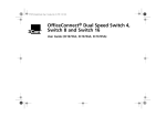
3Com
Ethernet Power Source
Guide
®
3C10220 - 12-Port Ethernet Power Source
3C10222 - 24-Port Ethernet Power Source
http://www.3com.com/
Part Number: 10038538-01 Rev B
Published: November 2000
3Com Corporation
5400 Bayfront Plaza
Santa Clara, California
95052-8145
Copyright © 2000, 3Com Corporation. All rights reserved. No part of this documentation may be reproduced
in any form or by any means or used to make any derivative work (such as translation, transformation, or
adaptation) without written permission from 3Com Corporation.
3Com Corporation reserves the right to revise this documentation and to make changes in content from time
to time without obligation on the part of 3Com Corporation to provide notification of such revision or change.
3Com Corporation provides this documentation without warranty, term, or condition of any kind, either
implied or expressed, including, but not limited to, the implied warranties, terms, or conditions of
merchantability, satisfactory quality, and fitness for a particular purpose. 3Com may make improvements or
changes in the product(s) and/or the program(s) described in this documentation at any time.
If there is any software on removable media described in this documentation, it is furnished under a license
agreement included with the product as a separate document, in the hardcopy documentation, or on the
removable media in a directory file named LICENSE.TXT or !LICENSE.TXT. If you are unable to locate a copy,
please contact 3Com and a copy will be provided to you.
UNITED STATES GOVERNMENT LEGEND
If you are a United States government agency, then this documentation and the software described herein are
provided to you subject to the following:
All technical data and computer software are commercial in nature and developed solely at private expense.
Software is delivered as “Commercial Computer Software” as defined in DFARS 252.227-7014 (June 1995) or
as a “commercial item” as defined in FAR 2.101(a) and as such is provided with only such rights as are
provided in 3Com’s standard commercial license for the Software. Technical data is provided with limited rights
only as provided in DFAR 252.227-7015 (Nov 1995) or FAR 52.227-14 (June 1987), whichever is applicable.
You agree not to remove or deface any portion of any legend provided on any licensed program or
documentation contained in, or delivered to you in conjunction with, this User Guide.
Unless otherwise indicated, 3Com registered trademarks are registered in the United States and may or may
not be registered in other countries.
3Com, the 3Com logo, AirConnect, and NBX are registered trademarks of 3Com Corporation.
All other company and product names may be trademarks of the respective companies with which they are
associated.
CONTENTS
ABOUT THIS GUIDE
Conventions 5
Documentation Comments
Year 2000 Compliance 6
3Com Support 7
1
6
3COM ETHERNET POWER SOURCE OVERVIEW
Overview 10
Features 10
Front Panel Connections and LEDs 11
10/100BASE-TX Data Input Ports 11
10/100BASE-TX Data and Power Output Ports
LEDs 12
Rear Panel Connections 14
Information Label 14
Console Port 14
DC Power Socket 15
AC Power Socket 15
Guidelines for Network Configuration 15
2
12
INSTALLING THE ETHERNET POWER SOURCE AND END DEVICES
Choosing a Suitable Site 20
Rack-mounting the EPS 21
Power-up Sequence 22
Adding Power 22
Verifying Correct Operation 22
Selecting the Correct Cables 22
Power Splitter Cable 24
Connecting an NBX Business Telephone 24
Connecting a 3Com Wireless Access Point 25
3
TROUBLESHOOTING
Solving EPS Problems 27
Solving NBX Telephone Problems 30
Solving Wireless Access Point Problems
A
32
SAFETY INFORMATION
Important Safety Information 36
L’information de Sécurité Importante 37
Wichtige Sicherheitsinformationen 39
B
TECHNICAL SPECIFICATIONS AND PIN ASSIGNMENTS
3COM CORPORATION LIMITED WARRANTY
ABOUT THIS GUIDE
This guide provides all the information that you need to install and use
either of the Ethernet Power Source (EPS) units:
■
3C10220 — with 12 10BASE-T/100BASE-TX ports
■
3C10222 — with 24 10BASE-T/100BASE-TX ports
The guide is intended for use by installers or network administrators who
are responsible for installing and setting up network equipment. It
assumes a basic working knowledge of LANs.
Conventions
Table 1 and Table 2 list conventions that are used throughout this guide.
Table 1 Notice Icons
Icon
Notice Type
Description
Information note
Information that describes important features or
instructions
Caution
Information that alerts you to potential loss of data or
potential damage to an application, system, network,
or device
Warning
Information that alerts you to potential personal injury
6
ABOUT THIS GUIDE
Table 2 Text Conventions
Convention
Description
Screen displays This typeface represents information as it appears on the
screen.
Commands
The word “command” means that you must enter the
command exactly as shown and then press Return or Enter.
Commands appear in bold.
The words “enter”
and “type”
When you see the word “enter” in this guide, you must type
something, and then press Return or Enter. Do not press
Return or Enter when an instruction simply says “type.”
Keyboard key names
If you must press two or more keys simultaneously, the key
names are linked with a plus sign (+). Example:
Press Ctrl+Alt+Del
Words in italics
Italics are used in this guide to:
■
Emphasize a point. For example: Do not run with scissors.
■
Denote a new term at the place where it is defined in the
text.
■
Identify menu names, menu commands, and software
button names. Examples:
From the Help menu, select Contents.
Click OK.
Documentation
Comments
Your suggestions are very important to us. They will help make our
documentation more useful for you. Please e-mail comments about this
guide to us at this address:
[email protected]
Please include the following information when you comment:
Year 2000
Compliance
■
3Com® Ethernet Power Source Guide
■
Part Number 10038538-01 Rev B
■
Page number
For information on Year 2000 compliance and 3Com products, visit the
3Com Year 2000 Web page:
http://www.3com.com/products/yr2000.html
3Com Support
3Com Support
For information about these topics:
■
Product Troubleshooting
■
Software Downloads
■
Documentation
■
3Com Service
use your web browser to access this web site:
http://support.3com.com/
and look for Network Telephony Products.
7
8
ABOUT THIS GUIDE
1
3COM ETHERNET POWER SOURCE
OVERVIEW
The 3Com Ethernet Power Source (EPS) provides power, over existing
Ethernet wiring, to devices such as NBX telephones and 3Com wireless
access points. The EPS can determine whether an Ethernet device can
accept power over the Ethernet cable, and supply power only to those
devices capable of accepting it.
The EPS:
■
Eliminates the need for AC outlets, Uninterrupted Power Supplies
(UPS), and AC/DC adapters
■
Can be used with the 3Com NBX 100 Communications System
business telephones and with 3Com’s wireless access points.
■
Is easy to add to your network
■
Allows you to manage power centrally
This chapter covers these topics:
■
Overview of the Ethernet Power Source
■
Front Panel Connections and LEDs
■
Rear Panel Connections
■
Guidelines for Network Configuration
10
CHAPTER 1: 3COM ETHERNET POWER SOURCE OVERVIEW
Overview
The power source is designed for use with a standard
10BASE-T/100BASE-TX Ethernet network over standard TIA/EIA-568,
Category 5 cable. The DC operating power for the data terminal units is
fed through the unused pairs (7/8) and (4/5).
You can order the EPS in either of these models:
Features
■
12 Ethernet ports
■
24 Ethernet ports
The EPS has the following hardware features:
■
Remote power feeding of Ethernet terminals
■
12 or 24 ports of combined 10BASE-T/100 BASE-TX data and power
■
Shielded RJ-45 input/output connectors
■
Universal 85-264VAC 50/60Hz input
■
Power feeding over 7/8 and 4/5 spare twisted pairs of Category 5
UTP/STP cable
■
Independent overload and short-circuit protection for each port
■
Port status LED indicators
■
Power on/off command for each port
■
RS-232 monitoring and control serial port
■
FLASH memory for field firmware upgrades
■
Standard 19” 1.5U rack mounting with hardware
■
–24 VDC connector for an external DC power supply
Front Panel Connections and LEDs
Front Panel
Connections and
LEDs
11
Figure 1 and Figure 2 show the front-panel details of the 24-port and
12-port EPS units. The LEDs are described in later in this section.
Figure 1 24-Port Ethernet Power Source — Front View
Note: Bottom row connectors are input ports (data only).
Top row connectors are output ports (data and power).
Figure 2 12-Port Ethernet Power Source — Front View
Note: Bottom row connectors are input ports (data only).
Top row connectors are output ports (data and power).
Both the 12-port (P/N 3C10220) and the 24-port (P/N 3C10222) versions
of the EPS have two rows of 10BASE-T/100BASE-TX ports. The input
ports, on the bottom row, are numbered from left to right (as you face
the front of the unit). Each output port is located immediately above the
input port to which it corresponds. You must use non crossover cables
with both input and output ports.
10/100BASE-TX
Data Input Ports
The EPS input ports (bottom row) accept Ethernet data only (Tx/Rx) over
the standard two wire pairs on an RJ-45 connector (Transmit on pins 1
and 2; Receive on pins 3 and 6).
12
CHAPTER 1: 3COM ETHERNET POWER SOURCE OVERVIEW
10/100BASE-TX
Data and Power
Output Ports
The EPS output ports (top row) carry two kinds of transmissions:
■
Ethernet data on the standard two wire pairs on an RJ-45 connector
(Transmit on pins 1 and 2; Receive on pins 3 and 6)
and
■
DC power on the previously unused wire pairs of the RJ-45 connector
(-24VDC Return on pins 4 and 5 and -24VDC on pins 7 and 8)
The maximum segment length from the switch or hub to the Network
Interface Card (NIC), including the EPS, is 100 m (328 ft.) using
Category 5 twisted pair cable.
LEDs
lists the lights (LEDs) on the front of the EPS and their states. For
information on using the LEDs for problem solving, see “Solving EPS
Problems” in Chapter 3.
Table 3 LED Behavior
Per-port Status Indications
Visual Indications (for Each Port) Port Status
Yellow LED
Green LED
Note: Do not automatically assume that a
yellow LED indicates a problem. For example, if
the yellow LED for any port is ON, the EPS is
not supplying power to that port/device, which
may indicate that the device is not capable of
accepting power via its Ethernet connection.
Off
On
■
Normal condition. Port power is turned on
and a device is drawing power from the
port.
Off
Off
■
Main power supply is off.
or
■
Port power is turned off.
or
■
Both main power and port power are on,
but no device cable is plugged into the
port.
On
Off
■
Either the device that is plugged into the
port is incapable of accepting power via its
Ethernet connection, or it has attempted to
draw too much power from the port. The
EPS has shut off the port power.
On
On
■
An internal fault has occurred on this port.
The EPS has shut off the port power.
Front Panel Connections and LEDs
13
Table 3 LED Behavior (continued)
Per-port Status Indications
Unit Power Status Indications
AC LED
DC LED
Off
Off
■
No AC power supply is plugged into the AC
inlet and no redundant DC power supply is
connected.
or
On
Off
■
An AC power supply fault has occurred and
no redundant DC power supply is
connected.
■
An AC power supply is plugged into the AC
inlet and no redundant DC power supply is
connected.
or
Off
On
■
An AC power supply is plugged into the AC
inlet, and a power failure has occurred on
the redundant DC power supply that is
connected.
■
An AC power supply is not plugged into AC
inlet and a redundant DC power supply is
connected.
or
On
On
■
A main power supply fault has occurred
and a redundant DC power supply is
connected.
■
An AC power supply is plugged into AC
inlet
and
■
A redundant DC supply is connected.
Self-Test Indications
TEST LED
Off
Normal condition
On
Self-test routine is in progress
14
CHAPTER 1: 3COM ETHERNET POWER SOURCE OVERVIEW
Rear Panel
Connections
Figure 3 shows the EPS rear panel.
Figure 3 Ethernet Power Source — Rear Panel
CONSOLE PORT
9600, 8, 1, N
DC INPUTS: 24Vdc/16Amp max.
ONLY FOR USE WITH SPECIFIED
POWER SUPPLY.
REFER TO INSTRUCTIONS MANUAL.
Power Source Unit
P/N ..................
S/N ..................
Information Label
Console Port
SUPPLY DATA
V~
Hz
100-120/200-240
60/50
A
3/1.5
Caution: Shock Potential. Disconnect
the Power Before Servicing.
To facilitate reporting any future problem, record here the Part Number
(P/N) and Serial Number (S/N) of the EPS from the unit information label
on the rear panel.
■
Part number: ______________________
■
Serial number: _____________________
Use the Console Port to connect a remote (or local) terminal and perform
remote (or local) management. This port does not carry Ethernet traffic.
The Console Port uses a standard null modem cable. The port settings are
fixed and have these values:
■
Baud Rate: 9600
■
Data Bits: 8
■
Parity: None
■
Stop Bit(s): 1
If you are upgrading the firmware on the EPS using a local computer
connected by a null modem cable, the upgrade program configures the
communications port that you select on your computer (COM1 is the
default) to match these settings.
You can obtain the firmware upgrade program and instructions for using
it from this web site:
http://support.3com.com/
Look for the Network Telephony Products area.
Guidelines for Network Configuration
DC Power Socket
15
The EPS has a 12-pin DC power socket for use only with an optional –24
VDC uninterruptible power supply (UPS). See the documentation that
comes with your UPS.
The EPS normally draws power from its internal power supplies. If an
external DC supply is connected, an electronic circuit in the EPS draws
power from either the internal or external supply to ensure steady power
delivery to the devices attached to the EPS output ports.
AC Power Socket
Guidelines for
Network
Configuration
The EPS adjusts to any supply voltage from 90 through 240V AC.
Design your network with these guidelines in mind:
■
In a typical application, the maximum UTP cable length is 100 m (328
ft.) using Category 5 cable (from the main switch or hub to the
far-end NIC device).
■
3Com recommends that you use a short UTP cable of 1 to 2 m (6 to 7
ft.) from the switch or hub to the EPS and a longer UTP cable of 1 to
90 m (3 to 300 ft.) from the EPS to the powered device such as the
NBX Business Telephone or a 3Com wireless access point.
Sample topologies are shown in Figure 4 and Figure 5.
16
CHAPTER 1: 3COM ETHERNET POWER SOURCE OVERVIEW
Figure 4 Sample EPS Topology with the NBX 100 Communications System
NBX 100
Switch or Hub
3Com Ethernet
Power Source
Wiring Closet
Patch Panel
Premises
Cabling
Wall
Jack
Guidelines for Network Configuration
Figure 5 Sample Network Topology with a 3Com Wireless Access Point
Servers
Switch or Hub
3Com Ethernet
Power Source
3Com Wireless
Access Point
Premises
Cabling
Laptop with
Wireless
PCM Card
Wiring Closet
Patch Panel
17
18
CHAPTER 1: 3COM ETHERNET POWER SOURCE OVERVIEW
2
INSTALLING THE
ETHERNET POWER SOURCE
AND END DEVICES
This chapter contains the information that you need to install and set up
the Ethernet Power Source (EPS) and end devices. The following topics
are described:
■
Choosing a Suitable Site
■
Rack-mounting the EPS
■
Power-up Sequence
■
Selecting the Correct Cables
■
Power Splitter Cable
■
Connecting an NBX Business Telephone
■
Connecting a 3Com Wireless Access Point
WARNING: Safety Information. Before you install or remove any
components from the Power Source unit or carry out any maintenance
procedures, you must read the safety information provided in Appendix A
of this guide.
AVERTISSEMENT: Consignes de sécurité. Avant d'installer ou d'enlever
tout composant du Power Source unit ou d'entamer une procédure de
maintenance, lisez les informations relatives à la sécurité qui se trouvent
dans l'Appendice A de ce guide.
WARNHINWEIS: Sicherheitsinformationen. Bevor Sie Komponenten
aus dem Power Source unit entfernen oder dem Power Source unit
hinzufuegen oder Instandhaltungsarbeiten verrichten, lesen Sie die
Sicherheitsanweisungen, die in Appendix A (Anhang A) in diesem
Handbuch aufgefuehrt sind.
20
CHAPTER 2: INSTALLING THE ETHERNET POWER SOURCE AND END DEVICES
Choosing a
Suitable Site
The EPS is suitable for an office environment. It can either be
rack-mounted in a standard 19-inch equipment rack (for example, in a
wiring closet or equipment room) or placed free-standing on a desk,
table, or counter. Both the 12-port and 24-port EPS packages (3C10220
and 3C10222 respectively) contain a rack-mounting kit with two
mounting brackets and six screws.
When you select a site for the EPS:
■
Always follow the appropriate configuration practices for Fast
Ethernet, including the 100-meter limit on total cable length.
■
Locate the EPS so that you can connect cables easily.
■
Locate cables away from sources of electrical noise such as:
■
Radios, transmitters, or broadband amplifiers
■
Power lines
■
Fluorescent lighting fixtures
■
Make sure that no water or moisture can enter the EPS case. The unit
is not designed for outdoor use.
■
Make sure that air can flow freely on all sides of the EPS for proper
cooling. 3Com recommends that you provide a minimum of 25 mm
(1 in.) clearance on each side of the unit.
■
If you use more than one EPS and place them on a table or desk, do
not place more than four units in a single stack. If you mount multiple
EPS units in a rack, this limit does not apply.
Rack-mounting the EPS
Rack-mounting the
EPS
21
The EPS is 1.5U high (1 U equals 3.8 cm (1.5 inches)) and fits in most
standard 19-inch equipment racks.
CAUTIONS:
■
Before you connect the brackets or mount the unit in the rack,
disconnect all cables and power from the EPS.
■
Verify that no self-adhesive pads are attached to the underside of the
unit.
1 Place the EPS upright on a hard, flat surface with the front facing you.
2 Place a mounting bracket over the mounting holes on one side of the
unit, as shown in Figure 6.
Figure 6 Fitting a Bracket for Rack Mounting
3 Insert the three screws and tighten with a suitable screwdriver (not
provided).
You must use the screws supplied with the mounting brackets. Damage
to the unit caused by using incorrect screws invalidates your warranty.
4 Repeat step 2 and step 3 for the other side of the EPS.
5 Insert the EPS into the 19-inch rack and secure it with suitable screws (not
provided). Ensure that nothing obstructs the ventilation holes.
6 Connect the network cabling.
22
CHAPTER 2: INSTALLING THE ETHERNET POWER SOURCE AND END DEVICES
Power-up Sequence
Adding Power
The following sections describe how to add power to your EPS and
prepare it for operation.
To add power to the EPS, follow these steps.
CAUTION: The EPS has no On/Off switch; the only way to connect or
disconnect the power is to insert or remove the power cord from the unit.
1 Insert the power cord that comes with the unit into the power socket on
the rear panel of the EPS.
2 Insert the other end of the power cord into the power outlet.
The EPS runs through a Power-On Self-Test (POST), which takes
approximately 10 seconds.
Verifying Correct
Operation
During the Power-On Self-Test, all ports on the EPS are disabled. The LEDs
light in this sequence:
■
All LEDs light for 2 seconds.
■
All LEDs turn off for 2 seconds.
■
AC power LED is continually lit.
■
All Port LEDs are ready with normal indications.
If you see other behavior in the LEDs, see “Solving EPS Problems” in
Chapter 3.
Selecting the Correct
Cables
Each of the input ports (the lower row of RJ45 connectors) on the front of
the EPS are configured as “route through” ports; that is, all 4 data wires
(pins 1,2,3 and 6) connect directly to the same data wires on the output
port directly above it (in the upper row of RJ45 connectors).
To make a connection to a powered MDI port, use a standard
straight-through cable, not a cross-over cable. The cable must include all
8 wires (4 pairs), as shown in Figure 7.
Selecting the Correct Cables
Figure 7 Connecting Other Devices to the Power Source Unit
1
2
3
4
5
6
7
8
RJ-IN
data
data
data
spare
spare
data
spare
spare
o e
ub
RJ-OUT
1
2
3
4
5
6
7
8
1
2
3
4
5
6
7
8
DTE/Splitter
data
data
data
DC +
data
DC -
1
2
3
4
5
6
7
8
RJ45
RJ45
Switch/Hub
Table 4 and Table 5 list the RJ45 input and output plugs (per port)
Table 4 RJ-45 Input Plug (per Port): Switch Side
Pin #
Label
Description
1
TX +
Tx data signal to switch or hub
2
TX –
Tx data signal to switch or hub
3
RX +
Rx data signal from switch or hub
4
Spare
Unused
5
Spare
Unused
6
RX –
Rx data signal from switch or hub
7
Spare
Unused
8
Spare
Unused
9
Shield
Connector shielding
Table 5 RJ-45 Output Plug (per Port): DTE (NIC) Side
Pin #
Label
Description
1
P_RX +
Rx Data Signal from DTE
2
P_RX –
Rx Data Signal from DTE
3
P_TX +
Tx Data Signal to DTE
4
–24Vdc_return (+)
Feeding power (+)
5
–24Vdc_return (+)
Feeding power (+)
6
P_TX –
Tx Data Signal to DTE
7
–24Vdc (–)
Feeding power (–)
8
–24Vdc (–)
Feeding power (–)
9
Shield
Connector shielding
23
24
CHAPTER 2: INSTALLING THE ETHERNET POWER SOURCE AND END DEVICES
Power Splitter
Cable
The power splitter cable has a single RJ45 female connector on one end.
All eight pins on this connector are connected, either to the power or to
data.
On the other end, the cable is split into two portions. The power plug
carries the –24VDC (and returns) from pins 4, 5, 7, and 8. The RJ45
carries the data signals (transmit and receive) on pins 1, 2, 3, and 6.
Connecting an NBX
Business Telephone
Figure 8 illustrates how to connect an NBX Business Telephone, using the
power splitter cable (3C10223: 12 pack). Follow these steps:
1 Before you attach any other cable to the female RJ45 connector on the
power splitter, insert the power splitter power plug into the power
receptacle on the telephone.
2 Plug the male RJ45 connector on the power splitter into the RJ45
receptacle on the telephone.
3 Using Category 5 cable that has been checked for continuity on all eight
wires, connect an EPS output port (a port on the upper row of
connectors) to the data jack closest to the telephone.
This connection may involve multiple segments such as the patch panel
and premises cabling shown in Figure 8. The total length of the
connection path should not exceed 100 meters.
See Figure 4 in Chapter 1 for a sample topology using the EPS and the
NBX 100 Business Telephone.
Figure 8 Connecting the EPS to an NBX Business Telephone
Ethernet Power Source
NBX Telephone
Wiring Closet
Patch Panel
Wall
Jack
Premises
Cabling
Splitter
Connecting a 3Com Wireless Access Point
25
4 After you make the final connection, check the LCD display on the
telephone. Information appears when the telephone attempts to
download information from the NBX system.
If you see nothing in the LCD display, see “Solving NBX Telephone
Problems” in Chapter 3.
Connecting a 3Com
Wireless Access
Point
Figure 9 shows how to connect a 3Com Wireless Access Point. You do
not need a power splitter for this end device.
See Figure 5 in Chapter 1 for a typical network topology with the EPS and
the 3Com Wireless Access Point.
Using Category 5 cable that has been checked for continuity on all eight
wires, connect an EPS output port (a port on the upper row of
connectors) to the data jack closest to the 3Com Wireless Access Point.
The connection may involve multiple segments such as the patch panel
and premises cabling shown in Figure 9. The total length of the
connection path should not exceed 100 meters.
Figure 9 Connecting the EPS to a 3Com Wireless Access Point
3Com Wireless
Access Point
Ethernet Power Source
Wiring Closet
Patch Panel
Premises
Cabling
26
CHAPTER 2: INSTALLING THE ETHERNET POWER SOURCE AND END DEVICES
When the connection is complete between the EPS and the 3Com
Wireless Access Point, verify that:
■
The power LED continues to flash until the Wireless Access Point
completes the bootstrap sequence.
■
The Power LED then stays illuminated.
If there is a connection to the Ethernet, the Ethernet status LED flashes.
If the Wireless Access Point LEDs do not light, refer to “Solving Wireless
Access Point Problems” in Chapter 3.
3
Solving EPS
Problems
TROUBLESHOOTING
If the LEDs on the EPS indicate a problem, see Table 6 for some suggested
solutions.
Table 6 Solving EPS Problems
Problem
Possible Cause
A Power LED does not Loose AC power
light, and you have NO cable
external DC voltage
supply.
Suggested Action
■
Verify that the power cable is firmly
connected to the EPS.
■
Verify that the other end of the
power cable is firmly connected to
the supply outlet.
No AC available
at outlet
■
If both of the connections are
secure and there is still no power to
the unit, verify (using a voltmeter or
some other device that uses AC
power) that power is available at
the AC outlet. If the outlet has no
power available, check for a
building power problem such as a
burned-out fuse or an open circuit
breaker.
Faulty power
cable
■
If power is available at the AC
outlet, but there is still no power to
the EPS, you may have a faulty
power cable. Substitute another
power cable.
Faulty EPS power
supply or faulty
LED
■
If the power cable is not faulty, you
may have a faulty power supply
within the EPS, or a faulty power
LED. Contact an authorized 3Com
Reseller.
28
CHAPTER 3: TROUBLESHOOTING
Table 6 Solving EPS Problems (continued)
Problem
Possible Cause
Suggested Action
A Power LED does not
light, and you have
both AC power and an
external DC voltage
supply.
Both AC power
and DC power
supplies are
faulty.
■
Disconnect the DC power supply,
and use the procedures outlined
earlier in this table to check for
problems with the AC supply.
■
If there are no AC supply problems,
disconnect AC power and connect
the DC supply. If the power LED
does not light, check for DC power
supply problems using the
procedures supplied by the DC
power supply vendor.
A device is connected, Faulty connection
but the Status LED for
the port does not light.
■
Verify that all connections are
secure.
No power to the
connected device
■
Verify that the device is receiving
power.
The device is not
capable of
accepting power
via the Ethernet
cable.
■
Check the device specification to be
sure that the device can accept
power via the Ethernet connection.
Faulty connection
■
Verify that all connections are
secure.
Faulty Ethernet
cable
■
Verify that the cables are not
twisted, corrupted, or shorted
together.
■
Verify that the cables properly
conduct the signals on pins 4, 5, 7,
and 8 from end to end.
■
Some Ethernet devices (for example,
some Network Interface Cards)
connect pins 4, 5, 7, and 8 to
earth/ground. If these pins are
grounded, the EPS senses the
excessive current, shuts off the port,
and lights the Overload LED. Verify
with the equipment supplier to
determine whether these pins are
grounded.
The Overload/Power
Not Available LED for
the port is Yellow.
The device cannot
accept power via
the Ethernet
connection.
Note: A yellow LED indicates only that
the EPS has shut off power to the port.
This is a normal condition that causes
no harm to either the device or the EPS.
Solving EPS Problems
29
Table 6 Solving EPS Problems (continued)
Problem
Possible Cause
Suggested Action
The device was
connected too
soon after being
disconnected.
■
If the cables do not appear to be a
problem, and pins 4, 5, 7, and 8 are
not grounded, the end device may
have been plugged in too soon after
being unplugged, which can result
in the device appearing to the EPS
as a nonpowered device. Unplug
the device cable from the EPS port,
wait for 15 seconds, and then plug
it back in. This pause gives the
electronic circuits in the device time
to fully discharge.
If none of these procedures identifies the problem, contact an authorized 3Com
service representative for additional assistance.
30
CHAPTER 3: TROUBLESHOOTING
Solving NBX
Telephone
Problems
If power is not reaching an NBX Business Telephone, use the information
in Table 7 to resolve the problem.
Table 7 Solving NBX Business Telephone Problems
Problem
Possible Cause
No characters appear in
Faulty connection
the telephone LCD display.
The telephone may
be faulty.
Suggested Action
■
Verify all physical connections.
■
Supply power to the
telephone using the standard
external adapter that comes
with the telephone. If any
characters appear in the LCD
display, the telephone is not
faulty.
Note: You do not need to
connect the telephone to the
Ethernet to perform this check.
Faulty Ethernet
cable between the
telephone and the
wall jack
■
Take the telephone and the
Ethernet cable to the EPS
location and connect the
telephone directly to an EPS
output port (one of the top
row of connectors).
■
If information does not appear
in the LCD display, replace the
Ethernet patch cable, being
sure to use one that is wired
for all eight pins.
Note: If information appears in
the LCD display, the EPS,
telephone, power splitter, and
Ethernet patch cable are fully
functional.
Faulty EPS port
■
Plug the telephone into
another EPS output port.
Faulty power
splitter
■
Replace the power splitter.
Faulty connection
between the wall
jack and the EPS
■
Verify that the Ethernet wall
jack is connected to the EPS. If
that is not the source of the
problem, check the cables and
connections between the wall
jack and the EPS.
Solving NBX Telephone Problems
31
Table 7 Solving NBX Business Telephone Problems (continued)
Problem
Possible Cause
Suggested Action
Faulty EPS
■
Follow the procedures
described in Table 6 to
determine if the EPS is faulty.
■
Check all connections
between the telephone and
the NBX chassis (patch cables,
premises wiring, hubs, and
switches)
The NBX NCP is not
operating properly.
■
Check other telephones. If
they are working properly, the
NCP is functioning properly.
The telephone has
lost connection to
the Network
Control Processor.
■
If the date and time appear in
the LCD display, the telephone
previously had a connection to
the NCP, but that connection
has been lost. Verify all
physical connections between
the telephone and the NCP
(patch cables, premises wiring,
hubs, and switches).
The NBX NCP is not
operating properly.
■
Check other telephones. If
they are working properly, the
NCP is functioning properly.
Telephone receives power, Faulty connection
but date and time do not to the NBX
appear in the LCD display. Network Control
Processor (NCP) in
the NBX chassis.
Telephone receives power,
date and time appear in
the LCD display, but
telephone does not
operate properly.
If none of these procedures identifies the problem, contact an authorized 3Com
service representative for additional assistance.
32
CHAPTER 3: TROUBLESHOOTING
Solving Wireless
Access Point
Problems
If power is not reaching a Wireless Access Point, use the information in
Table 8 to resolve the problem.
Table 8 Solving Wireless Access Point Problems
Problem
Possible Cause
Suggested Action
No power to the Wireless
Access Point
Faulty physical
connection
■
Verify all physical connections
between the Wireless Access
Point and the EPS.
The Wireless
Access Point may
be faulty.
■
Supply power to the Wireless
Access Point using the
standard external adapter that
was supplied with the unit. If
any of the LEDs light up, the
Wireless Access Point is not
faulty.
Note: You do not need to
connect the Wireless Access Point
to the Ethernet to perform this
check.
Faulty Ethernet
cable between the
Wireless Access
Point and the wall
jack
■
Take the Wireless Access Point
and the Ethernet patch cable
to the EPS location and
connect the Wireless Access
Point directly to an EPS output
port (one of the top row of
connectors).
■
If the Wireless Access Point
LEDs do not light up, replace
the Ethernet cable, being sure
to use one that is wired for all
eight pins.
Note: If the LEDS light up, the
EPS, Wireless Access Point, and
Ethernet patch cable are fully
functional.
Faulty EPS port
■
Plug the Wireless Access Point
into another EPS output port.
Faulty connection
between the wall
jack and the EPS
■
Verify that the Ethernet wall
jack is connected to the EPS. If
that is not the problem, verify
the cables and connections
between the wall jack and the
EPS.
Solving Wireless Access Point Problems
33
Table 8 Solving Wireless Access Point Problems (continued)
Problem
Possible Cause
Suggested Action
Faulty EPS
■
Follow the procedures
described in Table 6 to
determine if the EPS is faulty.
■
Check all physical connections
between the Wireless Access
Point and the LAN (network).
Check patch panels, premises
wiring, hubs, and switches.
The Wireless Access Point is Faulty network
receiving power, but the
connection
network indicator (center
LED) does not flash.
If none of these procedures identifies the problem, contact an authorized 3Com
service representative for additional assistance.
34
CHAPTER 3: TROUBLESHOOTING
A
SAFETY INFORMATION
Carefully read and follow this safety information before you install or
remove any components or perform any maintenance procedures on the
Ethernet Power Source (EPS).
WARNING: Warnings contain directions that you must follow for your
personal safety. Follow all directions carefully. You must read the
following safety information carefully before you install or remove the
unit.
AVERTISSEMENT: Les avertissements présentent des consignes que vous
devez respecter pour garantir votre sécurité personnelle. Vous devez
respecter attentivement toutes les consignes. Nous vous demandons de
lire attentivement les consignes suivantes de sécurité avant d’installer ou
de retirer l’appareil.
WARNHINWEIS: Warnhinweise enthalten Anweisungen, die Sie zu Ihrer
eigenen Sicherheit befolgen müssen. Alle Anweisungen sind sorgfältig zu
befolgen. Sie müssen die folgenden Sicherheitsinformationen’ sorgfältig
durchlesen, bevor Sie das Gerät installieren oder ausbauen.
36
APPENDIX A: SAFETY INFORMATION
Important Safety
Information
■
Installation and removal of the EPS must be carried out by qualified
personnel only.
■
Always connect the EPS to an earth (ground) connection when you
connect it to an AC outlet (power supply).
■
To comply with European safety standards, the EPS must always be
connected to an earthed (grounded) outlet.
■
The power cord set must be approved for the country in which it is
used, as indicated in Table 9.
Table 9 International Safety Information
U.S.A. and
Canada
■
The cord set must be UL-approved and CSA certified.
■
The flexible cord must meet these minimum specifications:
— No. 18 AWG
— Type SV or SJ
— 3-conductor
■
The cord set must have a rated current capacity of at least
10A.
■
The attachment plug must be an earth-grounding type
with a NEMA 5-15P (15A, 125V) or NEMA 6-15P
(15A, 250V) configuration.
Denmark
■
The supply plug must comply with section 107-2-D1,
standard DK2-1a or DK2-5a.
Switzerland
■
The supply plug must comply with SEV/ASE 1011.
■
The appliance coupler (which is the connector to the unit, not to the
wall) must have a configuration for mating with an EN60320/IEC320
appliance inlet.
■
The socket outlet must be near to the unit and easily accessible. You
can remove power from the unit only by disconnecting the power
cord from the outlet.
■
This unit operates under SELV (Safety Extra Low Voltage) conditions
according to IEC 950. These conditions are maintained only if the
equipment to which it is connected also operates under SELV
conditions.
■
Switzerland only:
– The supply plug must comply with SEV/ASE 1011.
L’information de Sécurité Importante
■
37
France and Peru only:
– This unit cannot be powered from IT (impédance à la terre) supplies.
If your supplies are of IT type, this unit must be powered by 230V
(2P+T) via an isolation transformer ratio 1:1, with the secondary
connection point labelled Neutral, connected directly to earth
(ground).
■
U.K. only:
– The EPS is covered by Oftel General Approval, S/G/12345/J/100003,
for indirect connection to a public telecommunications system. This
connection can only be achieved using the Console Port on the unit
and an approved modem.
WARNING: The RJ45 ports are shielded RJ45 data sockets. They cannot
be used as telephone sockets. Connect only RJ45 data connectors to
these sockets.
3Com suggests that you use unshielded data cables with unshielded jacks
when making connections to these data sockets.
L’information de
Sécurité Importante
■
L'installation et la dépose de ce groupe doivent être confiés à un
personnel qualifié.
■
Si vous entassez l'unité Power Source avec les unités SuperStack II
Hub, l'unité Ethernet Power Source (EPS) doit être installée en dessous
des unités Hub plus étroites.
■
L’unité ne devrait pas etre branchee a une prise de courant C.A.
(source de courant) sous aucun prétexte sans un branchement mise à
la terre (mise à la masse).
■
Vous devez raccorder ce groupe à une sortie mise à la terre (mise à la
masse) afin de respecter les normes européennes de sécurité.
■
Le coupleur d'appareil (le connecteur du groupe et non pas la prise
murale) doit respecter une configuration qui permet un branchement
sur une entrée d'appareil EN60320/CEI 320.
■
La prise secteur doit se trouver à proximité de l’appareil et son accès
doit être facile. Vous ne pouvez mettre l’appareil hors circuit qu'en
débranchant son cordon électrique au niveau de cette prise.
■
L’appareil fonctionne à une tension extrêmement basse de sécurité qui
est conforme à la norme CEI 950. Ces conditions ne sont maintenues
38
APPENDIX A: SAFETY INFORMATION
que si l'équipement auquel il est raccordé fonctionne dans les mêmes
conditions.
■
Cordon électrique — Il doit être agréé dans le pays d'utilisation:
Table 10 Sécurité Importante
Etats-Unis et
Canada
■
Le cordon doit avoir reçu l'homologation des UL et un
certificat de la CSA.
■
Le cordon souple doit respecter, à titre minimum, les
spécifications suivantes :
calibre 18 AWG
type SV ou 5J
à 3 conducteurs
■
Le cordon doit être en mesure d'acheminer un courant
nominal d'au moins 10 A.
■
La prise femelle de branchement doit être du type à mise à la
terre (mise à la masse) et respecter la configuration NEMA
5-15P (15 A, 125 V) ou NEMA 6-15P (15 A, 250 V).
Danemark
■
La prise mâle d'alimentation doit respecter la section 107-2
D1 de la norme DK2 1a ou DK2 5a.
Suisse
■
La prise mâle d'alimentation doit respecter la norme SEV/ASE
1011.
■
France et Pérou uniquement:
Ce groupe ne peut pas être alimenté par un dispositif à impédance à
la terre. Si vos alimentations sont du type impédance à la terre, ce
groupe doit être alimenté par une tension de 230 V (2 P+T) par le biais
d'un transformateur d'isolement à rapport 1:1, avec un point
secondaire de connexion portant l'appellation Neutre et avec
raccordement direct à la terre (masse).
AVERTISSEMENT: Les ports RJ45. Il s'agit de prises femelles blindées de
données RJ45. Vous ne pouvez pas les utiliser comme prise de téléphone.
Branchez uniquement des connecteurs de données RJ45 sur ces prises
femelles.
Les câbles de données blindés ou non blindés, avec les jacks blindés ou
non blindés, l'un ou l'autre, peuvent être branchés à ces prises de courant
de données.
Wichtige Sicherheitsinformationen
Wichtige Sicherheitsinformationen
39
■
Die Installation und der Ausbau des Geräts darf nur durch
Fachpersonal erfolgen.
■
Wenn die Ethernet Power Source (EPS) Einheit in einer Stapel mit
anderen SuperStack II Hub Einheiten eingebaut werden soll, muß die
EPS Einheit unter die schmaleren Hub Einheiten eingebaut werden.
■
Das Gerät ist unter keinen umständen an einen Wechselstrom (A.C.)
Netzstecker anzuschließen ohne erdungsleitung.
■
Das Gerät muß an eine geerdete Steckdose angeschlossen werden,
die die europäischen Sicherheitsnormen erfüllt.
■
Der Anschlußkabelsatz muß mit den Bestimmungen des Landes
übereinstimmen, in dem er verwendet werden soll.
■
Der Gerätestecker (der Anschluß an das Gerät, nicht der
Wandsteckdosenstecker) muß eine passende Konfiguration für einen
Geräteeingang gemäß EN60320/IEC320 haben.
■
Die Netzsteckdose muß in der Nähe des Geräts und leicht zugänglich
sein. Die Stromversorgung des Geräts kann nur durch Herausziehen
des Gerätenetzkabels aus der Netzsteckdose unterbrochen werden.
■
Der Betrieb dieses Geräts erfolgt unter den SELV-Bedingungen
(Sicherheitskleinstspannung) gemäß IEC 950. Diese Bedingungen sind
nur gegeben, wenn auch die an das Gerät angeschlossenen Geräte
unter SELV-Bedingungen betrieben werden.
WARNHINWEIS: RJ45 Ports. RJ45-Anschlüsse. Dies sind abgeschirmte
RJ45-Datenbuchsen. Sie können nicht als Telefonanschlußbuchsen
verwendet werden. An diesen Buchsen dürfen nur RJ45-Datenstecker
angeschlossen werden.
Diese Datenstecker können entweder mit abgeschirmten oder
unabgeschirmten Datenkabeln mit abgeschirmten oder unabgeschirmten
Klinkensteckern verbunden werden.
40
APPENDIX A: SAFETY INFORMATION
B
TECHNICAL SPECIFICATIONS AND
PIN ASSIGNMENTS
Table 11 Technical Specifications for the Ethernet Power Source
Physical Dimensions
Height: 76 mm (3.0 in.) x Width: 483 mm (19.0 in.) x Depth: 300 mm (12.0 in.)
Weight: 5kg (10.8lbs)
Environmental Requirements
Operating Temperature
0° to 50°C (32° to 122°F)
Storage Temperature
10° to +70°C (14° to 158°F)
Operating Humidity
10 to 95% relative humidity, noncondensing
Standards
EN60068 (IEC68)
Safety
Agency Certifications
UL 1950, EN60950, CSA 22.2 No. 950, IEC 950
EMC
Emissions
EN55022 Class B*, FCC Part 15 subpart B Class A, ICES-003 Class A,
VCCI Class B*, AS/NZS 3548 Class B*, CNS 13438 Class A
* You must use Category 5 screened cables to ensure compliance with the
Class B requirements of these standards. The use of unscreened cables (category
3 or 5 for 10BASE-T ports or category 5 for 100BASE-TX ports) complies with
Class A requirements.
Immunity
EN50082-1
Heat Dissipation
75 watts maximum (255 BTU/hour maximum)
Power Supply
AC Line Frequency
50Hz
60Hz
Input Voltage Options
200 - 240 VAC
100 -120 VAC
Current Rating
5 amps (maximum)
42
APPENDIX B: TECHNICAL SPECIFICATIONS AND PIN ASSIGNMENTS
Pin assignments are the same for the 10BASE-T and 100BASE-TX RJ45
connectors.
Table 12 Pin Assignments
Pin Number
Signal
Function
Input Ports (Data + Power)
1
RxData +
Receive data from DTE / NIC
2
RxData –
Receive data from DTE / NIC
3
TxData +
Transmit data to DTE / NIC
4
– 24vDC +
Positive signal feeding
5
– 24vDC +
Positive signal feeding
6
TxData –
Transmit data to DTE / NIC
7
– 24vDC (–)
Return signal feeding
8
– 24vDC (–)
Return signal feeding
1
TxData +
Transmit data to switch
2
TxData –
Transmit data to switch
3
RxData +
Receive data from switch
4
Not assigned
Terminated
5
Not assigned
Terminated
6
RxData –
Receive data from switch
7
Not assigned
Terminated
8
Not assigned
Terminated
Input Ports (Data only)
3Com Corporation LIMITED WARRANTY
3COM ETHERNET POWER SOURCE 12-PORT UNIT (3C10220) AND 24-PORT UNIT (3C10222)
HARDWARE
3Com warrants this hardware product to be free from defects in workmanship and materials, under normal
use and service, for the following length of time from the date of purchase from 3Com or its authorized
reseller: Lifetime
3Com’s sole obligation under this express warranty shall be, at 3Com’s option and expense, to repair the
defective product or part, deliver to Customer an equivalent product or part to replace the defective item, or
if neither of the two foregoing options is reasonably available, 3Com may, in its sole discretion, refund to
Customer the purchase price paid for the defective product. All products that are replaced will become the
property of 3Com. Replacement products may be new or reconditioned. 3Com warrants any replaced or
repaired product or part for ninety (90) days from shipment, or the remainder of the initial warranty period,
whichever is longer.
SOFTWARE
3Com warrants that each software program licensed from it will perform in substantial conformance to its
program specifications, for a period of ninety (90) days from the date of purchase from 3Com or its
authorized reseller. 3Com warrants the media containing software against failure during the warranty period.
No updates are provided. 3Com's sole obligation under this express warranty shall be, at 3Com's option and
expense, to refund the purchase price paid by Customer for any defective software product, or to replace any
defective media with software which substantially conforms to applicable 3Com published specifications.
Customer assumes responsibility for the selection of the appropriate applications program and associated
reference materials. 3Com makes no warranty or representation that its software products will meet
Customer’s requirements or work in combination with any hardware or applications software products
provided by third parties, that the operation of the software products will be uninterrupted or error free, or
that all defects in the software products will be corrected. For any third-party products listed in the 3Com
software product documentation or specifications as being compatible, 3Com will make reasonable efforts to
provide compatibility, except where the non-compatibility is caused by a "bug" or defect in the third party's
product or from use of the software product not in accordance with 3Com’s published specifications or user
manual.
YEAR 2000 WARRANTY
In addition to the Hardware Warranty and Software Warranty stated above, 3Com warrants that each
product sold or licensed to Customer on and after January 1, 1998 that is date sensitive will continue
performing properly with regard to such date data on and after January 1, 2000, provided that all other
products used by Customer in connection or combination with the 3Com product, including hardware,
software, and firmware, accurately exchange date data with the 3Com product, with the exception of those
products identified at 3Com’s Web site, http://www.3com.com/products/yr2000.html, as not meeting this
standard. If it appears that any product that is stated to meet this standard does not perform properly with
regard to such date data on and after January 1, 2000, and Customer notifies 3Com before the later of April
1, 2000, or ninety (90) days after purchase of the product from 3Com or its authorized reseller, 3Com shall,
at its option and expense, provide a software update which would effect the proper performance of such
product, repair such product, deliver to Customer an equivalent product to replace such product, or if none
of the foregoing is feasible, refund to Customer the purchase price paid for such product.
Any software update or replaced or repaired product will carry a Year 2000 Warranty for ninety (90) days
after purchase or until April 1, 2000, whichever is later.
OBTAINING WARRANTY
SERVICE
Customer must contact a 3Com Corporate Service Center or an Authorized 3Com Service Center within the
applicable warranty period to obtain warranty service authorization. Dated proof of purchase from 3Com or
its authorized reseller may be required. Products returned to 3Com's Corporate Service Center must be
pre-authorized by 3Com with a Return Material Authorization (RMA) number marked on the outside of the
package, and sent prepaid and packaged appropriately for safe shipment, and it is recommended that they
be insured or sent by a method that provides for tracking of the package. The repaired or replaced item will
be shipped to Customer, at 3Com's expense, not later than thirty (30) days after 3Com receives the defective
product.
Dead- or Defective-on-Arrival. In the event a product completely fails to function or exhibits a defect in
materials or workmanship within the first forty-eight (48) hours of installation but no later than thirty (30)
days after the date of purchase, and this is verified by 3Com, it will be considered dead- or
defective-on-arrival (DOA) and a replacement shall be provided by advance replacement. The replacement
product will normally be shipped not later than three (3) business days after 3Com’s verification of the DOA
product, but may be delayed due to export or import procedures. When an advance replacement is provided
and Customer fails to return the original product to 3Com within fifteen (15) days after shipment of the
replacement, 3Com will charge Customer for the replacement product, at list price.
3Com shall not be responsible for any software, firmware, information, or memory data of Customer
contained in, stored on, or integrated with any products returned to 3Com for repair, whether under
warranty or not.
WARRANTIES EXCLUSIVE
IF A 3COM PRODUCT DOES NOT OPERATE AS WARRANTED ABOVE, CUSTOMER'S SOLE REMEDY FOR
BREACH OF THAT WARRANTY SHALL BE REPAIR, REPLACEMENT, OR REFUND OF THE PURCHASE PRICE
PAID, AT 3COM'S OPTION. TO THE FULL EXTENT ALLOWED BY LAW, THE FOREGOING WARRANTIES AND
REMEDIES ARE EXCLUSIVE AND ARE IN LIEU OF ALL OTHER WARRANTIES, TERMS, OR CONDITIONS,
EXPRESS OR IMPLIED, EITHER IN FACT OR BY OPERATION OF LAW, STATUTORY OR OTHERWISE, INCLUDING
WARRANTIES, TERMS, OR CONDITIONS OF MERCHANTABILITY, FITNESS FOR A PARTICULAR PURPOSE,
SATISFACTORY QUALITY, CORRESPONDENCE WITH DESCRIPTION, AND NON-INFRINGEMENT, ALL OF
WHICH ARE EXPRESSLY DISCLAIMED. 3COM NEITHER ASSUMES NOR AUTHORIZES ANY OTHER PERSON TO
ASSUME FOR IT ANY OTHER LIABILITY IN CONNECTION WITH THE SALE, INSTALLATION, MAINTENANCE OR
USE OF ITS PRODUCTS.
3COM SHALL NOT BE LIABLE UNDER THIS WARRANTY IF ITS TESTING AND EXAMINATION DISCLOSE THAT
THE ALLEGED DEFECT OR MALFUNCTION IN THE PRODUCT DOES NOT EXIST OR WAS CAUSED BY
CUSTOMER'S OR ANY THIRD PERSON'S MISUSE, NEGLECT, IMPROPER INSTALLATION OR TESTING, UNAUTHORIZED ATTEMPTS TO OPEN, REPAIR OR MODIFY THE PRODUCT, OR ANY OTHER CAUSE BEYOND THE
RANGE OF THE INTENDED USE, OR BY ACCIDENT, FIRE, LIGHTNING, OTHER HAZARDS, OR ACTS OF GOD.
LIMITATION OF LIABILITY
TO THE FULL EXTENT ALLOWED BY LAW, 3COM ALSO EXCLUDES FOR ITSELF AND ITS SUPPLIERS ANY
LIABILITY, WHETHER BASED IN CONTRACT OR TORT (INCLUDING NEGLIGENCE), FOR INCIDENTAL,
CONSEQUENTIAL, INDIRECT, SPECIAL, OR PUNITIVE DAMAGES OF ANY KIND, OR FOR LOSS OF REVENUE OR
PROFITS, LOSS OF BUSINESS, LOSS OF INFORMATION OR DATA, OR OTHER FINANCIAL LOSS ARISING OUT
OF OR IN CONNECTION WITH THE SALE, INSTALLATION, MAINTENANCE, USE, PERFORMANCE, FAILURE, OR
INTERRUPTION OF ITS PRODUCTS, EVEN IF 3COM OR ITS AUTHORIZED RESELLER HAS BEEN ADVISED OF THE
POSSIBILITY OF SUCH DAMAGES, AND LIMITS ITS LIABILITY TO REPAIR, REPLACEMENT, OR REFUND OF THE
PURCHASE PRICE PAID, AT 3COM'S OPTION. THIS DISCLAIMER OF LIABILITY FOR DAMAGES WILL NOT BE
AFFECTED IF ANY REMEDY PROVIDED HEREIN SHALL FAIL OF ITS ESSENTIAL PURPOSE.
DISCLAIMER
Some countries, states, or provinces do not allow the exclusion or limitation of implied warranties or the
limitation of incidental or consequential damages for certain products supplied to consumers, or the
limitation of liability for personal injury, so the above limitations and exclusions may be limited in their
application to you. When the implied warranties are not allowed to be excluded in their entirety, they will be
limited to the duration of the applicable written warranty. This warranty gives you specific legal rights which
may vary depending on local law.
GOVERNING LAW
This Limited Warranty shall be governed by the laws of the State of California, U.S.A. excluding its conflicts of
laws principles and excluding the United Nations Convention on Contracts for the International Sale of
Goods.
3Com Corporation
5400 Bayfront Plaza
Santa Clara, CA 95054
(408) 326-5000