1
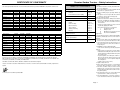
2005DEC09
Countax Garden Tractors - Safety Instructions
CERTIFICATE OF CONFORMITY
Training
I, the undersigned Adam Bennett of Countax Limited, Great Haseley, Oxford, ENGLAND certify that the lawnmowers:
Model: C Series
C300M
C30H
C300H
C400H
C600H
C800H
C600-4WD
C800-4WD
9.32
9.69
9.69
10.44
11.93
13.42
11.93
13.42
Engine operating speed
2800rpm
3000rpm
3000rpm
3000rpm
3000rpm
3000rpm
3000rpm
3000rpm
Engine manufacturer
Briggs &
Stratton
Honda
Honda
Honda
Honda
Honda
Honda
Honda
Engine type
Petrol
Petrol
Petrol
Petrol
Petrol
Petrol
Petrol
Petrol
Mass in kg
241
241
241
243
244
261
264
Max drawbar pull (kg) at
coupling hook
400
400
400
400
400
400
Max sound power level
98db(A)
99db(A)
99db(A)
100db(A)
100db(A)
Max rear axle weight (kg)
250
250
250
250
Vibration (m/s/s) Hands
2.76
2.76
2.76
Vibration (m/s/s) Seat
0.76
0.76
Type of cutting device
Cutterbar
92cm
Power (kW)
Std width of cutting device
TABLE OF CONTENTS
Safety Instructions
Page 1
Operating Instructions
Page 2
Controls
Page 3-6
Powered Grass Collector (PGC)
Page 7
Using Your Countax Tractor
Page 8-9
281
Routine Maintenance
Page 10-12
400
400
Trouble Shooting:
100db(A)
100db(A)
100db(A)
250
250
250
250
2.76
2.76
2.76
2.76
2.76
0.76
0.76
0.76
0.76
0.76
0.76
Cutterbar
Cutterbar
Cutterbar
Cutterbar
Cutterbar
Cutterbar
Cutterbar
92cm
92cm
97cm
107cm
122cm
107cm
122cm
Cutting
Page 13
Cutter Levelling
Page 14-15
Grass Collecting
Page 16
Tyres & Wheels
Page 17
Starting & Running
Page 18
Electrics
Page 19
Supplementary Instructions
Model: A Series
Power (kW)
A25/50HE
14.91
14.91
18.63
C Series Specifications
Page 21
A Series Specifications
Page 22
Personal Service Records
Page 23
3000rpm
3000rpm
3000rpm
Honda
Honda
Kawasaki
Engine type
Petrol
Petrol
Petrol
Mass in kg
290
290
295
Max drawbar pull (kg) at
coupling hook
400
400
400
Max sound power level
104db(A)
104db(A)
104db(A)
Max rear axle weight (kg)
250
250
250
Vibration (m/s/s) Hands
2.76
2.76
2.76
Vibration (m/s/s) Seat
0.53
0.53
0.53
Type of cutting device
Cutterbar
Cutterbar
Cutterbar
127cm
127cm
127cm
Std width of cutting device
Page 20
A20/50HE
Engine manufacturer
Engine operating speed
for Manual Tractors
A20/50H
Conforms to the specification of Directive 84/538/EEC (as adapted to the technical progress by Directive 88/180/
EEC and Directive 89/392/EEC (amended by 91/368/EEC, 93/44/EEC and 93/31/EEC) and Directive 89/336/EEC and
amended by 91/263/EEC, 92/31/EEC) and 2000/14/EC.
Standards used: BS5107, EN292, ISO3767, ISO3864 Tested at Oxford, England.
1. Read the instructions carefully. Be familiar with controls and
the use of equipment.
2. Never allow children or people unfamiliar with these
instructions to operate the mower.
3. Never mow while people, especially children or pets, are
nearby.
4. The operator or user is responsible for accidents or hazards
occurring to other people or their property.
5. Do not carry passengers.
6. All drivers should seek to obtain professional and practical
instruction. In addition the following should be noted:
• The need for care and concentration when working with
this machine.
• Control of a tractor sliding on a slope; control will not be
regained by applying the brake.
• The main reasons for loss of control are:
i.
Insufficient wheel grip
ii.
Driving too fast
iii.
Operating on steep slopes (max 15º)
iv.
Incorrect load distribution
Preparation
1. Check that the machine complies with all applicable
regulations, including those in force when used on the public
highway.
2. When mowing, always wear substantial footwear and long
trousers. Do not operate when barefoot or with sandals.
3. Thoroughly inspect the area where the tractor is to be used
and remove all stones, sticks, wires and bones or any other
foreign objects.
4. WARNING – petrol is highly flammable:
• Store fuel in containers specifically designed for this
purpose.
• Refuel outdoors only and do not smoke while refuelling.
• Add fuel before starting the engine. Never remove the cap
from the fuel tank or add petrol while the engine is running or
when engine is hot.
• If petrol is spilled, do not attempt to start the engine
but move the machine away from the area of spillage and
avoid creating any source of ignition until petrol vapours
have dissipated.
• Replace the fuel cap securely.
5. Replace faulty silencers.
I declare on behalf of Countax Limited that these machines conform to EC Essential Health and Safety requirements.
Signed:
6. Before using, always inspect to see that the blades,
bolts and cutter assembly are not worn or damaged.
7. Check the condition of the tyres and ensure that they are
inflated to the correct pressures (refer to page 14). This
is particularly important if the machine is to be taken on
the public highway.
A. Bennett (Technical Director) 01/01/2002
8. Check that the mower is in good working order, paying
special attention to brakes and steering.
9. Check that all linkages, connections and pivot nuts are
secure and that the wheel nuts are tightened correctly.
Page 1
Countax Garden Tractors - Personal Service Record
Countax Garden Tractors - Operating Instructions
Safety
1. Read the instructions carefully. Be familiar with controls
and the use of equipment.
2. Do not operate the engine in a confined space where
dangerous fumes can collect.
3. Mow only in daylight or in very good artificial light.
4. Before starting the engine, disengage blade and attach
ment drives and shift into neutral.
5. Take care on slopes - maximum 15º for 2WD and 25º on
4WD models. On no account should slopes steeper than
25º be driven on.
6. Remember, there is no such thing as a ‘safe slope’.
Travel on grass slopes requires particular care to guard
against overturning:
• Do not stop or start suddenly when going up or
downhill.
• Engage drive slowly. Always keep the machine in drive
when travelling up or down a slope.
• Machine speed should be kept low on slopes and in
tight turns.
• Stay alert for humps and hollows and other hidden
hazards.
• Avoid mowing across the face of a slope.
7. Watch out for traffic when crossing or working near road
ways.
8. Stop the blades rotating before crossing roadways.
9. When using the machine, never direct discharge or mate
rial towards bystanders or allow anyone near the machine
while in operation.
10. Never operate the mower with defective guards, shields
or without protective safety devices in place and in good
working order.
11.Do not change governor settings to increase the revs
of the engine. Operating an engine at excessive speed
increases the risk of injury.
12. Before leaving the operators position:
• Disengage the drive to the cutter blades and attach
ments, then lower the attachments.
• Apply the Parking Brake (change into neutral first – on
manual tractor).
• Stop the engine and remove the ignition key.
13. Always disengage drive to attachments, stop the engine
and disconnect the spark plug lead or remove the
ignition key before:
• Cleaning blockages.
• Checking, cleaning or working on the mower.
• Refuelling.
• Removing the Grass Collector.
Also: • After striking a foreign object inspect the
mower for damage and make any repairs before
restarting the tractor.
• If the machine starts to vibrate abnormally, check
immediately and call your dealer if necessary.
14. Disengage drive to attachments when transporting or not
in use.
15. Reduce the throttle setting during engine run-out.
16. Never work on the mower when the engine is running.
Always: • Use good common sense at all times and to
ensure this tractor is safe and serviceable fit
only original manufacturers supplied spares.
• Inspect the area to be cut, note the
position of any stumps, manhole covers, bumps
or depressions and avoid them to prevent
damaging the blades.
• Ensure the fuel tank is full before you start the
machine.
We recommend the use of STANDARD UNLEADED fuel.
• Disconnect both battery terminals before
attempting any work in the engine compartment.
Never • Leave the tractor unattended and running.
• Put hands near moving blades, belts or the Power
Take-Off pulley while they are rotating.
Powered Grass Collector (PGC)
PGC Tipping Lever*
Cutting Height Adjustment Lever*
PGC Connection Lever
Model
Date of Purchase
Date of Registration
Name of Dealer
Serial Number
1st First Service (12 months)
4th Fourth Service (48 months)
DEALER STAMP
OR NAME & ADDRESS
Service Date:
Hours:
DEALER STAMP
OR NAME & ADDRESS
Service Date:
Dealer’s Signature:
Dealer’s Signature:
2nd Second Service (24 months)
5th
DEALER STAMP
OR NAME & ADDRESS
Service Date:
Power Take-Off (PTO) Engage Lever
PGC Lift Lever*
Use this page as a personal record of the service history of your Countax garden tractor. Ask your dealer to stamp the appropriate box at the same time as your Service Record Card.
Hours:
Hours:
Fifth Service (60 months)
DEALER STAMP
OR NAME & ADDRESS
Service Date:
Hours:
Dealer’s Signature:
Dealer’s Signature:
3rd Third Service (36 months)
6th Sixth Service (72 months)
Tractor Drive Pedals
DEALER STAMP
OR NAME & ADDRESS
Service Date:
PGC Net
Cutter Deck
Collector Height Adjustment Lever
Page 2
Anti-scalp Wheel
* Where fitted
Dealer’s Signature:
Hours:
DEALER STAMP
OR NAME & ADDRESS
Service Date:
Dealer’s Signature:
Page 23
Hours:
Countax Garden Tractors – A Series Specification
Countax Garden Tractors – Operating Instructions, Controls
Seat Adjustment (Figure 1)
Weight
A20/50H PGC Capacity
Turning Radius
The seat on your Countax tractor is adjustable forward and
backward to suit the operator. Simply lift the seat latch at the
front of the seat and slide the seat forward or backward as
appropriate. Always ensure the seat is latched back into position before driving off.
A20/50H
290 kg
300 litres
99cm
A20/50HE
290 kg
A20/50HE PGC Capacity
Forward Speeds
A25/50HE
290 kg
390 litres
0-7 mph
A20/50HE PGC 68 kg
A25/50HE PGC Capacity
Tyre Pressures
Ignition (Figure 2 & 11)
A25/50HE PGC 68 kg
390 litres
Front: 0.8-1.1 KGF/cm (12-16 psi)
Fuel Tank Capacity
Transmission
Rear: 0.43-0.7 KGF/cm (6-10 psi)
7 litres (1.5 gallons)
Tuff Torq K62 Hydrostatic
The “key start” controls both the ignition and the starter. The
engine cannot be started without the park brake being on;
the “P” light (Figure 11 - C) indicates the brake is engaged.
Insert the key and turn to the first position, then turn further
to activate the starter. Release when the engine starts. To
stop the engine, turn the key to the left (having first switched
off both the cutter and Power Take-off). To prevent unauthorised use, always remove the key after use. THE IGNITION
MUST ALWAYS BE TURNED OFF BEFORE THE TRACTOR
CAN BE RE-STARTED.
A20/50H PGC 59 kg
A20/50H: 2.72m; A20/50HE and A25/50HE: 2.87m
1m
Figure 1
1.84m
Choke (Figure 3)
1.19m
An independent choke is fitted to some models. This choke
should be used in conjunction with a fast throttle setting
when starting the engine from cold. It should be cancelled
as soon as possible. Do not use the choke when starting a
warm engine.
Figure 2
Figure 3
Engine Speed Control (Figure 4)
The lever is pushed up for FAST(
) and down for SLOW
(
). On some models the choke control is above the fast
setting, a cold engine is started on the Choke setting, a
warm one on the FAST setting. The Choke setting should be
cancelled as soon as possible. The engine should be operated on the FAST setting at all times.
Model
Engine
Displacement
Power
Torque
Bore
Stroke
A20/50H
Honda Twin
Cylinder OHV 90º
V-Twin 14.91kW
614cc
14.91kW 20hp
44.1NM
77mm
66mm
A20/50HE
Honda Twin
Cylinder OHV 90º
V-Twin 14.91kW
614cc
14.91kW 20hp
44.1NM
77mm
66mm
A25/50HE
Kawasaki Twin
Cylinder V-Twin
18.64kW
614cc
18.64kW 25hp
44.1NM
77mm
66mm
RPM Meter (Figure 5)
Hour Meter (Figure 5)
M / MIN
Your tractor is fitted with an hour meter to assist you in
adhering to the recommended service intervals. The hour
meter only operates whilst the engine is actually running.
We recommend that your garden tractor is serviced after
50 hours of use or yearly, whichever comes first.
Service intervals are preset into the PCB memory and will
flash up ‘S’ on the park brake display before the service is
due. This will be reset by your dealer.
Note: 50 hours of mowing at 5 mph equates to 250 miles
of grass cutting !
Page 22
Figure 4
The RPM monitor on the electronic display indicates the
engine speed. This feature should be used when the cutter
deck is engaged and in conjunction with the forward speed.
To ensure complete cutting and collection the engine speed
should not be allowed to fall below 2600rpm, the display will
flash should this happen. If, when in use, the display does
flash and the engine speed drops below 2600rpm, there are
two options: a) Reduce forward speed b) Raise the cutting
height.
Page 3
Figure 5
Countax Garden Tractors – Operating Instructions, Controls
Drive Controls - Hydrostatic (Figure 6)
Figure 6
The forward speed of the tractor is controlled by footpedal
‘A’. Reversing is controlled by footpedal ‘B’.
Moving Off / Reversing (Figure 6 & 7)
Pedal A
To move off, ensure your feet are off pedals ‘A’ and ‘B’ and
then release the parking brake by pushing the hand lever
‘C’ (figure 7, page 4) to the forward position. Now gently
depress pedal ‘A’ and you will move off. The further you
depress pedal ‘A’ the faster you will go. Its function is similar
to that of a car accelerator except that it controls the hydrostatic transmission and does not affect the speed of the
engine. To reverse simply depress pedal ‘B’ and the tractor
will begin to reverse. As with the forward pedal, the speed of
reversing is increased as the pedal is pushed further.
Countax Garden Tractors – C Series Specification
Weight
7 litres (1.5 gallons)
2WD 63.5cm
4WD 77cm
PGC Capacity
Forward Speeds
300 litres
0-6 mph
Transmission
Tyre Pressures
Tuff Torq K46 Hydrostatic or
Peerless MST 206/536A Transaxle or
Front: 0.8-1.1 KGF/cm (12-16 psi)
Rear: 0.7-1.1 KGF/cm (10-12 psi)
Fuel Tank Capacity
C300-Mulcher
C600-Mulcher
C300M
C300H
C30H
C400H
C600H
C800H
C600-4WD
C800-4WD
PGC
241 kg
244 kg
241 kg
241 kg
241 kg
243 kg
244 kg
261 kg
264 kg
281 kg
59 kg
Transmission 4WD
Tuff Torq K57 & HFWD
Turning Radius
Pedal B
2.72m (2WD) 2.85m (4WD)
0.93m
Stopping
1.75m (2WD) 1.88m (4WD)
To stop the tractor simply release either pedal ‘A’ or ‘B’ and
the natural braking of the hydrostatic system will bring the
tractor to a stand still. For smooth braking release either
pedal gradually, for an emergency stop remove foot rapidly.
1.12m
Parking (Figure 6 & 7)
Remove your foot from pedals ‘A’ and ‘B’ (as you would stop
normally) and then simply pull the parking brake lever ‘C’ to
the upright position - a “P” will be indicated on the dashboard display (Page 5 Figure 11 (C)). When you turn off the
engine, the natural braking of the hydrostatic system will add
to the effect of the brake. It’s like leaving your car in gear.
Lever C
Figure 7
Neutral Valve (Figure 8)
The natural braking of hydrostatic transmission means that it
is not possible to easily push or freewheel the tractor. To
disengage, first make certain that the machine is on a flat
even surface. Release the parking brake by moving the
handbrake lever forward ‘C’. Locate the C Series Neutral
Valve, situated alongside the rear right wheel or the
A Series, alongside the rear left wheel. Disengage by pulling
out the lever. You will now be able to push the tractor at a
speed not exceeding 2 mph. Make sure you disengage the
Neutral Valve by pushing the lever back BEFORE starting
your tractor.
C Series Position
A Series Position
Figure 8
Differential Lock - A Series (Figure 9)
The A Series is fitted with a differential lock for maximum
traction on slopes and slippery ground. The differential lock
should only be used in situations where one wheel is slipping
and the other is not. In a situation when one wheel starts to
slip and extra traction is required simply depress pedal ‘D’
(Figure 9) and the differential will lock both wheels to drive
at the same speed. Immediately the differential lock is not
required release the engage pedal ‘D’ and as soon as the
wheels are rotating at the same speed and not under load
(i.e. on a slope) the lock will automatically release.
Pedal D
Figure 9
Important - DO NOT ATTEMPT TO STEER THE TRACTOR
OUT OF A STRAIGHT LINE WHILST THE DIFF LOCK IS
ENGAGED.
Page 4
Model
Engine
Displacement
Power
Torque
Bore
Stroke
C300
Mulcher
Honda Twin Cylinder
OHC 90º V-Twin
9.69kW
530cc
9.69kW 13hp
35.9NM
77mm
57mm
C600
Mulcher
Honda Twin Cylinder
OHC 90º V-Twin
11.93kW
530cc
11.93kW 16hp
36.5NM
77mm
57mm
C300M
Briggs & Stratton
Single Cylinder
INTEK 9.32kW
465cc
9.32kW 12.5hp
24.5NM
87.3mm
66mm
C30H
Honda Single
Cylinder OHV
9.69kW
???cc
9.69kW 13hp
???NM
??mm
??mm
C300H
Honda Twin Cylinder
OHC 90º V-Twin
9.69kW
530cc
9.69kW 13hp
35.9NM
77mm
57mm
C400H
Honda Twin Cylinder
OHC 90º V-Twin
10.44kW
530cc
10.44kW 14hp
35.9NM
77mm
57mm
C600H
Honda Twin Cylinder
OHC 90º V-Twin
11.93kW
530cc
11.93kW 16hp
36.5NM
77mm
57mm
C800H
Honda Twin Cylinder
OHC 90º V-Twin
13.42kW
614cc
13.42kW 18hp
44.1NM
77mm
66mm
C600-4WD
Honda Twin Cylinder
OHC 90º V-Twin
11.93kW
530cc
11.93kW 16hp
36.5NM
77mm
57mm
C600-4WD
Honda Twin Cylinder
OHC 90º V-Twin
13.42kW
614cc
13.42kW 18hp
44.1NM
77mm
66mm
Page 21
Countax Garden Tractors - Supplementary Manual Tractor Instructions
Drive Controls - Manual Gears (Figure 53 & 54)
Figure 53
If your tractor is fitted with a manual transmission, the six
forward speeds and reverse are controlled manually via a
control lever to the right of the driver. A pedal to the right of
the console controls the brake and clutch.
Moving Off/Reversing (Figure 53 & 54)
The tractor can be driven off in any of the forward gears,
with each number representing a speed that the tractor can
travel at (e.g. 1=SLOW, 6=FAST).
Depress and hold the Brake/Clutch pedal (Figure 53), move
the Gear Select Lever to the required gear (Figure 54) then
SLOWLY release the pedal to engage drive to the wheels of
your tractor. The machine MUST ALWAYS be at a standstill
before you change the lever settings to a different speed.
Cutter On/Off Switch (Figure 10 & 11)
The cutter switch controls the electromagnetic blade clutch.
To switch the cutter on, push the switch and then release it,
this will engage the cutter deck. To indicate that the Cutter
Deck is engaged, the Cutter Deck Indicator will flash (Figure
11 - A). To stop the Cutter Deck, push the switch again.
Although the Cutter Deck is automatically switched off when
the engine is stopped or when the operator gets off the seat,
it is not good practice to rely on these features, the Cutter
Deck should always be switched OFF as soon as you have
finished cutting and certainly BEFORE stopping the engine
or getting off the tractor. The Cutter will only work whilst the
operator is sat on the seat.
Should your tractor be fitted with 4WD it will have ESA. This
is set to an angle of 25 degrees at the factory. If this angle
is exceeded then the display will flash 250 and a warning
siren will sound.
For smooth braking depress the Brake/Clutch pedal
gradually, for an emergency stop depress foot rapidly.
Parking (Figure 53 & 55)
To park, depress the Brake/Clutch pedal, then push and hold
down the Parking Brake. Release the footpedal, the Park
Brake should then be locked in position. To release the Park
Brake simply depress the Brake/Clutch footpedal and the
Park Brake will spring off.
Figure 54
The exceptional traction of 4WD will allow you to cut in very
slippery conditions, and it also allows the tractor to ascend
very steep slopes. If the slope alarm sounds DO NOT
attempt to cut or drive at a greater angle than the one you
are on. As all terrains and conditions vary, great care should
be maintained when operating the tractor. DO NOT take the
tractor into an area where it could become unstable.
B
C
A
Figure 11
On no account should slopes steeper than 250 be driven on.
Figure 55
Cutting Height Lever - Manual Lift Tractors
(Figure 12)
To engage the PTO, push the lever down and to the left and
release lever upwards. The PTO lever is pushed down and to
the right into its locator to disengage. Always have this lever
in the ‘disengaged’ position when it is not in use. DO NOT
PUT HANDS NEAR MOVING PULLEYS AND BELTS.
Parking Brake
Figure 11d
The Cutter Height Lever is located at the right hand side
on the rear body. The height is simply adjusted by pushing
DOWN for a lower cut or pulling UP for a higher cut. There
are 10 possible cutting heights, which are represented by
numbers with 1 being LOW. We recommend that positions
3 or 4 are used for mowing lawns and 8 or 9 for very long
grass and paddocks. When mowing in wet conditions it is
advisable to select a slightly higher cutting position than
would normally be used.
Electric Lifts (where fitted) - (Figure 13 & 11A)
Figure 12
DIAL-A-HEIGHT
The cutting height is adjusted by turning the rotary switch
anti-clockwise to lower the deck and clockwise to raise the
deck. The height indicator on the electronic display (Figure
11 - A) shows the deck position (0-lowest to 9-highest).
To get the best from this refinement use it to continuously
adjust cutting height to suit ground and grass conditions.
Do not make downward adjustments on the move until you
are familiar with the height control, this will avoid “scalping”
the lawn.
Figure 56
Page 20
Figure 10
Electronic Slope Alert (ESA) (Figure 11d)
Stopping (Figure 53)
Power Take-Off (PTO) Manual Tractors
(Figure 56)
Countax Garden Tractors - Operating Instructions, Controls
Page 5
Figure 13
Countax Garden Tractors - Operating Instructions, Controls
Electric Lifts (where fitted) - (Figure 14 & 15)
Countax Garden Tractors- Troubleshooting (Electrical)
NET EMPTY
Emptying the Powered Grass Collector is achieved by
pressing a switch (Figure 15) on the dashboard UP to open, DOWN to close.
Figure 14
Using the lever (figure 16) raise or lower the Powered Grass
Collector to either the Transport position or the Collecting
position.
Power Take-Off - C Series (Figure 17A)
10
10 AMP
LIGHTS
10 AMP FUEL SOLENOID /
PTO WIRE / HE LOOM RELAY
IF THE ELECTRIC SWEEPER LIFT FAILS TO OPERATE
CHECK:
4
Fuse 7 on the Fuse Holder (green 30amp fuse) has
not blown (Figure 52C)
Figure 52A
SPARE
C Series Fuse Box
10
10
10
10
20
20
If “C” Appears in the Park Brake Window for
more than 2 minutes.
20 AMP
CHARGE
This indicates that the battery is not charging.
CHECK:
4
The main charge fuse has not blown (Figure 52A,B,C)
20 AMP
IGNITION
Transport Position
Figure 16
Power Take-Off - A Series (Figure 17B)
To engage the PTO, push the lever down and to the left and
release lever upwards. The PTO lever is pushed down and to
the right into its locator to disengage. Always have this lever
in the ‘disengaged’ position when it is not in use. DO NOT
PUT HANDS NEAR MOVING PULLEYS AND BELTS.
SPARE
IF THIS IS NOT THE CASE CONTACT YOUR TRACTOR
DEALER.
To engage the PTO drive, the PTO lever is lifted up and out
of its locator and then moved to the left and released to
find its own height. To disengage the PTO pull the lever up
and to the right. Always have this lever in the ‘disengaged’
position when it is not in use. DO NOT PUT HANDS NEAR
MOVING PULLEYS AND BELTS.
Using the lever (figure 16) raise or lower the Powered Grass
Collector.
SPARE
10 AMP
CLUTCH
Figure 15
Collecting Position
10
20 AMP
CHARGE
20 AMP
IGNITION
IF THIS IS NOT THE CASE CONTACT YOUR TRACTOR
DEALER.
Manual PGC Lift Lever (Figure 16)
10
CHECK:
4
Fuse 6 on the Fuse Holder (red 10amp fuse) has
not blown (Figure 52B).
4
That nothing is caught between the deck and the
chassis.
20
AUXILIARY LIFT
Raising the Auxiliary (Grass Collector) Lift is achieved by
pressing a switch (Figure 14) on the dashboard - UP to raise,
DOWN to lower.
20
If the Electric Deck Lift on Your Tractor Fails to
Operate:
10 AMP
CLUTCH
IF THIS IS NOT THE CASE CONTACT YOUR TRACTOR
DEALER
Figure 17B
SPARE
10 AMP
LIGHTS
Figure 52B
Figure 17A
SPARE
10 AMP Deck Lift
10 AMP FUEL SOLENOID /
PTO WIRE / HE LOOM RELAY Models with Dial-a-height
Pressing the rocker switch turns ON the headlights. Turn
the headlights OFF by pressing the rocker switch again.
The headlights will not operate without the ignition switch
turned on.
30
10
10
10
10
Lights (Figure 18)
20
20
Figure 51
20 AMP
CHARGE
20 AMP
IGNITION
10 AMP
CLUTCH
Figure 52C
10 AMP
LIGHTS
10 AMP FUEL SOLENOID /
PTO WIRE / HE LOOM RELAY
C Series Fuse Box Location
Figure 18
Page 6
Page 19
SPARE
30 AMP
SWEEPER LIFT
10 AMP DECK LIFT
Models with Dial-a-height
and PGC electric lift
Countax Garden Tractors - Troubleshooting (Starting & Running)
Engine Fails to Turn Over:
CHECK:
4
That the brake is depressed or the parking brake is on
and that you are sitting on the seat.
4
That the battery terminals are connected (Page 10).
4
That fuse 2 (yellow 20amp ignition fuse) has not blown
or been dislodged.
4
That the battery is charged.
Figure 49
If The Engine Misfires, Loses Power or Stalls in
Use:
CHECK:
4
That you have not run out of fuel.
4
That the Air Filter Pre-cleaner is not blocked (see
Engine – Air and Cooling).
4
That the cooling air intakes are not blocked.
4
If the ignition lights have gone off – check yellow
20amp fuse, fuse 2 on the fuse holder.
4
That fuse 5 (red, 10amp) has not blown or been
dislodged.
IF THIS IS NOT THE CASE CONTACT YOUR TRACTOR
DEALER.
Position X
Fit the Net as shown in Figure 21 with the net rod in position
‘X’. To remove the net, release the net rod and secure in the
removal position ‘Y’.
When removing the net, we suggest you employ the assistance of another person.
1.
Partially open the PGC net (100mm (4”)). Disconnect
opening rod by pulling back on sprung locking tube
and uncoupling from pin. Repeat other side.
2.
Undo net locking clip (both sides), unhook levers from
locating pins.
3.
With one person standing each side of the collector
net, slide the net off the locating arms.
4.
Reverse operation for fitting.
If the Engine Turns Over and Does Not Start:
IF THIS IS NOT THE CASE CONTACT YOUR TRACTOR
DEALER.
Fitting the Net - C Series & A20/50H (Figure 19)
Fitting the Net - A20/50HE (Figure 20)
IF THIS IS NOT THE CASE CONTACT YOUR TRACTOR
DEALER.
CHECK:
4
That the fuel tank is full and the Petrol Tap is
turned ON (if fitted).
4
That the Spark Plug Lead is connected.
4
That the outlet in the fuel tank is not blocked.
4
That the Spark Plug is clean and set to the correct
gap (see engine manufacturer’s handbook for relevant
spark plug data).
4
That the Fuel Filter is not blocked (see Engine – Air
and Cooling).
4
That fuse 5 (red, 10amp) has not blown or been
dislodged.
Countax Garden Tractors - Operating Instructions, Powered Grass Collector
Net Rod
Position Y
Figure 19
Locating Lever
Locking Clip
Net Rod
PGC Connection (Figure 21)
Figure 50
To connect the Powered Grass Collector (PGC) to the tractor, ensure that both are on an even surface with the locking
levers on the collector facing the Lift Arms on the tractor.
Lift the seat and the PTO flap so that both are resting in the
upright position. Move the Collector manually to the tractor;
lower the lift arms using the lift lever. Locate the collector
channels with the Lift Arms and push until it stops at its limit.
Securing Pin
Installing the Drive Belt (Figure 22)
Place the drive belt over the PTO pulley of the Powered
Grass Collector, and then feed it underneath the PTO flap.
The lower half is pulled left and under the Belt Hook then fed
around the PTO pulley. Be sure that this is installed the right
way round otherwise the brush will work in reverse and
collection will be poor. Lock the Locating Lever over the Lift
Arm Lugs (this also tightens the PTO Drive Belt). Rotate
the Locking Clips over the Locating Lugs to securely lock
the Powered Collector in place. To disconnect, reverse this
procedure. ALWAYS CHECK BELT TENSION IS 19mm
DEFLECTION AT 2KGs PRESSURE. REFER TO PAGE 12
FOR ADJUSTMENT INSTRUCTIONS.
A20/50HE NET ASSEMBLY
Figure 20
Lift Arm
Lugs
Collector
Channels
Locking
Lever
If the Cutter Deck Fails to Operate:
Locking
Clips
CHECK:
4
That fuse 3 on the Fuse Holder (red 10amp Clutch
fuse) has not blown (page 19)
4
Whether you have got off the seat – the safety switch
will disengage the cutter.
4
The battery has lost charge and will no longer hold the
clutch in operation.
Figure 21
IF THIS IS NOT THE CASE CONTACT YOUR TRACTOR
DEALER.
Figure 22
Low Fuel Warning (Figure 50)
Belt Hook
When the petrol gets low on your tractor a warning will
appear on the dash next to the fuel picture to tell you to fill
up again as the tractor is about to run out of petrol.
Page 18
Page 7
Countax Garden Tractors - Using your Countax tractor
Connecting Net Empty Socket - A20/50HE
(Figure 23)
Countax Garden Tractors - Troubleshooting (Tyres & Wheels)
Persistent Flat Tyres
Figure 23
Connect Net Empty Plug to socket as shown in Figure 23.
This plug MUST BE FITTED before attempting to use your
Powered Grass Collector.
Adjusting the Sweeper Height (Figure 24)
Using the sweeper Height Lever select the position appropriate to the conditions and the height of cut. TO GET THE
BEST SWEEPING PERFORMANCE AND TO PRESERVE
THE BRUSHES SELECT THE HIGHEST SETTING THAT
WORKS - start high and adjust down until the brushes start
to collect (normally the middle adjustment hole). Do not set
the brushes too low - this will lead to scarifying and a very
untidy finish as well as shortening brush life.
The rim of the wheel has been damaged causing the seal
on the tube-less tyre to be broken. There are two solutions:
4
If the damage is not severe, treat with Countax Tyre
Sealant (Pt No. 52903501).
4
If the damage is significant it is necessary to order a
new wheel from your dealer.
If you have Hawthorn, Blackthorn or Wild Rose in your
garden – this will puncture any tyre. It makes sense to check
any area you intend to cut or drive over and to remove any
branches. THE LONG-TERM SOLUTION IS TO TREAT ALL
FOUR TYRES WITH COUNTAX TYRE SEALANT –
FOLLOW THE INSTRUCTIONS ON THE BOTTLE.
IF YOUR TYRES SPIN OR LOSE GRIP CHECK:
4
That all tyres are inflated to there correct pressures
(see page 21).
4
Are you going too fast for the conditions?
To Tip Cuttings - C Series & A20/50H (Figure 25)
When the collector is full, raise the collector to the transport
position. Drive to your tipping area, reverse to the grass pile,
and select neutral if the tractor is manual. Then extend the
tipping lever and pull it towards the seating position. This
pivots the collector and so empties the collector. Once the
grass is off-loaded return the collector to the upright position
and put the tipping lever in its original position.
To Tip Cuttings - A20/50HE (Figure 14 & 15)
You can check the contents of the PGC through the clear
cover. When it is full, raise the Collector to the transport
position (Page 6, Figure 14). Drive to your tipping area,
reverse to the pile, then depress then PGC Net Empty
Switch (Page 6, Figure 15).
Figure 46
This is an inevitable problem faced by around 5% of
Countax users. Like all garden machinery, the most common
cause of punctures are THORNS! Blackthorn, Hawthorn and
Rose are usually at the bottom of the problem and will puncture any tyre not fitted with very expensive guards. There
are less expensive ways to overcome this problem and it is
advisable to check and avoid these possible causes:
Removal of Front Wheel (Figure 46)
Figure 24
Standard Grass Collection
When cutting the grass and collecting follow these simple
steps:
1
Always run the engine at maximum speed.
2.
Lower the sweeper to the working postion.
RememberTO GET THE BEST SWEEPING PERFORMANCE
AND TO PRESERVE THE BRUSHES SELECT THE
HIGHEST SETTING THAT WORKS.
3.
Engage the sweeper drive.
4.
Engage the cutter deck drive.
5.
Lower the deck to the desired height of cut.
6.
Drive forward at a speed that does not cause the
engine speed to drop. REMEMBER if the RPM display
flashes below 2600rpm, there are two options: a)
Reduce forward speed b) Raise the cutting height.
Sometimes when cutting long grass or a paddock, it may be
better to cut the grass and disperse the clippings directly to
the ground. Alternatively remove collector net, fit the deflector accessory and spread the cut grass prior to final collection.
4
4
Apply Parking Brake.
Place chocks under the wheels that are to remain on
the ground.
4
Remove the plastic hubcap.
4
Use a 19mm socket/spanner to loosen the wheel nut
whilst on the ground – DO NOT REMOVE.
4
Place a jack under the front axle at the jacking point
Figure 46 (on the side appropriate to the wheel that is
to be removed). Jack the tractor up until the wheel to
be removed is well clear of the ground.
4
Remove the wheel nut and washer and keep safe.
4
Taking care not to dislodge the tractor from the jack,
pull the wheel off.
When the tyre is repaired, replace the wheel preferably using
a new M12 Nyloc nut (Part No. 04822400). Tighten to a
torque setting of 5.25Kg.m (38lb/ft).
Check to ensure wheel turns freely.
Figure 47
Figure 48
Figure 25
Removal of Rear Wheel (Figure 47 & 48)
4
4
4
4
4
4
Page 8
Under the
Chassis
Apply Parking Brake.
Place chocks under the wheels that are to remain
on the ground.
Loosen the the four wheel nuts.
Place a jack under the jacking point shown in Figure
47 (on the side appropriate to the wheel that is to be
removed). Jack the tractor up until the wheel to be
removed is well clear of the ground.
Remove the wheel nuts using a 19mm spanner/socket.
Once removed, keep safe and remove the wheel.
When replacing the wheel re-tighten the nuts to
5.25kg.m (38lb/ft).
Page 17
Countax Garden Tractors - Troubleshooting (Grass Collecting)
Countax Garden Tractors - Mulch Mowing
Grass Collection
Mulch Mowing
If your Collector appears to be not picking up satisfactorily,
check the following:
4
The PTO lever is engaged.
4
That the PTO pulley beneath the seat is turning –
if not, call your dealer.
4
That the Collector Belt is not reversed (if it is correct,
the brush revolves against the forward direction of the
tractor (Figure 45).
4
That the Brush Height Adjustment Lever is not set too
high or too low.
4
That there is not a build up of congealed grass on the
leading edge of the Brush Guard.
4
That the Brush is not clogged.
4
That the Collector Belt is not slipping, if it is then
adjust the tension or replace the worn or damaged belt.
See Page 11.
4
That the Collector net is not clogged. If so, wash or
brush with a stiff hand brush.
4
That the Brush is not damaged.
Mulching can save time, avoids creating piles of rotting
cuttings and feeds your lawn. When Mulch mowing it is
necessary to observe certain rules:
If you are still experiencing difficulties with collection please
contact your dealer.
1.
2.
3.
4.
5.
Figure 45
6.
7.
to
8.
Figure 26A
Reduce the height of the grass by no more than 1/3rd
its height in each pass. If the grass has grown long
make several passes to achieve the cut height you
require.
Run the engine at maximum speed.
Mow often, particularly in spring and early summer.
Short clippings of 25mm (1”) or less decompose
more quickly.
If an unsightly residue of cuttings is being left –
increase the cutting height.
Drive forward at a speed that does not cause the
engine speed to drop. REMEMBER if the RPM display
flashes below 2600rpm, there are two options: a)
Reduce forward speed b) Raise the cutting height.
Vary the mowing pattern from cut to cut.
Always keep the underside of the cutting deck clean
ensure good grass flow.
Always check that the blades are sharp and in good
condition – never attempt to sharpen or replace them
yourself. New Countax blades are not expensive; it is
good practice to ask your dealer to change them.
Figure 26B
High Grass Mulch Deck - (Figure 26B)
The real alternative when cutting long or paddock grass is
the “high grass mulch” deck. When using the high grass
mulch deck please ensure the following:
1.
2.
3.
Page 16
When cutting very tall grass set the deck at the higher
settings 7-9.
Drive forward at a speed that does not cause the
engine speed to drop. REMEMBER if the RPM display
flashes below 2600rpm, there are two options: a)
Reduce forward speed b) Raise the cutting height.
Regularly check the cutter deck drive belt tension in
accordance with the instructions (page 11).
Page 9
Figure 27
Countax Garden Tractors - Routine Maintenance
Countax Garden Tractors - Troubleshooting (Cutter Levelling)
Levelling Side to Side
Engine Maintenance
Please refer to the engine manufacturer’s handbook
enclosed with this manual.
Battery Maintenance (Figure 28)
The battery fitted to your tractor is a low maintenance sealed
unit. Should your battery require charging for any reason
please note that sealed lead acid batteries require a special
2 stage charging unit. Any battery charged on a standard
battery charger will fail prematurely. Your dealer will be
able to supply a battery charger specifically designed for the
battery fitted to your tractor. The battery charger part
number is 449563000. If your tractor does not start, refer to
the troubleshooting section in this manual.
Cutter Deck Maintenance
Figure 28
The battery in your Countax garden tractor is very similar to that found in
your car. To remove, simply undo the NEGATIVE terminal connection,
followed by the positive.
REMOVAL OF CUTTER DECK (Figures 29, 30, 31 & 32)
The Cutter Deck can be quickly removed for servicing or
cleaning, or to give greater clearance when driving or towing
over uneven ground.
Figure 29
Follow this sequence:
1.
Lower the cutting deck to its lowest position
(see Controls - Page 5).
2.
De-tension the Cutter Drive Belt with the lever under
the left running board (Figure 29).
3.
Remove the 3 securing pins from the front of the deck
(Figure 30 - A, B & C) by undoing the Rue Clips
(Figures 31 & 32) and removing them.
4.
Remove the 2 securing pins from the back of the deck
(Figure 30 - D and E).
5.
Slip the cutter drive belt off the Engine Pulley.
6.
Slide the deck out.
7.
If you are going to use the tractor without the deck,
remove the Securing Bar (Figure 30 - F).
8.
Remove the fifth wheel - G (A Series tractors only).
De-Tensioned
Tensioned
Front of tractor
D
C
Tractors up to serial No. 41130
This adjustment is best done with the deck in a position three up
from its lowest cut – check the level both sides and levelling is then
achieved by adjusting the left side ( as you are sat on the Tractor)
of the deck at 2 points.
REAR ADJUSTMENT (Figure 42 or 43)
1.
Find the Deck Level Disc (Figure 42 or 43) near the
back (near side) wheel. This has a concentric slot in
which the Deck Levelling Rod is located.
2.
Using a 13mm spanner, loosen the M8 Nyloc nut (A)
securing this stud just enough to permit some
movement.
3.
Now lift or depress the Deck depending on the
adjustment you wish to achieve. This will move the
stud up or down the disc – the higher up and
nearer the centre of the disc the higher the deck.
4.
Check with your ruler or tape and having levelled the
Deck at the rear, re-tighten the Nyloc nut.
FRONT ADJUSTMENT (Figure 44)
1.
Having levelled the rear of the Deck, check if the front
is level. If not, find the Deck Adjustment Plate
(Figure 44) which is forward of the Cutter Deck near
the front (left) wheel.
2.
Before making adjustments, loosen the two sets of
nuts and bolts (A & B).
3.
Using a 13mm spanner, loosen (upper) locknut (C).
4.
Now adjust the height by using a ratchet or spanner to
turn the Nyloc nut (D) clockwise (up) to raise the Deck
or anti-clockwise (down) to lower it.
5.
When level is achieved, tighten lock nut (C), re-tighten
nuts and bolts A & B.
6.
Raise and lower the cutter deck and then re-check
level.
A
B
Figure 42
A20/50HE tractor
A
B
Figure 43
A
C
D
B
Figure 44
Manual Deck Lift
DECK LEVEL SYSTEM FOR ‘C’ SERIES
F
C Series & A20/50H tractor
Tractors from serial No. 41201
Side to Side Level
This adjustment is best done with the deck in a position three up
from its lowest cut – check the level both sides and levelling is then
achieved by adjusting the left side ( as you are sat on the Tractor)
of the deck at 2 points.
To Clean The Cutter Deck
Rear Adjustment
Remove the deck as instructed, stand it on its side and hose
off accumulated cuttings. DO NOT SPRAY WATER
DIRECTLY ONTO BEARING HOUSINGS. To prevent a drop
in performance it may be necessary to routinely check for
this grass build up, particularly at the beginning of the season when the grass is lush and wet. It is best to regularly
check and clean the Cutter Deck as often as possible, this
can be done by either removing the Deck or raising the tractor safely on a ramp.
Locate the top lock nut ( A ) and loosen this off using a 17mm
Spanner. Now wind the adjuster nut (B) either up or down using a
19mm Spanner to alter the height of the deck on the left hand side
to match that on the right hand side. Use the marks on the plate as
a guide as to how much to raise or lower the deck. When the deck
is level at the rear tighten the lock nut securely
E
B
G
Figure 30
Unsecured
Secured
A
A
B
Dial Height Deck Lift
Front Adjustment
A
Locate the top lock nut ( A ) and loosen this off using a 17mm
Spanner. Now wind the adjuster nut (B) either up or down using a
19mm Spanner to alter the height of the deck on the left hand side
to match that on the right hand side. Use the marks on the plate as
a guide as to how much to raise or lower the deck. When the deck
is level at the front tighten the lock nut securely.
Raise and then lower the cutter deck and then re-check the level. If
it is still incorrect re adjust as required
B
A
Front
Adjustment
NOTE: 38, 44 and 50” Mulch decks must be set 10mm higher at
the front than the back
Figure 31
Page 10
Figure 32
Page 15
B
Countax Garden Tractors - Troubleshooting (Cutter Levelling)
The Cutter Deck should be set so that it is parallel to the
surface it is cutting with a maximum variation from side to
side or front to back of 3mm.
Engine to Cutter Drive Belt Tension
Levelling Front to Back
You need two people for this operation – one to lift the Deck
while the other removes or relocates the adjuster Trunnion.
1.
Ensure that the Anti-Scalp Wheels are all set to the
same height – if not, rectify (Figure 40).
2.
Lower the Cutter Deck to a position one above the
lowest setting – check levels with a ruler or tape.
3.
Now locate the Front to Back Adjustment Rod to the
right rear offside wheel, you will find the Trunnion
(Figure 41) that links the rod to the Deck Hanger
Bracket. Both the Trunnion and the Rod are threaded
and adjustment is achieved by rotating the Trunnion to
‘in-effect’ lengthen the Rod.
4.
To free the Trunnion, use a 17mm spanner or socket
to remove the M10 Nyloc nut and washer and push
it free.
5.
Rotate the Trunnion to advance it up the Rod to lift the
back of the Deck. Rotate it the other way to lift the
front. Adjustment is rapid, so try one or two turns first
and relocate the Trunnion and secure – then check the
effect. Repeat and re-check if necessary.
Countax Garden Tractors - Routine Maintenance
Figure 40
For best results, set the Anti-Scalp Wheels in the middle adjustment holes. If you are experiencing scalping, this can be minimised
by setting the wheels in the lowest adjustment holes.
Front to Back Adjustment Rod
The correct tension of the Cutter Drive Belt is critical.
If incorrectly set it can lead to engine damage and invalidate
warranty.
To check the tension put the deck in a middle cutting height
position. (Position 5 on the electric lift display).
1.
Select a midway position on the belt, using a spring
balance; apply a 2Kg (4-5lbs) pull (Figure 33).
2.
Using a ruler or tape, measure the deflection achieved
which must be 13mm (1/2”). If more, the belt tension
must be increased, if less – decreased.
To correct the tension, follow this procedure:
1.
Release the tension on the belt by pulling the Belt
Tension Lever (page 10, Figure 29) forward.
2.
Taking care not to burn yourself on a hot exhaust,
locate the Trunnion at the end of the Belt Tension Rod
– lift the bonnet and look to the front (nearside) close
to the exhaust (see Figure 34).
3.
Remove the Spring Clip and washer holding the
Trunnion in place on the Deck Tension Cradle (Figure
35) and release the Trunnion so it can be turned.
4.
Both the Trunnion and the Belt Tension Rod are
threaded. The belt tension is increased by turning the
Trunnion towards the end of the Rod and reduced
by winding in the reverse direction.
5.
Having made the adjustment, re-locate and secure the
Trunnion, re-tension the Belt with the Belt Tension
Lever – then re-check the Belt tension.
Transmission Drive Belt
Figure 33
Figure 34
Belt Tension Rod
The transmission drive belt is self-tensioning. When the
hand brake is released and the drive belt engaged, the
belt will retain its tension correctly. When the drive is disengaged using the hand brake the park brake engages.
This setting is adjustable but should be carried out by your
dealer, anyone not familiar with this setting may cause
serious damage to the transmission.
Trunnion
Trunnion
Transmission Oil Tank (Figure 36)
Deck Hanger Bracket
Figure 41
This is located in the Tractor rear body and should be
approximately half full when the machine is cold. This level
will rise when the engine is warm as the oil expands. It
should return to the half way point once the machine has
cooled down. The oil should not need to be topped up in
normal use. If a noticeable drop in the level occurs then
your dealer should be contacted.
Figure 35
Transmission Oil Tank
Figure 36
Page 14
Page 11
Countax Garden Tractors - Routine Maintenance
PTO Main Drive Belt
Countax Garden Tractors - Troubleshooting (Cutting)
Figure 37
The PTO drive belt is self-tensioning when the drive is
engaged. If this belt does require any adjustment it should
be carried out by your dealer; anyone not familiar with this
setting may cause serious damage or even injury when
using a machine with badly adjusted belts.
Accessory Drive Belt Installation (Figure 38, 39)
The information contained on this, and the following pages
is given on the understanding that Countax accepts no
responsibility for work carried out by a customer or for any
damage thus caused, whether or not the service instructions
have been misunderstood. To be sure that your warranty
terms are not breached, service work should only be carried
out by your dealer.
Cutter Fails to Start or Cuts Out when Switched On
1.
2.
Lift the PTO Guard.
Place the drive belt over the PTO pulley of the
Powered Grass Collector.
3.
The lower half of the belt is pulled left and through
the belt hook.
4.
Feed the belt around the PTO pulley clockwise.
5.
Lock the Locating Lever over the Lift Arm Lugs.
6.
Check Belt Tension- (19mm deflection 2kgs pressure).
7.
Rotate the locking clips over the Locating Lugs.
If the belt Tension is incorrect, movement of the sweeper
Locking Levers on the threaded rod can adjust it. Ensure the
lock nuts are suitably tightened after adjustment. Belt tension should be set in the working position.
Check:
4
Are you on the tractor? – Unless you sit on the seat,
the safety switch cuts out the Cutter Deck.
4
That either the Cutter Switch or the Safety Switch on
the seat is not faulty – if so, call your dealer.
4
Is the battery low? – The Clutch Engage Switch will
only operate if the battery is well charged.
Uneven Cutting
Check:
4
That all tyres are inflated to their correct pressures.
C Series:
A Series:
Figure 38
4
4
4
4
(FRONT: 0.8 – 1.1KGF/cm (12 – 16PSI)
(BACK: 0.7 – 1.1KGF/cm (10 – 12PSI)
The Cutter seems to Lose Power and the Belt
Slips and Overheats
Check:
4
That the Tensioner Rod is correctly applied (Page 10,
Figure 29)
4
That the Cutter Belt Tension is correct (see page 11).
4
That the Cutter Deck is not clogged with wet cuttings.
4
That the Cutter Drive belt is not worn.
We do not recommend that customers attempt to change
cutting blades themselves, remember that it is never worthwhile to have blades re-ground. It is cheaper and better to
replace blades – re-grinding is likely to affect the hardening
of the blade and its balance.
The Cutter Deck should be set so that it is parallel to the
surface it is cutting with a maximum variation from side to
side, or front to back of 3mm. Check this by placing the
tractor on a hard level surface and measuring the clearance
heights front to back and side to side with a steel ruler or
tape, with the Cutter set one adjustment up from its lowest
position.
If the Cutter Deck seems to require levelling, first check
these other possible causes:
(FRONT: 0.8 – 1.1KGF/cm (12 – 16PSI)
(BACK: 0.43 – 0.7KGF/cm (6 – 10PSI)
4
That the front axle is pivoting freely.
The deck suspension brackets are moving freely and
not locking up.
That the deck is level from side to side and back to
front (see Cutter Deck Levelling).
That one or more of the cutter blades are not worn or
damaged – if this is the case, it is necessary to call
your tractor dealer.
4
4
4
Uneven Cut (Cuts Shorter One Side than the
Other)
mm
Figure 39
Check:
4
That the tyres are all inflated to the correct pressures
(see above).
4
That the front axle is pivoting freely.
4
That the deck suspension brackets are moving freely
and not hitching up.
4
That the side deck level adjustment is correct
(page 15).
Cut is Uneven or Untidy in One or More Sectors
Check:
4
That the Cutter Deck is levelled correctly front to back
(page 14).
4
That one or more of the blades are not worn or
damaged – if so, call your dealer.
Page 12
Page 13
Are the tyres correctly inflated? – If not, rectify using
the figures opposite as a reference.
Are the Cutter Deck Hanger brackets (Figure 41)
moving freely or are they hitching up. To check this,
lift the Cutter Deck to its highest position and lift and
rock it, watching to ensure that the brackets move
freely – if not, clean and lubricate.
Is the front axle pivoting freely? – If not, it may require
lubrication or adjustment.
Is there any impact damage that has bent or distorted
the Deck or Suspension Brackets (a matter for your
dealer)?