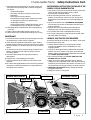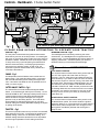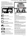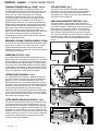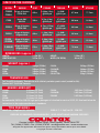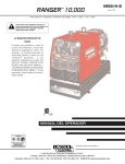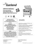
1
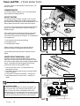
®
Britain’s Best Selling Range of Garden Tractors
C SERIES
Garden Tractor
OWNERS HANDBOOK
CERTIFICATE OF CONFORMITY
E.C Declaration of Conformity
I, the undersigned A.Bennett of Countax Limited, Great Haseley, Oxford England certify that
the lawnmowers:
MODEL
C-550
C-300
C600
C800
C400
C-38H
9.7
Power (Kw)
13.4
9.25
11.9
11.2
12
Max Rotation of Blades (rpm)
3000
3000
3000
3000
3000
3000
Honda
B&S
Engine Manufacturer
B&S
B&S
B&S
B&S
Engine Type
Petrol
Petrol
Petrol
Petrol
Petrol
Petrol
192
192
Mass in Kg
192
192
192
192
Max Drawbar Pull (Kg)
400
400
400
400
400
400
at Coupling Hook
Max Vertical load (Kg)
25
25
25
25
25
25
100 Db(A) @ 3000rpm
100 Db(A) @ 2600rpm
Max Sound Power Lever
3.2
3.2
Vibration (m/s/s) hands:
3.2
3.2
3.2
3.2
4.2
4.2
4.2
4.2
4.2
4.2
Vibration (m/s/s) seat:
Type of Cutting Device
Cutterbar Cutterbar Cutterbar Cutterbar Cutterbar Cutterbar
76cm
76cm
76cm
76cm
76cm
76cm
Width of Cutting Device
Conforms to the specification of Directive 84/538/EEC (as adapted to the technical progress by
Directive 87/252/EEC and amended by Directive 88/180/EEC and Directive 89/392/EEC (amended
by 91/368/EEC, 93/44/EEC and 93/31/EEC) and Directive 89/336/EEC and amended by 91/263/EEC
92/31/EEC).
Standards used: BS5107, EN292, ISO3767, ISO3864
Tested at Oxford. England
I declare that on behalf of Countax Limited these machines conform to
EC Essential Health and Safety requirements.
Signed:
A. Bennett (Technical Director) 01/01/01
Name of Dealer:
Address of Dealer:
Tel:
Fax:
Email:
®
Britain’s Best Selling Range of Garden Tractors
Countax Limited, Countax House, Great Haseley Trading Estate
Great Haseley, Oxfordshire OX44 7PF
Tel: 01844 278800 • Fax: 01844 278792
www.countax.com • [email protected]
Safety Instructions & Information - C Series Garden Tractor
Safety Instructions
Controls - Dashboard
Controls - Indicators
Controls - Levers
Cutter Decks
Cutter Deck Removal
Cutter Deck Check List
Deck Levelling
Cutter - Drive Belt
Powered Grass Collector
Engine Check List
Engine Oil
Fuel
Air & Cooling
Battery & Spark Plug
Fuses & PCB
Wheels & Tyres
Tractor Wiring Diagram
HE Wiring Diagram
Page 1 & 2
Page 3
Page 4
Page 5
Page 6
Page 7
Page 8
Page 9 & 10
Page 11
Page 12 & 13
Page 14
Page 15
Page 16
Page 17
Page 18
Page 19
Page 20
-
YOU MUST FULLY READ THESE SAFETY INSTRUCTIONS
INCLUDED IN THIS MANUAL BEFORE ATTEMPTING TO OPERATE THIS
GARDEN TRACTOR. WE WILL ACCEPT NO RESPONSIBILITY FOR LOSS OR
DAMAGE RESULTING FROM THE IMPROPER USE OF THIS MACHINE.
CARELESS OR IMPROPER USE MAY CAUSE SERIOUS OR EVEN
FATAL INJURY.
Mandatory Safety Instructions For The Use of
Countax Tractors
TRAINING
1. Read the instructions carefully. Be familiar with controls
and the use of equipment.
2. Never allow children or people unfamiliar with these
instructions to operate the mower.
3. Never mow while people, especially children or pets are
nearby.
4. The operator or user is responsible for accidents or
hazards occurring to other people or their property.
5. Do not carry passengers.
6. All drivers, should seek to obtain professional and
practical instruction. Such instruction should include:
• The need for care and concentration when
working with this machine.
• Control of a tractor sliding on a slope will not be
regained by the application of the brake.
• The main reasons for loss of control are:
i) Insufficient wheel grip
ii) Driving too fast
iii) Inadequate braking
iv) Incorrect load distribution
PREPARATION
1. Check that the machine complies with all applicable
regulations, including those in force when used on the
public highway.
2. When mowing, always wear substantial footware and
long trousers. Do not operate when barefoot or with
sandals.
3. Thoroughly inspect the area where the tractor is to be
used and remove all stones, sticks, wires and bones or
any other foreign objects.
-
P a g e
1
-
4. WARNING – petrol is highly flammable:
• Store fuel in containers specifically designed for
this purpose.
• Refuel outdoors only and do not smoke while
refuelling.
• Add fuel before starting the engine. Never remove
the cap from the fuel tank or add petrol while the
engine is running or when engine is hot.
• If petrol is spilled, do not attempt to start the
engine but move the machine away from the area
of spillage and avoid creating any source of
ignition until petrol vapours have dissipated.
• Replace the fuel tank securely.
5. Replace faulty silencers.
6. Before using, always inspect to see that the blades,
bolts and cutter assembly are not worn or damaged.
7. Check the condition of the tyres and ensure that they are
inflated to the correct pressures (refer to the
specifications). This is particularly important if the
machine is to be taken on the public highway.
8. Check that the mower is in good working order paying
particular attention to brakes and steering.
9. Check that all linkages, connections and pivot nuts are
secure and that the wheel nuts are torqued correctly.
OPERATION
1. Do not operate the engine in a confined space where
dangerous fumes can collect.
2. Mow only in daylight or in very good artificial light.
3. Before starting the engine, disengage blade and
attachment drives and shift into neutral.
4. Take care on slopes of more than 10º.
5. Remember, there is no such thing as a ‘safe slope’.
Travel on grass slopes requires particular care to guard
against overturning:
• Do not stop or start suddenly when going up or
downhill.
• Engage drive slowly. Always keep the machine in
drive when travelling up or down a slope.
• Machine speed should be kept low on slopes and
in tight turns.
• Stay alert for humps and hollows and other hidden
hazards.
• Avoid mowing across the face of the slope.
6. Watch out for traffic and stop blades rotating when
crossing or near roadways.
7. When using the machine, never direct discharge or
material towards bystanders or allow anyone near the
machine while in operation.
8. Never operate the mower with defective guards, shields
or without safety protective devices in place and in good
working order.
9. Do not change governor settings to increase the revs of
the engine. Operating an engine at excessive speed
increases the hazard of injury.
10. Before leaving the operators position:
• Disengage the drive to the cutter blades and
attachments, and lower the attachments.
• Apply the Parking Brake (change into neutral first
– on C300M).
• Stop the engine and remove the ignition key.
C Series Garden Tractor - Safety Instructions Cont.
11. Disengage drive to attachments, stop the engine and
disconnect the spark plug lead or remove the ignition
key before:
• Cleaning blockages.
• Checking, cleaning or working on the mower.
• Refuelling.
• Removing the Grass Collector.
• After striking a foreign object (inspect the mower
for damage and make any repairs before
restarting the tractor).
• If the machine starts to vibrate abnormally, check
immediately and call your dealer if necessary.
12. Disengage drive to attachments when transporting or
not in use.
13. Reduce the throttle setting during engine run-out.
14. Never work on the mower when the engine is running.
SUPPLEMENTARY INSTRUCTIONS FOR THE USE OF THE
COUNTAX C SERIES GARDEN TRACTOR
1. Use good common sense at all times, and to ensure this
tractor is safe and serviceable, fit only original
manufacturer’s supplied spares.
2. When inspecting the area to be cut, note also the
position of any stumps, manhole covers, bumps and
depressions and avoid them to prevent damaging the
blades.
3. We recommend the use of STANDARD UNLEADED
fuel and that you ensure the fuel tank is full before you
start the machine.
4. Always disconnect both battery terminals before
attempting any work in the engine compartment.
5. Do not leave the tractor unattended and running.
6. Do not put hands near moving belts of the Power TakeOff pulley while it is rotating.
MAINTENANCE
1. Check that all nuts, bolts and screws are tight to be sure
the equipment is in safe working condition.
2. Never store the equipment with petrol in tank inside a
building where fumes may reach an open flame or spark.
3. Allow the engine to cool before storing it in any enclosed
space.
4. To reduce the risk of fire, keep the engine, silencer and
battery compartment free of grass, leaves, petrol or
excessive grease.
5. Check the Grass Collector frequently for wear or
deterioration.
6. Replace worn or damaged parts for safety.
7. If the fuel tank has to be drained, this should be done
outdoors.
8. Be careful during adjustments of the machine to prevent
entrapment of the fingers between moving blades and
fixed parts of the machine.
Powered Grass Collector
Lift Lever
LAYING UP YOUR TRACTOR FOR THE WINTER
Your tractor should be serviced by your dealer – book early
to beat the last minute rush.
1. Ensure that the last fill of your petrol tank includes
Countax fuel additive which is available from your
supplying dealer.
2. Having run the engine with the additive enhanced fuel
either in use or for at least 15 minutes, disconnect the
battery, making sure the terminal leads are removed and
then DRAIN THE FUEL TANK.
3. Re-connect the battery and START AND RUN THE
ENGINE UNTIL IT STOPS.
4. Wash your tractor, taking particular care to clean all
cuttings from the underside of the Cutter Deck and keep
water away from electrical components. Countax do not
recommend the use of high pressure or steam cleaners.
5. REMOVE THE BATTERY and/or charge periodically
throughout the winter.
6. Keep your tractor in a dry place.
Control Levers
Dashboard Controls
Tipping Lever
Sweeper Height Adjustment
Cutter Deck
Foot Controls
-
P a g e
2
-
Controls - Dashboard - C Series Garden Tractor
O
O
Headlight Switch
Choke
Ignition
Cutter Switch
Aux. Lift Switch
Deck Lift Switch
Throttle
The console on your tractor may look different from that illustrated
Fig 1
PLEASE READ BEFORE ATTEMPTING TO OPERATE YOUR TRACTOR
IGNITION - Fig 1
HEADLIGHT SWITCH - Fig 1
The ‘Key Start’ controls both the ignition and the starter.
Insert the key and turn to the first position – the dash lights
will come on (check all is ready to start), then turn further to
activate the starter. Release as soon as the engine starts.
To stop, turn the key to the left (having first switched off
both the Cutter and PTO). It is always good practice to
remove the key and keep it safe. As with a car, it is
important to prevent unauthorised use by children who
could injure themselves.
The headlights are turned ON by switching the rocker
switch down. The Headlights will not operate when the
ignition is OFF. Turn the Headlights OFF before starting or
stopping. Remember – DO NOT operate your tractor in
darkness unless you have adequate artificial light.
CHOKE - Fig 1
An independent choke is fitted to some models in the C
Series range. This choke should be used in conjunction
with a fast throttle setting when starting the engine from
cold. It should be cancelled as soon as possible and not
used on a warm engine.
CUTTER ON/OFF SWITCH - Fig 1
The Cutter Switch controls the Electromagnetic Blade
Clutch. It works like a light switch (but in reverse) – UP for
ON and DOWN for OFF. Although it always returns to the
central position and the Cutter Deck will automatically
switch off when the engine is stopped, it is not good
practice to rely on this safety feature. The Cutter Deck
should always be switched OFF as soon as you have
finished cutting and certainly BEFORE stopping the engine
or getting off the tractor.
THROTTLE - Fig 1
This lever is pushed forward and up for FAST and CHOKE,
back and down for SLOW. A cold engine is started on the
CHOKE setting, a warm one on the FAST setting. The
CHOKE setting should be cancelled as soon as possible
and the engine operated on FAST setting at all times.
-
P a g e
3
-
:
es
Not
Please Note: - SAFETY SWITCHES
SEAT SAFETY SWITCH:
Your Countax tractor is fitted with a safety switch that will
turn OFF the engine and Cutter Deck should you
dismount. This is a safety device and SHOULD NOT be
used voluntarily. If you want to dismount from the tractor
and want the engine to continue running, first switch OFF
the Cutter Deck, then apply the Parking Brake. You can
now dismount. DO NOT LEAVE THE ENGINE IDLING
FOR ANY LENGTH OF TIME. Should you dismount with
the Parking Brake ON, the Cutter Deck will cut out after a
short delay of a couple of seconds. Do not rely on this
back-up cut-out. Ensure your safety by switching the
Cutter Deck off.
BRAKE PEDAL SAFETY SWITCH:
Your Countax tractor is fitted with a safety switch under
the Brake/Clutch pedal. This switch earths the ignition
unless the brake is on. The engine will only start while the
Brake/Clutch pedal is depressed. Two red lights on the
dash (Ignition and Brake) indicate that the Engine is
ready to start
C Series Garden Tractor - Controls - Indicators
CONTROLS - FORWARDS & REVERSE (Except C300M)
DASHBOARD INDICATORS - Fig 2
In the centre of the dashboard console on your tractor
will be a display panel. Figure 2 illustrates the panel of
a C Series HE model, some models may differ in the
appearance of the indicator layout - but each symbol is
described below. It is important that you get to know what
each symbol means, spend some time studying the
diagrams below.
Dashboard Indicators
Pedal B
Pedal A
P
Fig 2
‘Cutter On’ Symbol
This light flashes continuously when the Cutter is running.
‘Ignition On’ Symbol
This indicator goes out when the Cutter is running.
P
P ‘Charge’ Symbol
This indicator comes on only when the battery is charged
P
(if this indicator is not lit by the end of the mowing session
you should run the engine at maximum revs until it lights or
remove the battery for charging).
P
‘Brake - On’ Symbol
This indicator illuminates when the Parking Brake is
engaged.
P
P
‘Deck Height’ Indicator
This illuminated display illustrates the height of the cut that
the Cutter Deck is currently working at.
‘Hour Meter’ Indicator
This meter displays the number of hours the tractor has
been running since it was built (very much like a odometer
on your car). Use it in the same way for judging services
and oil changes.
Fig 3a
PEDAL A PEDAL B PEDAL C -
Pedal C
Emergency Brake and Parking Brake
Forward Speed control
Reversing control
MOVING OFF - Fig 3a
To move off, ensure your feet are off pedals ‘B’ and ‘C’,
then release the Parking Brake by depressing and
releasing pedal ‘A’. Now gently depress pedal ‘B’ and you
will move off. The further you depress pedal ‘B’, the faster
you will go. Its function is very similar to that of the
accelerator on an automatic transmission car, except that it
controls the hydrostatic drive and not the speed of the
engine.
REVERSING - Fig 3a
To engage and control reversing, simply take your foot off
pedal ‘B’ – to avoid a rapid stop, remove your foot gently.
The tractor will come to a standstill. When the tractor is
stationary, press pedal ‘C’ to move backwards.
EMERGENCY BRAKING - Fig 3a
In normal use, removing your foot from either of the drive
pedals is all that is required to stop the tractor safely and
quickly. For an emergency stop, press pedal ‘A’ whilst
releasing the drive pedal, this will add physical braking to
the normal hydrostatic braking.
PARKING - Fig 3a & Fig 4
Remove your foot from pedals ‘B’ and ‘C’ and the tractor
will come to a standstill. Now depress pedal ‘A’; keeping
pedal ‘A’ depressed, firmly press down on the Parking
Brake knob ‘D’ (Page 5, fig 4) using your left hand. Whilst
keeping knob ‘D’ depressed release the Brake/Clutch
pedal ‘A’ and it should remain in the engaged depressed
position. Now gently release the Parking Brake knob, and
your tractor will now be parked. When you turn off the
engine, the natural braking of the hydrostatic system will
add to the effect of the brake, its like leaving your car in
gear! To release Parking Brake simply depress pedal ‘A’.
-
P a g e
4
-
Controls - Levers - C Series Garden Tractor
TRANSAXLE TRANSMISSION (e.g. C300M) - Fig 3b
SEAT ADJUSTMENT - Fig 5
If your tractor is fitted with a manual transmission, the
forward speeds and reverse are controlled manually via a
control lever to the right of the driver. The tractor can be
driven off in any of the forward gears, each number
representing a speed that the tractor can travel at (e.g.
1=SLOW, 6=FAST). The machine must always be at a
standstill before you can change the lever setting to a
different speed. The tractor is stopped by depressing the
Brake/Clutch pedal situated on the right hand side of the
central console. Keeping this pedal depressed, move the
Gear Select Lever to the required gear then SLOWLY
release the pedal to engage drive to the wheels of your
tractor. To park, depress the Brake/Clutch pedal, then push
and hold down the Parking Brake (D). Release the
footpedal and you will be parked. Depress the footpedal
again to release the brake.
The seat on the C Series is adjustable forwards and
backwards to suit the operator. Simply lift the seat latch
at the front or the seat and slide the seat forwards or
backwards to suit. Always ensure the seat is latched back
into position before driving off.
To achieve this, depress the Brake/Clutch pedal fully whilst
the tractor is in motion, the machine will come to a sharp
sudden standstill. Remember, this procedure should
NEVER be used during normal use – misuse of this feature
could damage your tractor.
The natural braking of hydrostatic means that it is not
possible to push or freewheel the C Series tractor with the
hydrostatic engaged. To disengage, first make certain that
the machine is on a flat even surface, then release the
parking brake by depressing pedal ‘A’. Locate the Dump
Valve, situated along side the rear right wheel and pull it
out. You will now be able to push the tractor at a speed not
exceeding 2mph. Make sure you disengage the Dump
Valve by pushing the lever back BEFORE starting your
tractor.
Speed Control Lever
5
4
3
2
1
N
EMERGENCY BRAKING (TRANSAXLE MODELS: C300M)
DUMP VALVE (HYDROSTATIC TRACTORS) - Fig 6
POWER TAKE-OFF (PTO) - Fig 4
6
The PTO delivers power from the tractors engine to any
driven attachment connected to your tractor (e.g. Powered
Grass Collector). The PTO lever is situated to the right of
the driver beneath the seating position. To engage, lift the
lever to the LEFT and DOWN, letting it find its own height.
To disengage, pull the lever UP and to the RIGHT. Always
have this lever in the disengaged position when not in use.
Do not put hands near moving pulleys and belts.
Fig 3b
PTO Engage Lever
CUTTING HEIGHT (HE MODELS) - Fig 1
The cutting height of your tractor is adjusted by pressing
the rocker switch on the right hand side of the dashboard
(page 3, fig 1), UP for higher or DOWN for lower. The
illuminates indicator on the centre display panel indicates
the position of the Cutter Deck. Ten illuminated heights are
marked for guidance purposes only – the cutting height is
in fact infinitely adjustable! To get the best from this
refinement, use it to continuously adjust the cutting height
to suit the ground and grass conditions. To avoid scalping,
do not make downward adjustments on the move until you
are familiar with the height control.
Parking Brake (D)
Cutter Height Lever
Fig 4
Seat Adjustment Lever
CUTTER HEIGHT LEVER (NON HE MODELS) - Fig 4
This lever is used to select cutting height. Down for LOW,
up for HIGH (from about 13mm to about 90mm). The 10
cutting heights are numbered in relation to the height that
the Deck cuts at. We suggest you select position 3 of 4 for
mowing lawns and position 8 or 9 for very long grass and
paddocks. In practice you will discover the height you need
for each area of your grounds. In wet or heavy conditions it
is advisable to select a higher position than you would
normally in light or dry conditions.
Fig 5
Dump Valve Position
Fig 6
-
P a g e
5
-
C Series Garden Tractor - Cutter Decks
MULCH MOWING - Fig 7
Mulching can save time, avoids gathering piles of rotting
cuttings and feeds your lawn. It is however necessary to
observe certain rules to mulch mow successfully.
• Reduce the height of the grass by no more than 1/3rd its
height in each pass. If the grass has grown long, make
several passes to achieve the cut height you require.
• Always cut with the throttle set to FAST – mulching
needs the full running speed of your tractors engine.
• Mow often, particularly in spring and early summer.
Short clippings of 25mm (1") or less decompose more
quickly.
• If possible avoid cutting in the wet.
• If an unsightly residue of cuttings is being left –
increase the cutting height.
Mulch Cutter Arrangement
Fig 7
• Always keep the underside of the Cutting Deck clean to
ensure good grass flow.
• Always check that the blades are sharp and kept in good
condition – but do not attempt to sharpen or replace the
blades yourself – Countax blades are not expensive and
it is good practice to ask your dealer to change them
regularly.
:
es
Not
Please Note: - MULCHING
HOW MULCHING WORKS:
The Countax Mulcher Cutting Deck has three mulching
compartments. The grass cuttings are lifted and held until
they are cut several times and injected back into the turf
as small particles. These release nutrients back into the
soil.
Mulch Pulley Arrangement
PULLEY ARRANGEMENTS - Fig 8 & 9
Fig 8
Figures 8 and 9 illustrate the pulley arrangement and belt
run of the C Series Mulcher Deck and IBS Deck (refer to
decal on Cutter Deck for replacement belts and blades).
These diagrams are for guidance purposes only and
Countax recommends that the replacement of Cutter Deck
drive belts be carried out by your local Countax Dealer.
Mulching Process Illustration
Fig 9
IBS Pulley Arrangement
-
P a g e
6
-
Cutter Deck Removal - C Series Garden Tractor
The Rear Discharge Deck is used in conjunction with the
PGC. It ejects grass rearwards after cutting for the
Powered Grass Collector to collect. Either the Mulch Deck
or the Rear Discharge Deck can be fitted to the C Series
using the following instructions.
C
B
A
F
REMOVAL OF CUTTER DECK - Fig 10
The Cutter Deck can be quickly removed for servicing or
cleaning or to give greater clearance when driving or
towing over uneven ground. Follow this sequence:
1. Put the Cutter to its lowest position (see page 5).
2. De-tension the Cutter Drive Belt with the Deck Tension
Lever situated under the left (nearside) running board
(see figure 13).
3. Remove the 3 securing pins from the front of the deck
(fig 11 – A, B and C) by pulling out the spring clips.
4. Remove the 2 securing pins and washers from the back
of the deck (fig 12 – D and E).
5. Slip the Cutter Deck Drive Belt off the Engine Pulley.
6. Slide the Deck out.
7. If you are going to use the Tractor without the deck,
remove the Securing Bar (fig 10 – F).
8. Reverse this procedure to re-install.
:
es
Not
E
Fig 10
C
Please Note: - CUTTER DECK REMOVAL
IMPORTANT
When replacing the Cutter Deck, Re-tension the belt with
the lever under the running board BEFORE attempting to
use your tractor.
B
A
Fig 11
TO CLEAN THE CUTTER DECK
Remove the deck as instructed, stand it on its side and
hose off accumulated cuttings. This may be necessary
routinely to prevent build up of cuttings, particularly at the
beginning of the season when the grass is lush and wet.
Thoroughly wash the underside of the Cutter Deck as
regularly as possible.
D
ENGINE TO CUTTER DRIVE BELT REPLACEMENT
To replace the Engine to Cutter Drive Belt, follow this
sequence:
1. Pull the Belt Tension Lever forward to detension (fig 13).
2. Lower the Cutter Deck to the lowest position (page 5).
3. Remove the belt from the Forward Electric Clutch Pulley
– it will slip off.
4. Remove the Cover of the Cutter Deck Pulley Housing –
loosen and remove the 1/4" UNF nut and bolt using two
7/16" spanner/sockets – then slide (tap) the cover off.
5. Remove the belt from the Cutter Deck Pulley – you may
have to ease it off by rotating the pulley.
6.Now replace the CORRECT BELT (see decal mounted
on Cutter Deck), by reversing this procedure, taking care
to fit the belt into the ‘V’ grooves.
7. Pull back the Belt Tension Lever so the Belt is tensioned.
Now check and adjust belt tension as detailed on
page 11.
Fig 12
De-tensioned
Belt Tension Lever
Fig 13
-
P a g e
7
-
E
Tensioned
C Series Garden Tractor - Cutter Deck Check List
CUTTER FAILS TO START OR CUTS OUT WHEN
SWITCHED ON
Check:
• Are you on the tractor? – Unless you sit on the seat, the
safety switch cuts out the Cutter Deck.
• Is the battery low? – The Clutch Engage Switch will only
operate if the battery is well charged.
• Does the 10Amp-barrel fuse on the printed circuit board
need replacing (see page 19, fig 57).
• That either the Cutter Switch or the Safety Switch on the
seat is not faulty – if so, call your dealer.
UNEVEN CUT (CUTS SHORTER ONE SIDE THAN
THE OTHER) - Fig 14
Check:
• That the tyres are all inflated to the correct pressures
(see back sheet).
• That the front axle is pivoting freely.
• That the deck suspension brackets are moving freely
and not hitching up.
• That the side deck level adjustment is correct (page 10).
Fig 14
Cutter Not Level Side to Side
Cutter Not Level Front to Back (Tipped Forward)
CUT IS UNEVEN OR UNTIDY IN ONE OR MORE SECTORS
Check:
• That the Cutter Deck is levelled correctly front to back
(page 9).
• That one or more of the blades are not worn or
damaged – if so, call your dealer.
THE CUTTER SEEMS TO LOSE POWER AND THE BELT
SLIPS AND OVERHEATS
Check:
• That the Tensioner Rod is correctly applied.
• That the Cutter Belt Tension is correct (see page 11).
• That the Cutter Deck is not clogged with wet cuttings.
• That the Cutter Drive belt is not worn.
Fig 15
Cutter Not Level Front to Back (Tipped Back)
We do not recommend that customers attempt to change
cutting blades themselves, remember that it is never
worthwhile to have blades reground. It is cheaper and
better to replace blades – re-grinding is likely to affect the
hardening of the blade and its balance.
Fig 16
Individual Cutter Blades Damaged or Bent
:
es
Not
Please Note: - BEFORE YOU START
IMPORTANT
The information contained on this, and the following
pages is given on the understanding that Countax
accepts no responsibility for work carried out by a
customer or for any damage thus caused, whether or not
the service instructions have been misunderstood. To be
sure that your warranty terms are not breached, service
work should only be carried out by your dealer.
Bent blade
Fig 17
-
P a g e
8
-
Deck Levelling - C Series Garden Tractor
The Cutter Deck should be set so that it is parallel to the
surface it is cutting with a maximum variation from side to
side, or front to back of 3mm. Check this by placing the
tractor on a hard level surface and measuring the
clearance heights front to back and side to side with a steel
ruler or tape with the Cutter set one adjustment up from its
lowest position.
If the Cutter Deck seems to require levelling, first
check these other possible causes:
1. Are the tyres correctly inflated? – If not, rectify using the
figures on the back page as a reference.
2. Are the Cutter Deck Hanger brackets (fig 19) moving
freely or are they hitching up. To check this, lift the Cutter
deck to its highest position and lift and rock it, watching
to ensure that the brackets move freely – if not, clean
and grease.
3. Is the front axle pivoting freely? – If not, clean and oil.
4. Is there any impact damage that has bent or distorted
the Deck or Suspension Brackets (a matter for your
dealer)?
Fig 18
Front to Back Adjustment Rod
If the Deck is still uneven then:
LEVELLING FRONT TO BACK - Fig 18, 19 & 20
You need two people for this operation – one to lift the
Deck while the other removes or relocates the Trunnion.
1. Ensure that the Anti-Scalp Wheels are all set to the
same height – if not, rectify (fig 20).
2. Lower the Cutter Deck to a position one above the
lowest setting – check levels with a ruler or tape at a
position close to the front and rear anti-scalp wheels.
3. Now locate the Front to Back Adjustment Rod to the right
near offside wheel, you will find the Trunnion (fig 19) that
links the rod to the Deck Hanger Bracket. Both the
Trunnion and the Rod are threaded and adjustment is
achieved by rotating the Trunnion to ‘in-effect’ lengthen
the Rod.
4. To free the Trunnion, use a 9/16" spanner or socket to
remove the 3/8" Nyloc nut and washer and push it free.
5. Locate a block of wood underneath the front of the
Cutter Deck to offer support.
6. Rotate the Trunnion to advance it up the Rod to lift the
back of the Deck. Rotate it the other way to lift the front.
Adjustment is rapid, so try one or two turns first and
relocate the Trunnion Bracket and secure – then check
the effect. Repeat and re-check if necessary.
:
es
Not
Trunnion
Fig 19
Anti-Scalp Wheels
Adjustment Holes
Please Note: - BEFORE YOU START
IMPORTANT
The information contained on this, and the following
pages is given on the understanding that Countax
accepts no responsibility for work carried out by a
customer or for any damage thus caused, whether or not
the service instructions have been misunderstood. To be
sure that your warranty terms are not breached, service
work should only be carried out by your dealer.
-
Deck Hanger Bracket
P a g e
9
-
Fig 20
C Series Garden Tractor - Deck Levelling
LEVELLING SIDE TO SIDE
Deck Level Disk
Adjustment is best done with the Deck in a position one up
from its lowest cut – check the level both sides and
levelling is then achieved by adjusting the left (nearside) of
the deck at two points.
REAR ADJUSTMENT - Fig 21 & 22
1. Find the Deck Level Disk (fig 21) near the back
(nearside) wheel. This has a concentric slot in which the
Deck Levelling Rod is located.
2. Using a 1/2" spanner, loosen the 5/16" Nyloc nut (fig 22)
(A) securing this stud just enough to permit some
movement.
3. Now lift or depress the Deck depending on the
adjustment you wish to achieve. This will move the stud
up or down the disk (B) – the higher up and nearer the
centre of the disk the higher the deck.
4. Check with your ruler or tape and having levelled the
Deck at the rear, re-tighten the Nyloc nut.
Deck Adjustment Plate
Fig 21
FRONT ADJUSTMENT - Fig 21 & 23
1. Having levelled the rear of the Deck, check if the front is
level. If not, you will need to find the Deck Adjustment
Plate (fig 23) which is forward of the Cutter Deck near
the front (nearside) wheel.
2. Before making adjustments, loosen the two sets of nuts
and bolts (C & D) securing the Deck Levelling Bracket
(E) using a 13mm spanner and 13mm socket.
3. Then, using a 13mm spanner, loosen (upper)
locknut (F).
4. Now adjust the height by using a ratchet or spanner to
turn the Nyloc nut (G) clockwise (up) to raise the Deck or
anti-clockwise (down) to lower it.
5. When correct level is achieved, tighten up all nuts and
bolts except G.
ANTI-SCALP WHEELS - Fig 20
A
B
Deck Level Disk
Fig 22
For the closest cut, set the Anti-Scalp Wheels (Page 9, fig
20) in the middle adjustment holes. If you are experiencing
scalping, this can be minimised by setting the wheels in the
lowest adjustment holes.
F
:
es
Not
Please Note: - BEFORE YOU START
C
IMPORTANT
The information contained on this, and the following
pages is given on the understanding that Countax
accepts no responsibility for work carried out by a
customer or for any damage thus caused, whether or not
the service instructions have been misunderstood. To be
sure that your warranty terms are not breached, service
work should only be carried out by your dealer.
G
D
Fig 23
E
Deck Adjustment Plate
-
P a g e
1 0
-
Cutter - Drive Belt - C Series Garden Tractor
Before carrying out tests or adjustments (the problem
maybe simpler) – first check the following points:
1. Is the Engine to Cutter Drive Belt slipping? Check that
the Drive Belt Tension Lever (fig 13) under the left
running board is in the tensioned position. If not, rectify –
this is the most likely cause of Cutter failure.
2. Has debris collected in the Cutter Deck Pulley Housing?
If so, remove the cover and remove the obstruction.
Access from here:
ENGINE TO CUTTER DRIVE BELT TENSION
The correct tension of the Cutter Drive Belt (Engine to
Deck) is critical. If incorrectly set it can lead to engine
damage.
To check the tension, follow procedure:
1. Put the deck in a middle cutting height position (5 on the
HE illuminated indicator).
2. Select a midway position on the Belt between the front
(Electric Clutch) pulley and rear (Cutter Deck) pulley and
using a spring balance; apply a 2Kg (4-5lbs) pull (fig 26).
3. Using a ruler or tape, measure the deflection achieved
which must be 13mm (1/2"). If more, the belt tension
must be increased, if less – decreased.
To correct the tension, follow this procedure:
1. Release the tension on the belt by pulling the Belt
Tension Lever (page 7, fig 13) forward.
2. Taking care not to burn yourself on a hot exhaust, locate
the Trunnion at the end of the Belt Tension Rod, look to
the front (nearside) close to the exhaust (see fig 24).
3. Remove the Spring Clip and washer holding the
Trunnion in place on the Deck Tension Cradle (fig 25)
and release the Trunnion so it can be turned.
4. Both the Trunnion and the Belt Tension Rod are
threaded. You increase belt tension by winding the
Trunnion towards the end of the Rod and reduce tension
by winding in the reverse direction.
5. Having made the adjustment, re-locate and secure the
Trunnion, re-tension the Belt with the Belt Tension Lever
– then re-check the Belt tension.
Fig 24
Spring Clip
Deck Tension Cradle
Deck Tension Rod
Washer
Trunnion
Fig 25
Deck Tension Cradle
Kg
:
es
Not
Please Note: - WARNING
IMPORTANT
On NO account must the tractor be run with the Engine to
Cutter Drive Belt over-tensioned as it will damage the
Engine. As any such damage will not be covered by
warranty, Countax strongly suggest you get your local
supplying dealer to set Tensions.
cm 13mm
Fig 26
-
2kg (4 - 5lbs)
P a g e
1 1
-
(1/2")
Checking Tension
C Series Garden Tractor - Powered Grass Collector
CONNECTING PGC TO TRACTOR - Fig 28
Position X
To connect the Powered Grass Collector (PGC) to your
C Series tractor, ensure that both are on an even surface
with the Locking Levers on the Collector facing the Lift
Arms on the tractor. Move the Collector manually to the
tractor, lower the lift arms using the Lever (fig 30) or switch
on dashboard (fig 1). Then lift/tip the seat forward and lift
the PTO flap to expose the PTO pulley.
At the end of each Lift Arm, you will find a Locating Lug.
Slide the channels on either side of the Powered Collector
over the Lugs, but do not engage the Locating Lever yet.
Ensure that the Rubber Flap at the opening of the PGC is
located on the top of the Transmission Grass Deflector.
INSTALLING THE DRIVE BELT - Fig 29
Place the Drive Belt over the PTO pulley (beneath Tractor
Seat). Standing adjacent to the Tractor, extend the belt with
both hands parallel to the ground. Now twist the belt to
form a figure ‘8’ - the right hand up and the left hand down.
In this position place the other end of the belt over the
Powered Collector Pulley. Be sure that this is installed the
right way round, otherwise the brush will work in reverse
and collection will be poor. Lock the Locating Lever over
the Lift Arm Lugs. Rotate the Locking Clips over the Lift
Arm Lugs. To disconnect, reverse this procedure.
FITTING THE NET - Fig 27
Fit the Net as shown in fig 27 with the net rod (A) in position
‘X’. To remove the net, release the net rod (A) and secure
in the removal position ‘Y’.
PTO DRIVE BELT TENSION - Fig 29
Engaging the Locating Lever tensions the belt which
should not be run too tight - to check the tension there
should be a 19mm deflection with light finger pressure
(2kgs) at a midway point between PTO pulley and
Sweeper Pulley. It is important after attaching the Sweeper
to the Tractor to check the Belt Tension and adjust if
necessary. This must be done before the Sweeper is put
into operation and with the Sweeper on the ground. With
light finger pressure (2kgs, 4-5lbs), there should be a total
deflection of 19mm (3/4”) at a midway point between PTO
Pulley and the Sweeper Pulley. If a Spring Balance is
available, a pressure of 2kgs (4-5lbs) is required for a
deflection of 19mm (3/4”). If the Belt Tension is incorrect, it
can be adjusted by movement of the Sweeper Locking
Levers or the threaded rod. Ensure the lock nuts are
suitably tightened after adjustment. Do not over-tighten the
lock nuts, as levers need to pivot.
Always be sure to keep the PTO lever in the disengaged
position and the Sweeper Lowering Lever in the transport
position when not collecting grass clippings.
Position Y
A
Net Fitting
Fig 27
Locating Lug
Locking Clips
Locating Lever
Lift Arm
Fig 28
PGC Drive Pulley
19mm Deflection
@2Kgs Push or Pull
Tractor PTO
Fig 29
To Tighten
To Slacken
PGC Raising/Lowering Arm
Lowered Position
LOWERING THE COLLECTOR - Fig 30
Using the Lever (fig 30) or the Aux Lift switch (HE tractors
only) situated on the Console (page 3) lift or lower the
Powered Grass Collector.
Transport Position
Fig 30
-
P a g e
1 2
-
Powered Grass Collector - C Series Garden Tractor
If your Collector appears to be not picking up satisfactorily,
check the following:
1. The PTO lever is engaged.
2. That the PTO pulley beneath the seat is turning – if not,
call your dealer.
3. That the Collector Belt is not reversed (if it is correct, the
brush revolves against the forward direction of the
tractor (fig31)).
4. That the Brush Height Adjustment Lever is not set too
high or too low (fig 34).
5. That there is not a build up of congealed grass on the
leading edge of the Brush Guard.
6. That the Brush is not clogged.
7. That the Collector Belt is not slipping, if so then adjust
the tension or replace the worn or damaged belt.
8. That the Collector net is not clogged. If so, wash or
brush with a stiff hand brush.
9. That the Brush is not damaged.
Correct Brush Rotation
Fig 31
Tipping Lever
TIPPING CUTTINGS - Fig 32
When it is full, raise the Collector to the Transport position
(using the Lift Lever – page 12 or Lift Switch page 3), drive
to your tipping area, reverse to the pile, select neutral and
extend the Tipping Lever.
CHECKING, TENSIONING AND REPLACING SIDE
DRIVE BELT - Fig 33
Fig 32
1. First Remove Collector from the tractor.
2. To remove the plastic cover, remove the two nuts and
bolts (A) using a 1/2" spanner and socket.
3. Using a 1/2" spanner and socket, slacken the nut and
bolt (B) holding the tension pulley and slide the pulley out
of the way.
4. Remove the belt and fit the Countax replacement belt.
5. Tension the belt by sliding back and securing the belt
tensioner. The tension is not critical but the belt must not
be too tight. The ideal is 13mm (1/2") deflection at 2kgs
(4/5lbs) pull – use a spring balance and ruler or tape to
check.
6. Make sure that the rectangular cover plate fits over the
adjustment slot – failure to do this will allow cuttings and
grit to accumulate and damage the pulleys and belt
assembly.
7. Replace the plastic cover.
PGC Drive Belt Assembly
A
B
Fig 33
ADJUSTING THE SWEEPING HEIGHT - Fig 34
Using the Sweeper Height Lever, select a position
appropriate to the conditions and the height of cut. To get
the best sweeping performance and to preserve the
brushes, select the highest setting that works – start high
and adjust down until the brushes start to collect (normally
the middle adjustment hole). Do not set the brushes too
low – this will lead to scarifying and a very untidy finish as
well as shortening brush life.
Sweeping Height Lever
Collection Heights
Fig 34
-
P a g e
1 3
-
Tension Jockey
C Series Garden Tractor - Engine Checklist
STARTING AND RUNNING CHECK LIST
Before you start:
1. Check that the engine is filled with the correct oil
(SAE 30) and to the recommended mark – never over-fill
(fig 37).
2. Fill your Petrol tank with fresh unleaded premium petrol.
If it is more than 1/3rd full of old stale petrol that has
been in the tank 8 weeks or more – drain and then refill.
If less than 1/3rd full of old untreated fuel, completely fill
with new premium unleaded petrol. We recommend the
use of Countax Petrol Additive – it will keep petrol stored
in the tank in good order and it lubricates and protects
jets and valves.
3. Ensure the throttle is advanced to ‘FAST’, and if the
engine is cold that the choke is engaged.
4. Ensure that the Park Brake is ‘ON’ and that the
Brake/Clutch pedal is full depressed.
Oil Filler Cap location
Fig 35
Turn Oil Cap anti-clockwise
INSERT THE KEY AND TURN CLOCKWISE
If the dashboard ignition lights fail to come on – check:
1. That the battery terminals are connected (see page 18).
2. That the 15amp fuse is properly located and has not
blown (see page 19).
3. That the battery is charged.
If the engine fails to turn over – check:
1. That the brake is depressed or Parking Brake is on:
Fig 36
Check oil level
If the above do not apply – call your dealer.
If the engine misfires, loses power or stalls in use –
check:
1. That you have not run out of fuel.
2. That the air filter pre-cleaner is not blocked (page 17).
3. That the cooling air intakes are not blocked.
4. That the fuel filter is not blocked.
5. If the ignition lights have gone off – check the 15amp
fuse.
L
LL
L
U
FU F
L
L
FU
ltr .
25 x
0. plrtor . ltr
.
2p5 x 5
0a. ro .2 rox
0
p
p
ap
ap
If the engine turns over and does not start – check:
1. That the fuel tank is full and the Petrol Tap is turned ON
(page 16).
2. That the Spark Plug lead is connected.
3. That the outlet in the fuel tank is not blocked.
4. That the Spark Plug is clean and set to the correct gap
(page 18).
5. That the fuel filter is not blocked (see page 16).
D D
D AD
A
D
Fig 37
D
A
Top-up as required
:
es
Not
Please Note: - IMPORTANT
IMPORTANT
If there is evidence that the engine is overheating or if
you find the oil consumption to be high - call your dealer
without fail! Countax suggest that ALL service work to
your tractor and engine be carried out by your dealer.
Fig 38
-
P a g e
1 4
-
Engine Oil - C Series Garden Tractor
:
es
Not
Please Note: - OIL CHANGING
Oil DrainAdaptor
IMPORTANT
Oil should be changed without fail after the first eight
hours of running!
OIL DRAINING
The C Series tractor has an oil drain adaptor (fig 39)
located on the right hand (offside) of the engine. This is like
a bayonet light fitting, which you push in and turn anticlockwise to release. A short length of clear hose is
supplied in the toolkit that fits on this adaptor so that waste
oil can be poured into the can or bottle.
Fig 39
BEFORE DRAINING
1. Start the engine and allow to idle until warm (about five
minutes).
2. Switch off the engine, lift open the bonnet and unscrew
the oil cap/dipstick.
Oil Draining
TO DRAIN
1. Locate the Oil Drain (fig 39).
2. Remove the Yellow Dust Cap.
3. Fit the short length of hose supplied over the nozzle of
the adaptor (see fig 39) and direct the other end into a
container large enough to take 2-litres of waste oil.
4. Press the adaptor in; turn anti-clockwise and pull to start
flow (fig 40).
5. When the sump is empty, press in the adaptor and turn
clockwise to lock. Remove hose and store for next use.
Replace Yellow Dust Cap (fig 41).
6. Refill with recommended oil (SAE30 detergent oil
classified for service – SG, SF, SE) to engine
manufacturer’s instructions. DO NOT OVER-FILL. The
use of lubricants that are not recommended may lead to
excessive wear or damage – and this will NOT be
covered by warranty.
Fig 40
Oil Filter
Fig 42
-
P a g e
Fig 41
1 5
-
C Series Garden Tractor - Fuel
The fuel tank is situated under the bonnet beneath the
dashboard of your tractor (fig 43). Great care must be
exercised when dealing with petrol, so use common sense
at all times.
Fuel Tank Location
• Extinguish ALL naked flames and sources of ignition.
• Switch off the engine at the ignition and remove the key.
• If the tractor has been running, allow the engine to cool
before attempting to refuel.
• Refuel in a well-ventilated area, preferably outdoors.
• Keep fuel in a clean, purpose made container and make
sure that no water or other foreign substances can mix
with the petrol.
• Wear protective gloves.
• Always fill using a funnel with a mesh strainer.
FILLING THE TANK - Fig 43
1. Clean around the cap of the fuel tank before filling.
2. Fill with new unleaded petrol from a CLEAN container.
3. Use a clean funnel, preferably with a filter.
4. We recommend the use of Countax Fuel Additive,
particularly if the fuel is to be left for more than a couple
of weeks.
Fig 43
1/4 Turn - OPEN
1/4 Turn - CLOSED
FUEL FILTER - Fig 45 & 46
If you suspect that fuel is not getting through to the engine,
first check that the outlet in the fuel tank is not blocked.
Then remove the hose from the carburettor side of the ‘inline’ fuel filter (having first ensured that you have a
container into which fuel flow can be directed). If the fuel
flows, the filter is probably ok. If it is more than a year-old it
is sensible to replace it (consult your dealer).
Fig 44
Fuel Shut-Off Valve (where fitted)
If fuel is passing the in-line filter, it is likely that fuel is not
your problem. If the carburettor is the problem, it is only
serviceable by your dealer.
:
es
Not
Please Note: - BEFORE YOU START
IMPORTANT
The information contained on this, and the following
pages is given on the understanding that Countax
accepts no responsibility for work carried out by a
customer or for any damage thus caused, whether or not
the service instructions have been misunderstood. To be
sure that your warranty terms are not breached, service
work should only be carried out by your dealer.
Fig 45
Fig 46
In-line Filter on Single Cylinder
In-line Filter on Twin Cylinder
-
P a g e
1 6
-
Air & Cooling - C Series Garden Tractor
AIR INTAKE/COOLING SYSTEM
The cooling fan also supplies air to the carburettor so if the
engine won’t start or if it is stalling or overheating – check
the cooling fan system and the air filters.
1. Check that debris is not caught in the cooling fan cover –
clean with a stiff brush.
2. Remove the air-filter cartridges and check that debris is
not gathered on the Pre-Cleaner.
Single Cylinder Air Filter
Cover Knob
Air Intake
Cover
Cartridge Knob
After these checks you must consider whether the air filter
cartridges should be replaced.
Figures 47 & 48 illustrate the Briggs & Stratton air filters for
Single and Twin Cylinder engines. Great care is needed
when re-assembling them, make sure that all components
are replaced in the correct order and that they are secure.
If in any doubt, Countax recommends that you should
consult your dealer or the Countax Service Department for
advice.
Check with your engine manufacturer’s handbook for
service times of the air-filter pre-cleaner.
:
es
Not
Stud
Cartridge & Pre-Cleaner
Base
Fig 47
Twin Cylinder Air Filter
Please Note: - BEFORE YOU START
IMPORTANT
The information contained on this, and the following
pages is given on the understanding that Countax
accepts no responsibility for work carried out by a customer or for any damage thus caused, whether or not the
service instructions have been misunderstood. To be sure
that your warranty terms are not breached, service work
should only be carried out by your dealer.
Cartridge
Pre-Cleaner
Knob
Fig 48
Clean out chaff and dirt
Cover
Cooling Fan Cover
Air Vents
Fig 50
-
P a g e
Fig 49
1 7
-
C Series Garden Tractor - Battery & Spark Plug
BATTERY - Fig 51
Battery Terminals
The battery is located underneath the fuel tank of your
C Series tractor. As long as you follow these simple
maintenance procedures, the battery can last many years,
but always check with your dealer if you feel that the
battery is leaking or faulty.
As with a car, it is VERY important not to lay metal tools
across the terminals of the battery. Ensure that the terminal
connectors are tightly secured and not exposed to any
foreign metal objects loose in the battery compartment.
Regularly clean the terminals and coat with petroleum jelly
and ensure electrolyte levels are topped up to the correct
level, taking care not to over-fill.
Check that the battery terminals are correctly placed –
green neutral (-) red positive (+). The battery should be
periodically charged throughout the winter lay-off. It has
run down during normal summer use there could be
several causes.
Max charge rate: 1.5 amps
Fig 51
1. Distilled water not topped up.
2. Ignition left on.
3. 10amp fuse needs replacing.
4. The battery needs replacing.
If ‘1’, ‘2’ and ‘3’ appear not to be applicable, first re-charge
the battery using a trickle charger and await a second
failure before calling your dealer. Alternatively the engine
can be started using jump leads and the battery re-charged
in use.
SPARK PLUG - Fig 52
Please note the make of the engine used in your tractor
and be sure to fit the correct spark plug and set to the
correct gap.
See engine Manufacturer’s handbook for relevant spark
plug data.
Set Spark Plug to the Correct Gap
Fig 52
HEADLIGHTS - Fig 53
To replace a headlight bulb, follow this sequence:
1. Lift the bonnet and locate and unscrew bulb holder by
holding firmly and rotating in an anti-clockwise direction.
Be careful not to damage the reflector.
2. Remove the bulb from holder by carefully pushing it anticlockwise and then pulling to release.
3. To fit replacement bulb (12v 21w) push into holder and
rotate clockwise.
4. Insert bulb and bulb holder carefully into the headlight
and rotate clockwise until it locates.
Bulb (12v 21w)
Bulb Holder
NOTE: - If both lights have gone off, it could be the fuse on
the Printed Circuit Board (PCB) see page 19).
Headlight Reflector
Fig 53
-
P a g e
1 8
-
Fuses and PCB - C Series Garden Tractor
There are 2 fuses on the Standard C Series tractor, 3 on
the HE models.
Fuse Box Location
STANDARD TRACTOR
The 20amp (Yellow) charging circuit. The 15amp (Blue)
lights, ignition and safety switches.
HE SPEC TRACTORS
The left hand 20amp (Yellow) charging circuit. The mid
position 20amp (Yellow) lights, ignition, safety switches
(this replaces the 15amp fuse on the standard tractor). The
20amp (Blue) electric lift for Cutter Deck and Collector.
PCB Location
10
If the 15amp fuse blows when the ignition key is turned,
this means there is a short between the red and blue
coloured wire and the body of the tractor. The usual places
to investigate are:
10
To check – remove the fuses and check the small window
(fig 54 & 55), there should be an unbroken metal strip
bridging the gap.
Fig 54
1. The electrical PTO and socket (if fitted).
2. Seat Switch wires.
3. The Brake Micro Switch.
Please contact your dealer or the Countax Service
Department before investigating electrical shorts.
If fuses blow after these have been checked, call your
dealer.
Fuse Diagnosis
Fig 55
PRINTED CIRCUIT BOARD FUSES - Fig 57
There are 2 fuses on the Circuit Board, which can be
reached by removing the PCB cover (see fig 56). These
two fuses control the lights and the Electromagnetic Blade
Clutch. If the Blade Clutch disengages without being
switched off, these are the possible causes:
1. You have got off the seat – the safety switch will
disengage the Cutter.
2. The battery has lost charge and will no longer hold the
clutch in operation.
3. Fuse blown on Printed Circuit Board – see figure 57.
4. Faulty safety switch or break in wire – contact your
dealer.
PCB Casing
Fig 56
PCB Diagram
:
es
Not
Please Note: - BEFORE YOU START
ELECTRICAL WORK
Countax recommends that any electrical problems you
may encounter with your tractor by dealt with by your
dealer. If owners choose to undertake service work
themselves they do so at their own risk. Countax accepts
NO responsibility for any damage thus caused whether or
not the service instructions have been misunderstood.
Hour
Meter
(Located on
the other
side of the
P.C.B.)
Deck Height
Indicator
(Located on
the other side
of P.C.B.)
10Amp Cartridge Fuse for Lights
Fig 57
-
P a g e
1 9
-
10Amp Cartridge Fuse for Electric Clutch
C Series Garden Tractor - Wheels and Tyres
TYRES AND WHEELS
Countax Tractors are fitted with grassland tyres that are
designed to present a large area to the ground for grip and
are of soft profile to prevent marking your turf. They are of
thicker section and tougher than most 4 ply tyres.
Persistent punctures and tyre deflation are nevertheless a
problem experienced by around 5% of Countax customers.
This is not a problem just for Countax owners – it is shared
by the users of all types of off-road machinery fitted with
pneumatic tyres. In practically every case there is a
common cause – THORNS! Blackthorn, Hawthorn and
Rose are usually at the bottom of the problem and will
puncture any tyre not fitted with very expensive guards.
5. Using a flat ended screwdriver, lever off the ‘E’ clip and
remove the washers (fig 60).
6. Pull off the wheel carefully taking care not to dislodge the
tractor from the jack.
7. Remove the key from the wheel hub, first removing the
grease seal from the front of the hub using a small
screwdriver (keep safe with the key, ‘E’ clip and
washers).
When the tyre is repaired, fit the wheel onto the shaft; line
up keyways and tap in the key. Pull the wheel forward off
the shaft until the grease seal recess is just clear and refit
the seal. Then slide the wheel fully on the shaft. Reverse
instructions 1-6 to complete the job.
There are less expensive ways to overcome this problem so check and avoid these possible causes:
1. The rim of the wheel has been damaged – breaking the
seal on the tube-less tyre. There are two possible
solutions:
• If the damage is not severe, treat with Countax Tyre
Sealant (Pt No. 52903501).
• If the damage is significant – order a new wheel from
your dealer.
2. If you have Hawthorn, Blackthorn or Wild Rose in your
hedges - this will puncture any tyre. It makes sense to
check any area you intend to cut or drive over and to
remove any branches.
The long-term solution is to treat all four tyres with Countax
Tyre Sealant – follow the instructions on the bottle.
Front Jacking Point
Fig 58
IF YOUR TYRES SPIN OR LOSE GRIP CHECK:
Rear Jacking Point
1. Are the tyres correctly inflated? – check pressures on
back page.
2. Are you going too fast for the conditions?
REMOVAL OF FRONT WHEEL - Fig 58
1. Apply Parking Brake.
2. Place chocks under all wheels that are to remain on the
ground.
3. Remove the hubcap.
4. Use a 3/4" socket/spanner and ratchet to slacken off the
wheel nut – do not remove!
5. Place a jack under the front axle (fig 58) and jack up until
the wheel to be removed is well clear of the ground.
6. Remove the nut and washers and keep safely.
7. Pull off the wheel carefully – Taking care not to dislodge
the Tractor from the jack.
When the tyre is repaired, replace the wheel preferably
using a new 1/2" Nyloc nut (Part No. 04822400). Tighten
to a torque setting of 5.25kg.m (38lb/ft).
Fig 59
Wheel Removal
Key
REMOVAL OF REAR WHEEL - Fig 59 & 60
1. Apply Parking Brake.
2. Place chocks under the wheels that are to remain on the
ground.
3. Place the jack under the jacking point on the chassis
and raise until the wheel is well off the ground.
4. Remove the hubcap.
E Clip
Grease Seal
Fig 60
-
P a g e
2 0
-
TRACTOR WIRING DIAGRAM
1 White
2 Red / Blue
3 Brown
4 Grey
5 Red / Blue
6 White / Red
7 Black
8 Purple
9 Yellow
10 Green
11 Orange
12 Red / Yellow
13 Blue
Orange
10A
Purple
Red /
Blue
Red
Black
10A
Ignition Socket
Socket
Electric Clutch
Clutc
Switc
Switch
1
4
2
5
3
6
Electric Clutch
Clutc
Light Switc
Switch
Earth Connector
Earth
For H.E.
Loom
Connector
-
P.T.O.
Ignition
Switch
Switc
+
Socket
Battery
Batter
Connector For H.E.
20A
Red
20A
15A
(Red / Blue)
Solenoid
Loom
Connector
Seat Switch
Switc
Brake Switch
Switc
Fuel Solenoid
Socket
Soc
ket
Light Loom
Connector
Star
Starter
Motor
Engine
Regulator
Ignition Cut Out
(Female Spade Connector)
Ignition Cut Out
(Bolt on Connector)
HE WIRING DIAGRAM
CONSOLE SWITCHES
ACTUATOR POWERED 98
1 White
2 Black
3 Yellow
4 Yellow
5 Red
6 Pink
4
1
4
1
5
2
5
2
6
3
6
3
SWEEPER
SWITCH
1 Grey
2 Black
3 Blue
4 Brown
5 Red
6 Grey
DECK
SWITCH
grey
blue
grey
pink
MAIN
P.C.B.
red
yello
ellow
white
black
15A
black
blue
CONNECTION TO
MAIN LOOM
brown
wn
+ 12V
CONNECTION TO
MAIN LOOM
- 12V ( EARTH
EARTH )
black
SWEEPER
ACTU
CTUATOR
OR
grey
red /
white
purple
DECK
ACTU
CTUATOR
OR
DECK HEIGHT
POTENTIOMETER
PO
TENTIOMETER
Useful Information/Tips & Tricks - C Series Garden Tractor
TYRE SEALANT
Countax STRONGLY recommends that you treat all four
wheels with Tyre Sealant (available from your dealer). It
will greatly increase the life of your tyres and reduce the
risk of punctures, by protecting them from thorns and
debris on your lawn. SImply follow the instructions on
the bottle.
SPRING CLIPS
Before removing Spring Clips, be sure to ‘un-lock’ them by
twisting the two arms over each other (see illustration).
Then simply rotate them off the securing pin, a bit like
removing a key off a keyring.
PUNCTURE PREVENTATIVE
TYRE SEALANT
ADDITIONAL TOOLS
Even though a toolkit is included with your C Series
Tractor, some maintenance and servicing jobs will require
additional tools. Always be sure that you use the correct
tools for the job, never use adjustable open-ended
spanners or ill-fitting screwdrivers; not only can these
damage the components of your tractor but they also can
prove dangerous should they slip.
Additional Tools You May Require:
Spring Balance/Belt Gauge
Ruler or Tape Measure
Torch
Battery Charger
7/16” Spanner & Socket
9/16” Spanner & Socket
1/2” Spanner & Socket
13mm Spanner & Socket
Screwdriver Set
Rubber Mallet
Funnel (with filter)
Spark Plug Gap Gauges
Petroleum Jelly
Pliers
Lifting Jack
Tyre Pressure Gauge
Foot Pump
Block of wood (for supporting the Deck when removing)
Locked
Un-Locked
Spanners & Sockets
7/16” Spanner/Socket
9/16” Spanner/Socket
1/2” Spanner/Socket
13mm Spanner
SPECIFICATION SUMMARY
MODEL
ENGINE
DISP
POWER
TORQUE
C300M
C300H
Briggs & Stratton
INTEK OHV
465cc
9.28kw (13hp)
@3600 rpm
C38H
Honda OHV
GXV390
389cc
C550H
Briggs & Stratton
INTEK OHV
C400H
BORE
STROKE
24.5NM
@3600 rpm
87.3mm
77.7mm
9.7kw (13hp)
@3600 rpm
27.45NM
@2500 rpm
88.0mm
64.0mm
389cc
9.7kw (15.5hp)
@3600 rpm
27.45NM
@2500 rpm
88.0mm
64.0mm
Briggs & Stratton
Vanguard OHV
480cc
11.2kw (14hp)
@3600 rpm
31.0NM
@2500 rpm
68.0mm
66.0mm
C600H
C600HE
Briggs & Stratton
Vanguard OHV
480cc
11.9kw (16hp)
@3600 rpm
32.5NM
@2400 rpm
68.0mm
66.0mm
C-800HE
Briggs & Stratton
Vanguard OHV
570cc
13.4kw (18hp)
@3600 rpm
40.0NM
@2400 rpm
72.0mm
70.0mm
DIMENSIONS (approx.)
LENGTH:
LENGTH INC PGC:
1.75m (69”)
2.07m (107”)
HEIGHT:
WIDTH (EXC DECK):
329kgs (526lbs)
241kgs (530lbs)
243kgs (535lbs)
243kgs (535lbs)
C400H:
C600H/HE:
C800HE:
COLLECTOR:
1.14m (45”)
96cm (38”)
WEIGHT (approx.)
C300M:
C300H:
C38H:
C550H:
243kgs (535lbs)
244kgs (537lbs)
261kgs (575lbs)
53kgs (119lbs)
TRANSMISSION
Tuff Torq K55 Hydrostatic Transmission with infinitely variable speed control (sealed for life).
Peerless MST 206/536A Transaxle
ENGINE LUBRICANT
C300M:
C300H:
C38H:
C550H:
1.4 litres (2.5 Pints)
1.4 litres (2.5 Pints)
1.1 litres (1.9 Pints)
1.1 litres (1.9 Pints)
C400H:
C600H/HE:
C800HE:
1.65 litres (2.9 Pints)
1.65 litres (2.9 Pints)
1.65 litres (2.9 Pints)
Recommended SAE30 or 10W-30 high quality detergent oil classfied for service: SG, SF, SE. Read and follow the
instructions in the engine manufacturer’s handbook.
TYRE PRESSURES
FRONT: 0.8 - 1.1kgF/cm (12 - 16lb PSI)
REAR: 0.7 - 1.1kgF/cm (10 - 12lb PSI)
PRESSURE RECOMMENDED FOR MAXIMUM GRIP - NEVER INFLATE ABOVE MAXIMUM PRESSURES
®
Countax Limited, Countax House, Great Haseley, Oxford OX44 7PF
Tel: (01844) 278800 • Fax: (01844) 278792 • [email protected] • www.countax.com
All figures are approximate. We reserve the right to change specification without prior notice E&OE
© copyright Countax Limited 2001